US10860446B2 - Failed storage device rebuild using dynamically selected locations in overprovisioned space - Google Patents
Failed storage device rebuild using dynamically selected locations in overprovisioned space Download PDFInfo
- Publication number
- US10860446B2 US10860446B2 US15/963,829 US201815963829A US10860446B2 US 10860446 B2 US10860446 B2 US 10860446B2 US 201815963829 A US201815963829 A US 201815963829A US 10860446 B2 US10860446 B2 US 10860446B2
- Authority
- US
- United States
- Prior art keywords
- storage device
- level
- space
- storage
- dynamically selected
- Prior art date
- Legal status (The legal status is an assumption and is not a legal conclusion. Google has not performed a legal analysis and makes no representation as to the accuracy of the status listed.)
- Active, expires
Links
Images


Classifications
-
- G—PHYSICS
- G06—COMPUTING OR CALCULATING; COUNTING
- G06F—ELECTRIC DIGITAL DATA PROCESSING
- G06F11/00—Error detection; Error correction; Monitoring
- G06F11/07—Responding to the occurrence of a fault, e.g. fault tolerance
- G06F11/16—Error detection or correction of the data by redundancy in hardware
- G06F11/20—Error detection or correction of the data by redundancy in hardware using active fault-masking, e.g. by switching out faulty elements or by switching in spare elements
- G06F11/2053—Error detection or correction of the data by redundancy in hardware using active fault-masking, e.g. by switching out faulty elements or by switching in spare elements where persistent mass storage functionality or persistent mass storage control functionality is redundant
- G06F11/2094—Redundant storage or storage space
-
- G—PHYSICS
- G06—COMPUTING OR CALCULATING; COUNTING
- G06F—ELECTRIC DIGITAL DATA PROCESSING
- G06F3/00—Input arrangements for transferring data to be processed into a form capable of being handled by the computer; Output arrangements for transferring data from processing unit to output unit, e.g. interface arrangements
- G06F3/06—Digital input from, or digital output to, record carriers, e.g. RAID, emulated record carriers or networked record carriers
- G06F3/0601—Interfaces specially adapted for storage systems
- G06F3/0668—Interfaces specially adapted for storage systems adopting a particular infrastructure
- G06F3/0671—In-line storage system
- G06F3/0683—Plurality of storage devices
-
- G—PHYSICS
- G06—COMPUTING OR CALCULATING; COUNTING
- G06F—ELECTRIC DIGITAL DATA PROCESSING
- G06F11/00—Error detection; Error correction; Monitoring
- G06F11/07—Responding to the occurrence of a fault, e.g. fault tolerance
- G06F11/08—Error detection or correction by redundancy in data representation, e.g. by using checking codes
- G06F11/10—Adding special bits or symbols to the coded information, e.g. parity check, casting out 9's or 11's
- G06F11/1076—Parity data used in redundant arrays of independent storages, e.g. in RAID systems
- G06F11/1088—Reconstruction on already foreseen single or plurality of spare disks
-
- G—PHYSICS
- G06—COMPUTING OR CALCULATING; COUNTING
- G06F—ELECTRIC DIGITAL DATA PROCESSING
- G06F11/00—Error detection; Error correction; Monitoring
- G06F11/07—Responding to the occurrence of a fault, e.g. fault tolerance
- G06F11/14—Error detection or correction of the data by redundancy in operations
- G06F11/1446—Point-in-time backing up or restoration of persistent data
- G06F11/1448—Management of the data involved in backup or backup restore
-
- G—PHYSICS
- G06—COMPUTING OR CALCULATING; COUNTING
- G06F—ELECTRIC DIGITAL DATA PROCESSING
- G06F2201/00—Indexing scheme relating to error detection, to error correction, and to monitoring
- G06F2201/81—Threshold
-
- G—PHYSICS
- G06—COMPUTING OR CALCULATING; COUNTING
- G06F—ELECTRIC DIGITAL DATA PROCESSING
- G06F2201/00—Indexing scheme relating to error detection, to error correction, and to monitoring
- G06F2201/82—Solving problems relating to consistency
-
- G—PHYSICS
- G06—COMPUTING OR CALCULATING; COUNTING
- G06F—ELECTRIC DIGITAL DATA PROCESSING
- G06F3/00—Input arrangements for transferring data to be processed into a form capable of being handled by the computer; Output arrangements for transferring data from processing unit to output unit, e.g. interface arrangements
- G06F3/06—Digital input from, or digital output to, record carriers, e.g. RAID, emulated record carriers or networked record carriers
- G06F3/0601—Interfaces specially adapted for storage systems
- G06F3/0602—Interfaces specially adapted for storage systems specifically adapted to achieve a particular effect
- G06F3/0614—Improving the reliability of storage systems
- G06F3/0617—Improving the reliability of storage systems in relation to availability
-
- G—PHYSICS
- G06—COMPUTING OR CALCULATING; COUNTING
- G06F—ELECTRIC DIGITAL DATA PROCESSING
- G06F3/00—Input arrangements for transferring data to be processed into a form capable of being handled by the computer; Output arrangements for transferring data from processing unit to output unit, e.g. interface arrangements
- G06F3/06—Digital input from, or digital output to, record carriers, e.g. RAID, emulated record carriers or networked record carriers
- G06F3/0601—Interfaces specially adapted for storage systems
- G06F3/0602—Interfaces specially adapted for storage systems specifically adapted to achieve a particular effect
- G06F3/0614—Improving the reliability of storage systems
- G06F3/0619—Improving the reliability of storage systems in relation to data integrity, e.g. data losses, bit errors
-
- G—PHYSICS
- G06—COMPUTING OR CALCULATING; COUNTING
- G06F—ELECTRIC DIGITAL DATA PROCESSING
- G06F3/00—Input arrangements for transferring data to be processed into a form capable of being handled by the computer; Output arrangements for transferring data from processing unit to output unit, e.g. interface arrangements
- G06F3/06—Digital input from, or digital output to, record carriers, e.g. RAID, emulated record carriers or networked record carriers
- G06F3/0601—Interfaces specially adapted for storage systems
- G06F3/0628—Interfaces specially adapted for storage systems making use of a particular technique
- G06F3/0646—Horizontal data movement in storage systems, i.e. moving data in between storage devices or systems
- G06F3/0647—Migration mechanisms
-
- G—PHYSICS
- G06—COMPUTING OR CALCULATING; COUNTING
- G06F—ELECTRIC DIGITAL DATA PROCESSING
- G06F3/00—Input arrangements for transferring data to be processed into a form capable of being handled by the computer; Output arrangements for transferring data from processing unit to output unit, e.g. interface arrangements
- G06F3/06—Digital input from, or digital output to, record carriers, e.g. RAID, emulated record carriers or networked record carriers
- G06F3/0601—Interfaces specially adapted for storage systems
- G06F3/0668—Interfaces specially adapted for storage systems adopting a particular infrastructure
- G06F3/0671—In-line storage system
- G06F3/0683—Plurality of storage devices
- G06F3/0688—Non-volatile semiconductor memory arrays
Definitions
- the present disclosure relates to storage systems.
- the present disclosure relates to methods and systems for rebuilding a failed storage device in a storage system using dynamically selected locations in a system-level overprovisioned (OP) space.
- OP overprovisioned
- Storage systems with a plurality of storage devices typically employ data redundancy techniques (e.g., RAID mirroring or parity, erasure coding) to allow the recovery of data from and rebuilding of a failed storage device.
- data redundancy techniques e.g., RAID mirroring or parity, erasure coding
- one problem associated with the storage device rebuild process is where to store the data recovered from the failed storage device.
- the present disclosure relates to methods and systems for rebuilding a failed storage device in a storage system using a plurality of dynamically selected locations in a system-level overprovisioned (OP) space.
- OP overprovisioned
- a problem associated with the storage device rebuild process is where to store the data recovered from the failed storage device.
- One possible solution is to wait until the failed storage device has been repaired or replaced before storing the recovered data on the restored storage device.
- the storage system experiences a degraded mode of operation during which, for example, data must first be rebuilt before servicing storage requests for the failed storage device and more operations are required to compute error-correction blocks or chunks.
- Another possible solution is to reserve one of the storage devices as a hot spare and store the recovered data onto the hot spare. While a dedicated hot spare minimizes the time in which the storage system experiences a degraded mode of operation, a hot spare increases the hardware cost of the storage system.
- a further possible solution is to use a thin-provisioned environment that dynamically decreases the capacity available to the host at a level necessary to rebuild the data from the failed storage device.
- This approach is relatively complex to implement and may lead to complications of handling out of space events in which the host continues to write data but no free space is left.
- Various embodiments of the present disclosure as disclosed herein may perform a failed storage device rebuild using dynamically selected locations in a system-level OP space in the storage system.
- each of the locations may be individually selected based on one or more conditions associated with the respective location in the corresponding storage device.
- one or more embodiments of the present disclosure may provide a number of technical features and advantages, including but not limited to one or more of the following: (1) reducing the cost of operating and/or maintaining the storage system, (2) reducing the time that the storage system experiences a degraded mode of operation after a storage device failure, (3) reducing the implementation complexity of the storage system, (4) improving the performance (e.g., reducing a latency) of the storage system; and (5) improving the reliability (e.g., increasing a life expectancy) of the storage system.
- the present disclosure includes, but is not limited to, the following aspects:
- a method including designating a portion of a usable space in a storage system as a system-level overprovisioned (OP) space; in response to a detection of a failed storage device in the storage system, reconstructing data of the failed storage device based on data read from a plurality of functioning storage devices in the storage system; and storing the reconstructed data of the failed storage device in a plurality of dynamically selected locations in the system-level OP space of the plurality of functioning storage devices.
- OP overprovisioned
- a storage system including a storage array including a plurality of storage devices; one or more processors; and logic executable by the one or more processors configured to perform operations comprising: designating a portion of a usable space in the storage array as a system-level overprovisioned (OP) space; in response to a detection of a failed storage device in the storage array, reconstructing data of the failed storage device based on data read from a plurality of functioning storage devices in the storage array; and storing the reconstructed data of the failed storage device in a plurality of dynamically selected locations in the system-level OP space of the plurality of functioning storage devices.
- OP overprovisioned
- an apparatus comprising: one or more processors; and logic executable by the one or more processors configured to perform operations comprising: designating a portion of a usable space in a storage system as a system-level overprovisioned (OP) space; in response to a detection of a failed storage device in the storage system, reconstructing data of the failed storage device based on data read from a plurality of functioning storage devices in the storage system; and storing the reconstructed data of the failed storage device in a plurality of dynamically selected locations in the system-level OP space of the plurality of functioning storage devices.
- OP overprovisioned
- implementations may each optionally include one or more of the following features: that the method or operations further include in response to an installation of a replacement storage device in the storage system, copying the reconstructed data from the plurality of dynamically selected locations in the system-level OP space of the plurality of functioning storage devices to the replacement storage device; that the method or operations further include restoring the plurality of dynamically selected locations in the system-level OP space of the plurality of functioning storage devices; that the storing the reconstructed data includes individually selecting each dynamically selected location of the plurality of dynamically selected locations based on a condition associated with the dynamically selected location and storing the reconstructed data of the failed storage device in the plurality of dynamically selected locations; that the condition includes one or more of: whether the dynamically selected location is currently unused, whether the dynamically selected location satisfies one or more performance-related criteria, and whether the dynamically selected location satisfies one or more reliability-related criteria; that at least one of the one or more performance-related criteria relates to reducing a late
- FIG. 1 depicts a block diagram of an example computing system including a host and a storage system having a plurality of storage devices of which one or more portions may be designated as system-level overprovisioned (OP) space, in accordance with an embodiment.
- OP system-level overprovisioned
- FIG. 2 depicts a flow diagram of an example method for performing a failed storage device rebuild for the storage system shown in FIG. 1 , in accordance with an embodiment.
- FIG. 3 depicts a flow diagram of an example method for performing the storing of reconstructed data of the failed storage device in dynamically selected locations in system-level OP space shown in FIG. 2 , in accordance with an embodiment.
- FIGS. 4A and 4B depict block diagrams of an example storage array including a plurality of storage devices illustrating the storing of data in a plurality of dynamically selected locations in the storage array, in accordance with an embodiment.
- FIG. 5 depicts a schematic view of an example logical block address (LBA) and physical block address (PBA) associated with the storing or reading of data to the storage array, in accordance with an embodiment.
- LBA logical block address
- PBA physical block address
- FIG. 6 depicts a schematic view of an example stripe mapping table that may be used in connection with the storing or reading of data to a dynamic stripe in the storage array, in accordance with an embodiment.
- FIG. 7 depicts a block diagram of an example system controller in the storage system shown in FIG. 1 , in accordance with an embodiment.
- Novel data processing technology such as but not limited to systems, devices, and methods for rebuilding a failed storage device in a storage system using dynamically selected locations in a system-level overprovisioned (OP) space are disclosed. While this technology is described below in the context of a particular system architecture in various cases, it should be understood that the systems and methods can be applied to other architectures and organizations of hardware. More specifically, it should be noted that while the following description is made with reference to certain embodiments, the present disclosure may apply to any storage system that implements data redundancy known or contemplated.
- FIG. 1 depicts a block diagram of an example computing system 100 including a host 101 and a storage system 110 having a plurality of storage devices 140 of which one or more portions may be designated as system-level overprovisioned (OP) space, in accordance with an embodiment. It should be noted that the figure shows a simplified diagrammatic representation of the contents of the storage devices 140 rather than their actual physical implementation.
- OP system-level overprovisioned
- the host 101 may be one or more of any suitable computer devices or systems, such as a server computer, a desktop computer, a laptop computer, a tablet computer, a mobile telephone, or any other electronic device capable of making requests to the storage system 110 .
- the host 101 may include one or more processors, one or more memory devices, and any other suitable components to add functionality to the host 101 .
- the host 101 may be communicatively coupled to the storage system 110 through a network, such as a local-area network (LAN), wide-area network (WAN), switched fabric network, wired or wireless network, private or public network, etc.
- a network such as a local-area network (LAN), wide-area network (WAN), switched fabric network, wired or wireless network, private or public network, etc.
- the host 101 may execute one or more applications that make storage requests (e.g., read, write, etc.) to the storage system 110 .
- the one or more applications may be dedicated software applications running on the host 101 or may alternatively reside on other suitable computing devices and may be remotely executed by the host 101 .
- the storage system 110 may comprise a system controller 120 and a storage array 130 coupled to the system controller.
- the system controller 120 may comprise one or more computing devices and software configured to manage the operation of and provide an external interface to (e.g., for communication with the host 101 ) the storage array 130 .
- the system controller 120 may coordinate and perform various operations on storage devices of the storage array 130 including data redundancy and/or recovery, storage device rebuild, and/or garbage collection.
- system controller 120 may coordinate communications between the host 101 and the storage array 130 , including forwarding read or write requests from the host 101 to the corresponding storage device 140 (including performing any necessary address translation as described further below), and retrieving data from the storage devices in a logical manner (e.g., chunks may be assembled into a stripe) before being returned to the host 101 .
- the system controller 120 may comprise one or more processors, one or more memory devices, and software and/or logic for performing these functions.
- the storage array 130 may comprise a plurality of storage devices 140 a , 140 b , . . . , 140 n , each of which may contain one or more non-transitory media or devices for storing computer-usable (e.g., readable, writable, etc.) information in any form (e.g., data, programs, instructions, etc.).
- Each of the storage devices 140 may be a volatile or non-volatile memory device with suitable characteristics, such as flash memory (e.g., solid-state drive (SSD)), persistent memory (PM), and/or hard disk media including shingled magnetic recording (SMR) disks, hybrid storage devices, etc.
- flash memory e.g., solid-state drive (SSD)
- PM persistent memory
- SMR shingled magnetic recording
- the storage system 110 may be configured using a suitable redundancy scheme such as RAID or erasure coding such that in the event of a failure of one or more of the storage devices 140 a , 140 b , . . . , 140 n (henceforth to be referred to as a failed storage device 140 ′), a storage device rebuild process may be performed to recover the data from the failed storage device(s).
- a “failed storage device” may refer to any storage device that is not properly functioning in any respect, including a storage device 140 that is still operational but may be deemed “failed” based on an early warning indication.
- the information may be organized in the storage devices 140 a , 140 b , . . . , 140 n in the form of chunks (shown below in FIGS. 4A and 4B ), of which each chunk may be composed of one or more blocks residing on the same storage device 140 , as described further below. Further, as described below with respect to FIG. 4B , the chunks may be written to a plurality of dynamically selected locations in the storage devices 140 a , 140 b , . . . , 140 n in the form of dynamic stripes using a suitable data structuring methodology such as log-structuring.
- a suitable data structuring methodology such as log-structuring.
- Each of the storage devices 140 a , 140 b , . . . , 140 n in the storage system 110 may include usable spaces 145 a , 145 b , . . . , 145 n .
- the usable spaces 145 a , 145 b , . . . , 145 n of the corresponding storage devices 140 a , 140 b , . . . , 140 n in the storage system 110 may each correspond to the total available storage capacity of the respective storage device excluding any device-level overprovisioned space (not shown), if present, in the storage device.
- device-level overprovisioned space may comprise storage capacity of the storage device 140 that is only accessible internally to the device and is used for internal storage management functions such as device-level garbage collection.
- the usable spaces 145 a , 145 b , . . . , 145 n may be collectively referred to as the usable space 145 of the storage system 110 .
- one or more portions of the usable spaces 145 a , 145 b , . . . , 145 n of the corresponding storage devices 140 a , 140 b , . . . , 140 n may be designated as system-level overprovisioned (OP) spaces 147 a , 147 b , . . . , 147 n , respectively.
- the system-level OP spaces 147 a , 147 b , . . . , 147 n may be visible and/or accessible to the system controller 120 , but may not be visible to the host 101 .
- system-level OP space 147 of each storage device 140 is separate and distinct from the device-level overprovisioned space mentioned earlier.
- the system-level OP spaces 147 a , 147 b , . . . , 147 n may be collectively referred to as the system-level OP space 147 of the storage system 110 .
- the system-level OP space 147 of the storage system 110 may be used by the system controller 120 to perform system maintenance functions such as system-level garbage collection (e.g., garbage collection which involves copying blocks from one storage device 140 to another).
- system-level garbage collection e.g., garbage collection which involves copying blocks from one storage device 140 to another.
- the system-level OP space 147 may increase the garbage collection efficiency for the storage system 110 , thereby reducing the system-level write amplification.
- a plurality of dynamically selected locations in the system-level OP space 147 may be used to temporarily store reconstructed data of the failed storage device 140 ′ as part of the storage device rebuild process.
- the reconstructed data may be copied from the system-level OP space 147 onto the replacement (or repaired) storage device, and the system-level OP space 147 may be made available again for use in system maintenance functions such as garbage collection.
- system-level OP space 147 may temporarily reduce the amount of system-level OP space available for performing system maintenance functions such as system-level garbage collection, thereby reducing the garbage collection efficiency and increasing the write amplification for the storage system 110 .
- FIG. 2 depicts a flow diagram of an example method 200 for performing a failed storage device rebuild for the storage system 110 shown in FIG. 1 , in accordance with an embodiment.
- Blocks 210 and 220 may occur during a normal mode of operation of the storage system 110 prior to a failure of a storage device 140 .
- the system controller 120 may designate one or more portions of a usable space 145 as a system-level OP space 147 .
- block 210 may occur during an initialization process of the storage system 110 .
- the one or more portions of usable space 145 designated as system-level OP space 147 in block 210 may comprise a predetermined percentage of the usable space in the storage array 130 .
- the percentage of usable space designated as system-level OP space 147 may comprise an amount sufficient for garbage collection to continue while performing the storage device rebuild process.
- a storage array 130 with nine storage devices 140 in an 8+1 configuration may contain a total of 100 GB of usable space.
- 15% (i.e., 15 GB) of the usable space 145 in the storage array may be designated as system-level OP space 147 .
- the system controller 120 may use the system-level OP space 147 to perform system maintenance functions (e.g., system-level garbage collection) as part of the normal mode of operation of the storage system 110 .
- system maintenance functions e.g., system-level garbage collection
- the system-level OP space 147 may be used to perform the system-level garbage collection more efficiently and thereby reduce undesired write amplification.
- the system controller 120 may detect a failed storage device 140 ′ in the storage system 110 , and in response the storage system 110 may enter a failure mode. At this time, the storage system 110 may have a reduced storage array configuration in a degraded mode of operation.
- the system controller 120 may reconstruct data of the failed storage device 140 ′ based on data read from the one or more functioning (e.g., non-failed) storage devices 140 in the storage array 130 .
- the data of the failed storage device 140 ′ may be reconstructed based on one or more data chunks and one or more error-correction (e.g., parity) chunks read from the functioning storage devices 140 as appropriate for the data redundancy scheme (e.g., RAID parity or erasure coding) of the storage system 110 .
- error-correction e.g., parity
- a data chunk in the failed storage device 140 ′ may be reconstructed by performing an exclusive-OR (XOR) operation on the available data chunks and/or parity chunks of the functioning storage devices 140 in the corresponding stripe in the storage array 130 .
- XOR exclusive-OR
- the system controller 120 may store the reconstructed data generated in block 240 in a plurality of dynamically selected locations (as described in more detail in FIG. 4B below) in the system-level OP spaces 147 of the functioning storage devices 140 .
- each of the plurality of dynamically selected locations in the system-level OP space 147 may be individually selected based on one or more conditions associated with the respective location in the corresponding functioning storage device.
- block 250 may also include storing at least a portion of the reconstructed data in the spare storage device(s).
- the amount of system-level OP space 147 that is required to store the reconstructed data of the failed storage device 140 ′ may depend on various considerations. In an embodiment, the amount of system-level OP space 147 that is required to store the reconstructed data of the failed storage device 140 ′ may be equal to the usable space 145 of the failed storage device. In another embodiment, the amount of system-level OP space 147 that is required to store the reconstructed data of the failed storage device 140 ′ may be equal to the amount of space needed to store all of the reconstructed data. In yet another embodiment, the amount of system-level OP space 147 that is required to store the reconstructed data of the failed storage device 140 ′ may be adjusted as needed during the storage device rebuild process and may vary over time. For instance, a portion of the system-level OP space 147 may be used to store one reconstructed data chunk, then another portion of the system-level OP space may be used to store another reconstructed data chunk, and so on.
- the storage array 130 is now in a reduced 7+1 configuration and each of the functioning storage devices 140 additionally may need to use 12.5% (i.e., 1/(9 ⁇ 1)) of their capacity to store the reconstructed data of the failed storage device 140 ′.
- 12.5% i.e., 1/(9 ⁇ 1)
- the amount of system-level OP space 147 in the functioning storage devices 140 remaining after the reconstructed data of the failed storage device is stored is reduced to 2.5% (i.e., 15%-12.5%, or 2.5 GB) of the usable space 145 . This may be considered an acceptable level, considering that the reduced amount of system-level OP space is a temporary condition.
- a replacement storage device 140 ′′ may be installed (e.g., by a technician) to take the place of the failed storage device 140 ′ in the storage array 130 .
- the failed storage device 140 ′ may be repaired instead of installing the replacement storage device 140 ′′.
- the system controller 120 may copy the reconstructed data stored in the dynamically selected locations in the system-level OP spaces 147 of the functioning storage devices 140 to the replacement storage device 140 ′′ in the storage array 130 .
- block 270 may also include computing one or more new error-correction chunks for the reconstructed data and storing the error-correction chunks in the replacement storage device 140 ′′.
- the error-correction chunks for the reconstructed data may be computed by performing an XOR operation on the data chunks from the functioning storage devices 140 and the reconstructed data chunks of the failed storage device 140 ′ in the corresponding stripe in the storage array 130 . At this time, the storage array 130 has been restored to its original storage array configuration prior to the failure of failed storage device 140 ′.
- the system controller 120 may restore the dynamically selected locations in the system-level OP spaces 147 of the functioning storage devices 140 that were used to store the reconstructed data in block 250 so that they may be used, for example, for system maintenance functions such as garbage collection.
- the failed storage device rebuild process has been completed.
- the data redundancy protection level and the amount of system-level OP space 147 in the storage system 110 has been restored to the level prior to the failure of failed storage device 140 ′.
- the functioning storage devices 140 may return the 12.5% of their respective capacity used for storing the reconstructed data in system-level OP space 147 , thereby restoring the system-level OP space to 15% of the usable space 145 . Consequently, the storage system 110 may resume a normal mode of operation in which the system-level OP space 147 may be used to efficiently perform system-level garbage collection (block 210 ).
- FIG. 3 depicts a flow diagram of an example method for performing the storing of reconstructed data of the failed storage device 140 ′ in dynamically selected locations in system-level OP space (block 250 ) shown in FIG. 2 , in accordance with an embodiment.
- the system controller 120 may individually select each dynamically selected location of the plurality of dynamically selected locations based on one or more conditions associated with the dynamically selected location.
- One condition may be that the dynamically selected location satisfies one or more performance-related criteria, such as that a present length of a data queue associated with the location does not exceed a predetermined threshold.
- Another condition may be that the dynamically selected location satisfies one or more reliability-related criteria, such as that a present erase count associated with the location does not exceed a predetermined threshold.
- the system controller 120 may store (e.g., write) the reconstructed data of the failed storage device generated in block 240 of FIG. 2 in the plurality of dynamically selected locations of the functioning storage devices 140 as determined in block 351 .
- An advantage of the present disclosure of using dynamically selected locations to store data in the storage array 130 as described above in FIGS. 2 and 3 is that the performance and/or reliability of the storage array (e.g., both generally and more specifically in performing the failed storage device rebuild process) may be optimized.
- the locations may be selected to reduce a latency and/or increase a life expectancy of the storage array 130 .
- FIGS. 4A and 4B depict block diagrams of an example storage array 430 including a plurality of storage devices 440 illustrating the storing of data in the plurality of dynamically selected locations (e.g., dynamic stripe) in the storage array, in accordance with an embodiment.
- the storing (e.g., writing) or reading of data in the storage array 430 may occur at one or more of various times during the normal operation or failed storage device rebuild process shown in FIG. 2 , including, for example, block 220 (e.g., garbage collection), block 250 (e.g., store reconstructed data of failed storage device), and/or block 270 (e.g., copy reconstructed data to replacement storage device).
- block 220 e.g., garbage collection
- block 250 e.g., store reconstructed data of failed storage device
- block 270 e.g., copy reconstructed data to replacement storage device.
- the storage array 430 is an embodiment of the storage array 130 shown in FIG. 1 including five storage devices 440 a , 440 b , 440 c , 440 d , and 440 e .
- the storage array 430 may be configured using any suitable redundancy scheme such as RAID parity or erasure coding, such that if a storage device 440 in the storage array fails, the storage device rebuild process as described above may be performed to recover the data from the failed storage device. (It should be noted that for purposes of simplicity, storage array 430 does not depict any failed storage devices.)
- FIG. 4A illustrates the storage array 430 prior to the storing of data in the plurality of dynamically selected locations in the storage array.
- each of the storage devices 440 a - 440 e in the storage array 430 may contain a plurality of chunks, of which each chunk 450 may contain one or more blocks (not shown) residing on the same storage device 440 .
- Each chunk 450 either may contain data (indicated with a “D”) or may be currently unused (e.g., not written with data) (indicated with a “--”).
- the plurality of chunks contained in the storage array 430 may be organized into one or more dynamic stripes 460 .
- each row of the storage array 430 may correspond to a respective starting logical block address (startLBA) and each column of the storage array may correspond to a respective device ID (devID).
- startLBA starting logical block address
- deviceID device ID
- the rows of the storage array 430 may respectively correspond to startLBAs 000 , 100 , 200 , etc. and the columns of the storage array 430 may respectively correspond to devIDs 0, 1, 2, etc.
- the location of each chunk 450 in the storage array 430 may be specified by the location information (devID, startLBA).
- FIG. 4B illustrates the storage array 430 after the storing of data in the plurality of dynamically selected locations in the storage array 430 .
- a dynamic stripe 460 in the storage array 430 may include five chunks 450 a , 450 b , 450 c , 450 d , and 450 e in which the data D 0 , D 1 , D 2 , D 3 , and D 4 is respectively stored (the chunks in the dynamic stripe 460 are indicated with shading).
- the data D 0 , D 1 , D 2 , D 3 , and D 4 may be written to the dynamic stripe 460 using a suitable data structuring methodology such as log-structuring. In a log-structured data organization, random writes of data may be grouped together and written sequentially to the dynamic stripe 460 .
- the dynamic stripe 460 may comprise a combination of one or more data chunks and one or more error-correction (e.g., parity) chunks as appropriate for the data redundancy scheme used in the storage array 430 .
- the location of the chunks 450 a - 450 e in the dynamic stripe 460 may be dynamically selected in that the chunk locations are not fixed (e.g., determined by mathematical formula) as in a conventional stripe but instead, for example, may be selected “on-the-fly” out of the chunks that are currently unused (as indicated with a “--” in FIG. 4A ) and that have been designated as system-level OP space 147 .
- the dynamically selected locations of each of the chunks 450 a , 450 b , 450 c , 450 d , and 450 e in the dynamic stripe 460 may be described by the location information (2, 300), (1, 400), (0, 100), (3, 600), and (4, 200) (e.g., indicating the devID and startLBA for each chunk).
- the location of each of the chunks 450 a - 450 e in the dynamic stripe 460 may be individually selected based on one or more conditions associated with the location of the respective chunk.
- One condition may be that the location of the respective chunk satisfies one or more performance-related criteria, such as that a present length of a data queue associated with the location does not exceed a predetermined threshold.
- Another condition may be that the location of the respective chunk satisfies one or more reliability-related criteria, such as that a present erase count associated with the location does not exceed a predetermined threshold.
- FIG. 5 depicts a schematic view of an example logical block address (LBA) and physical block address (PBA) associated with the storing (e.g., writing) or reading of data to the storage array 430 , in accordance with an embodiment.
- LBA logical block address
- PBA physical block address
- the logical block address (LBA) 510 may be a logical address associated with the storing or reading of a block of data to the storage array 430 initiated by the host 101 and/or system controller 120 .
- the storing or reading of data may occur at one or more of various times during the failed storage device rebuild process shown in FIG. 2 , including, for example, block 220 (e.g., garbage collection), block 250 (e.g., store reconstructed data of failed storage device), and/or block 270 (e.g., copy reconstructed data to replacement storage device).
- the LBA 510 then may be translated to a physical block address (PBA) 520 to access a block in the storage array 430 that corresponds to the read or write request.
- the PBA 520 may include a stripe number field 521 , a chunk number field 522 , and a block number field 523 .
- the LBA 510 is visible and/or accessible to the host 101 , while the PBA 520 is not.
- the LBA 510 may be translated to the PBA 520 using an address translation table 725 (shown in FIG. 7 ) contained in the system controller 120 .
- the system controller 120 may then use the PBA 520 to access a stripe mapping table 600 that contains location information for the plurality of dynamically selected locations (e.g., dynamic stripe) in the storage array 430 .
- FIG. 6 depicts a schematic view of an example stripe mapping table 600 that may be used in connection with the storing or reading of data to a dynamic stripe 460 in the storage array 430 as shown in FIG. 4B , in accordance with an embodiment.
- the storing or reading of data may occur at one or more of various times during the normal operation or failed storage device rebuild process shown in FIG. 2 , including, for example, block 220 (e.g., garbage collection), block 250 (e.g., store reconstructed data of failed storage device), and/or block 270 (e.g., copy reconstructed data to replacement storage device).
- block 220 e.g., garbage collection
- block 250 e.g., store reconstructed data of failed storage device
- block 270 e.g., copy reconstructed data to replacement storage device.
- the stripe mapping table 600 may include a plurality of entries 610 , each of which corresponds to a respective dynamic stripe 460 in the storage array 430 .
- each entry 610 may contain a plurality of chunk location fields 615 , each of which corresponds to a respective chunk 450 in the dynamic stripe 460 .
- Each chunk location field 615 contains information that identifies the dynamically selected location of the respective chunk 450 in the storage array 430 .
- the location of each chunk 450 may be individually selected based on one or more conditions associated with the location of the chunk.
- the information contained in each chunk location field 615 may include the devID and the startLBA for the respective chunk, as described above with respect to FIGS. 4A and 4B .
- the entry 610 contains five chunk location fields 615 a , 615 b , 615 c , 615 d , and 615 e that respectively correspond to the five chunks 450 a , 450 b , 450 c , 450 d , and 450 e in the dynamic stripe 460 .
- the chunk location fields 615 a , 615 b , 615 c , 615 d , and 615 e of the entry 610 respectively contain the location information (2, 300), (1, 400), (0, 100), (3, 600), and (4, 200) that indicates the dynamically selected locations of the corresponding chunks 450 a , 450 b , 450 c , 450 d , and 450 e in the dynamic stripe 460 .
- the PBA 520 shown in FIG. 5 may be used to access an entry 610 in the stripe mapping table 600 in connection with the storing or reading of data to the dynamic stripe 460 .
- the stripe number field 521 may be used as an index to select the entry 610 in the stripe mapping table 600
- the chunk number field 522 may be used as an offset into the entry 610 to select the corresponding chunk location field 615 for the respective chunk in the dynamic stripe 460 .
- the stripe mapping table 600 can be used to implement the storing of data in the plurality of dynamically selected locations (e.g., dynamic stripe) in the storage array 430 .
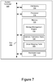
- FIG. 7 depicts a block diagram of an example system controller 120 in the storage system 110 shown in FIG. 1 , in accordance with an embodiment.
- the system controller 120 may comprise, among other components, one or more interface(s) 705 , a processor 710 , a memory 720 containing software, firmware and/or data including a storage management engine 722 , an address translation table 725 , and the stripe mapping table 600 .
- a bus 750 may be used to communicatively couple the various components of the system controller 120 .
- the system controller 120 may include alternative, additional and/or fewer components depending on the configuration, such as configurations combining elements, implementing elements in hardware vs. software, etc.
- the one or more interface(s) 705 may communicatively couple the system controller 120 to the host 101 and/or the storage array 130 .
- the one or more interface(s) 705 may include, but are not limited to, input/output (I/O) interface circuitry that uses appropriate communications protocol(s) for communicating with the host 101 and/or the storage array 130 .
- I/O input/output
- the processor 710 may be used to execute the instructions of various software programs contained in the memory 720 .
- the processor 710 may include one or more processing units and/or cores, programmable integrated circuits such as application-specific integrated circuits (ASICs) or field-programmable gate arrays (FPGAs), or some combination thereof.
- ASICs application-specific integrated circuits
- FPGAs field-programmable gate arrays
- the processor 710 may be based on various computing architectures including a complex instruction set computer (CISC) architecture, a reduced instruction set computer (RISC) architecture, or an architecture implementing a combination of instruction sets. It should be understood that other configurations of the processor 710 are possible.
- the memory 720 may store software programs, firmware and/or data that are executed or otherwise processed by the processor 710 .
- the memory 720 may comprise, for example, volatile memory such as dynamic random-access memory (DRAM) device(s), static random-access memory (SRAM) device(s), non-volatile memory such as electrically erasable programmable read-only (EEPROM) or flash memory devices, a combination of the foregoing, and/or some other suitable type of data storage medium.
- DRAM dynamic random-access memory
- SRAM static random-access memory
- EEPROM electrically erasable programmable read-only
- flash memory devices a combination of the foregoing, and/or some other suitable type of data storage medium.
- the storage management engine 722 contained in memory 720 may include routines and/or instructions that when executed by the processor 710 may perform one or more of the various storage management operations for the storage array 130 described above including operations relating to storage device rebuild and/or garbage collection.
- the address translation table 725 contained in memory 720 may include address information used by the storage management engine 722 to translate an LBA 510 to a PBA 520 in connection with the storing of data to the storage array 130 , as described above with respect to FIG. 6 .
- the stripe mapping table 600 contained in memory 720 may be used in connection with the storing or reading of data to the dynamic stripe 460 in the storage array 430 .
- one or more hardware logic module(s) 730 may be employed in place of, or as a supplement to, the software and/or firmware in the memory 720 to perform one or more of the aforementioned functions provided by the storage management engine 722 , address translation table 725 and/or stripe mapping table 600 .
- a process can generally be considered a self-consistent sequence of operations leading to a result.
- the operations may involve physical manipulations of physical quantities. These quantities take the form of electrical or magnetic signals capable of being stored, transferred, combined, compared, and otherwise manipulated. These signals may be referred to as being in the form of bits, values, elements, symbols, characters, terms, numbers or the like.
- the disclosed technologies may also relate to an apparatus for performing the operations herein.
- This apparatus may be specially constructed for the required purposes, or it may include a general-purpose computer selectively activated or reconfigured by a computer program stored in the computer.
- a computer program may be stored in a computer readable storage medium, for example, but is not limited to, any type of disk including floppy disks, optical disks, CD ROMs, and magnetic disks, read-only memories (ROMs), random access memories (RAMs), erasable programmable read-only memories (EPROMs), electrically erasable programmable read-only memories (EEPROMs), magnetic or optical cards, flash memories including USB keys with non-volatile memory or any type of media suitable for storing electronic instructions, each coupled to a computer system bus.
- the disclosed technologies can take the form of an entirely hardware implementation, an entirely software implementation or an implementation containing both hardware and software elements.
- the technology is implemented in software, which includes but is not limited to firmware, resident software, microcode, etc.
- a computer-usable or computer-readable medium can be any apparatus that can contain, store, communicate, propagate, or transport the program for use by or in connection with the instruction execution system, apparatus, or device.
- a computing system or data processing system suitable for storing and/or executing program code will include at least one processor (e.g., a hardware processor) coupled directly or indirectly to memory elements through a system bus.
- the memory elements can include local memory employed during actual execution of the program code, bulk storage, and cache memories which provide temporary storage of at least some program code in order to reduce the number of times code must be retrieved from bulk storage during execution.
- I/O devices including but not limited to keyboards, displays, pointing devices, etc.
- I/O controllers can be coupled to the system either directly or through intervening I/O controllers.
- Network adapters may also be coupled to the system to enable the data processing system to become coupled to other data processing systems or remote printers or storage devices through intervening private or public networks.
- Modems, cable modems and Ethernet cards are just a few of the currently available types of network adapters.
- storage media storage device, and data blocks are used interchangeably throughout the present disclosure to refer to the physical media upon which the data is stored.
- modules, routines, features, attributes, methodologies and other aspects of the present technology can be implemented as software, hardware, firmware or any combination of the three.
- a component an example of which is a module
- the component can be implemented as a standalone program, as part of a larger program, as a plurality of separate programs, as a statically or dynamically linked library, as a kernel loadable module, as a device driver, and/or in every and any other way known now or in the future in computer programming.
- the present techniques and technologies are in no way limited to implementation in any specific programming language, or for any specific operating system or environment. Accordingly, the disclosure of the present techniques and technologies is intended to be illustrative, but not limiting.
Landscapes
- Engineering & Computer Science (AREA)
- Theoretical Computer Science (AREA)
- Physics & Mathematics (AREA)
- General Engineering & Computer Science (AREA)
- General Physics & Mathematics (AREA)
- Quality & Reliability (AREA)
- Human Computer Interaction (AREA)
- Hardware Redundancy (AREA)
Abstract
Description
Claims (20)
Priority Applications (1)
| Application Number | Priority Date | Filing Date | Title |
|---|---|---|---|
| US15/963,829 US10860446B2 (en) | 2018-04-26 | 2018-04-26 | Failed storage device rebuild using dynamically selected locations in overprovisioned space |
Applications Claiming Priority (1)
| Application Number | Priority Date | Filing Date | Title |
|---|---|---|---|
| US15/963,829 US10860446B2 (en) | 2018-04-26 | 2018-04-26 | Failed storage device rebuild using dynamically selected locations in overprovisioned space |
Publications (2)
| Publication Number | Publication Date |
|---|---|
| US20190332504A1 US20190332504A1 (en) | 2019-10-31 |
| US10860446B2 true US10860446B2 (en) | 2020-12-08 |
Family
ID=68292609
Family Applications (1)
| Application Number | Title | Priority Date | Filing Date |
|---|---|---|---|
| US15/963,829 Active 2038-11-08 US10860446B2 (en) | 2018-04-26 | 2018-04-26 | Failed storage device rebuild using dynamically selected locations in overprovisioned space |
Country Status (1)
| Country | Link |
|---|---|
| US (1) | US10860446B2 (en) |
Cited By (2)
| Publication number | Priority date | Publication date | Assignee | Title |
|---|---|---|---|---|
| US11614893B2 (en) | 2010-09-15 | 2023-03-28 | Pure Storage, Inc. | Optimizing storage device access based on latency |
| US12008266B2 (en) | 2010-09-15 | 2024-06-11 | Pure Storage, Inc. | Efficient read by reconstruction |
Families Citing this family (4)
| Publication number | Priority date | Publication date | Assignee | Title |
|---|---|---|---|---|
| US20250104767A1 (en) * | 2018-07-11 | 2025-03-27 | Pure Storage, Inc. | Flash system including modular storage devices having reduced failure domains |
| CN110737393B (en) | 2018-07-20 | 2023-08-11 | 伊姆西Ip控股有限责任公司 | Data reading method, apparatus and computer program product |
| US11347404B2 (en) * | 2019-08-01 | 2022-05-31 | EMC IP Holding Company, LLC | System and method for sharing spare storage capacity between a log structured file system and RAID |
| US12321236B2 (en) * | 2020-05-11 | 2025-06-03 | Samsung Electronics Co., Ltd. | Systems, methods, and devices for fault resilient storage |
Citations (45)
| Publication number | Priority date | Publication date | Assignee | Title |
|---|---|---|---|---|
| US5388083A (en) * | 1993-03-26 | 1995-02-07 | Cirrus Logic, Inc. | Flash memory mass storage architecture |
| US6092215A (en) | 1997-09-29 | 2000-07-18 | International Business Machines Corporation | System and method for reconstructing data in a storage array system |
| US20030135514A1 (en) * | 2001-08-03 | 2003-07-17 | Patel Sujal M. | Systems and methods for providing a distributed file system incorporating a virtual hot spare |
| US20050080991A1 (en) * | 2003-10-09 | 2005-04-14 | International Business Machines Corporation | Method and apparatus for providing hardware aware logical volum mirrors |
| US20050114726A1 (en) | 2003-11-12 | 2005-05-26 | Ouchi Norman K. | Data recovery from multiple failed data blocks and storage units |
| US20060143503A1 (en) * | 2004-12-13 | 2006-06-29 | Dell Products L.P. | System and method of enhancing storage array read performance using a spare storage array |
| US20070245082A1 (en) | 2006-04-04 | 2007-10-18 | Margolus Norman H | Storage Assignment Technique for Scalable and Fault Tolerant Storage System |
| US7293133B1 (en) * | 2003-12-31 | 2007-11-06 | Veritas Operating Corporation | Performing operations without requiring split mirrors in a multi-class file system |
| US20080104445A1 (en) | 2006-10-31 | 2008-05-01 | Hewlett-Packard Development Company, L.P. | Raid array |
| US7596570B1 (en) * | 2003-11-04 | 2009-09-29 | Emigh Aaron T | Data sharing |
| US20100030960A1 (en) * | 2008-07-31 | 2010-02-04 | Hariharan Kamalavannan | Raid across virtual drives |
| US7783600B1 (en) | 2006-02-27 | 2010-08-24 | Symantec Operating Corporation | Redundancy management service for peer-to-peer networks |
| US20100251073A1 (en) | 2004-03-12 | 2010-09-30 | Stolowitz Michael C | Disk controller methods and apparatus with improved striping, redundancy operations and interfaces |
| US20100280998A1 (en) * | 2009-04-30 | 2010-11-04 | Microsoft Corporation | Metadata for data storage array |
| US20110029711A1 (en) | 2009-07-30 | 2011-02-03 | Cleversafe, Inc. | Method and apparatus for slice partial rebuilding in a dispersed storage network |
| US20110055178A1 (en) * | 2009-08-27 | 2011-03-03 | Cleversafe, Inc. | Dispersed storage unit and methods with metadata separation for use in a dispersed storage system |
| US20120011200A1 (en) | 2010-07-06 | 2012-01-12 | Roxbeam Media Network Corporation | Method and apparatus for data storage in a peer-to-peer network |
| US20120079317A1 (en) | 2010-09-27 | 2012-03-29 | Chandrashekar Nelogal | System and method for information handling system redundant storage rebuild |
| US8289641B1 (en) | 2008-04-18 | 2012-10-16 | Network Appliance, Inc. | Partial data storage device failures and improved storage resiliency |
| US20130179753A1 (en) | 2006-12-06 | 2013-07-11 | Fusion-Io, Inc. | Systems and methods for adaptive data storage |
| US20130268824A1 (en) | 2009-07-12 | 2013-10-10 | Apple Inc. | Adaptive over-provisioning in memory systems |
| US20130339599A1 (en) * | 2012-06-14 | 2013-12-19 | Lsi Corporation | Methods and systems for adaptive queue depth management |
| US20140237298A1 (en) | 2013-02-21 | 2014-08-21 | Sandisk Technologies Inc. | Methods, systems, and computer readable media for early detection of potential flash failures using an adaptive system level algorithm based on flash program verify |
| US20140258598A1 (en) | 2010-06-18 | 2014-09-11 | Lsi Corporation | Scalable storage devices |
| US8904261B2 (en) | 2009-12-17 | 2014-12-02 | International Business Machines Corporation | Data management in solid state storage devices |
| US20150089130A1 (en) * | 2013-09-25 | 2015-03-26 | Lenovo (Singapore) Pte. Ltd. | Dynamically allocating temporary replacement storage for a drive in a raid array |
| US20150205668A1 (en) | 2014-01-17 | 2015-07-23 | Netapp, Inc. | File system driven raid rebuild technique |
| WO2015116197A1 (en) | 2014-01-31 | 2015-08-06 | Hewlett-Packard Development Company, L.P. | Storing data based on a write allocation policy |
| US20150324262A1 (en) | 2014-05-06 | 2015-11-12 | International Business Machines Corporation | Using spare capacity in solid state drives |
| US9262278B2 (en) * | 2012-07-30 | 2016-02-16 | Ebay Inc. | Allocation of replica-sets in a storage cluster |
| US20160092309A1 (en) | 2014-09-30 | 2016-03-31 | International Business Machines Corporation | Optimization of rebuilding in solid state drives |
| US20160188424A1 (en) | 2014-12-30 | 2016-06-30 | International Business Machines Corporation | Data storage system employing a hot spare to store and service accesses to data having lower associated wear |
| US20160217040A1 (en) | 2013-08-27 | 2016-07-28 | Agency For Science, Technology And Research | Raid parity stripe reconstruction |
| US20160239397A1 (en) | 2015-02-12 | 2016-08-18 | Netapp, Inc. | Faster reconstruction of segments using a dedicated spare memory unit |
| US20160342476A1 (en) * | 2014-03-20 | 2016-11-24 | Hewlett Packard Enterprise Development Lp | Solid state drive operations |
| US20170116074A1 (en) | 2014-06-04 | 2017-04-27 | Pure Storage, Inc. | Rebuilding data across storage nodes |
| US20170123915A1 (en) * | 2015-10-29 | 2017-05-04 | Nimble Storage, Inc. | Methods and systems for repurposing system-level over provisioned space into a temporary hot spare |
| US20170269862A1 (en) * | 2016-03-15 | 2017-09-21 | International Business Machines Corporation | Storage capacity allocation using distributed spare space |
| US20170270018A1 (en) | 2016-03-21 | 2017-09-21 | EMC IP Holding Company LLC | Method and apparatus for rebuilding redundant array of independent disks |
| US20170286237A1 (en) | 2016-03-30 | 2017-10-05 | Lenovo Enterprise Solutions (Singapore) Pte. Ltd. | Peer-to-peer redundant array of independent disks (raid) lacking a raid controller |
| US20170329542A1 (en) * | 2016-05-13 | 2017-11-16 | Silicon Motion, Inc. | Method for managing data blocks and method of data management for data storage device |
| US20180032446A1 (en) | 2014-09-17 | 2018-02-01 | Commvault Systems, Inc. | Data storage systems and methods |
| US10241722B1 (en) | 2016-05-27 | 2019-03-26 | Pavilion Data Systems, Inc. | Proactive scheduling of background operations for solid state drives |
| US10289507B1 (en) | 2015-10-27 | 2019-05-14 | Pavilion Data Systems, Inc. | Distributed rebuild of failed storage device |
| US10409769B1 (en) | 2014-09-29 | 2019-09-10 | EMC IP Holding Company LLC | Data archiving in data storage system environments |
-
2018
- 2018-04-26 US US15/963,829 patent/US10860446B2/en active Active
Patent Citations (46)
| Publication number | Priority date | Publication date | Assignee | Title |
|---|---|---|---|---|
| US5388083A (en) * | 1993-03-26 | 1995-02-07 | Cirrus Logic, Inc. | Flash memory mass storage architecture |
| US6092215A (en) | 1997-09-29 | 2000-07-18 | International Business Machines Corporation | System and method for reconstructing data in a storage array system |
| US20030135514A1 (en) * | 2001-08-03 | 2003-07-17 | Patel Sujal M. | Systems and methods for providing a distributed file system incorporating a virtual hot spare |
| US20050080991A1 (en) * | 2003-10-09 | 2005-04-14 | International Business Machines Corporation | Method and apparatus for providing hardware aware logical volum mirrors |
| US7596570B1 (en) * | 2003-11-04 | 2009-09-29 | Emigh Aaron T | Data sharing |
| US20050114726A1 (en) | 2003-11-12 | 2005-05-26 | Ouchi Norman K. | Data recovery from multiple failed data blocks and storage units |
| US7293133B1 (en) * | 2003-12-31 | 2007-11-06 | Veritas Operating Corporation | Performing operations without requiring split mirrors in a multi-class file system |
| US20100251073A1 (en) | 2004-03-12 | 2010-09-30 | Stolowitz Michael C | Disk controller methods and apparatus with improved striping, redundancy operations and interfaces |
| US20060143503A1 (en) * | 2004-12-13 | 2006-06-29 | Dell Products L.P. | System and method of enhancing storage array read performance using a spare storage array |
| US7783600B1 (en) | 2006-02-27 | 2010-08-24 | Symantec Operating Corporation | Redundancy management service for peer-to-peer networks |
| US20070245082A1 (en) | 2006-04-04 | 2007-10-18 | Margolus Norman H | Storage Assignment Technique for Scalable and Fault Tolerant Storage System |
| US20080104445A1 (en) | 2006-10-31 | 2008-05-01 | Hewlett-Packard Development Company, L.P. | Raid array |
| US20130179753A1 (en) | 2006-12-06 | 2013-07-11 | Fusion-Io, Inc. | Systems and methods for adaptive data storage |
| US8289641B1 (en) | 2008-04-18 | 2012-10-16 | Network Appliance, Inc. | Partial data storage device failures and improved storage resiliency |
| US20100030960A1 (en) * | 2008-07-31 | 2010-02-04 | Hariharan Kamalavannan | Raid across virtual drives |
| US20100280998A1 (en) * | 2009-04-30 | 2010-11-04 | Microsoft Corporation | Metadata for data storage array |
| US20130268824A1 (en) | 2009-07-12 | 2013-10-10 | Apple Inc. | Adaptive over-provisioning in memory systems |
| US20110029711A1 (en) | 2009-07-30 | 2011-02-03 | Cleversafe, Inc. | Method and apparatus for slice partial rebuilding in a dispersed storage network |
| US20110055178A1 (en) * | 2009-08-27 | 2011-03-03 | Cleversafe, Inc. | Dispersed storage unit and methods with metadata separation for use in a dispersed storage system |
| US8904261B2 (en) | 2009-12-17 | 2014-12-02 | International Business Machines Corporation | Data management in solid state storage devices |
| US20140258598A1 (en) | 2010-06-18 | 2014-09-11 | Lsi Corporation | Scalable storage devices |
| US20120011200A1 (en) | 2010-07-06 | 2012-01-12 | Roxbeam Media Network Corporation | Method and apparatus for data storage in a peer-to-peer network |
| US20120079317A1 (en) | 2010-09-27 | 2012-03-29 | Chandrashekar Nelogal | System and method for information handling system redundant storage rebuild |
| US20130339599A1 (en) * | 2012-06-14 | 2013-12-19 | Lsi Corporation | Methods and systems for adaptive queue depth management |
| US9262278B2 (en) * | 2012-07-30 | 2016-02-16 | Ebay Inc. | Allocation of replica-sets in a storage cluster |
| US20140237298A1 (en) | 2013-02-21 | 2014-08-21 | Sandisk Technologies Inc. | Methods, systems, and computer readable media for early detection of potential flash failures using an adaptive system level algorithm based on flash program verify |
| US20160217040A1 (en) | 2013-08-27 | 2016-07-28 | Agency For Science, Technology And Research | Raid parity stripe reconstruction |
| US20150089130A1 (en) * | 2013-09-25 | 2015-03-26 | Lenovo (Singapore) Pte. Ltd. | Dynamically allocating temporary replacement storage for a drive in a raid array |
| US20150205669A1 (en) | 2014-01-17 | 2015-07-23 | Netapp, Inc. | File system driven raid rebuild technique |
| US20150205668A1 (en) | 2014-01-17 | 2015-07-23 | Netapp, Inc. | File system driven raid rebuild technique |
| WO2015116197A1 (en) | 2014-01-31 | 2015-08-06 | Hewlett-Packard Development Company, L.P. | Storing data based on a write allocation policy |
| US20160342476A1 (en) * | 2014-03-20 | 2016-11-24 | Hewlett Packard Enterprise Development Lp | Solid state drive operations |
| US20150324262A1 (en) | 2014-05-06 | 2015-11-12 | International Business Machines Corporation | Using spare capacity in solid state drives |
| US20170116074A1 (en) | 2014-06-04 | 2017-04-27 | Pure Storage, Inc. | Rebuilding data across storage nodes |
| US20180032446A1 (en) | 2014-09-17 | 2018-02-01 | Commvault Systems, Inc. | Data storage systems and methods |
| US10409769B1 (en) | 2014-09-29 | 2019-09-10 | EMC IP Holding Company LLC | Data archiving in data storage system environments |
| US20160092309A1 (en) | 2014-09-30 | 2016-03-31 | International Business Machines Corporation | Optimization of rebuilding in solid state drives |
| US20160188424A1 (en) | 2014-12-30 | 2016-06-30 | International Business Machines Corporation | Data storage system employing a hot spare to store and service accesses to data having lower associated wear |
| US20160239397A1 (en) | 2015-02-12 | 2016-08-18 | Netapp, Inc. | Faster reconstruction of segments using a dedicated spare memory unit |
| US10289507B1 (en) | 2015-10-27 | 2019-05-14 | Pavilion Data Systems, Inc. | Distributed rebuild of failed storage device |
| US20170123915A1 (en) * | 2015-10-29 | 2017-05-04 | Nimble Storage, Inc. | Methods and systems for repurposing system-level over provisioned space into a temporary hot spare |
| US20170269862A1 (en) * | 2016-03-15 | 2017-09-21 | International Business Machines Corporation | Storage capacity allocation using distributed spare space |
| US20170270018A1 (en) | 2016-03-21 | 2017-09-21 | EMC IP Holding Company LLC | Method and apparatus for rebuilding redundant array of independent disks |
| US20170286237A1 (en) | 2016-03-30 | 2017-10-05 | Lenovo Enterprise Solutions (Singapore) Pte. Ltd. | Peer-to-peer redundant array of independent disks (raid) lacking a raid controller |
| US20170329542A1 (en) * | 2016-05-13 | 2017-11-16 | Silicon Motion, Inc. | Method for managing data blocks and method of data management for data storage device |
| US10241722B1 (en) | 2016-05-27 | 2019-03-26 | Pavilion Data Systems, Inc. | Proactive scheduling of background operations for solid state drives |
Non-Patent Citations (6)
| Title |
|---|
| International Search Report and Written Opinion of Application No. PCT/US2018/062498, Filed Nov. 26, 2018 (20 pages). |
| International Search Report and Written Opinion of Internationals Application No. PCT/US2019/035087, dated Sep. 25, 2019, 11 pages. |
| International Search Report and Written Opinion of Internationals Application No. PCT/US2019/035088, dated Sep. 26, 2019, 10 pages. |
| U.S. Appl. No. 15/722,665, entitled "Redundancy Coding Stripe Based on Coordinated Internal Address Scheme Across Multiple Devices," filed Oct. 20, 2017 (73 pages). |
| U.S. Appl. No. 15/722,666, entitled "Redundancy Coding Stripe Based on Coordinated Internal Address Scheme Across Multiple Devices," filed Oct. 20, 2017 (73 pages). |
| U.S. Appl. No. 15/936,327, entitled "Data Storage Drive Rebuild with Parity Generation Offload Using Peer-to-Peer Data Transfers," filed Mar. 26, 2018 (85 pages). |
Cited By (3)
| Publication number | Priority date | Publication date | Assignee | Title |
|---|---|---|---|---|
| US11614893B2 (en) | 2010-09-15 | 2023-03-28 | Pure Storage, Inc. | Optimizing storage device access based on latency |
| US12008266B2 (en) | 2010-09-15 | 2024-06-11 | Pure Storage, Inc. | Efficient read by reconstruction |
| US12282686B2 (en) | 2010-09-15 | 2025-04-22 | Pure Storage, Inc. | Performing low latency operations using a distinct set of resources |
Also Published As
| Publication number | Publication date |
|---|---|
| US20190332504A1 (en) | 2019-10-31 |
Similar Documents
| Publication | Publication Date | Title |
|---|---|---|
| US11210170B2 (en) | Failed storage device rebuild method | |
| US10831603B2 (en) | Rebuild assist using failed storage device | |
| US10860446B2 (en) | Failed storage device rebuild using dynamically selected locations in overprovisioned space | |
| US11941257B2 (en) | Method and apparatus for flexible RAID in SSD | |
| CN107870730B (en) | Method and system for managing storage system | |
| US10067844B2 (en) | Method of channel content rebuild in ultra-high capacity SSD | |
| CN104461391A (en) | Method and system for managing and processing metadata of storage equipment | |
| JP2019502987A (en) | Multipage failure recovery in non-volatile memory systems | |
| US10229000B2 (en) | Erasure codes to prevent lower page corruption in flash memory | |
| JP2016530637A (en) | RAID parity stripe reconstruction | |
| CN102799533B (en) | Method and apparatus for shielding damaged sector of disk | |
| CN110737395B (en) | I/O management method, electronic device, and computer-readable storage medium | |
| US10509697B2 (en) | Data storage device and operating method therefor | |
| CN107885620B (en) | Method and system for improving performance and reliability of solid-state disk array | |
| US20180357142A1 (en) | Reporting defects in a flash memory back-up system | |
| CN104615381B (en) | A kind of redundant arrays of inexpensive disks of video monitoring system | |
| US11461020B2 (en) | Memory device equipped with data protection scheme | |
| US11093339B2 (en) | Storage utilizing a distributed cache chain and a checkpoint drive in response to a data drive corruption | |
| CN119960673A (en) | A redundant array management method and system based on ZNS solid state drive | |
| US20220254435A1 (en) | Semiconductor storage device and error processing method for defective memory cell in the device | |
| US12079084B2 (en) | Distributed raid for parity-based flash storage devices |
Legal Events
| Date | Code | Title | Description |
|---|---|---|---|
| FEPP | Fee payment procedure |
Free format text: ENTITY STATUS SET TO UNDISCOUNTED (ORIGINAL EVENT CODE: BIG.); ENTITY STATUS OF PATENT OWNER: LARGE ENTITY |
|
| AS | Assignment |
Owner name: WESTERN DIGITAL TECHNOLOGIES, INC., CALIFORNIA Free format text: ASSIGNMENT OF ASSIGNORS INTEREST;ASSIGNORS:BOLKHOVITIN, VLADISLAV;MUNNANGI, SIVA;SIGNING DATES FROM 20180423 TO 20180425;REEL/FRAME:045747/0339 |
|
| STPP | Information on status: patent application and granting procedure in general |
Free format text: NON FINAL ACTION MAILED |
|
| AS | Assignment |
Owner name: JPMORGAN CHASE BANK, N.A., AS AGENT, ILLINOIS Free format text: SECURITY INTEREST;ASSIGNOR:WESTERN DIGITAL TECHNOLOGIES, INC.;REEL/FRAME:052915/0566 Effective date: 20200113 |
|
| STPP | Information on status: patent application and granting procedure in general |
Free format text: RESPONSE TO NON-FINAL OFFICE ACTION ENTERED AND FORWARDED TO EXAMINER |
|
| STPP | Information on status: patent application and granting procedure in general |
Free format text: ADVISORY ACTION MAILED |
|
| STPP | Information on status: patent application and granting procedure in general |
Free format text: DOCKETED NEW CASE - READY FOR EXAMINATION |
|
| STPP | Information on status: patent application and granting procedure in general |
Free format text: PUBLICATIONS -- ISSUE FEE PAYMENT VERIFIED |
|
| STCF | Information on status: patent grant |
Free format text: PATENTED CASE |
|
| AS | Assignment |
Owner name: WESTERN DIGITAL TECHNOLOGIES, INC., CALIFORNIA Free format text: RELEASE OF SECURITY INTEREST AT REEL 052915 FRAME 0566;ASSIGNOR:JPMORGAN CHASE BANK, N.A.;REEL/FRAME:059127/0001 Effective date: 20220203 |
|
| AS | Assignment |
Owner name: JPMORGAN CHASE BANK, N.A., ILLINOIS Free format text: PATENT COLLATERAL AGREEMENT - A&R LOAN AGREEMENT;ASSIGNOR:WESTERN DIGITAL TECHNOLOGIES, INC.;REEL/FRAME:064715/0001 Effective date: 20230818 Owner name: JPMORGAN CHASE BANK, N.A., ILLINOIS Free format text: PATENT COLLATERAL AGREEMENT - DDTL LOAN AGREEMENT;ASSIGNOR:WESTERN DIGITAL TECHNOLOGIES, INC.;REEL/FRAME:067045/0156 Effective date: 20230818 |
|
| FEPP | Fee payment procedure |
Free format text: MAINTENANCE FEE REMINDER MAILED (ORIGINAL EVENT CODE: REM.); ENTITY STATUS OF PATENT OWNER: LARGE ENTITY |
|
| FEPP | Fee payment procedure |
Free format text: SURCHARGE FOR LATE PAYMENT, LARGE ENTITY (ORIGINAL EVENT CODE: M1554); ENTITY STATUS OF PATENT OWNER: LARGE ENTITY |
|
| MAFP | Maintenance fee payment |
Free format text: PAYMENT OF MAINTENANCE FEE, 4TH YEAR, LARGE ENTITY (ORIGINAL EVENT CODE: M1551); ENTITY STATUS OF PATENT OWNER: LARGE ENTITY Year of fee payment: 4 |