US10860109B2 - Tactile presentation device - Google Patents
Tactile presentation device Download PDFInfo
- Publication number
- US10860109B2 US10860109B2 US16/549,095 US201916549095A US10860109B2 US 10860109 B2 US10860109 B2 US 10860109B2 US 201916549095 A US201916549095 A US 201916549095A US 10860109 B2 US10860109 B2 US 10860109B2
- Authority
- US
- United States
- Prior art keywords
- vibration
- plate
- terminal plate
- presentation device
- terminal
- Prior art date
- Legal status (The legal status is an assumption and is not a legal conclusion. Google has not performed a legal analysis and makes no representation as to the accuracy of the status listed.)
- Expired - Fee Related
Links
Images


Classifications
-
- G—PHYSICS
- G06—COMPUTING OR CALCULATING; COUNTING
- G06F—ELECTRIC DIGITAL DATA PROCESSING
- G06F3/00—Input arrangements for transferring data to be processed into a form capable of being handled by the computer; Output arrangements for transferring data from processing unit to output unit, e.g. interface arrangements
- G06F3/01—Input arrangements or combined input and output arrangements for interaction between user and computer
- G06F3/016—Input arrangements with force or tactile feedback as computer generated output to the user
-
- B—PERFORMING OPERATIONS; TRANSPORTING
- B06—GENERATING OR TRANSMITTING MECHANICAL VIBRATIONS IN GENERAL
- B06B—METHODS OR APPARATUS FOR GENERATING OR TRANSMITTING MECHANICAL VIBRATIONS OF INFRASONIC, SONIC, OR ULTRASONIC FREQUENCY, e.g. FOR PERFORMING MECHANICAL WORK IN GENERAL
- B06B1/00—Methods or apparatus for generating mechanical vibrations of infrasonic, sonic, or ultrasonic frequency
- B06B1/02—Methods or apparatus for generating mechanical vibrations of infrasonic, sonic, or ultrasonic frequency making use of electrical energy
- B06B1/06—Methods or apparatus for generating mechanical vibrations of infrasonic, sonic, or ultrasonic frequency making use of electrical energy operating with piezoelectric effect or with electrostriction
- B06B1/0607—Methods or apparatus for generating mechanical vibrations of infrasonic, sonic, or ultrasonic frequency making use of electrical energy operating with piezoelectric effect or with electrostriction using multiple elements
- B06B1/0622—Methods or apparatus for generating mechanical vibrations of infrasonic, sonic, or ultrasonic frequency making use of electrical energy operating with piezoelectric effect or with electrostriction using multiple elements on one surface
-
- G—PHYSICS
- G01—MEASURING; TESTING
- G01H—MEASUREMENT OF MECHANICAL VIBRATIONS OR ULTRASONIC, SONIC OR INFRASONIC WAVES
- G01H11/00—Measuring mechanical vibrations or ultrasonic, sonic or infrasonic waves by detecting changes in electric or magnetic properties
- G01H11/06—Measuring mechanical vibrations or ultrasonic, sonic or infrasonic waves by detecting changes in electric or magnetic properties by electric means
-
- G—PHYSICS
- G06—COMPUTING OR CALCULATING; COUNTING
- G06F—ELECTRIC DIGITAL DATA PROCESSING
- G06F3/00—Input arrangements for transferring data to be processed into a form capable of being handled by the computer; Output arrangements for transferring data from processing unit to output unit, e.g. interface arrangements
- G06F3/01—Input arrangements or combined input and output arrangements for interaction between user and computer
- G06F3/03—Arrangements for converting the position or the displacement of a member into a coded form
- G06F3/041—Digitisers, e.g. for touch screens or touch pads, characterised by the transducing means
-
- B—PERFORMING OPERATIONS; TRANSPORTING
- B06—GENERATING OR TRANSMITTING MECHANICAL VIBRATIONS IN GENERAL
- B06B—METHODS OR APPARATUS FOR GENERATING OR TRANSMITTING MECHANICAL VIBRATIONS OF INFRASONIC, SONIC, OR ULTRASONIC FREQUENCY, e.g. FOR PERFORMING MECHANICAL WORK IN GENERAL
- B06B1/00—Methods or apparatus for generating mechanical vibrations of infrasonic, sonic, or ultrasonic frequency
- B06B1/02—Methods or apparatus for generating mechanical vibrations of infrasonic, sonic, or ultrasonic frequency making use of electrical energy
- B06B1/06—Methods or apparatus for generating mechanical vibrations of infrasonic, sonic, or ultrasonic frequency making use of electrical energy operating with piezoelectric effect or with electrostriction
Definitions
- a certain aspect of the embodiments is related to a tactile presentation device that presents a tactile feeling by adding vibration of an ultrasonic band, for example.
- Patent Document 1 International Publication Pamphlet No. 2015/045059. It is known that a piezoelectric vibration plate and a terminal body are bonded with a flexible resin bonding material (see Patent Document 2: Japanese Laid-open Patent Publication No. 2008-091971). There is known a piezoelectric transformer supporting tool that includes grooves for leading lead wires provided at positions corresponding to vibration nodes (see Patent Document 3: Japanese Laid-open Patent Publication No. 08-236831, for example).
- a tactile presentation device includes: a substrate including a vibration plate and a terminal plate which are integrally formed; an actuator that is provided on the vibration plate, and generates a standing wave of ultrasonic vibration; a terminal that is provided on an end of the terminal plate, and electrically connects the actuator to an external; a fixing member that fixes the vibration plate to a support; and a vibration suppressor that is provided between the terminal and the fixing member, and suppresses the ultrasonic vibration transmitted from the vibration plate to the support.
- FIG. 1 is a perspective view of a tactile presentation device according to a first embodiment
- FIG. 2A is a cross-section diagram taken on a line A-A of FIG. 1 ;
- FIG. 2B is a cross-section diagram taken on a line B-B of FIG. 1 ;
- FIG. 3 is a plane view of a substrate according to the first embodiment
- FIG. 4 is a block diagram of the tactile presentation device according to the first embodiment
- FIGS. 5A to 5C are cross-section diagrams of the tactile presentation device according to a second embodiment, and a first variation and a second variation thereof;
- FIG. 6 is a perspective view of the tactile presentation device according to a third variation of the second embodiment.
- FIGS. 7A and 7B are cross-section diagrams of the tactile presentation device according to a third embodiment and a first variation thereof;
- FIGS. 8A to 8F are cross-section diagrams of a terminal plate of the tactile presentation device according to a fourth embodiment
- FIG. 9 is a perspective view illustrating a cross-section surface of the terminal plate according to the fourth embodiment.
- FIGS. 10A to 10F are plane views of the terminal plate of the tactile presentation device according to a fifth embodiment
- FIGS. 11A to 11C are plane views of the terminal plate of the tactile presentation device according to the fifth embodiment.
- FIG. 12 is a plane view illustrating a vibration plate
- FIG. 13 is a diagram illustrating the vibration of a standing wave by using a displacement with respect to a position X;
- FIGS. 14A and 14B are plane views of the substrate according to a sixth embodiment.
- FIGS. 15A and 15B are plane views of the substrate according to a first variation of the sixth embodiment.
- FIG. 1 is a perspective view of a tactile presentation device according to a first embodiment.
- FIG. 2A is a cross-section diagram taken on a line A-A of FIG. 1
- FIG. 2B is a cross-section diagram taken on a line B-B of FIG. 1 .
- a plane direction of a substrate 10 is represented as an X-direction and a Y-direction, and a normal direction of the substrate 10 is represented as a Z-direction, as illustrated in FIGS. 1, 2A and 2B .
- a recess 17 is provided in a housing 16 as a support, and a touch panel 14 is housed in the recess 17 .
- the substrate 10 is disposed on the touch panel 14 .
- the substrate 10 includes a vibration plate 20 and a terminal plate 22 which are formed integrally. Fixing members 12 extending in the X-direction are provided at both ends of a back surface of the vibration plate 20 of the substrate 10 in the Y-direction. The substrate 10 is fixed to the housing 16 by the fixing members 12 . Terminals 21 are provided on an end of the terminal plate 22 . The terminals 21 are inserted into a connector 18 , so that they are electrically connected to the housing 16 . Piezoelectric elements 24 as actuators are provided at both ends of the back surface of the vibration plate 20 in the X-direction.
- FIG. 3 is a plane view of the substrate according to the first embodiment.
- the piezoelectric elements 24 provided at both ends of the vibration plate 20 are extended in the Y-direction, as illustrated in FIG. 3 .
- Electrodes 26 are provided at both ends of each piezoelectric element 24 in the Y-direction.
- the electrodes 26 are electrically connected to the terminals 21 via wirings 28 provided on the back surface of the substrate 10 .
- the terminals 21 are electrically connected to the housing 16 via the connector 18 .
- an alternating current (AC) signal is applied to the pair of electrodes 26 through the wirings 28 , each piezoelectric element 24 vibrates, and a standing wave of an ultrasonic band is generated in the X-direction of a vibration region 25 .
- AC alternating current
- the surface of the vibration plate 20 vibrates in an ultrasonic band of 25 to 40 kHz for example, and a part of a human body, e.g. a finger is trying to touch the surface of the vibration plate 20 , a high pressure air layer occurs between the finger and the vibration plate 20 . For this reason, a friction between the finger and the vibration plate 20 is reduced. This effect is called a squeeze effect. Thereby, a user feels a slippery feeling with the finger. When the generation and non-generation of the vibration is periodically repeated in the vibration region 25 , the user feels a rough or irregularity feeling. Thus, by applying the ultrasonic vibration to the vibration plate 20 , it is possible to present a tactile feeling to the user.
- the terminal plate 22 leads the wirings 28 from the vibration plate 20 to the terminals 21 .
- the width of the terminal plate 22 in the X direction is required such that the wirings 28 can be provided on the terminal plate 22 .
- the width of the vibration plate 20 in the X direction is, for example, several tens to several hundreds mm, and the width of the terminal plate 22 in the X direction is, for example, 10 mm.
- Each fixing member 12 is made of a hard material such as a metal like brass or stainless steel, or a glass, for example.
- the housing 16 is made of a material that can maintain a certain shape at the time of use, such as a resin like ABS (Acrylonitrile Butadiene Styrene), or a metal.
- the fixing member 12 and the housing 16 are rigid bodies.
- the piezoelectric element 24 vibrates by the AC signal.
- the electrode 26 electrically connects the wiring 28 and the piezoelectric element 24 to each other, and is made of a metal layer such as a copper layer, a silver layer or a gold layer, for example.
- the wiring 28 is made of the metal layer such as the copper layer, the silver layer or the gold layer, and is a silver paste, for example.
- the piezoelectric element 24 , the electrode 26 and the wiring 28 may be provided on a front surface of the substrate 10 .
- the terminal 21 is made of plated metal layers such as gold layers or nickel layers provided on both surfaces of the substrate 10 .
- the terminal 21 may be thicker than the wiring 28 .
- FIG. 4 is a block diagram of the tactile presentation device according to the first embodiment.
- the touch panel 14 is provided under the substrate 10 as illustrated in FIG. 4 .
- the touch panel 14 can detect the position of a finger 56 touched on the substrate 10 .
- a position detection circuit 50 detects the coordinates of the touch panel 14 which the finger 56 touches.
- a control circuit 52 controls on and off of the AC signal to be applied to the piezoelectric element 24 depending on a detection result of the position detection circuit 50 .
- a drive circuit 54 applies or does not apply the AC signal to the piezoelectric element 24 via the connector 18 , the terminal 21 and the wiring 28 depending on the control of the control circuit 52 . Thereby, the user feels the tactile feeling with the finger.
- the position detection circuit 50 , the control circuit 52 and the drive circuit 54 may be provided in the touch panel 14 or may be housed in the housing 16 .
- the respective circuits 50 , 52 and 54 may be provided in an information terminal on which the touch panel 14 is mounted.
- Each of the substrate 10 and the touch panel 14 has a permeability in which a visible light is transmitted, and a display may be provided under the touch panel 14 .
- the vibration plate 20 and the connector 18 are connected with a member which hardly transfers the vibration such as a flexible printed circuit board (FPC).
- FPC flexible printed circuit board
- the vibration plate 20 and the terminal plate 22 are formed integrally, there are advantages that the cost of the substrate 10 can be reduced, a contact point with the vibration plate 20 can be formed by only the connector 18 , the manufacturing process does not increase, and the possibility of disconnection is low.
- the vibration plate 20 and the terminal plate 22 which are integrally formed constitute the substrate 10 made of a single rigid body.
- the vibration plate 20 and the terminal plate 22 share a layer made of the same material.
- the vibration plate 20 and the terminal plate 22 are located in the same plane.
- the substrate 10 includes the vibration plate 20 and the terminal plate 22 which are integrally formed, as illustrated in FIG. 3 .
- the piezoelectric elements 24 are provided on the vibration plate 20 , and generate the standing wave of the ultrasonic band on the surface of the vibration plate 20 which the human body can touch.
- the terminals 21 are provided on the end of the terminal plate 22 , and electrically connect the piezoelectric elements 24 to an external device or a processor.
- One of the fixing members 12 near the terminal plate 22 fixes the substrate 10 to the housing 16 between the vibration plate 20 and the terminals 21 .
- a vibration suppressor 30 for suppressing the ultrasonic vibration transmitted from the vibration plate 20 to the terminals 21 is provided between the terminals 21 and the fixing member 12 . Thereby, it is possible to suppress the vibration transmitted from the vibration plate 20 to the terminals 21 .
- FIGS. 5A to 5C are cross-section diagrams of the tactile presentation device according to a second embodiment, and a first variation and a second variation thereof.
- an absorbing member 32 is provided on the fixing member 12 near the terminal plate 22 so as to sandwich the substrate 10 .
- the fixing member 12 near the terminal plate 22 is referred to as “a first fixing member 12 a ”
- the fixing member 12 away from the terminal plate 22 is referred to as “a second fixing member 12 b ”.
- the absorbing member 32 is provided on the terminal plate 22 having a width in the X-direction smaller than a width of the vibration plate 20 .
- the absorbing member 32 is fixed to the first fixing member 12 a .
- the other configurations of the tactile presentation device in the second embodiment are the same as those of the tactile presentation device in the first embodiment, and therefore description thereof is omitted.
- the absorbing member 32 is provided between the substrate 10 and the first fixing member 12 a , and a part of the absorbing member 32 is not provided on an upper surface of the substrate 10 .
- the other configurations of the tactile presentation device in the first variation are the same as those of the tactile presentation device in the second embodiment, and therefore description thereof is omitted.
- the absorbing member 32 is provided away from the terminals 21 and the first fixing member 12 a .
- the absorbing member 32 is provided between the substrate 10 and the housing 16 , and is fixed to the housing 16 .
- the part of the absorbing member 32 is not provided on an upper surface of the substrate 10 .
- the other configurations of the tactile presentation device in the second variation are the same as those of the tactile presentation device in the first variation of the second embodiment, and therefore description thereof is omitted.
- the absorbing member 32 may be provided so as to sandwich the substrate 10 .
- FIG. 6 is a perspective view of the tactile presentation device according to a third variation of the second embodiment.
- the absorbing member 32 is in contact with the first fixing member 12 a , and is provided on the housing 16 .
- the absorbing member 32 is provided so as to sandwich the substrate 10 .
- the other configurations of the tactile presentation device in the third variation are the same as those of the tactile presentation device in the second embodiment, and therefore description thereof is omitted.
- the absorbing member 32 absorbs the ultrasonic vibration.
- a material that easily absorbs the ultrasonic vibration includes polyethylene terephthalate (PET), liquid crystal polymer (LCP), acrylic resin (e.g. PMMA: polymethyl methacrylate), polybutylene terephthalate (PBT), polycarbonate (PC), cycloolefin polymer (COP), polyethylene (PE) or polypropylene (PP), for example.
- the absorbing member 32 for absorbing the vibration of the standing wave generated in the vibration plate 20 serves as the vibration suppressor 30 . Thereby, it is possible to suppress the ultrasonic vibration transmitted from the vibration plate 20 to the terminals 21 .
- the absorbing member 32 may be provided so as to mechanically connect the first fixing member 12 a and the substrate 10 . Moreover, as described in the second and the third variations of the second embodiment, the absorbing member 32 may be provided so as to mechanically connect the substrate 10 and the housing 16 between the first fixing member 12 a and the terminals 21 .
- FIGS. 7A and 7B are cross-section diagrams of the tactile presentation device according to a third embodiment and a first variation thereof.
- a weight 34 is provided between the first fixing member 12 a and the terminals 21 of the terminal plate 22 illustrated in FIG. 7A .
- the weight 34 is not in contact with the housing 16 , and a gap is formed between the weight 34 and the housing 16 .
- the weight 34 is made of material having higher density than the substrate 10 for example, and is a metal such as iron or copper.
- the weight 34 may be provided on at least one of the front surface and the back surface of the terminal plate 22 .
- the other configurations of the tactile presentation device in the third embodiment are the same as those of the tactile presentation device in the first embodiment, and therefore description thereof is omitted.
- the terminal plate 22 includes a thickness part thicker than the vibration plate 20 , and the thickness part serves as a weight 34 a .
- the other configurations of the tactile presentation device in the first variation of the third embodiment are the same as those of the tactile presentation device in the third embodiment, and therefore description thereof is omitted.
- the vibration plate 20 vibrates between the two fixing members 12 fixed to the housing 16 , and the terminal plate 22 vibrates between the first fixing member 12 a and the connector 18 which are fixed to the housing 16 .
- the vibration of the vibration plate 20 is propagated to the terminal plate 22 , and the terminal plate 22 also vibrates. Therefore, the weight 34 is provided on the terminal plate 22 in order to shift the resonance frequency of the terminal plate 22 from the resonance frequency of the vibration plate 20 .
- the resonance frequency of the terminal plate 22 differs from that of the vibration plate 20 , and the weight 34 is disposed near the connector 18 away from the first fixing member 12 a .
- the terminal plate 22 is hardly to vibrate even when the vibration plate 20 vibrates.
- the weight 34 provided on the terminal plate 22 serves as the vibration suppressor 30 to suppress the vibration of the terminal plate 22 . Further, since the terminal plate 22 is heavy by the weight 34 , it is possible to expect an effect that the terminal plate 22 is hardly to vibrate by the weight.
- the part of the substrate 10 that is thicker than the vibration plate 20 can serve as the weight 34 .
- FIGS. 8A to 8F are cross-section diagrams of the terminal plate 22 of the tactile presentation device according to a fourth embodiment.
- Each of the terminal plates 22 illustrated in FIGS. 8A to 8F has a thin part 36 thinner than the vibration plate 20 as at least a part of the terminal plate 22 .
- the thin part 36 is provided on a part of the terminal plate 22 which has the same thickness as the vibration plate 20 and is located between the terminals 21 and the first fixing member 12 a .
- the thin part 36 is formed on the terminal plate 22 near the first fixing member 12 a .
- a part of the terminal plate 22 sandwiched between the terminals 21 has the same thickness as the vibration plate 20 .
- the part of the terminal plate 22 sandwiched between the terminals 21 has a thickness thinner than the vibration plate 20 .
- the thin part 36 of the terminal plate 22 is thinned stepwise toward the terminals 21 from the fixing member 12 a .
- the thickness of the terminal plate 22 near the first fixing member 12 a is the same as that of the vibration plate 20 , and the thin part 36 is provided on the terminal plate 22 near the terminals 21 .
- the shape of the thin part 36 of the terminal plate 22 is a waveform.
- FIG. 8F almost all region of the terminal plate 22 is the thin part 36 , and the thickness of the terminal plate 22 is substantially constant.
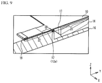
- FIG. 9 is a perspective view illustrating a cross-section surface of the terminal plate 22 according to the fourth embodiment.
- the thin part 36 is provided on the terminal plate 22 near the first fixing member 12 a .
- the thin part 36 is provided on the front surface of the substrate 10 .
- the thin part 36 is not provided on the terminal plate 22 near the terminals 21 , and the terminal plate 22 has substantially the same thickness as the vibration plate 20 .
- the ultrasonic vibration is absorbed and suppressed by the thin part 36 .
- the thickness of the thin part 36 is 3 ⁇ 4 or less and 1 ⁇ 4 or more of the thickness of the vibration plate 20 , for example.
- the thin part 36 needs to be provided on at least one of the front surface and the back surface of the terminal plate 22 .
- the vibration suppressor 30 constitutes a part of the substrate 10 , and the thin part 36 thinner than the vibration plate 20 serves as the vibration suppressor 30 . Thereby, it is possible to suppress the transmission of the ultrasonic vibration from the vibration plate 20 to the terminals 21 . Since the terminal plate 22 is flexible, the work of inserting the terminals 21 into the connector 18 is facilitated.
- the part of the terminal plate 22 sandwiched between the terminals 21 is thicker than the thin part 36 .
- FIGS. 8C to 8F the part of the terminal plate 22 sandwiched between the terminals 21 is thinner than the vibration plate 20 . Thereby, it is possible to more suppress the transmission of the vibration from the vibration plate 20 to the terminals 21 .
- FIGS. 10A to 11C are plane views of the terminal plate 22 of the tactile presentation device according to a fifth embodiment.
- a narrow part 38 constituting a part of the substrate 10 is provided on the terminal plate 22 near the first fixing member 12 a .
- the narrow part 38 is formed at the root of the terminal plate 22 extending from the vibration plate 20 .
- the width of the narrow part 38 in the X-direction is smaller than the width of a part of terminal plate 22 where the terminals 21 are provided. Since the rigidity of the narrow part 38 is reduced, the narrow part 38 suppresses the transmission of the ultrasonic vibration and serves as the vibration suppressor.
- a wide part 39 having a width in the X-direction wider than the part of the terminal plate 22 where the terminals 21 are provided is provided on the terminal plate 22 near the first fixing member 12 a .
- the width of the wide part 39 is continuously reduced toward the ⁇ Y-direction. Thereby, the terminal plate 22 becomes flexible as approaching the terminals 21 , and can suppress the vibration.
- FIGS. 10C to 10F the width of the terminal plate 22 in the X-direction is substantially constant as illustrated in FIGS. 10C to 10F , at least one opening 40 is provided on the terminal plate 22 .
- a single opening 40 is provided between two central wirings 28 among four wirings 28 .
- the opening 40 is provided in the center of the terminal plate 22 .
- FIG. 10D a plurality of openings 40 are provided between four respective wirings 28 .
- the openings 40 are provided on the terminal plate 22 in a matrix shape.
- FIG. 10E a single slit-like opening 40 is provided between four respective wirings 28 .
- ladder-like openings 40 are provided between two central wirings 28 among the four wirings 28 .
- the terminal plate 22 including at least one opening 40 serves as the vibration suppressor 30 . Since the rigidity of the part of the terminal plate 22 where the at least one opening 40 is provided is reduced, the transmission of the ultrasonic vibration is suppressed by this part of the terminal plate 22 .
- the openings 40 and the narrow parts 38 are provided on the terminal plate 22 , and a part of the terminal plate 22 has a truss shape.
- the openings 40 and the narrow parts 38 are provided on the terminal plate 22 , and a part of the terminal plate 22 has a plurality of spring shapes.
- the terminal plate 22 has a meandering shape.
- the thin part 36 may be narrow like the narrow part 38 .
- FIG. 12 is a plane view illustrating the vibration plate 20 .
- nodes 60 and antinodes 62 of the standing wave alternately appear between the piezoelectric elements 24 in the X-direction.
- An interval between the adjacent nodes 60 is 1 ⁇ 2 of a wavelength of the standing wave, and an interval between the node 60 and the antinode 62 adjacent to each other is 1 ⁇ 4 of a wavelength of the standing wave.
- FIG. 13 is a diagram illustrating the vibration of the standing wave by using a displacement with respect to each position on the vibration plate 20 in the X-direction.
- Marks “A” to in FIG. 13 denote time variation of the displacement.
- a vertical axis denotes an amplitude, and a horizontal axis denotes a position X.
- Each alternate long and short dash line denotes the node 60
- each dotted line denotes the antinode 62 .
- the node 60 and the antinode 62 are alternately generated.
- the vibration changes in the order of A, B, C, D, E, D, C, B and A. As can be seen from FIG.
- the displacement at the node 60 is 0 regardless of time, and this position does not vibrate.
- a displacement amount at the antinode 62 is the greatest. Adjacent antinodes 62 are displaced in a reverse phase.
- FIGS. 14A and 14B are plane views of the substrate 10 according to a sixth embodiment.
- one or more rod members 42 which are a part of the substrate 10 are connected between the terminal plate 22 and the vibration plate 20 .
- the rod members 42 are connected to portions of the vibration plate 20 corresponding to the nodes 60 .
- the rod members 42 are not connected to portions of the vibration plate 20 corresponding to the antinodes 62 , and the openings 40 are provided on the portions of the vibration plate 20 corresponding to the antinodes 62 .
- the wirings 28 (not illustrated) are connected between the vibration plate 20 and the terminal plate 22 through any of the rod members 42 .
- the other configurations of the tactile presentation device are the same as those of the tactile presentation device in the first embodiment, and therefore description thereof is omitted.
- the rod members 42 may be provided at an interval between adjacent nodes 60 as illustrated in FIG. 14A , or may be provided on the portions of the vibration plate 20 corresponding to the nodes 60 skipping the adjacent node 60 as illustrated in FIG. 14B .
- the interval between the nodes 60 is 5-6 mm.
- the width of the rod member 42 in the X-direction is set to 1.5 mm or less, for example. It is preferable that the width of the rod member 42 is 1 ⁇ 8 or less of the wavelength of the standing wave.
- the plurality of rod members 42 are preferably provided.
- the rod members 42 which connects the terminal plate 22 to the portions of the vibration plate 20 corresponding to the nodes 60 and are not connected to the portions of the vibration plate 20 corresponding to the antinodes 62 serve as the vibration suppressor 30 .
- the vibration suppressor 30 As illustrated in FIG. 13 , the displacement of the vibration plate 20 at the nodes 60 is small. Therefore, the rod members 42 are connected to the portions of the vibration plate 20 corresponding to the nodes 60 and not connected to the portions of the vibration plate 20 corresponding to the antinodes 62 , so that the transmission of the vibration is suppressed.
- the terminal plate 22 is connected to the portions of the vibration plate 20 corresponding to the nodes 60 via the rod members 42 . Thereby, it is possible to increase a junction strength between the vibration plate 20 and the terminal plate 22 and suppress the transmission of the ultrasonic vibration from the vibration plate 20 to the terminal plate 22 .
- FIGS. 15A and 15B are plane views of the substrate 10 according to a first variation of the sixth embodiment.
- a plurality of rod members 42 a and a plurality of rod members 42 b are connected between the terminal plate 22 and the vibration plate 20 , as illustrated in FIGS. 15A and 15B .
- a pair of rod members 42 a and 42 b are connected to portions of the vibration plate 20 corresponding to the adjacent antinodes 62 , and connected to the same portion of the terminal plate 22 .
- the wirings 28 (not illustrated) are connected between the vibration plate 20 and the terminal plate 22 through any of the rod members 42 a to 42 c .
- the other configurations of the tactile presentation device are the same as those of the tactile presentation device in the sixth embodiment, and therefore description thereof is omitted.
- a planar shape of the pair of rod members 42 a and 42 b is a V-shape.
- the rod members 42 a and 42 b may be connected to the rod member 42 c
- the rod member 42 c may be connected to the terminal plate 22 .
- the planar shape of the rod members 42 a , 42 b and 42 c is a Y-shape.
- the rod members 42 a and 42 b which connect the terminal plate 22 to the portions of the vibration plate 20 corresponding to the antinodes 62 of the reverse phase of the standing wave serve as the vibration suppressor 30 .
- the rod members 42 a and 42 b are connected to each other near the terminal plate 22 .
- the displacements of the vibration plate 20 in the adjacent antinodes 62 are the reverse phase, as illustrated in FIG. 13 .
- the rod members 42 a and 42 b are connected to the portions of the vibration plate 20 corresponding to the adjacent antinodes 62
- the rod members 42 a and 42 b are connected to each other near the terminal plate 22 .
- the vibrations of the reverse phase overlap with each other to be canceled, and therefore the vibration of the terminal plate 22 is suppressed.
- the vibrations applied to the rod members 42 a and 42 b having one end connected to each other may be the reverse phase.
- the adjacent antinodes 62 are not the reverse phase, there is a case where the antinodes 62 of the reverse phase are present.
- the portions of the vibration plate 20 to which the rod members 42 a and 42 b are connected may not necessarily be disposed at positions corresponding to the adjacent antinodes 62 .
- the rod members 42 a and 42 b can be connected to positions other than the portions of the vibration plate 20 corresponding to the antinodes 62 .
- the wavelength of the standing wave is determined by conditions such as the shape of the vibration plate 20 , and a driving frequency for driving the piezoelectric elements 24 .
- the positions of the nodes 60 and the antinodes 62 of the standing wave to be generated on the vibration plate 20 also are determined. Therefore, it is possible to determine the portions of the vibration plate 20 to be connected to the rod members 42 a and 42 b.
- the planar shape of the pair of rod members 42 a and 42 b is the V-shape as illustrated in FIG. 15A or the Y-shape as illustrated in FIG. 15B . Thereby, it is possible to ensure the mechanical strength of the rod members 42 a to 42 c and cancel the vibrations of the reverse phase of the rod members 42 a and 42 b.
- each of the widths of the rod members 42 a and 42 b is 1 ⁇ 8 or less of the wavelength of the standing wave.
- the plurality pairs of rod members 42 a and 42 b are preferably provided.
- the first to the sixth embodiments and its variations may be appropriately combined with each other.
Landscapes
- Engineering & Computer Science (AREA)
- General Engineering & Computer Science (AREA)
- Theoretical Computer Science (AREA)
- Physics & Mathematics (AREA)
- General Physics & Mathematics (AREA)
- Human Computer Interaction (AREA)
- Mechanical Engineering (AREA)
- User Interface Of Digital Computer (AREA)
- Apparatuses For Generation Of Mechanical Vibrations (AREA)
Abstract
Description
Claims (8)
Applications Claiming Priority (2)
| Application Number | Priority Date | Filing Date | Title |
|---|---|---|---|
| JP2018-170297 | 2018-09-12 | ||
| JP2018170297A JP2020042609A (en) | 2018-09-12 | 2018-09-12 | Feel presentation device |
Publications (2)
| Publication Number | Publication Date |
|---|---|
| US20200081542A1 US20200081542A1 (en) | 2020-03-12 |
| US10860109B2 true US10860109B2 (en) | 2020-12-08 |
Family
ID=69719158
Family Applications (1)
| Application Number | Title | Priority Date | Filing Date |
|---|---|---|---|
| US16/549,095 Expired - Fee Related US10860109B2 (en) | 2018-09-12 | 2019-08-23 | Tactile presentation device |
Country Status (2)
| Country | Link |
|---|---|
| US (1) | US10860109B2 (en) |
| JP (1) | JP2020042609A (en) |
Families Citing this family (2)
| Publication number | Priority date | Publication date | Assignee | Title |
|---|---|---|---|---|
| WO2022043813A1 (en) * | 2020-08-27 | 2022-03-03 | 3M Innovative Properties Company | Haptic articles and applications using sintered articles prepared from molded gel compositions |
| JP7796517B2 (en) | 2021-11-29 | 2026-01-09 | 上海天馬微電子有限公司 | tactile presentation device |
Citations (13)
| Publication number | Priority date | Publication date | Assignee | Title |
|---|---|---|---|---|
| JPH08236831A (en) | 1995-02-28 | 1996-09-13 | Tokin Corp | Piezoelectric transformer support |
| JP2008091971A (en) | 2006-09-29 | 2008-04-17 | Daishinku Corp | Piezoelectric vibration device |
| US20110241851A1 (en) * | 2010-03-31 | 2011-10-06 | New Scale Technologies | Haptic actuator systems and methods thereof |
| US20110262126A1 (en) * | 2010-04-26 | 2011-10-27 | Olympus Corporation | Vibrating device and image equipment having the same |
| US20120162500A1 (en) * | 2010-12-22 | 2012-06-28 | Olympus Imaging Corp. | Vibrating device and image equipment having the same |
| US20120313874A1 (en) * | 2011-06-07 | 2012-12-13 | Stmicroelectronics (Grenoble 2) Sas | Method of manufacturing a vibratory actuator for a touch panel with haptic feedback |
| US20140327839A1 (en) * | 2011-05-09 | 2014-11-06 | Universite Lille 1-Sciences Et Technologies | Transparent Vibrating Touch Interface |
| US20140347322A1 (en) * | 2013-09-26 | 2014-11-27 | Fujitsu Limited | Drive controlling apparatus, electronic device and drive controlling method |
| US20160313796A1 (en) * | 2015-04-27 | 2016-10-27 | Samsung Electronics Co., Ltd. | Apparatus and method of forming localized vibration field, and method of disposing exciters |
| US20170090575A1 (en) * | 2015-09-30 | 2017-03-30 | Fujitsu Limited | Tactile-sensation transmitting device, terminal device, and tactile-sensation transmitting method |
| US20180039331A1 (en) * | 2016-08-03 | 2018-02-08 | Apple Inc. | Haptic Output System for User Input Surface |
| US20180329499A1 (en) * | 2016-01-07 | 2018-11-15 | Fujitsu Limited | Electronic device and drive control method thereof |
| US20180348873A1 (en) * | 2017-05-31 | 2018-12-06 | Denso Ten Limited | Input device |
-
2018
- 2018-09-12 JP JP2018170297A patent/JP2020042609A/en active Pending
-
2019
- 2019-08-23 US US16/549,095 patent/US10860109B2/en not_active Expired - Fee Related
Patent Citations (15)
| Publication number | Priority date | Publication date | Assignee | Title |
|---|---|---|---|---|
| JPH08236831A (en) | 1995-02-28 | 1996-09-13 | Tokin Corp | Piezoelectric transformer support |
| JP2008091971A (en) | 2006-09-29 | 2008-04-17 | Daishinku Corp | Piezoelectric vibration device |
| US20110241851A1 (en) * | 2010-03-31 | 2011-10-06 | New Scale Technologies | Haptic actuator systems and methods thereof |
| US20110262126A1 (en) * | 2010-04-26 | 2011-10-27 | Olympus Corporation | Vibrating device and image equipment having the same |
| US20120162500A1 (en) * | 2010-12-22 | 2012-06-28 | Olympus Imaging Corp. | Vibrating device and image equipment having the same |
| US20140327839A1 (en) * | 2011-05-09 | 2014-11-06 | Universite Lille 1-Sciences Et Technologies | Transparent Vibrating Touch Interface |
| US20120313874A1 (en) * | 2011-06-07 | 2012-12-13 | Stmicroelectronics (Grenoble 2) Sas | Method of manufacturing a vibratory actuator for a touch panel with haptic feedback |
| US20140347322A1 (en) * | 2013-09-26 | 2014-11-27 | Fujitsu Limited | Drive controlling apparatus, electronic device and drive controlling method |
| WO2015045059A1 (en) | 2013-09-26 | 2015-04-02 | 富士通株式会社 | Drive control apparatus, electronic device, and drive control method |
| US20160313796A1 (en) * | 2015-04-27 | 2016-10-27 | Samsung Electronics Co., Ltd. | Apparatus and method of forming localized vibration field, and method of disposing exciters |
| US20170090575A1 (en) * | 2015-09-30 | 2017-03-30 | Fujitsu Limited | Tactile-sensation transmitting device, terminal device, and tactile-sensation transmitting method |
| JP2017068709A (en) | 2015-09-30 | 2017-04-06 | 富士通株式会社 | Tactile transmission device, terminal apparatus and tactile transmission method |
| US20180329499A1 (en) * | 2016-01-07 | 2018-11-15 | Fujitsu Limited | Electronic device and drive control method thereof |
| US20180039331A1 (en) * | 2016-08-03 | 2018-02-08 | Apple Inc. | Haptic Output System for User Input Surface |
| US20180348873A1 (en) * | 2017-05-31 | 2018-12-06 | Denso Ten Limited | Input device |
Non-Patent Citations (3)
| Title |
|---|
| Fujitsu Limited, Fujitsu Laboratories Ltd., "Fujitsu Develops Prototype Haptic Sensory Tablet", Press Release, Feb. 24, 2014, https://pr.fujitsu.com/jp/news/2014/02/24.html, 6 pp. |
| Patenscope English abstract for International Patent Publication No. WO 2015/045059 A1, published Apr. 2, 2015. |
| Toshio Watanabe et al., "Control of Tactile Surface-Roughness Sensation Using Ultrasonic Vibration", Transactions of the Japan Society of Mechanical Engineers, Series C, vol. 62, Issue 596, Apr. 25, 1996, pp. 1329-1334. |
Also Published As
| Publication number | Publication date |
|---|---|
| JP2020042609A (en) | 2020-03-19 |
| US20200081542A1 (en) | 2020-03-12 |
Similar Documents
| Publication | Publication Date | Title |
|---|---|---|
| CN103529990B (en) | Piezoelectric element and electronic device | |
| US10126819B2 (en) | Vibration generating device and manipulation feeling imparting input device using the vibration generating device | |
| US10496173B2 (en) | Manipulation feeling imparting input device | |
| TW200405153A (en) | Wiring structure of touch panel | |
| JP7110570B2 (en) | vibration unit | |
| KR101109226B1 (en) | Piezoelectric actuator module and touch screen device using same | |
| US10860109B2 (en) | Tactile presentation device | |
| US8941599B2 (en) | Touch panel-attached display device and antistatic structure | |
| US11307710B2 (en) | Position detecting device including antenna function and display device | |
| KR20110023032A (en) | Touch screen device | |
| JP2016226175A (en) | Piezoelectric body, vibrator, and vibration wave motor | |
| KR101095128B1 (en) | Touch screen device | |
| CN120380446A (en) | Sensor and position detection device | |
| KR101109357B1 (en) | Actuator module | |
| US10468956B2 (en) | Electrical component with moving mass and flexible cables | |
| JP2002027592A (en) | Piezoelectric speaker | |
| JP4222160B2 (en) | Input device and manufacturing method thereof | |
| JP2017050709A (en) | Electrostatic loudspeaker | |
| US11323046B2 (en) | Vibration unit having a piezoelectric element as the vibration source | |
| JP2012043362A (en) | Display device with input function | |
| JP7679344B2 (en) | Vibration device and device including same | |
| JP7737825B2 (en) | Vibration generating device and electronic device | |
| JP2019212265A (en) | Vibration unit, driving device, and method for driving | |
| JP2011030290A (en) | Piezoelectric actuator and touch panel device using the same | |
| KR20120130994A (en) | Piezo Actuator |
Legal Events
| Date | Code | Title | Description |
|---|---|---|---|
| FEPP | Fee payment procedure |
Free format text: ENTITY STATUS SET TO UNDISCOUNTED (ORIGINAL EVENT CODE: BIG.); ENTITY STATUS OF PATENT OWNER: LARGE ENTITY |
|
| AS | Assignment |
Owner name: FUJITSU COMPONENT LIMITED, JAPAN Free format text: ASSIGNMENT OF ASSIGNORS INTEREST;ASSIGNORS:AKABANE, AYUMU;SHIMIZU, NAOKI;TAKEI, FUMIO;REEL/FRAME:050219/0059 Effective date: 20190808 |
|
| STPP | Information on status: patent application and granting procedure in general |
Free format text: EX PARTE QUAYLE ACTION MAILED |
|
| STPP | Information on status: patent application and granting procedure in general |
Free format text: RESPONSE TO EX PARTE QUAYLE ACTION ENTERED AND FORWARDED TO EXAMINER |
|
| STPP | Information on status: patent application and granting procedure in general |
Free format text: NOTICE OF ALLOWANCE MAILED -- APPLICATION RECEIVED IN OFFICE OF PUBLICATIONS |
|
| STPP | Information on status: patent application and granting procedure in general |
Free format text: PUBLICATIONS -- ISSUE FEE PAYMENT VERIFIED |
|
| STCF | Information on status: patent grant |
Free format text: PATENTED CASE |
|
| FEPP | Fee payment procedure |
Free format text: MAINTENANCE FEE REMINDER MAILED (ORIGINAL EVENT CODE: REM.); ENTITY STATUS OF PATENT OWNER: LARGE ENTITY |
|
| LAPS | Lapse for failure to pay maintenance fees |
Free format text: PATENT EXPIRED FOR FAILURE TO PAY MAINTENANCE FEES (ORIGINAL EVENT CODE: EXP.); ENTITY STATUS OF PATENT OWNER: LARGE ENTITY |
|
| STCH | Information on status: patent discontinuation |
Free format text: PATENT EXPIRED DUE TO NONPAYMENT OF MAINTENANCE FEES UNDER 37 CFR 1.362 |
|
| FP | Lapsed due to failure to pay maintenance fee |
Effective date: 20241208 |