US10859533B2 - Parameter estimation method and parameter estimation device - Google Patents
Parameter estimation method and parameter estimation device Download PDFInfo
- Publication number
- US10859533B2 US10859533B2 US16/126,112 US201816126112A US10859533B2 US 10859533 B2 US10859533 B2 US 10859533B2 US 201816126112 A US201816126112 A US 201816126112A US 10859533 B2 US10859533 B2 US 10859533B2
- Authority
- US
- United States
- Prior art keywords
- package
- data
- parameter
- vibration
- packages
- Prior art date
- Legal status (The legal status is an assumption and is not a legal conclusion. Google has not performed a legal analysis and makes no representation as to the accuracy of the status listed.)
- Active, expires
Links
- 238000000034 method Methods 0.000 title claims abstract description 31
- 230000005484 gravity Effects 0.000 claims description 38
- 238000012856 packing Methods 0.000 claims description 35
- 238000012546 transfer Methods 0.000 claims description 35
- 238000006073 displacement reaction Methods 0.000 claims description 31
- 239000000463 material Substances 0.000 claims description 22
- 239000000853 adhesive Substances 0.000 claims description 21
- 230000001070 adhesive effect Effects 0.000 claims description 21
- 238000003384 imaging method Methods 0.000 claims description 16
- 238000005314 correlation function Methods 0.000 claims description 15
- 230000001133 acceleration Effects 0.000 claims description 12
- 230000003287 optical effect Effects 0.000 claims description 9
- 230000009466 transformation Effects 0.000 claims description 5
- 230000004044 response Effects 0.000 claims description 3
- 230000006870 function Effects 0.000 description 34
- 238000005259 measurement Methods 0.000 description 15
- 238000001514 detection method Methods 0.000 description 6
- 238000007689 inspection Methods 0.000 description 4
- 230000005855 radiation Effects 0.000 description 4
- XAGFODPZIPBFFR-UHFFFAOYSA-N aluminium Chemical compound [Al] XAGFODPZIPBFFR-UHFFFAOYSA-N 0.000 description 3
- 230000008859 change Effects 0.000 description 3
- 229910052782 aluminium Inorganic materials 0.000 description 2
- 238000006243 chemical reaction Methods 0.000 description 2
- 229920003023 plastic Polymers 0.000 description 2
- 230000001902 propagating effect Effects 0.000 description 2
- 238000001228 spectrum Methods 0.000 description 2
- 239000002390 adhesive tape Substances 0.000 description 1
- 238000005452 bending Methods 0.000 description 1
- 230000008901 benefit Effects 0.000 description 1
- 230000005540 biological transmission Effects 0.000 description 1
- 230000000254 damaging effect Effects 0.000 description 1
- 230000007423 decrease Effects 0.000 description 1
- 238000013461 design Methods 0.000 description 1
- 239000000428 dust Substances 0.000 description 1
- 230000000694 effects Effects 0.000 description 1
- 238000009434 installation Methods 0.000 description 1
- 238000012986 modification Methods 0.000 description 1
- 230000004048 modification Effects 0.000 description 1
- 230000010363 phase shift Effects 0.000 description 1
- 230000008569 process Effects 0.000 description 1
- 238000005316 response function Methods 0.000 description 1
- 238000006467 substitution reaction Methods 0.000 description 1
- 125000000391 vinyl group Chemical group [H]C([*])=C([H])[H] 0.000 description 1
- 229920002554 vinyl polymer Polymers 0.000 description 1
- 230000000007 visual effect Effects 0.000 description 1
- XLYOFNOQVPJJNP-UHFFFAOYSA-N water Substances O XLYOFNOQVPJJNP-UHFFFAOYSA-N 0.000 description 1
Images


Classifications
-
- G—PHYSICS
- G01—MEASURING; TESTING
- G01G—WEIGHING
- G01G3/00—Weighing apparatus characterised by the use of elastically-deformable members, e.g. spring balances
- G01G3/12—Weighing apparatus characterised by the use of elastically-deformable members, e.g. spring balances wherein the weighing element is in the form of a solid body stressed by pressure or tension during weighing
- G01G3/16—Weighing apparatus characterised by the use of elastically-deformable members, e.g. spring balances wherein the weighing element is in the form of a solid body stressed by pressure or tension during weighing measuring variations of frequency of oscillations of the body
-
- G—PHYSICS
- G01—MEASURING; TESTING
- G01G—WEIGHING
- G01G9/00—Methods of, or apparatus for, the determination of weight, not provided for in groups G01G1/00 - G01G7/00
-
- G—PHYSICS
- G01—MEASURING; TESTING
- G01M—TESTING STATIC OR DYNAMIC BALANCE OF MACHINES OR STRUCTURES; TESTING OF STRUCTURES OR APPARATUS, NOT OTHERWISE PROVIDED FOR
- G01M1/00—Testing static or dynamic balance of machines or structures
- G01M1/12—Static balancing; Determining position of centre of gravity
- G01M1/122—Determining position of centre of gravity
-
- G—PHYSICS
- G01—MEASURING; TESTING
- G01N—INVESTIGATING OR ANALYSING MATERIALS BY DETERMINING THEIR CHEMICAL OR PHYSICAL PROPERTIES
- G01N29/00—Investigating or analysing materials by the use of ultrasonic, sonic or infrasonic waves; Visualisation of the interior of objects by transmitting ultrasonic or sonic waves through the object
- G01N29/04—Analysing solids
- G01N29/043—Analysing solids in the interior, e.g. by shear waves
-
- G—PHYSICS
- G01—MEASURING; TESTING
- G01N—INVESTIGATING OR ANALYSING MATERIALS BY DETERMINING THEIR CHEMICAL OR PHYSICAL PROPERTIES
- G01N29/00—Investigating or analysing materials by the use of ultrasonic, sonic or infrasonic waves; Visualisation of the interior of objects by transmitting ultrasonic or sonic waves through the object
- G01N29/04—Analysing solids
- G01N29/045—Analysing solids by imparting shocks to the workpiece and detecting the vibrations or the acoustic waves caused by the shocks
-
- G—PHYSICS
- G01—MEASURING; TESTING
- G01N—INVESTIGATING OR ANALYSING MATERIALS BY DETERMINING THEIR CHEMICAL OR PHYSICAL PROPERTIES
- G01N29/00—Investigating or analysing materials by the use of ultrasonic, sonic or infrasonic waves; Visualisation of the interior of objects by transmitting ultrasonic or sonic waves through the object
- G01N29/04—Analysing solids
- G01N29/12—Analysing solids by measuring frequency or resonance of acoustic waves
-
- G—PHYSICS
- G01—MEASURING; TESTING
- G01N—INVESTIGATING OR ANALYSING MATERIALS BY DETERMINING THEIR CHEMICAL OR PHYSICAL PROPERTIES
- G01N29/00—Investigating or analysing materials by the use of ultrasonic, sonic or infrasonic waves; Visualisation of the interior of objects by transmitting ultrasonic or sonic waves through the object
- G01N29/22—Details, e.g. general constructional or apparatus details
- G01N29/225—Supports, positioning or alignment in moving situation
-
- G—PHYSICS
- G01—MEASURING; TESTING
- G01N—INVESTIGATING OR ANALYSING MATERIALS BY DETERMINING THEIR CHEMICAL OR PHYSICAL PROPERTIES
- G01N29/00—Investigating or analysing materials by the use of ultrasonic, sonic or infrasonic waves; Visualisation of the interior of objects by transmitting ultrasonic or sonic waves through the object
- G01N29/22—Details, e.g. general constructional or apparatus details
- G01N29/26—Arrangements for orientation or scanning by relative movement of the head and the sensor
- G01N29/262—Arrangements for orientation or scanning by relative movement of the head and the sensor by electronic orientation or focusing, e.g. with phased arrays
-
- G—PHYSICS
- G01—MEASURING; TESTING
- G01N—INVESTIGATING OR ANALYSING MATERIALS BY DETERMINING THEIR CHEMICAL OR PHYSICAL PROPERTIES
- G01N29/00—Investigating or analysing materials by the use of ultrasonic, sonic or infrasonic waves; Visualisation of the interior of objects by transmitting ultrasonic or sonic waves through the object
- G01N29/44—Processing the detected response signal, e.g. electronic circuits specially adapted therefor
- G01N29/46—Processing the detected response signal, e.g. electronic circuits specially adapted therefor by spectral analysis, e.g. Fourier analysis or wavelet analysis
-
- G06K9/00624—
-
- G—PHYSICS
- G01—MEASURING; TESTING
- G01N—INVESTIGATING OR ANALYSING MATERIALS BY DETERMINING THEIR CHEMICAL OR PHYSICAL PROPERTIES
- G01N2291/00—Indexing codes associated with group G01N29/00
- G01N2291/02—Indexing codes associated with the analysed material
- G01N2291/028—Material parameters
- G01N2291/0289—Internal structure, e.g. defects, grain size, texture
Definitions
- Embodiments described herein relate generally to a parameter estimation method and a parameter estimation device.
- miscellaneous packages are transferred by using a robot.
- parameters such as a size, a shape and a material of a package, and a weight and a position of a gravity center of the package are also various.
- a gripping plan including a position to be gripped or the like is created in accordance with image information acquired by a camera or the like.
- the gripping is performed in accordance with the gripping plan, there is a case when the gripping fails or the package is broken due to a mistake in recognition regarding a range of an integrated package, or because the weight and the gravity center are unknown.
- a plurality of packages integrally disposed with an adhesive, a vinyl wrap, and the like are difficult to be recognized that they are not individual packages but integrated from the image information. Even if existence of the plurality of packages is recognized when it is seen from above, the packages cannot be transferred one by one when they are integrated, and the plurality of packages have to be lifted all at once. In such a case, the gripping is likely to fail if it cannot be recognized that the plurality of packages are integrated. Accordingly, it is necessary to estimate the weight or the gravity center when the gripping plan of the package is created, and to perform the gripping in consideration of the parameters.
- the weight and the gravity center of the plurality of packages which are integrated are preferably estimated through a non-contact inspection.
- An example of a non-contact device detecting the above-stated parameters includes, for example, an X-ray inspection device, or the like.
- the package has to be put into the X-ray inspection device.
- a throughput of packages per a unit time is huge at a distribution site or the like, the throughput decreases in a case when the above-described method is used.
- the X-ray inspection device is expensive, large-sized, and may have a damaging effect on human bodies.
- FIG. 1 is a schematic view illustrating a configuration example of an estimation device.
- FIG. 2 is a flowchart to explain an estimation method example.
- FIG. 3 is a view to explain a principle of an ultrasonic phased array.
- FIG. 4 is a schematic view to explain a transfer function.
- FIG. 5 is a schematic view illustrating a packing example.
- FIG. 6 is a schematic view illustrating a packing example.
- FIG. 7 is a schematic view illustrating a packing example.
- FIG. 8 is a view illustrating an outer shape of a corrugated carton.
- FIG. 9 is a view illustrating a structure of a cross-section of a cardboard which is elements of corrugated carton.
- FIG. 10 is a top of view illustrating a vibration point and a vibration mode measurement point of a corrugated carton.
- FIG. 11 is a view illustrating a transfer function.
- FIG. 12 is a view illustrating a transfer function.
- FIG. 13 is a view illustrating a relation between a natural frequency and a weight.
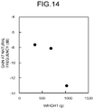
- FIG. 14 is a view illustrating a relation between a gain of a natural vibration and a weight.
- FIG. 15 is a view illustrating a configuration of a robot hand.
- FIG. 16 is a view illustrating a relation between a vibration frequency and a weight.
- FIG. 17 is a view illustrating a constitution of a package of Sample A.
- FIG. 18 is a view illustrating a constitution of a package of Sample B.
- FIG. 19 is a view illustrating a vibration mode.
- FIG. 20 is a view illustrating a vibration mode.
- FIG. 21 is an upper surface view illustrating a constitution of a plurality of packages integrally disposed.
- FIG. 22 is a flowchart to explain another example of an estimation method.
- a parameter estimation method comprises: acquiring appearance information including a shape information and a position information of at least one package of a plurality of packages each having a packing material and a content packed by using the packing material; vibrating the at least one package at least at one position selected in accordance with the appearance information, and acquiring at least one data showing a vibration of the at least one package, the at least one data being selected from the group consisting of acceleration, speed and displacement; and estimating a value of at least one parameter of the at least one package in accordance with a relation between the at least one data and the at least one parameter, the at least one parameter being selected from the group consisting of: a weight of the content; a weight of the at least one package; a gravity center of the content; a gravity center of the at least one package; a range of two or more of the contents integrally disposed; a range of two or more of the packages integrally disposed; an adhesive condition of two or more of the contents; and an adhesive condition of two or more of the at least one packages.
- FIG. 1 is a schematic view illustrating a configuration example of a parameter estimation device.
- An estimation device 1 illustrated in FIG. 1 is able to estimate a value of at least one parameter, which is selected from the group consisting of: a weight of a content; a weight of a package; a gravity center of the content; a gravity center of the package; a range of the contents integrally disposed; a range of the packages integrally disposed; an adhesive condition of two or more of the contents with each other; and an adhesive condition of two or more of the packages with each other, of a package 10 by using a driving part 1 a , and includes an imaging device 11 , an vibrator 12 , a detector 13 , a storage 14 , an estimation device 15 , and a control part 16 .
- the estimation device 1 is used to design, for example, a gripping plan of a package.
- the package 10 has a packing material 10 a and a content 10 b packed with the packing material 10 a .
- An example of the packing material 10 a includes, for example, a corrugated carton, or the like, but it is not limited thereto.
- An example of the content 10 b is not particularly limited as long as it can be packed with the packing material 10 a .
- a shape of the package 10 is not also limited to a rectangular parallelepiped shape.
- the package 10 may be one of packing matters where a plurality of packages is integrated.
- the adhesive condition of two or more of the packages with each other or the contents with each other is decided by a state of another package or content which is not gripped when one package or content is gripped to be lifted.
- a degree of adherence is stronger than a reference, or strength of adherence is higher than a reference
- another package or content is not lifted, it is decided that they do not adhere, the degree of adherence is weaker than the reference, or the strength of adherence is lower than the reference.
- a case when a plurality of corrugated cartons partially adhere with a tape, an adhesive, and the like is discriminated.
- the cartons are integrally lifted when a part thereof is gripped, it is decided that they adhere, the degree of adherence is stronger than the reference, or the strength of adherence is high.
- a plastic bag is used as the packing material, and a plurality of contents are contained therein, and if the plurality of contents are integrally lifted when a part of the plurality of contents is gripped, it is decided that the plurality of contents adhere with the tape, the adhesive, and the like, the degree of adherence is stronger than the reference, or the strength of adherence is high.
- the imaging device 11 in FIG. 1 is able to capture an image of the package 10 . Appearance information including a shape and a position of the package 10 can be thereby acquired.
- the imaging device 11 includes, for example, an imaging element such as a camera.
- the vibrator 12 is able to excite the package 10 .
- the vibrator 12 has a sonic oscillator such as, for example, an annular array having a ring-shaped vibrator which is concentrically located in order to vary a focal position, an ultrasonic array and an ultrasonic phased array each having a plurality of vibrators which are arranged side by side on a curvature.
- the ultrasonic array is able to effectively excite a target because sound pressures from a plurality pieces of vibrators are overlapped.
- the ultrasonic phased array is able to generate an acoustic radiation pressure. Breakage of the package 10 due to vibration can be suppressed by using these sonic oscillators because non-contact vibration of the package 10 is possible.
- the detector 13 is able to acquire data showing a vibration or a change due to the vibration of the package 10 .
- the detector 13 has at least one sensor selected from the group consisting of: for example, an electrostatic capacitance type non-contact displacement meter; an eddy-current type non-contact displacement meter; an optical non-contact displacement meter; an ultrasonic displacement meter; and a laser Doppler vibration meter. Breakage of the package 10 due to detection can be prevented by using a sensor capable of performing non-contact detection.
- the aforementioned plurality of sensors may be combined.
- the optical non-contact displacement meter is suitable for the detection of displacement at a relatively distant place, has high detection accuracy, and fast response speed, and so on.
- the ultrasonic displacement meter is suitable for the detection of displacement at a nearer place than the optical meter with low frequency, unlikely to be affected by a material and a color of the package 10 , and less affected by dust and water.
- the storage 14 is able to store, for example, a lookup table (LUT).
- the LUT shows a relation between, for example, the above-stated at least one parameter and the above-stated at least one data.
- the storage 14 has, for example, a memory.
- the storage 14 may store data such as the appearance information and a vibration point.
- the storage 14 does not necessarily store the LUT.
- the estimation device 15 is able to process the data and refer to the LUT stored in the storage 14 to estimate a value of the parameter corresponding to the acquired data.
- the control part 16 is electrically connected to each of the imaging device 11 , the vibrator 12 , the detector 13 , the storage 14 and the estimation device 15 , and outputs a control signal to each part.
- the control part 16 controls operations of each of the imaging device 11 , the vibrator 12 , the detector 13 , the storage 14 , and the estimation device 15 by the control signal.
- the control part 16 may control the operations by being connected to at least one of the imaging device 11 , the vibrator 12 , the detector 13 , the storage 14 , and the estimation device 15 .
- the estimation device 15 and the control part 16 each may be constituted by hardware using, for example, a processor or the like. Each operation may be executed by storing each operation to a computer-readable storage medium such as a memory as an operation program, and appropriately reading the operation program stored in the storage medium by the hardware.
- a computer-readable storage medium such as a memory as an operation program
- FIG. 2 is a flowchart to explain an example of the parameter estimation method.
- the parameter estimation method example illustrated in FIG. 2 includes an appearance information acquisition step S 1 , a data acquisition step S 2 , and a parameter estimation step S 3 .
- the appearance information acquisition step S 1 includes an imaging step S 1 - 1 where the package 10 is image-captured by the imaging device 11 , and at least one appearance information between the shape and the position of the package 10 is acquired, and an vibration point decision step S 1 - 2 where an exciting position of the package 10 is decided in accordance with the appearance information.
- the data acquisition step S 2 includes an vibration step S 2 - 1 where the package 10 is vibrated at least at decided one exciting position, and a vibration measurement step S 2 - 2 where at least one data selected from the group consisting of: acceleration; speed; and displacement of the package 10 and showing a vibration of the package 10 is acquired.
- a fast Fourier transformation (FFT) step S 2 - 4 where a fast Fourier transformation of the data is performed by the estimation device 15 and a transfer function arithmetic operation step S 2 - 5 where the data after the fast Fourier transformation is converted into a transfer function may further be included after a step S 2 - 3 where the data is analog-digital converted (analog-digital conversion: ADC) as illustrated in FIG. 2 .
- the vibration step S 2 - 1 and the vibration measurement step S 2 - 2 may be performed at each of a first surface and a second surface of the package 10 .
- the exciting position and a data acquisition position may not necessarily coincide.
- FIG. 3 is a view to explain a principle of the ultrasonic phased array.
- N-pieces of ultrasonic oscillators 121 are controlled by drive signals 122 .
- Drive phases of the N-pieces of ultrasonic oscillators 121 are controlled such that phases from all of the ultrasonic oscillators 121 are the same at a position to be vibrated, resulting in that a focused ultrasonic beam is formed at the position to be vibrated (a position 123 ).
- the acoustic radiation pressure is in proportion to the square of an amplitude of the ultrasonic wave, resulting in that the acoustic radiation pressure becomes N 2 when the number of ultrasonic oscillators 121 of the phased array is N-pieces.
- a vibration according to the vibration is vibrated at a surface of the package 10 .
- a frequency and an amplitude of the vibrated vibration differ depending on a weight of a content in the package 10 , a position of a gravity center which is defined according to the position of the content, further, a structure, a material, and so on of the package.
- the ultrasonic array oscillator there are various shapes and combinations as the ultrasonic array oscillator, and they are appropriately selected according to a shape, an installation location, and so on of the package 10 to be vibrated.
- the annular array may be used.
- a pulse of the drive signal 122 is sequentially applied from the ultrasonic oscillator 121 at an outside toward the ultrasonic oscillator 121 at a center.
- the focused ultrasonic beam is thereby formed at the position to be vibrated (the position 123 ).
- a linear array which can focus on only one dimension and the annular array where phases are converged on two dimensions are combined to synthesize acoustic energy.
- the detector 13 acquires at least one data which is acquired by exciting the package 10 , selected from the group consisting of: the acceleration; the speed; and the displacement of the package 10 , and shows the vibration of the package 10 .
- FIG. 4 is a schematic view to explain a transfer function.
- the transfer function is a function which converts an input x(t) to a system into an output y(t) as illustrated in FIG. 4 .
- An input-output system of a vibration system is represented by a convolution integral illustrated by an expression (1).
- [Mathematical expression 1] y ( t ) ⁇ ⁇ ⁇ x ( ⁇ ) h ( t ⁇ ) d ⁇ expression (1)
- the transfer function H( ⁇ ) is represented by an expression (3).
- C xy ( ⁇ ) is a cross spectrum
- P xy ( ⁇ ) is an input power spectrum.
- the transfer function composed of the gain (amplitude) and the phase is calculated by using the expression (4) from the amplitude and the frequency of a vibration mode of the vibration.
- the parameter estimation step S 3 includes a LUT reference step S 3 - 1 and an output step S 3 - 2 .
- the obtained transfer function is collated with the LUT shoving a relation between the transfer function and the weight or the gravity center of the package 10 which is acquired in advance.
- the output step S 3 - 2 values of parameters relating to the weight of the package, the gravity center, the range of two or more of the packages integrally disposed, the adhesive condition of two or more of the packages with each other or the contents with each other which are the most probable corresponding to the transfer function are output as data.
- An optimum LUT is selected according to an application target. For example, the LUT may use the output data in itself from the detector 13 , or may use the transfer function generated by converting the output data.
- the LUT may be created by previously acquiring the data by using a plurality of packages whose parameter values are already known.
- the LUT may be created by storing data such as the appearance information and the exciting position of the package 10 in the storage 14 .
- FIG. 2 is a flowchart to explain an example of the parameter estimation method. The explanation of FIG. 2 can be appropriately used for the parts which are the same as the parameter estimation method illustrated in FIG. 2 .
- the parameter estimation method example illustrated in FIG. 22 includes the appearance information acquisition step S 1 , the data acquisition step S 2 , and the parameter estimation step S 3 .
- the appearance information acquisition step S 1 includes the imaging step S 1 - 1 where the package 10 is image-captured by the imaging device 11 , and at least one appearance information between the shape and the position of the package 10 is acquired, and the vibration point decision step S 1 - 2 where the exciting position of the package 10 is decided in accordance with the appearance information.
- the data acquisition step S 2 includes an vibration step S 2 - 1 ′ where the package 10 is simultaneously or sequentially vibrated at a plurality of vibration positions including a decided first and second position, and a vibration measurement step S 2 - 2 ′ where a plurality of data including at least one first data selected from the group consisting of: the acceleration; the speed; and the displacement of the package 10 and showing a vibration of the package 10 , and at least one second data selected from the group consisting of: the acceleration; the speed; and the displacement of the package 10 and showing the vibration of the package 10 are acquired, a step S 2 - 3 ′ where a plurality of data are analog-digital converted (analog-digital conversion: ADC), and a cross-correlation function arithmetic operation step S 2 - 4 ′ calculating a cross-correlation function.
- ADC analog-digital converted
- the package 10 is simultaneously or sequentially vibrated at the plurality of exciting positions including the first position and the second position which are decided through the similar method as the vibration step S 2 - 1 .
- the plurality of data including the at least one first data which is acquired by exciting the package 10 at the first position, selected from the group consisting of: the acceleration; the speed; and the displacement of the package 10 , and shows the vibration of the package 10 and the at least one second data which is acquired by exciting the package 10 at the second position, selected from the group consisting of: the acceleration; the speed; and the displacement of the package 10 , and shows the vibration of the package 10 , are acquired.
- the first data may be acquired at the first surface, for example.
- the second data may be acquired at the second surface, for example.
- a cross-correlation function of the plurality of data with each other including the first data and the second data is calculated.
- the cross-correlation function is used to check similarity of two time-series waveforms, and represented as a function of a phase shift time, ⁇ of the two waveforms. When the two waveforms completely match, the result is 1 and when they match with sign inversion, the result is ⁇ 1, and when they do not completely match, the result is “0” (zero).
- the cross-correlation function is calculated through an expression (5) by using the data f, g.
- this numeric value When an absolute value of this numeric value is close to 1, it can be decided that there is a correlation between two data, and when the value is large, it is highly possible that the contents are integrally disposed. For example, a ease when a package where a plurality pieces of plastic bottles are wrapped with a tape to be integrated correspond thereto. Meanwhile, when a plurality of packages 10 which are each wrapped with a tape to be integrated are arranged, and when a certain package 10 is vibrated and a total two data of a data at one position of a content of the vibrated package 10 and a data at one position of contents which are integrated as another package from the above package 10 are acquired, the cross-correlation function is small. As a result, it is possible to identify the range of the packages 10 which are integrated with a packing material even when the packing material packing each content 10 b is difficult to be recognized with a camera or the like.
- the parameter estimation step S 3 includes an output step S 3 - 1 ′.
- the aforementioned estimation method is an example, and the estimation method is not limited thereto.
- the parameters can be estimated only by previously learning a relation between data such as an amplitude of vibration and duration of vibration which are observed by vibration and at least one parameter selected from the group consisting of: the weight of the content 10 b ; the weight of the package 10 ; the gravity center of the content 10 b ; the gravity center of the package 10 ; the range of two or more of the contents 10 b which are integrated; the range of two or more of the packages 10 which are integrated; the adhesive condition of two or more of the contents 10 b with each other; and the adhesive condition of two or more of the packages 10 with each other, as data.
- the parameter estimation device and the estimation method of the embodiment grasp the appearance of the package and estimate at least one parameter between the weight or the gravity center of the package from a vibration state at one position or more of the package due to vibration. It is possible to simply estimate at least one parameter selected from the group consisting of: the weight of the content 10 b ; the weight of the package 10 ; the gravity center of the content 10 b ; the gravity center of the package 10 ; the range of two or more of the contents 10 b which are integrated; the range of the packages 10 which are integrated; the adhesive condition of two or more of the contents 10 b with each other; and the adhesive condition of two or more of the packages 10 with each other by detecting the vibration of the package due to vibration as same as, for example, by observing a state swaying on a moving cart or checking a propagating state or the like of the vibration by directly touching the package, and the like.
- breakage of the package can be suppressed because the estimation in the non-contact manner is possible and the package can be transferred by
- FIG. 5 to FIG. 7 are schematic views each illustrating a packing example by a corrugated carton.
- FIG. 5 illustrates a case when a content is put at a bottom of the packing material 10 a being the corrugated carton as the content 10 b
- FIG. 6 illustrates a case when a content is filled into the packing material 10 a as the content 10 b
- FIG. 7 illustrates a case when the content 10 b is fixed at a gravity center of the packing material 10 a .
- the packing manner illustrated in FIG. 7 is often used. Accordingly, the vibrations of the package 10 in the packing manner illustrated in FIG. 6 and the package 10 in the packing manner illustrated in FIG. 7 are examined.
- the content is fixed with a double-sided adhesive tape in both cases.
- FIG. 8 is a view illustrating an outer shape of a corrugated carton used for the examples
- FIG. 9 is a view illustrating a structure of a cross-section of a cardboard which is elements of the corrugated carton
- FIG. 10 is a view illustrating positions P 1 to P 9 indicating an vibration point and a vibration measurement point of the corrugated carton.
- the corrugated carton is classified depending on the number of flutes N (flute number N) and a height (thickness) H of the flute as illustrated in FIG. 9 .
- the flute of the corrugated carton used in the examples has the flute number N of 50 ⁇ 2/30 cm, and the thickness H of 3 mm.
- a size of the box is 185 mm ⁇ 240 mm ⁇ 90 mm, and two faces adhere with a gummed tape to form a box shape.
- FIG. 11 is a view illustrating the transfer function when the package has a gross weight of 539 g
- FIG. 12 is a view illustrating the transfer function when the package has a gross weight of 885 g.
- FIG. 11 and FIG. 12 the transfer function has reproducibility in a low-frequency region.
- a vibration frequency which is considered to be a natural frequency where a phase is inverted. Results thereof are illustrated in FIGS. 13, 14 .
- FIG. 13 is a view illustrating a relation between a weight and a vibration frequency
- FIG. 14 is a view illustrating a relation between a weight and a gain of a natural vibration.
- FIGS. 13, 14 when the frequency where the phase is inverted is plotted with respect to a gross weight of a corrugated carton, the vibration frequency and the gain where the phase is inverted become low as the content becomes heavier.
- FIG. 15 is a view illustrating a configuration of a robot hand.
- the robot hand illustrated in FIG. 15 has the configuration illustrated in FIG. 1 , and includes a camera 111 at the imaging device 11 , an ultrasonic phased array 120 provided at a main body 101 at the vibrator 12 , and a vibration sensor 131 and a vibration sensor 132 provided at the main body 101 at the detector 13 .
- the package whose weight was unknown was image-captured with the imaging device 11 , and the LUT was selected according to the captured image.
- the vibration point and the vibration measurement point of the package 10 were decided with reference to the LUT.
- the robot hand was moved so that the decided vibration point could be vibrated, the vibration was performed with the ultrasonic phased array, and a vibration was simultaneously measured with the optical non-contact displacement meter.
- the acquired data was analyzed at the estimation device 15 , to obtain the transfer function.
- the weight was estimated with reference to the LUT. The result was extremely good with an error ratio of 10% or less.
- FIG. 16 illustrates a relation between the weight and the vibration frequency in each of cases when the content was located at a center part and a lower part of the corrugated carton in the packing manner illustrated in FIG. 6 . It can be seen that the vibration frequency becomes small as the content is heavier regardless of the position of the content, and the vibration frequency is small as the position of the content is lower.
- the vibration frequencies of the vibration largely differ depending on a position where the content is located in the packing material 10 a even if the weights of the packages 10 are the same. Accordingly, it is necessary to measure the vibrations of the package 10 at least at two surfaces in order to estimate the weight more accurately.
- an amplitude of the vibration becomes larger at a surface near an upper part when the content was located at the lower part.
- the weight of the package 10 whose weight was unknown was estimated through the similar method as Example 1 by acquiring the data at the side surface, then the weight could be estimated with an error ratio of 32% or less.
- FIG. 17 is a view illustrating a constitution of a package of Sample A
- FIG. 18 is a view illustrating a constitution of a package of Sample B. Sample A and Sample B differ in positions of the contents as illustrated in FIG. 17 and FIG. 18 .
- the vibrations of the package 10 were measured by finding transfer functions while minutely changing positions of the vibration measurement in order to know how the vibration changes depending on the change in the position of the gravity center.
- a longitudinal direction was divided into eight equal parts, a depth direction was divided into quarters, Sample A was vibrated with the ultrasonic phased array regarding cases when respective intersections were set as the vibration measurement points, and the transfer functions were calculated by the estimation device 15 .
- the vibration point was fixed to one point at an upper part corner.
- Amplitudes of a specific frequency among the obtained transfer function were plotted in a two-dimensional image.
- a numeric value of the amplitude was plotted as a negative value.
- a vibration mode at the frequency of 56 Hz is illustrated in FIG. 19
- a vibration mode at 77 Hz is illustrated in FIG. 20 .
- a gain (Z-axis) of the vibration was large at a right side where the content was not located, and the gain (Z-axis) was small at a left side where the content was located.
- the vibration illustrated in FIG. 19 is a “bending vibration mode” where a right side of an upper surface rises, and the vibration illustrated in FIG.
- vibration mode 20 is a “twisting vibration mode” where both ends in an X-axis direction at a right side rise. In both cases, the vibration mode at a left side is suppressed due to an effect of the content located at the bottom of the corrugated carton.
- a corrugated carton whose gravity center was unknown was prepared, and the gravity center was estimated with the robot hand illustrated in FIG. 15 .
- the package 10 whose gravity center was unknown was image-captured by the imaging device 11 , and the LUT was selected according to the captured image.
- the vibration point and the vibration measurement point of the package were decided with reference to the LUT.
- the robot hand was moved so that the decided vibration point could be vibrated, the vibration was performed with the ultrasonic phased array, and the vibration was simultaneously measured with the optical non-contact displacement meter.
- the acquired data was collated with the LUT to estimate the gravity center, then a position where the gravity center exists could be estimated with a hitting ratio of 100% from among divided four parts from the upper surface of the corrugated carton.
- FIG. 21 is an upper surface view illustrating a constitution of a plurality of packages which are integrated.
- two packages 10 at a center were integrated with a wrap 100 , and the packages 10 at left and right were located at sides of the center packages. It was necessary to pick up the two packages 10 at the center all at once, and it was examined whether the estimation of the weight, the gravity center, the number of packing matters, the adhesive condition of two or more of the contents with each other, and so on was possible through the estimation method of the embodiment.
- the gravity center estimation was performed with the robot hand illustrated in FIG. 15 .
- the package 10 whose gravity center was unknown was image-captured by the imaging device 11 , and the LUT was selected according to the captured image.
- the vibration point and the two vibration measurement points of the package were decided with reference to the LUT.
- the robot hand was moved so that the decided vibration point could be vibrated, the vibration was performed with the ultrasonic phased array, and the vibration was simultaneously measured with the optical non-contact displacement meter.
- the acquired data was analog-digital converted, and the cross-correlation function of the two data was examined.
- the cross-correlation function when a part of the two packages 10 at the center was vibrated and the vibrations at two positions of the two packages 10 at the center were observed was 0.88.
- the vibration measurement points was set to the independent package 10 at left or right, and the cross-correlation function with the data observed at the packages at the center was a small value to be 0.46.
- the result was the same as the above. That is, the cross-correlation function of data in a range of being integrated with the wrap 100 was a large value of about 0.7 to 0.9.
- the cross-correlation function of the vibration of the packages 10 integrated with the wrap 100 and the vibration of the vibrated package 10 was a small value of about 0.7 or less. It was possible to discriminate that the two packages 10 at the center were integrated (adhere) from these results, and the gripping by using the robot hand was successful. It can be seen from the above that the parameters such as the weight, the gravity center, the number of packing matters, the adhesive condition of two or more of the contents with each other were correctly estimated through the estimation method of the embodiment.
Landscapes
- Physics & Mathematics (AREA)
- General Physics & Mathematics (AREA)
- General Health & Medical Sciences (AREA)
- Immunology (AREA)
- Life Sciences & Earth Sciences (AREA)
- Chemical & Material Sciences (AREA)
- Analytical Chemistry (AREA)
- Biochemistry (AREA)
- Pathology (AREA)
- Health & Medical Sciences (AREA)
- Engineering & Computer Science (AREA)
- Signal Processing (AREA)
- Acoustics & Sound (AREA)
- Mathematical Physics (AREA)
- Spectroscopy & Molecular Physics (AREA)
- Aviation & Aerospace Engineering (AREA)
- Measurement Of Mechanical Vibrations Or Ultrasonic Waves (AREA)
Abstract
Description
[Mathematical expression 1]
y(t)=∫−∞ ∞ x(τ)h(t−τ)dτ expression (1)
[Mathematical expression 2]
Y(ω)=X(ω)H(ω) expression (2)
Claims (12)
Applications Claiming Priority (4)
| Application Number | Priority Date | Filing Date | Title |
|---|---|---|---|
| JP2018049890 | 2018-03-16 | ||
| JP2018-049890 | 2018-03-16 | ||
| JP2018165349A JP6892421B2 (en) | 2018-03-16 | 2018-09-04 | Parameter estimation method and parameter estimation device |
| JP2018-165349 | 2018-09-04 |
Publications (2)
| Publication Number | Publication Date |
|---|---|
| US20190285589A1 US20190285589A1 (en) | 2019-09-19 |
| US10859533B2 true US10859533B2 (en) | 2020-12-08 |
Family
ID=67905415
Family Applications (1)
| Application Number | Title | Priority Date | Filing Date |
|---|---|---|---|
| US16/126,112 Active 2039-06-18 US10859533B2 (en) | 2018-03-16 | 2018-09-10 | Parameter estimation method and parameter estimation device |
Country Status (1)
| Country | Link |
|---|---|
| US (1) | US10859533B2 (en) |
Citations (7)
| Publication number | Priority date | Publication date | Assignee | Title |
|---|---|---|---|---|
| JP4517107B2 (en) | 2006-11-22 | 2010-08-04 | 国立大学法人東京海洋大学 | Center of gravity detection device, rollover limit speed prediction device, cargo weight prediction device and calculation program |
| JP2010210296A (en) | 2009-03-09 | 2010-09-24 | Kubota Corp | Vehicle-weighing apparatus |
| US20120010851A1 (en) * | 2010-07-09 | 2012-01-12 | Raytheon Company | System and method for detection of concealed cargo in a vehicle by center of mass measurement |
| US20150034396A1 (en) * | 2013-08-02 | 2015-02-05 | Qualcomm Incorporated | Dynamic force sensing to determine mass using a smartphone |
| JP5798420B2 (en) | 2011-09-16 | 2015-10-21 | 株式会社イシダ | Weight estimation device |
| US9459238B1 (en) * | 2011-03-14 | 2016-10-04 | Raytheon Company | Methods and apparatus for using acoustic inspection of containers to image objects |
| JP2017053719A (en) | 2015-09-09 | 2017-03-16 | いすゞ自動車株式会社 | Vehicle center of gravity height estimation device |
-
2018
- 2018-09-10 US US16/126,112 patent/US10859533B2/en active Active
Patent Citations (8)
| Publication number | Priority date | Publication date | Assignee | Title |
|---|---|---|---|---|
| JP4517107B2 (en) | 2006-11-22 | 2010-08-04 | 国立大学法人東京海洋大学 | Center of gravity detection device, rollover limit speed prediction device, cargo weight prediction device and calculation program |
| US8483942B2 (en) | 2006-11-22 | 2013-07-09 | National University Corporatioin Tokyo University of Marine Science and Technology | System for detecting or estimating center-of-gravity, lateral rollover limit or cargo weight |
| JP2010210296A (en) | 2009-03-09 | 2010-09-24 | Kubota Corp | Vehicle-weighing apparatus |
| US20120010851A1 (en) * | 2010-07-09 | 2012-01-12 | Raytheon Company | System and method for detection of concealed cargo in a vehicle by center of mass measurement |
| US9459238B1 (en) * | 2011-03-14 | 2016-10-04 | Raytheon Company | Methods and apparatus for using acoustic inspection of containers to image objects |
| JP5798420B2 (en) | 2011-09-16 | 2015-10-21 | 株式会社イシダ | Weight estimation device |
| US20150034396A1 (en) * | 2013-08-02 | 2015-02-05 | Qualcomm Incorporated | Dynamic force sensing to determine mass using a smartphone |
| JP2017053719A (en) | 2015-09-09 | 2017-03-16 | いすゞ自動車株式会社 | Vehicle center of gravity height estimation device |
Also Published As
| Publication number | Publication date |
|---|---|
| US20190285589A1 (en) | 2019-09-19 |
Similar Documents
| Publication | Publication Date | Title |
|---|---|---|
| Santoni et al. | Lamb wave-mode tuning of piezoelectric wafer active sensors for structural health monitoring | |
| US6186004B1 (en) | Apparatus and method for remote, noninvasive characterization of structures and fluids inside containers | |
| US5144838A (en) | Defect detecting method and apparatus | |
| JPH10253339A (en) | Measurement method and apparatus using sound waves | |
| JP2008232825A (en) | Ultrasonic inspection system | |
| EP2985600B1 (en) | Ultrasound examination method and device | |
| US5824892A (en) | Acoustic device for measuring volume difference | |
| JP4339515B2 (en) | Method and apparatus for determining the filling level of a container | |
| JP6892421B2 (en) | Parameter estimation method and parameter estimation device | |
| US10859533B2 (en) | Parameter estimation method and parameter estimation device | |
| CN115436483B (en) | Multichannel annular array imaging method for foundation pile integrity detection | |
| JP2005043164A (en) | Sound wave propagation time measuring device | |
| Gresil et al. | Predictive modeling of ultrasonics SHM with PWAS transducers | |
| CN114787655A (en) | Target point position detection system and method, programmable circuit and storage medium | |
| US10794867B2 (en) | System and method of diagnosing tube sensor integrity by analysis of excited stress waves | |
| CN120009391A (en) | A method for detecting the health status of non-conductive and non-magnetic materials based on a composite probe | |
| EP3469351B1 (en) | Method and device for compensating for coupling nonuniformities in ultrasonic testing | |
| CN116448879B (en) | Multi-directional crack quantitative detection method and system based on sparse decomposition | |
| JPH02129544A (en) | Ultrasonic flaw detecting device | |
| Ossant et al. | Airborne ultrasonic imaging system for parallelepipedic object localization | |
| CZ2019559A3 (en) | Robotic arm effector | |
| CN119374632B (en) | Dynamic Parameters Measurement System of MEMS Gyroscope | |
| Purcell | Frequency domain Lamb wave analysis for damage detection | |
| Gray et al. | In-situ modal decomposition of acoustic emission events arising from low-velocity impacts | |
| JPH0510620B2 (en) |
Legal Events
| Date | Code | Title | Description |
|---|---|---|---|
| FEPP | Fee payment procedure |
Free format text: ENTITY STATUS SET TO UNDISCOUNTED (ORIGINAL EVENT CODE: BIG.); ENTITY STATUS OF PATENT OWNER: LARGE ENTITY |
|
| AS | Assignment |
Owner name: KABUSHIKI KAISHA TOSHIBA, JAPAN Free format text: ASSIGNMENT OF ASSIGNORS INTEREST;ASSIGNORS:HIRAO, AKIKO;TAKAYAMA, SATOSHI;ONO, TOMIO;AND OTHERS;SIGNING DATES FROM 20180921 TO 20180925;REEL/FRAME:047231/0590 |
|
| STPP | Information on status: patent application and granting procedure in general |
Free format text: NOTICE OF ALLOWANCE MAILED -- APPLICATION RECEIVED IN OFFICE OF PUBLICATIONS |
|
| STPP | Information on status: patent application and granting procedure in general |
Free format text: PUBLICATIONS -- ISSUE FEE PAYMENT VERIFIED |
|
| STCF | Information on status: patent grant |
Free format text: PATENTED CASE |
|
| MAFP | Maintenance fee payment |
Free format text: PAYMENT OF MAINTENANCE FEE, 4TH YEAR, LARGE ENTITY (ORIGINAL EVENT CODE: M1551); ENTITY STATUS OF PATENT OWNER: LARGE ENTITY Year of fee payment: 4 |