US10859367B2 - System and method for locating fluid flow orifices on a component - Google Patents
System and method for locating fluid flow orifices on a component Download PDFInfo
- Publication number
- US10859367B2 US10859367B2 US15/004,277 US201615004277A US10859367B2 US 10859367 B2 US10859367 B2 US 10859367B2 US 201615004277 A US201615004277 A US 201615004277A US 10859367 B2 US10859367 B2 US 10859367B2
- Authority
- US
- United States
- Prior art keywords
- component
- fluid flow
- map
- orifice
- locating
- Prior art date
- Legal status (The legal status is an assumption and is not a legal conclusion. Google has not performed a legal analysis and makes no representation as to the accuracy of the status listed.)
- Active, expires
Links
Images


Classifications
-
- G—PHYSICS
- G01—MEASURING; TESTING
- G01B—MEASURING LENGTH, THICKNESS OR SIMILAR LINEAR DIMENSIONS; MEASURING ANGLES; MEASURING AREAS; MEASURING IRREGULARITIES OF SURFACES OR CONTOURS
- G01B11/00—Measuring arrangements characterised by the use of optical techniques
- G01B11/002—Measuring arrangements characterised by the use of optical techniques for measuring two or more coordinates
-
- H—ELECTRICITY
- H04—ELECTRIC COMMUNICATION TECHNIQUE
- H04N—PICTORIAL COMMUNICATION, e.g. TELEVISION
- H04N23/00—Cameras or camera modules comprising electronic image sensors; Control thereof
- H04N23/56—Cameras or camera modules comprising electronic image sensors; Control thereof provided with illuminating means
-
- H04N5/2256—
-
- H—ELECTRICITY
- H04—ELECTRIC COMMUNICATION TECHNIQUE
- H04N—PICTORIAL COMMUNICATION, e.g. TELEVISION
- H04N7/00—Television systems
- H04N7/18—Closed-circuit television [CCTV] systems, i.e. systems in which the video signal is not broadcast
- H04N7/183—Closed-circuit television [CCTV] systems, i.e. systems in which the video signal is not broadcast for receiving images from a single remote source
Definitions
- the subject matter disclosed herein relates to the art of cooling systems and, more particularly, to a system and method for locating fluid flow orifices on a component.
- Turbomachine systems typically include a turbomachine coupled to an intake system and a load.
- the turbomachine typically includes a compressor portion and a turbine portion.
- the compressor portion may provide cooling to various components of the turbomachine system. More specifically, an airstream passes through the intake system into the compressor portion.
- the compressor portion forms a compressed air stream that is introduced into the turbine portion.
- a portion of the compressed airstream mixes with products of combustion in a combustor assembly forming a hot gas stream that is introduced into the turbine portion through a transition piece.
- the hot gas stream flows along a hot gas path interacting with various components of the turbine portion.
- Another portion of the compressed airstream may be passed through one or more of the components in the turbine portion such as rotor vanes and nozzles.
- the compressed airstream may exit the components through fluid flow orifices and mix with hot gas stream flowing along the hot gas path.
- the components may be covered with a protective coating.
- the protective coating may be applied during fabrication or as part of a repair process.
- the controller is configured and disposed to create a fluid flow orifice map of the component based on contrast differences on a surface of the component.
- a method of locating fluid flow orifices on a component includes directing a light source at the component, illuminating a surface of the component through the light source, capturing an image of the component, and creating a fluid flow orifice map of the surface from the image.
- a turbomachine system includes a compressor portion including a compressor portion component, a turbine portion including a turbine portion component, and a fluid flow orifice locating system for locating fluid flow orifices on one of the compressor portion component and the turbine portion component.
- the fluid flow orifice locating system includes a light source, an image capture device, and a controller operably connected to the image capture device. The controller is configured and disposed to create a fluid flow orifice map of the turbomachine component based on contrast differences on a surface of the turbomachine component.
- FIG. 1 depicts a schematic view of a turbomachine system including a turbomachine and a fluid flow orifice locating system for locating fluid flow orifices on a component of the turbomachine, in accordance with an exemplary embodiment
- FIG. 2 depicts perspective view of the fluid flow orifice locating system for locating fluid flow orifices, in accordance with an exemplary embodiment
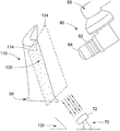
- FIG. 3 depicts a schematic view of a portion of the fluid flow orifice locating system for locating fluid flow orifices on a component of a turbomachine, in accordance with an exemplary embodiment
- FIG. 4 depicts a flow chart illustrating a method for locating fluid flow orifices on a component of a turbomachine, in accordance with an exemplary embodiment.
- Turbomachine system 2 includes a turbomachine 4 having a compressor portion 6 connected to a turbine portion 8 .
- Compressor portion 6 includes an inlet 10 .
- Compressor portion 6 includes a plurality of stages (not separately labeled). Each stage includes a plurality of stationary nozzles, and a plurality of and rotating buckets or blades (also not separately labeled).
- Turbine portion 8 includes a plurality of stages 9 . Each stage 9 includes a corresponding plurality of nozzles, such as shown at 12 , and a plurality of rotating buckets or blades, such as shown at 13 .
- Turbine portion 8 also includes an outlet 14 .
- a combustor assembly 20 fluidically connects compressor portion 6 and turbine portion 8 .
- Combustor assembly 20 includes one or more combustors 22 . Products of combustion pass from each combustor 22 into turbine portion 8 through a corresponding transition piece (not shown). The products of combustion pass along a hot gas path 25 interacting with plurality of stages 9 .
- Turbomachine system 2 is further shown to include an intake system 24 fluidically connected to inlet 10 and a load 26 that may be operatively connected to turbine portion 8 . It should be understood that load 26 may also be connected to compressor portion 6 .
- An exhaust system 28 is fluidically connected to outlet 14 of turbine portion 8 . Exhaust system 28 receives and conditions exhaust gases passing from turbomachine 4 .
- Turbomachine system 2 also includes a fluid flow orifice locating system 40 for locating fluid flow orifices on a turbomachine component.
- fluid flow orifice locating system 40 includes a housing 50 having a processing chamber 54 .
- a component holding fixture 59 is located in processing chamber 54 .
- component holding fixture 59 retains and positions a turbomachine component for processing in fluid flow orifice locating system 40 .
- a light source 70 which may take the form of one or more white light emitting diodes (LEDs) 72 and an image capture device 80 are arranged in processing chamber 54 .
- LEDs white light emitting diodes
- light source 70 may take on a variety of forms including incandescent bulbs, Organic Light Emitting Diodes (OLEDs), and the like. Also, it should be understood that the number of components that make up light source 70 may vary.
- Image capture device 80 may take the form of a digital camera 82 having a lens 84 .
- Digital camera 82 is mounted to a multi-axis manipulator 85 and is operably connected to a controller 90 which, as will be detailed more fully below, processes images to determine a location of fluid flow orifices on a turbomachine component.
- a processing system 99 may also be arranged in processing chamber 54 .
- Processing system 99 may include one or more of a fluid flow orifice clearing system, a masking system, a braze injection system and a mask clearing system.
- Processing system 99 may also support image capture device 80 .
- a turbomachine component 110 is secured to component holding fixture 59 .
- Turbomachine component 110 may take the form of a compressor portion component such as a compressor nozzle and/or compressor bucket or a turbine portion component such as a turbine nozzle and/or turbine bucket.
- Turbomachine component 110 includes a surface 114 having plurality of fluid flow orifices 120 . Fluid flow orifices 120 provide passage of a cooling fluid from an internal portion (not separately labeled) of turbomachine component 110 .
- light source 70 is arranged at a non-perpendicular angle 130 relative to surface 114 . In accordance with an aspect of an exemplary embodiment, light source 70 is directed upwardly onto surface 114 .
- Multi-axis manipulator 85 guides image capture device 80 to establish a field of view (FOV) 134 that encompasses all of surface 114 .
- FOV field of view
- a method 150 of locating fluid flow orifices 120 on turbomachine component 110 In block 160 light source 70 is activated to illuminate surface 114 of turbomachine component 110 . The illumination of surface 114 creates contrast differences caused by shadows cast by the plurality of fluid flow orifices 120 .
- An image is captured by image capture device 80 in block 180 .
- controller 90 compares the captured image to stored data.
- the stored data may be a previously captured image and/or engineering or computer-aided design (CAD) data for turbomachine component 110 .
- CAD data may include both two dimensional (2D) and three-dimensional (3D) drawing files.
- Controller 90 creates a fluid flow orifice map 210 in block 220 .
- Fluid flow orifice map 210 comprises a computer generated data file including a location, in space, defined by x, y, and z coordinates for each of the plurality of fluid flow orifices 120 .
- the fluid flow orifice map should not be understood to necessitate a mapping of fluid flow orifices relative to other fluid flow orifices 120 on surface 114 , but rather represent a location, in space, of each fluid flow orifice on surface 114 .
- controller 90 may also determine a location of each fluid flow orifice 120 relative to others of the fluid flow orifices 120 if desired.
- turbomachine component 110 may be subjected to a processing step by processing system 99 , in block 240 .
- processing system 99 may perform one or more of a fluid flow orifice clearing operation, a masking operation, a braze injection operation and/or a mask removal operation.
- controller 90 may also determine a location of fluid flow orifices 120 that may be covered by masking or brazing by evaluating contrasts on surface 114 to further aid in processing.
- Processing system 99 may also perform additional operations as selected by a user.
- the exemplary embodiments describe a system that accurately locates fluid flow orifices on a turbomachine component.
- the fluid flow orifices are mapped with x, y, and z coordinates which may be provided to a processing system.
- the above-described system reduces processing time and may identify all fluid flow orifices in a single operation. Further, the system reduces the need for multiple operator interactions such that processing is substantially automated once a component is mounted in the processing chamber.
Landscapes
- Engineering & Computer Science (AREA)
- Multimedia (AREA)
- Signal Processing (AREA)
- Physics & Mathematics (AREA)
- General Physics & Mathematics (AREA)
- Structures Of Non-Positive Displacement Pumps (AREA)
Abstract
Description
Claims (14)
Applications Claiming Priority (2)
| Application Number | Priority Date | Filing Date | Title |
|---|---|---|---|
| TR201500931 | 2015-01-28 | ||
| TR2015/00931 | 2015-01-28 |
Publications (2)
| Publication Number | Publication Date |
|---|---|
| US20160223315A1 US20160223315A1 (en) | 2016-08-04 |
| US10859367B2 true US10859367B2 (en) | 2020-12-08 |
Family
ID=56554048
Family Applications (1)
| Application Number | Title | Priority Date | Filing Date |
|---|---|---|---|
| US15/004,277 Active 2038-09-07 US10859367B2 (en) | 2015-01-28 | 2016-01-22 | System and method for locating fluid flow orifices on a component |
Country Status (1)
| Country | Link |
|---|---|
| US (1) | US10859367B2 (en) |
Cited By (2)
| Publication number | Priority date | Publication date | Assignee | Title |
|---|---|---|---|---|
| US11407067B2 (en) * | 2018-06-29 | 2022-08-09 | Pratt & Whitney Canada Corp. | Method for repairing a part |
| US12049832B2 (en) | 2022-12-28 | 2024-07-30 | Ge Infrastructure Technology Llc | Cooling hole positioning systems and methods |
Citations (17)
| Publication number | Priority date | Publication date | Assignee | Title |
|---|---|---|---|---|
| US5583948A (en) | 1993-10-18 | 1996-12-10 | Sumitomo Wiring Systems, Ltd. | Connecting element inspecting method and connecting element inspecting device |
| US5859704A (en) * | 1996-08-08 | 1999-01-12 | General Electric Company | Superficial laser induced fluorescence |
| US20020089561A1 (en) * | 2000-11-09 | 2002-07-11 | Therics, Inc. | Method and apparatus for obtaining information about a dispensed fluid, such as using optical fiber to obtain diagnostic information about a fluid at a printhead during printing |
| US20040253105A1 (en) | 2000-12-15 | 2004-12-16 | Janakiraman Vaidyanathan | Process and apparatus for locating coated cooling holes on turbine vanes |
| US7305118B2 (en) | 2004-10-22 | 2007-12-04 | Pratt & Whitney Canada Corp. | Illumination system for measurement system |
| US20090145504A1 (en) * | 2007-12-11 | 2009-06-11 | Colletti Michael J | Fuel distribution tube for direct injection fuel rail assemblies |
| US7578178B2 (en) | 2007-09-28 | 2009-08-25 | United Technologies Corporation | Method of inspecting turbine internal cooling features using non-contact scanners |
| US20090220349A1 (en) | 2005-09-26 | 2009-09-03 | Hans-Thomas Bolms | Method for Producing a Gas Turbine Component Which is to be Coated, With Exposed Holes, Device for Carrying Out the Method, and Coatable Turbine Blade with Film Cooling Holes |
| US20090297336A1 (en) * | 2007-08-21 | 2009-12-03 | General Electric Company | Online systems and methods for thermal inspection of parts |
| US20110267451A1 (en) * | 2010-05-03 | 2011-11-03 | United Technologies Corporation | On-the-fly dimensional imaging inspection |
| US8244025B2 (en) | 2006-03-20 | 2012-08-14 | Siemens Energy, Inc. | Method of coalescing information about inspected objects |
| US20130163849A1 (en) * | 2010-09-14 | 2013-06-27 | Ronny Jahnke | Apparatus and method for automatic inspection of through-holes of a component |
| US8477154B2 (en) | 2006-03-20 | 2013-07-02 | Siemens Energy, Inc. | Method and system for interactive virtual inspection of modeled objects |
| US20140320861A1 (en) * | 2013-04-26 | 2014-10-30 | Becton, Dickinson And Company | Methods and systems for the collection of light using total internal reflectance |
| US20150161778A1 (en) * | 2013-12-06 | 2015-06-11 | Rolls-Royce Corporation | Thermographic inspection techniques |
| US20150283531A1 (en) * | 2012-04-18 | 2015-10-08 | Biofire Diagnostics, Llc | Microspotting Device |
| US20150366438A1 (en) * | 2012-02-06 | 2015-12-24 | Vantage Surgical Systems Inc. | Methods and steering device for minimally invasive visualization surgery systems |
-
2016
- 2016-01-22 US US15/004,277 patent/US10859367B2/en active Active
Patent Citations (20)
| Publication number | Priority date | Publication date | Assignee | Title |
|---|---|---|---|---|
| US5583948A (en) | 1993-10-18 | 1996-12-10 | Sumitomo Wiring Systems, Ltd. | Connecting element inspecting method and connecting element inspecting device |
| US5859704A (en) * | 1996-08-08 | 1999-01-12 | General Electric Company | Superficial laser induced fluorescence |
| US20020089561A1 (en) * | 2000-11-09 | 2002-07-11 | Therics, Inc. | Method and apparatus for obtaining information about a dispensed fluid, such as using optical fiber to obtain diagnostic information about a fluid at a printhead during printing |
| US20040253105A1 (en) | 2000-12-15 | 2004-12-16 | Janakiraman Vaidyanathan | Process and apparatus for locating coated cooling holes on turbine vanes |
| US6909800B2 (en) | 2000-12-15 | 2005-06-21 | United Technologies Corporation | Process and apparatus for locating coated cooling holes on turbine vanes |
| US7388980B2 (en) | 2000-12-15 | 2008-06-17 | United Technologies Corporation | Process and apparatus for locating coated cooling holes on turbine vanes |
| US7305118B2 (en) | 2004-10-22 | 2007-12-04 | Pratt & Whitney Canada Corp. | Illumination system for measurement system |
| US20090220349A1 (en) | 2005-09-26 | 2009-09-03 | Hans-Thomas Bolms | Method for Producing a Gas Turbine Component Which is to be Coated, With Exposed Holes, Device for Carrying Out the Method, and Coatable Turbine Blade with Film Cooling Holes |
| US8414264B2 (en) | 2005-09-26 | 2013-04-09 | Siemens Aktiengesellschaft | Method for producing a gas turbine component which is to be coated, with exposed holes, device for carrying out the method, and coatable turbine blade with film cooling holes |
| US8477154B2 (en) | 2006-03-20 | 2013-07-02 | Siemens Energy, Inc. | Method and system for interactive virtual inspection of modeled objects |
| US8244025B2 (en) | 2006-03-20 | 2012-08-14 | Siemens Energy, Inc. | Method of coalescing information about inspected objects |
| US20090297336A1 (en) * | 2007-08-21 | 2009-12-03 | General Electric Company | Online systems and methods for thermal inspection of parts |
| US7578178B2 (en) | 2007-09-28 | 2009-08-25 | United Technologies Corporation | Method of inspecting turbine internal cooling features using non-contact scanners |
| US20090145504A1 (en) * | 2007-12-11 | 2009-06-11 | Colletti Michael J | Fuel distribution tube for direct injection fuel rail assemblies |
| US20110267451A1 (en) * | 2010-05-03 | 2011-11-03 | United Technologies Corporation | On-the-fly dimensional imaging inspection |
| US20130163849A1 (en) * | 2010-09-14 | 2013-06-27 | Ronny Jahnke | Apparatus and method for automatic inspection of through-holes of a component |
| US20150366438A1 (en) * | 2012-02-06 | 2015-12-24 | Vantage Surgical Systems Inc. | Methods and steering device for minimally invasive visualization surgery systems |
| US20150283531A1 (en) * | 2012-04-18 | 2015-10-08 | Biofire Diagnostics, Llc | Microspotting Device |
| US20140320861A1 (en) * | 2013-04-26 | 2014-10-30 | Becton, Dickinson And Company | Methods and systems for the collection of light using total internal reflectance |
| US20150161778A1 (en) * | 2013-12-06 | 2015-06-11 | Rolls-Royce Corporation | Thermographic inspection techniques |
Non-Patent Citations (1)
| Title |
|---|
| T. Ninomiya et al., "Automatic 21/2D Shape Inspection System for Via-Hole Fillings of Green Sheets by Shadow Image Analysis" IEEE pp. 515-520 1989. |
Cited By (2)
| Publication number | Priority date | Publication date | Assignee | Title |
|---|---|---|---|---|
| US11407067B2 (en) * | 2018-06-29 | 2022-08-09 | Pratt & Whitney Canada Corp. | Method for repairing a part |
| US12049832B2 (en) | 2022-12-28 | 2024-07-30 | Ge Infrastructure Technology Llc | Cooling hole positioning systems and methods |
Also Published As
| Publication number | Publication date |
|---|---|
| US20160223315A1 (en) | 2016-08-04 |
Similar Documents
| Publication | Publication Date | Title |
|---|---|---|
| US11536670B2 (en) | System and method for engine inspection | |
| CN110462169B (en) | Gas Turbine Engine Maintenance Tools | |
| CN110249212B (en) | Gas Turbine Engine Maintenance Methods | |
| US7574035B2 (en) | System and method for inspection of hole location on turbine airfoils | |
| US8380338B2 (en) | Method and apparatus for stripping holes in a metal substrate | |
| CN110524537A (en) | Systems and methods for controlling a robotic arm | |
| US20150138342A1 (en) | System and method to determine visible damage | |
| CN112639251A (en) | Automated identification of cooling holes and tool path generation | |
| US12345167B2 (en) | System and method of using a tool assembly | |
| US10048133B2 (en) | Thermal inspection system | |
| US10859367B2 (en) | System and method for locating fluid flow orifices on a component | |
| EP1760427B1 (en) | Methods for measuring the nozzle flow area between gas turbine engine vanes | |
| US10713773B2 (en) | System and method for identifying a condition of rotary machine components | |
| US11340184B2 (en) | Engine component performance inspection sleeve and method of inspecting engine component | |
| US8937628B2 (en) | Mapping of a contour shape to an X and Y coordinate system | |
| US11010887B2 (en) | Automated distress ranking system | |
| US20150343566A1 (en) | Remote feature measurement | |
| US10189045B2 (en) | Blackbody material application system for a turbine | |
| FR3093540B1 (en) | DOUBLE-FLOW GAS TURBOMACHINE WITH THERMAL EXCHANGER ARM | |
| US20180321113A1 (en) | System and methods of inspecting a component |
Legal Events
| Date | Code | Title | Description |
|---|---|---|---|
| AS | Assignment |
Owner name: GENERAL ELECTRIC COMPANY, NEW YORK Free format text: ASSIGNMENT OF ASSIGNORS INTEREST;ASSIGNORS:OZTURK, YUSUF EREN;LOMAS, JONATHAN MATTHEW;REID, THOMAS ROBERT;SIGNING DATES FROM 20150112 TO 20150115;REEL/FRAME:037560/0031 |
|
| STCV | Information on status: appeal procedure |
Free format text: APPEAL BRIEF (OR SUPPLEMENTAL BRIEF) ENTERED AND FORWARDED TO EXAMINER |
|
| STPP | Information on status: patent application and granting procedure in general |
Free format text: NON FINAL ACTION MAILED |
|
| STPP | Information on status: patent application and granting procedure in general |
Free format text: RESPONSE TO NON-FINAL OFFICE ACTION ENTERED AND FORWARDED TO EXAMINER |
|
| STPP | Information on status: patent application and granting procedure in general |
Free format text: FINAL REJECTION MAILED |
|
| STPP | Information on status: patent application and granting procedure in general |
Free format text: RESPONSE AFTER FINAL ACTION FORWARDED TO EXAMINER |
|
| STPP | Information on status: patent application and granting procedure in general |
Free format text: PUBLICATIONS -- ISSUE FEE PAYMENT VERIFIED |
|
| STCF | Information on status: patent grant |
Free format text: PATENTED CASE |
|
| AS | Assignment |
Owner name: GE INFRASTRUCTURE TECHNOLOGY LLC, SOUTH CAROLINA Free format text: ASSIGNMENT OF ASSIGNORS INTEREST;ASSIGNOR:GENERAL ELECTRIC COMPANY;REEL/FRAME:065727/0001 Effective date: 20231110 |
|
| MAFP | Maintenance fee payment |
Free format text: PAYMENT OF MAINTENANCE FEE, 4TH YEAR, LARGE ENTITY (ORIGINAL EVENT CODE: M1551); ENTITY STATUS OF PATENT OWNER: LARGE ENTITY Year of fee payment: 4 |