US10858524B2 - Protective film forming resin agent and laser processing method - Google Patents
Protective film forming resin agent and laser processing method Download PDFInfo
- Publication number
- US10858524B2 US10858524B2 US15/352,053 US201615352053A US10858524B2 US 10858524 B2 US10858524 B2 US 10858524B2 US 201615352053 A US201615352053 A US 201615352053A US 10858524 B2 US10858524 B2 US 10858524B2
- Authority
- US
- United States
- Prior art keywords
- protective film
- film forming
- particulates
- major axis
- metal oxide
- Prior art date
- Legal status (The legal status is an assumption and is not a legal conclusion. Google has not performed a legal analysis and makes no representation as to the accuracy of the status listed.)
- Active, expires
Links
Images


Classifications
-
- C—CHEMISTRY; METALLURGY
- C09—DYES; PAINTS; POLISHES; NATURAL RESINS; ADHESIVES; COMPOSITIONS NOT OTHERWISE PROVIDED FOR; APPLICATIONS OF MATERIALS NOT OTHERWISE PROVIDED FOR
- C09D—COATING COMPOSITIONS, e.g. PAINTS, VARNISHES OR LACQUERS; FILLING PASTES; CHEMICAL PAINT OR INK REMOVERS; INKS; CORRECTING FLUIDS; WOODSTAINS; PASTES OR SOLIDS FOR COLOURING OR PRINTING; USE OF MATERIALS THEREFOR
- C09D7/00—Features of coating compositions, not provided for in group C09D5/00; Processes for incorporating ingredients in coating compositions
- C09D7/40—Additives
- C09D7/60—Additives non-macromolecular
- C09D7/61—Additives non-macromolecular inorganic
-
- C—CHEMISTRY; METALLURGY
- C09—DYES; PAINTS; POLISHES; NATURAL RESINS; ADHESIVES; COMPOSITIONS NOT OTHERWISE PROVIDED FOR; APPLICATIONS OF MATERIALS NOT OTHERWISE PROVIDED FOR
- C09D—COATING COMPOSITIONS, e.g. PAINTS, VARNISHES OR LACQUERS; FILLING PASTES; CHEMICAL PAINT OR INK REMOVERS; INKS; CORRECTING FLUIDS; WOODSTAINS; PASTES OR SOLIDS FOR COLOURING OR PRINTING; USE OF MATERIALS THEREFOR
- C09D7/00—Features of coating compositions, not provided for in group C09D5/00; Processes for incorporating ingredients in coating compositions
- C09D7/40—Additives
- C09D7/70—Additives characterised by shape, e.g. fibres, flakes or microspheres
-
- B—PERFORMING OPERATIONS; TRANSPORTING
- B23—MACHINE TOOLS; METAL-WORKING NOT OTHERWISE PROVIDED FOR
- B23K—SOLDERING OR UNSOLDERING; WELDING; CLADDING OR PLATING BY SOLDERING OR WELDING; CUTTING BY APPLYING HEAT LOCALLY, e.g. FLAME CUTTING; WORKING BY LASER BEAM
- B23K26/00—Working by laser beam, e.g. welding, cutting or boring
- B23K26/18—Working by laser beam, e.g. welding, cutting or boring using absorbing layers on the workpiece, e.g. for marking or protecting purposes
-
- C—CHEMISTRY; METALLURGY
- C09—DYES; PAINTS; POLISHES; NATURAL RESINS; ADHESIVES; COMPOSITIONS NOT OTHERWISE PROVIDED FOR; APPLICATIONS OF MATERIALS NOT OTHERWISE PROVIDED FOR
- C09D—COATING COMPOSITIONS, e.g. PAINTS, VARNISHES OR LACQUERS; FILLING PASTES; CHEMICAL PAINT OR INK REMOVERS; INKS; CORRECTING FLUIDS; WOODSTAINS; PASTES OR SOLIDS FOR COLOURING OR PRINTING; USE OF MATERIALS THEREFOR
- C09D129/00—Coating compositions based on homopolymers or copolymers of compounds having one or more unsaturated aliphatic radicals, each having only one carbon-to-carbon double bond, and at least one being terminated by an alcohol, ether, aldehydo, ketonic, acetal, or ketal radical; Coating compositions based on hydrolysed polymers of esters of unsaturated alcohols with saturated carboxylic acids; Coating compositions based on derivatives of such polymers
- C09D129/02—Homopolymers or copolymers of unsaturated alcohols
- C09D129/04—Polyvinyl alcohol; Partially hydrolysed homopolymers or copolymers of esters of unsaturated alcohols with saturated carboxylic acids
-
- C—CHEMISTRY; METALLURGY
- C09—DYES; PAINTS; POLISHES; NATURAL RESINS; ADHESIVES; COMPOSITIONS NOT OTHERWISE PROVIDED FOR; APPLICATIONS OF MATERIALS NOT OTHERWISE PROVIDED FOR
- C09D—COATING COMPOSITIONS, e.g. PAINTS, VARNISHES OR LACQUERS; FILLING PASTES; CHEMICAL PAINT OR INK REMOVERS; INKS; CORRECTING FLUIDS; WOODSTAINS; PASTES OR SOLIDS FOR COLOURING OR PRINTING; USE OF MATERIALS THEREFOR
- C09D201/00—Coating compositions based on unspecified macromolecular compounds
-
- C—CHEMISTRY; METALLURGY
- C08—ORGANIC MACROMOLECULAR COMPOUNDS; THEIR PREPARATION OR CHEMICAL WORKING-UP; COMPOSITIONS BASED THEREON
- C08K—Use of inorganic or non-macromolecular organic substances as compounding ingredients
- C08K3/00—Use of inorganic substances as compounding ingredients
- C08K3/18—Oxygen-containing compounds, e.g. metal carbonyls
- C08K3/20—Oxides; Hydroxides
- C08K3/22—Oxides; Hydroxides of metals
- C08K2003/2237—Oxides; Hydroxides of metals of titanium
- C08K2003/2241—Titanium dioxide
-
- C—CHEMISTRY; METALLURGY
- C08—ORGANIC MACROMOLECULAR COMPOUNDS; THEIR PREPARATION OR CHEMICAL WORKING-UP; COMPOSITIONS BASED THEREON
- C08K—Use of inorganic or non-macromolecular organic substances as compounding ingredients
- C08K3/00—Use of inorganic substances as compounding ingredients
- C08K3/18—Oxygen-containing compounds, e.g. metal carbonyls
- C08K3/20—Oxides; Hydroxides
- C08K3/22—Oxides; Hydroxides of metals
Definitions
- the present invention relates to a protective film forming resin agent to be used for laser processing, and to a laser processing method in which a substrate is subjected to laser processing after coated with the protective film forming resin agent.
- Japanese Patent Laid-Open No. 2013-81951 describes a method in which when subjecting a glass substrate to ablation by applying a laser beam to the glass substrate, the glass substrate is coated with a resin in which fine particles of a metal oxide such as titanium dioxide (TiO 2 ) are dispersed, to form a protective film on the glass substrate, whereby laser beam absorption efficiency is enhanced and processability of the glass substrate is enhanced.
- a metal oxide such as titanium dioxide (TiO 2 )
- a protective film forming resin agent to be used for laser processing including a water-soluble resin, and particulates of a metal oxide which are dispersed in the water-soluble resin and a section of which has an elongated shape having a major axis and a minor axis orthogonal to the major axis.
- the major axis has a length of not more than 500 nm, and the minor axis has a length of 1/10 to 1 ⁇ 5 times the length of the major axis.
- the protective film forming resin agent contains 0.1 to 10% by volume of the particulates of the metal oxide.
- a laser processing method for applying a laser beam to a substrate to perform ablation, the laser processing method including a protective film forming step and a laser processing step.
- the protective film forming step applies a protective film forming resin agent to at least a region on a substrate to be ablated, to form a protective film containing particulates of a metal oxide in the region.
- the laser processing step applies a laser beam to the region formed with the protective film, to ablate the substrate, after the protective film forming step is conducted.
- the protective film forming resin agent In the protective film forming resin agent according to the present invention, particulates of a metal oxide a section of which has an elongated shape having a major axis and a minor axis orthogonal to the major axis are dispersed in a water-soluble resin. Therefore, the protective film forming resin agent is excellent in dispersion properties of the particulates in the resin. For this reason, when the protective film forming resin agent is applied to a workpiece to form a protective film and then the workpiece is subjected to laser processing, absorbance of a laser beam in the protective film is enhanced, and processing efficiency is enhanced. Accordingly, even a substrate showing a low absorbance at the wavelength of the laser beam can be laser processed efficiently. In addition, processing quality is also enhanced, and it is possible to enhance the yield of the product produced by the processing.
- FIG. 1 is a perspective view of an example of a laser processing apparatus
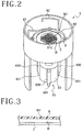
- FIG. 2 is a perspective view of protective film forming means provided with the laser processing apparatus
- FIG. 3 is a partial enlarged view of a plate-shaped workpiece having a surface coated with a protective film
- FIG. 4 is a magnified photo of a protective film formed by use of a protective film forming resin agent according to an embodiment of the present invention
- FIG. 5 is a magnified photo of a protective film formed by use of a protective film forming resin agent according to a prior art
- FIG. 6A is a magnified photo of that part of a substrate coated with a protective film in an embodiment which was ablated under the processing conditions of an output of 3 W, a repetition frequency of 40 kHz, and a feed rate of 150 mm/second;
- FIG. 6B is a magnified photo of that part of a substrate coated with a protective film in a comparative example which was ablated under the same processing conditions as in the case of FIG. 6A ;
- FIG. 7A is a magnified photo of that part of a substrate coated with a protective film in an embodiment which was ablated under the processing conditions of an output of 3 W, a repetition frequency of 40 kHz, and a feed rate of 250 mm/second;
- FIG. 7B is a magnified photo of that part of a substrate coated with a protective film in a comparative example which was ablated under the same processing conditions as in the case of FIG. 7A ;
- FIG. 8A is a magnified photo of that part of a substrate coated with a protective film in an embodiment which was ablated under the processing conditions of an output of 3 W, a repetition frequency of 120 kHz, and a feed rate of 150 mm/second;
- FIG. 8B is a magnified photo of that part of a substrate coated with a protective film in a comparative example which was ablated under the same processing conditions as in the case of FIG. 8A ;
- FIG. 9A is a magnified photo of that part of a substrate coated with a protective film in an embodiment which was ablated under the processing conditions of an output of 3 W, a repetition frequency of 120 kHz, a feed rate of 150 mm/second, and a defocus toward a substrate back side of 30 ⁇ m;
- FIG. 9B is a magnified photo of that part of a substrate coated with a protective film in a comparative example which was ablated under the same processing conditions as in the case of FIG. 9A ;
- FIG. 10 is a graph showing a relationship between wavelength and absorbance of a laser beam.
- a laser processing apparatus 1 shown in FIG. 1 is an apparatus for processing by laser processing means 3 a plate-shaped workpiece W held on a chuck table 2 .
- the plate-shaped workpiece W has a back side attached to a tape T, to which an annular frame F is attached, so that the plate-shaped workpiece W is supported by the frame F through the tape T.
- the laser processing apparatus 1 is provided on a front side ( ⁇ Y direction side) with a cassette placing region 4 , and a cassette 40 in which a plurality of the plate-shaped workpieces W each supported by the frame F are accommodated is placed in the cassette placing region 4 .
- the cassette placing region 4 can be moved upward and downward.
- On a rear side (+Y direction side) of the cassette placing region 4 there is provided a temporary placing region 41 in which the plate-shaped workpiece W supported by the frame F is placed temporarily.
- the temporary placing region 41 is provided with position matching means 42 for matching the plate-shaped workpiece W to a predetermined position.
- carrying-in/out means 43 by which the plate-shaped workpiece W supported by the frame F is carried out from the cassette 40 and carried into the cassette 40 .
- the chuck table 2 can be moved in an X-axis direction, between a mounting/dismounting region A where the plate-shaped workpiece W supported by the frame F mounted onto and dismounted from the chuck table 2 , and a processing region B where laser processing is performed, and the chuck table 2 can also be moved in a Y-axis direction.
- On the +Y direction side of the mounting/dismounting region A there is disposed protective film forming means 6 for forming a protective film on a surface of the plate-shaped workpiece W yet to be subjected to laser processing. As depicted in FIG.
- the protective film forming means 6 includes a holding unit 60 by which the plate-shaped workpiece W supported by the frame F is held and rotated, a resin nozzle 61 through which a liquid resin is dropped onto the plate-shaped workpiece W held on the holding unit 60 , and a cleaning liquid nozzle 62 through which a cleaning liquid is dropped onto the plate-shaped workpiece W.
- the holding unit 60 can be moved upward and downward by a lift unit 63 , and can be rotated under driving of a motor 64 .
- the lift unit 63 includes a plurality of air cylinders 630 fixed to a side surface side of the motor 64 , and rods 631 , such that the motor 64 and the holding unit 60 are moved upward and downward by upward and downward motions of the air cylinders 630 .
- first carrying means 5 by which the plate-shaped workpiece W supported by the frame F is carried between the temporary placing region 41 and the protective film forming means 6 .
- the second carrying means 7 includes a suction holding unit 70 by which the plate-shaped workpiece W is held by suction, a lift unit 71 by which the suction holding unit 70 is moved upward and downward, and an arm unit 72 by which the suction holding unit 70 and the lift unit 71 are moved in the Y-axis direction.
- the laser processing means 3 includes oscillation means 30 for oscillating a laser beam, frequency setting means 31 for setting a repetition frequency of the laser beam, output control means 32 for controlling the output of the laser beam, and focusing means 8 for focusing the laser beam.
- the plate-shaped workpiece W supported by the frame F is carried to the holding unit 60 of the protective film forming means 6 by the first carrying means 5 , and is held with a front side W 1 thereof exposed to the upper side, as depicted in FIG. 2 .
- a protective film forming resin agent 610 is dropped through the resin nozzle 61 shown in FIG. 2 onto the front side W 1 of the plate-shaped workpiece W, and the holding unit 60 is rotated, whereby the protective film forming resin agent 610 is applied to the whole area of the front side W 1 .
- the protective film forming resin agent 610 may be applied by a spin coating method as in the present embodiment, or may be applied by jetting through a slit-shaped nozzle.
- the protective film forming resin agent 610 is applied onto the front side W 1 of the plate-shaped workpiece W, the protective film forming resin agent 610 is dried and solidified by, for example, rotating the holding unit 60 , whereby a protective film 9 depicted in FIG. 3 is formed as a coating.
- the protective film forming resin agent 610 may be dried by irradiation with light from a lamp (e.g., a xenon flash lamp). In that case, it is recommendable to perform irradiation with pulsed light, for avoiding a rise in temperature. Besides, baking by use of a hot plate may also be conducted.
- the lift unit 71 of the second carrying means 7 is lowered, and the plate-shaped workpiece W is held onto the suction holding unit 70 by suction.
- the lift unit 71 is moved upward, and the arm unit 72 is moved in the ⁇ Y direction, whereby the plate-shaped workpiece W is moved to a position on the upper side of the chuck table 2 located in the mounting/dismounting region A, then the lift unit 71 is lowered and the suction holding of the plate-shaped workpiece W by the suction holding unit 70 is released, whereby the plate-shaped workpiece W is placed on and suction held by the chuck table 2 .
- the chuck table 2 is moved in a ⁇ X direction, a street (division line) to be processed is detected, and positional matching between the focusing means 8 and the street in the Y-axis direction is performed. Then, the chuck table 2 is further subjected to processing feed in the X-axis direction, and a laser beam is applied to that region of the front side W 1 of the plate-shaped workpiece W in which the protective film is formed, through the protective film 9 by the focusing means 8 , whereby ablation is conducted along the street.
- the processing feed rate may be, for example, 10 mm/second to 300 mm/second.
- the laser beam may be controlled, for example, to have a wavelength of 355 nm, an output of 0.5 W to 10 W, and a repetition frequency of 10 kHz to 200 kHz.
- the protective film 9 formed as a coating by the protective film forming means 6 will be described in detail below.
- the protective film forming resin agent 610 dropped as shown in FIG. 2 is configured to have a metal oxide dispersed in a water-soluble resin.
- the water-soluble resin to be used here include polyvinyl alcohol (PVA) and polyvinylpyrrolidone (PVP), other examples being polyethylene glycol, polyethylene oxide, polyethylene imine, carboxymethyl cellulose, hydroxyethyl cellulose, etc.
- Polyvinyl alcohol and polyvinylpyrrolidone may each have a viscosity of 20 cp to 400 cp.
- the metal oxide may be particulates of titanium dioxide (TiO 2 ), for example.
- metal oxide than titanium dioxide examples include Fe 2 O 3 , ZnO, CeO 2 , CuO, Cu 2 O, and MgO. These metal oxides are selected based on the absorbance of the laser beam at the wavelength of the laser beam used at the time of processing.
- Photo 100 in FIG. 4 shows, in a magnified form, the protective film 9 formed by use of the protective film forming resin agent 610 according to the present invention.
- the particulates of the metal oxide are not circular, but are formed in an indefinite elongated shape having a major axis and a minor axis orthogonal to the major axis.
- the elongated shape includes ellipses, polygons, acicular shapes and the like, the orientation of which is irregular.
- the elongated shapes include highly anisotropic shapes.
- the major axis has a length of not more than 500 nm
- the minor axis has a length of 1/10 to 1 ⁇ 5 times the length of the major axis.
- the length of the major axis is preferably 1 nm to 100 nm, more preferably 20 nm to 50 nm. If the length of the major axis exceeds 500 nm, the effect of scattering of the laser beam becomes predominant, which is undesirable for laser processing.
- the concentration of the particulates of the metal oxide is preferably 0.1 to 10% by volume, more preferably 0.5 to 5% by volume, and further preferably 1 to 2.5% by volume, based on the total volume (the volume of the metal oxide plus the volume of the resin). Note that when the protective film 9 is used as an etching mask at the time of plasma dicing (dry etching), plasma resistance can be enhanced.
- Particulates of a metal oxide (titanium oxide (TiO 2 )) shown in photo 100 in FIG. 4 were dispersed in water, to form a dispersion (TiO 2 concentration: 30% by weight).
- the dispersion was mixed into an aqueous solution of polyvinyl alcohol (GL-05, made by The Nippon Synthetic Chemical Industry Co., Ltd.), followed by stirring with a stirrer, to prepare a sample (water-soluble resin) of an Example in which the particulates of TiO 2 with an elongated shape were dispersed in the aqueous polyvinyl alcohol solution.
- the particulates of TiO 2 had a particle diameter (major axis length) of 20 nm to 50 nm.
- the TiO 2 particulates occupied 62% of the total volume including the water-soluble resin.
- particulates of titanium oxide having a substantially spherical shape instead of an elongated shape as shown in photo 101 in FIG. 5 were dispersed in water to form a dispersion (TiO 2 concentration: 30% by weight), and the dispersion was mixed into an aqueous solution of water-soluble polyvinyl alcohol (GL-05, made by The Nippon Synthetic Chemical Industry Co., Ltd.), followed by stirring with a stirrer, to prepare a sample (water-soluble resin) of the Comparative Example in which the particulates of TiO 2 were dispersed in the aqueous polyvinyl alcohol solution.
- the TiO 2 particulates occupied 80% of the total volume including the water-soluble resin.
- Each of the water-soluble resin of the Example and the water-soluble resin of the Comparative Example was applied to a surface of a glass to form a protective film, and a laser beam was applied to the glass along a street on the glass, to perform ablation.
- FIGS. 6A to 9B are photos of those parts of the glasses coated respectively with the protective films of the Example and the Comparative Example which were subjected to ablation by use of the laser processing apparatus 1 depicted in FIG. 1 .
- Photos 201 , 301 , 401 , and 501 in FIGS. 6A to 9A show the results of processing in the Examples, whereas photos 202 , 302 , 402 , and 502 in FIGS. 6B to 9B show the results of processing in the Comparative Examples.
- Each of photos 201 , 301 , 401 , and 501 in FIGS. 6A to 9A is obtained by coating a part (left side) on the left side of a boundary 601 , 603 , 605 , or 607 of a glass surface with only the liquid resin to form a protective film and coating a part (right side) on the right side of the boundary 601 , 603 , 605 , or 607 of the glass surface with the protective film of the Example, subjecting the respective parts to ablation, and photographing the processed state of the parts.
- 6B to 9B was obtained by coating a part (left side) on the left side of a boundary 602 , 604 , 606 , or 608 of a glass surface with only the liquid resin to form a protective film and coating a part (right side) on the right side of the boundary 602 , 604 , 606 , or 608 of the glass surface with a protective film forming resin agent containing the substantially spherical titanium oxide particulates dispersed therein to form a protective film, subjecting the respective parts to ablation, and photographing the processed state of the parts.
- FIGS. 6A and 6B show the results of processing under the processing conditions of a repetition frequency of 40 kHz and a feed rate of the chuck table 2 depicted in FIG. 1 of 150 mm/second.
- photo 201 in FIG. 6A the part coated with the protective film not containing titanium oxide and photographed on the left side of the boundary 601 has a processed groove 203 which is not rectilinear, and many chippings are seen generated on both sides of the processed groove 203 .
- 6A has no chippings on either side of a processed groove 204 , and the processed groove 204 is formed to be rectilinear, verifying a high processing quality.
- the resin agent constituting the protective film was much scattered on both sides of the processed groove 204 , verifying that the processing was performed efficiently.
- the part coated with the protective film not containing titanium oxide and photographed on the left side of the boundary 602 has a processed groove 205 which is not rectilinear, and many chippings are seen generated on both sides of the processed groove 205 .
- the part coated with the protective film containing the substantially spherical titanium particulates dispersed therein and photographed on the right side of the boundary 602 in photo 202 in FIG. 6B is formed to be rectilinear.
- the particulates with the indefinite elongated shape give an enhanced processing quality and an enhanced processing efficiency as compared to the particulates with the substantially spherical shape.
- FIGS. 7A and 7B show the results of processing under the processing conditions of a repetition frequency of 40 kHz and a feed rate of the chuck table 2 depicted in FIG. 1 of 250 mm/second.
- photo 301 in FIG. 7A the part coated with the protective film not containing titanium oxide and photographed on the left side of the boundary 603 has a processed groove 303 not formed rectilinearly, and chippings are seen generated on both sides of the processed groove 303 .
- the processed groove 304 has no chippings on either side of a processed groove 304 , and the processed groove 304 is formed to be rectilinear, verifying a high processing quality.
- the resin agent constituting the protective film is much scattered on both sides of the processed groove 304 , verifying that the processing was performed efficiently.
- the part coated with the protective film not containing titanium oxide and photographed on the left side of the boundary 604 has a processed groove 305 not formed rectilinearly, and many chippings are seen generated on both sides of the processed groove 305 .
- the part coated with the protective film containing the substantially spherical titanium oxide particulates dispersed therein and photographed on the right side of the boundary 604 has a processed groove 306 formed to be rectilinear.
- the particulates with the elongated shape can give an enhanced processing quality as compared to the particulates with the substantially spherical shape.
- FIGS. 8A and 8B show the results of processing under the processing conditions of a repetition frequency of 120 kHz and a feed rate of the chuck table 2 depicted in FIG. 1 of 150 mm/second.
- the part coated with the protective film not containing titanium oxide and photographed on the left side of the boundary 605 has a processed groove 403 having a small groove width.
- the part coated with the protective film of the Example and photographed on the right side of the boundary 605 in photo 401 in FIG. 8A has a processed groove 404 having a large groove width, and shows the protective film forming resin agent much scattered on both sides of the processed groove 404 , verifying that the processing was performed efficiently.
- the part coated with the protective film not containing titanium oxide and photographed on the left side of the boundary 606 has a processed groove 405 having a small groove width.
- the part coated with the protective film containing the substantially spherical titanium oxide particulates dispersed therein and photographed on the right side of the boundary 606 in photo 402 in FIG. 8B has a processed groove 406 greater in groove width than the processed groove 405 .
- the processed groove 406 in FIG. 8B is small in groove width, verifying that the processed groove 404 in FIG. 8A was processed efficiently. Therefore, it was confirmed that in regard of titanium oxide contained in the protective film, the particulates with the elongated shape give an enhanced processing quality as compared with the particulates with the substantially spherical shape.
- FIGS. 9A and 9B show the results of processing under the processing conditions of a repetition frequency of 120 kHz, a feed rate of the chuck table 2 depicted in FIG. 1 of 150 mm/second, and a defocus of the focal depth of the laser beam set to 30 ⁇ m toward the back side from the front surface.
- the part coated with the protective film not containing titanium oxide and photographed on the left side of the boundary 607 has no continuous processed groove formed, showing that ablation could not be achieved.
- the part coated with the protective film of the Example and photographed on the right side of the boundary 607 in photo 501 in FIG. 9A has a processed groove 504 formed in a continuous rectilinear shape, verifying that ablation was performed.
- the processed groove 504 is large in groove width, which shows that the processing was conducted efficiently.
- the part coated with the protective film not containing titanium oxide and photographed on the left side of the boundary 608 has no continuous processed groove formed, showing that ablation could not be achieved.
- the part coated with the protective film containing the substantially spherical titanium oxide particulates dispersed therein and photographed on the right side of the boundary 608 in photo 502 in FIG. 9B has a processed groove 506 confirmed to be formed in a continuous rectilinear shape.
- the processed groove 506 in FIG. 9B is small in groove width, verifying that the processed groove 504 in FIG. 9A was processed efficiently.
- the particulates with the elongated shape such as an elliptical shape give an enhanced processing quality as compared to the particulates with the substantially spherical shape.
- Table 1 given below shows average values of laser burn generation rate, chipping generation rate, and yield, in the case where a workpiece having a film of polyimide formed on silicon (hereinafter referred to as “this workpiece”) was subjected to laser processing.
- This workpiece a workpiece having a film of polyimide formed on silicon (hereinafter referred to as “this workpiece”) was subjected to laser processing.
- the processing conditions were as follows.
- No metal oxide indicates the case where a liquid resin not containing particulates of a metal oxide was applied to this workpiece to form a protective film
- Comparative Example indicates the case where a protective film forming resin agent containing substantially spherical particulates of titanium oxide dispersed therein was applied to this workpiece to form a protective film
- Present Invention indicates the case where a protective film forming resin agent containing titanium oxide particulates with an elongated shape dispersed therein was applied to this workpiece to form a protective film.
- laser burn is a phenomenon in which a laser beam is reflected by scattered debris of protective film and is applied to a position where laser light application should not occur.
- a chipping generation rate of 0.00% in the Present Invention indicates that the chipping generation rate is below the detection limit.
- a graph shown in FIG. 10 shows the results of determination of relationship between wavelength and absorbance of a laser beam, by measurement of absorption spectrum by use of a spectrophotometer V-670 made by JASCO Corporation, for each of a sapphire substrate (reference), a resin agent containing substantially spherical particulates of titanium oxide dispersed therein, and a resin agent containing titanium oxide particulates with an elongated shape dispersed therein.
- the sapphire substrate (reference) showed a low absorbance regardless of the value of wavelength.
- the resin agents containing the titanium oxide particulates dispersed therein showed an absorbance lowered more as the wavelength was longer. In this case, the rate of lowering in absorbance with an increase in wavelength was lower, and hence a higher absorbance can be maintained, in the case where the particulates of titanium oxide constituting the resin agent had an elongated shape than in the case where the particulates had a substantially spherical shape.
Landscapes
- Chemical & Material Sciences (AREA)
- Engineering & Computer Science (AREA)
- Organic Chemistry (AREA)
- Life Sciences & Earth Sciences (AREA)
- Materials Engineering (AREA)
- Wood Science & Technology (AREA)
- Plasma & Fusion (AREA)
- Optics & Photonics (AREA)
- Physics & Mathematics (AREA)
- Mechanical Engineering (AREA)
- Inorganic Chemistry (AREA)
- Laser Beam Processing (AREA)
- Health & Medical Sciences (AREA)
- Chemical Kinetics & Catalysis (AREA)
- Medicinal Chemistry (AREA)
- Polymers & Plastics (AREA)
Abstract
Description
| TABLE 1 | |||||
| Laser burn | Chipping | ||||
| generation | generation | ||||
| rate (%) | rate (%) | Yield (%) | |||
| No metal oxide | 0.41 | 0.25 | 95.77 | ||
| Comparative Example | 0.28 | 0.19 | 94.86 | ||
| Present Invention | 0.04 | 0.00 | 97.05 | ||
Claims (7)
Priority Applications (1)
| Application Number | Priority Date | Filing Date | Title |
|---|---|---|---|
| US15/352,053 US10858524B2 (en) | 2016-11-15 | 2016-11-15 | Protective film forming resin agent and laser processing method |
Applications Claiming Priority (1)
| Application Number | Priority Date | Filing Date | Title |
|---|---|---|---|
| US15/352,053 US10858524B2 (en) | 2016-11-15 | 2016-11-15 | Protective film forming resin agent and laser processing method |
Publications (2)
| Publication Number | Publication Date |
|---|---|
| US20180134905A1 US20180134905A1 (en) | 2018-05-17 |
| US10858524B2 true US10858524B2 (en) | 2020-12-08 |
Family
ID=62107251
Family Applications (1)
| Application Number | Title | Priority Date | Filing Date |
|---|---|---|---|
| US15/352,053 Active 2038-03-16 US10858524B2 (en) | 2016-11-15 | 2016-11-15 | Protective film forming resin agent and laser processing method |
Country Status (1)
| Country | Link |
|---|---|
| US (1) | US10858524B2 (en) |
Citations (4)
| Publication number | Priority date | Publication date | Assignee | Title |
|---|---|---|---|---|
| JP2013081951A (en) | 2011-10-06 | 2013-05-09 | Disco Corp | Glass substrate ablation method |
| US20140175070A1 (en) * | 2012-12-25 | 2014-06-26 | Disco Corporation | Laser processing method and fine particle layer forming agent |
| US9090783B2 (en) * | 2004-11-12 | 2015-07-28 | Tokyo Ohka Kogyo Co., Ltd. | Protective film agent for laser dicing and wafer processing method using the protective film agent |
| US20170067137A1 (en) * | 2015-09-07 | 2017-03-09 | Seiko Epson Corporation | Titanium sintered body and ornament |
-
2016
- 2016-11-15 US US15/352,053 patent/US10858524B2/en active Active
Patent Citations (4)
| Publication number | Priority date | Publication date | Assignee | Title |
|---|---|---|---|---|
| US9090783B2 (en) * | 2004-11-12 | 2015-07-28 | Tokyo Ohka Kogyo Co., Ltd. | Protective film agent for laser dicing and wafer processing method using the protective film agent |
| JP2013081951A (en) | 2011-10-06 | 2013-05-09 | Disco Corp | Glass substrate ablation method |
| US20140175070A1 (en) * | 2012-12-25 | 2014-06-26 | Disco Corporation | Laser processing method and fine particle layer forming agent |
| US20170067137A1 (en) * | 2015-09-07 | 2017-03-09 | Seiko Epson Corporation | Titanium sintered body and ornament |
Non-Patent Citations (2)
| Title |
|---|
| Mortensen, A. ((2007). Concise Encyclopedia of Composite Materials (2nd Edition)-Biomimetic Materials: Properties and Processing.) (Year: 2007). * |
| Mortensen, A. ((2007). Concise Encyclopedia of Composite Materials (2nd Edition)—Biomimetic Materials: Properties and Processing.) (Year: 2007). * |
Also Published As
| Publication number | Publication date |
|---|---|
| US20180134905A1 (en) | 2018-05-17 |
Similar Documents
| Publication | Publication Date | Title |
|---|---|---|
| US10692721B2 (en) | Wafer processing method for reforming protective film | |
| TWI691375B (en) | Detection method of protective film for laser processing | |
| CN100400215C (en) | Control method for laser processing | |
| JP4490883B2 (en) | Laser processing apparatus and laser processing method | |
| JP6647829B2 (en) | Laser processing equipment | |
| CN102446735B (en) | Dividing method | |
| TWI477340B (en) | Laser processing methods, laser processing and laser processing equipment | |
| CN104576530B (en) | The processing method of chip | |
| US7776721B2 (en) | Laser processing method for gallium arsenide wafer | |
| JP6614696B2 (en) | Protective film forming resin agent and laser processing method | |
| CN1800258A (en) | Protective film agent for laser dicing and wafer processing method using the protective film agent | |
| CN111971145B (en) | Ultra-precision blade machining method using femtosecond laser | |
| CN108373694B (en) | Resin agent for forming protective film and laser processing method | |
| WO2020100403A1 (en) | Protective film forming agent for plasma dicing and method for manufacturing semiconductor chip | |
| CN103035570B (en) | Ablation method | |
| CN105304563A (en) | Processing method of package substrate | |
| JP2021126659A (en) | Laser processing device | |
| CN103658986A (en) | Laser processing device and protecting film covering method | |
| JP7033485B2 (en) | Cutting blade shaping method | |
| US10858524B2 (en) | Protective film forming resin agent and laser processing method | |
| JP2021197482A (en) | Processing method of workpiece, method for manufacturing workpiece with protective film, and protective film agent for laser dicing | |
| TWI890826B (en) | Laser processing equipment | |
| JPS62104692A (en) | Laser beam device | |
| KR102541722B1 (en) | Protective film forming resin and laser machining method | |
| TWI729017B (en) | Resin agent for forming protective film and laser processing method |
Legal Events
| Date | Code | Title | Description |
|---|---|---|---|
| AS | Assignment |
Owner name: DISCO CORPORATION, JAPAN Free format text: ASSIGNMENT OF ASSIGNORS INTEREST;ASSIGNORS:OHURA, YUKINOBU;RYO, SENICHI;YAMASHITA, YOHEI;REEL/FRAME:040328/0927 Effective date: 20161101 |
|
| STPP | Information on status: patent application and granting procedure in general |
Free format text: NON FINAL ACTION MAILED |
|
| STPP | Information on status: patent application and granting procedure in general |
Free format text: RESPONSE TO NON-FINAL OFFICE ACTION ENTERED AND FORWARDED TO EXAMINER |
|
| STPP | Information on status: patent application and granting procedure in general |
Free format text: FINAL REJECTION MAILED |
|
| STPP | Information on status: patent application and granting procedure in general |
Free format text: DOCKETED NEW CASE - READY FOR EXAMINATION |
|
| STPP | Information on status: patent application and granting procedure in general |
Free format text: NON FINAL ACTION MAILED |
|
| STPP | Information on status: patent application and granting procedure in general |
Free format text: RESPONSE TO NON-FINAL OFFICE ACTION ENTERED AND FORWARDED TO EXAMINER |
|
| STPP | Information on status: patent application and granting procedure in general |
Free format text: NOTICE OF ALLOWANCE MAILED -- APPLICATION RECEIVED IN OFFICE OF PUBLICATIONS |
|
| STCF | Information on status: patent grant |
Free format text: PATENTED CASE |
|
| MAFP | Maintenance fee payment |
Free format text: PAYMENT OF MAINTENANCE FEE, 4TH YEAR, LARGE ENTITY (ORIGINAL EVENT CODE: M1551); ENTITY STATUS OF PATENT OWNER: LARGE ENTITY Year of fee payment: 4 |