US10858050B2 - Swing away support assembly for spare tire carrier - Google Patents
Swing away support assembly for spare tire carrier Download PDFInfo
- Publication number
- US10858050B2 US10858050B2 US16/395,000 US201916395000A US10858050B2 US 10858050 B2 US10858050 B2 US 10858050B2 US 201916395000 A US201916395000 A US 201916395000A US 10858050 B2 US10858050 B2 US 10858050B2
- Authority
- US
- United States
- Prior art keywords
- vehicle
- mount
- swing away
- support assembly
- assembly
- Prior art date
- Legal status (The legal status is an assumption and is not a legal conclusion. Google has not performed a legal analysis and makes no representation as to the accuracy of the status listed.)
- Active, expires
Links
- 238000000034 method Methods 0.000 claims description 50
- 239000000969 carrier Substances 0.000 abstract description 4
- 238000009429 electrical wiring Methods 0.000 description 10
- 239000002184 metal Substances 0.000 description 7
- 230000002787 reinforcement Effects 0.000 description 6
- 230000008901 benefit Effects 0.000 description 3
- 230000006870 function Effects 0.000 description 3
- 238000012986 modification Methods 0.000 description 3
- 230000004048 modification Effects 0.000 description 3
- 238000000429 assembly Methods 0.000 description 2
- 230000000712 assembly Effects 0.000 description 2
- 238000009434 installation Methods 0.000 description 2
- 239000000463 material Substances 0.000 description 2
- 238000000926 separation method Methods 0.000 description 2
- 238000010276 construction Methods 0.000 description 1
- 238000013461 design Methods 0.000 description 1
- 238000005553 drilling Methods 0.000 description 1
- 238000010348 incorporation Methods 0.000 description 1
- 239000007779 soft material Substances 0.000 description 1
- 238000006467 substitution reaction Methods 0.000 description 1
- 239000002699 waste material Substances 0.000 description 1
Images


Classifications
-
- B—PERFORMING OPERATIONS; TRANSPORTING
- B62—LAND VEHICLES FOR TRAVELLING OTHERWISE THAN ON RAILS
- B62D—MOTOR VEHICLES; TRAILERS
- B62D43/00—Spare wheel stowing, holding, or mounting arrangements
- B62D43/02—Spare wheel stowing, holding, or mounting arrangements external to the vehicle body
-
- B—PERFORMING OPERATIONS; TRANSPORTING
- B60—VEHICLES IN GENERAL
- B60Q—ARRANGEMENT OF SIGNALLING OR LIGHTING DEVICES, THE MOUNTING OR SUPPORTING THEREOF OR CIRCUITS THEREFOR, FOR VEHICLES IN GENERAL
- B60Q1/00—Arrangement of optical signalling or lighting devices, the mounting or supporting thereof or circuits therefor
- B60Q1/26—Arrangement of optical signalling or lighting devices, the mounting or supporting thereof or circuits therefor the devices being primarily intended to indicate the vehicle, or parts thereof, or to give signals, to other traffic
- B60Q1/2661—Arrangement of optical signalling or lighting devices, the mounting or supporting thereof or circuits therefor the devices being primarily intended to indicate the vehicle, or parts thereof, or to give signals, to other traffic mounted on parts having other functions
-
- B—PERFORMING OPERATIONS; TRANSPORTING
- B60—VEHICLES IN GENERAL
- B60Q—ARRANGEMENT OF SIGNALLING OR LIGHTING DEVICES, THE MOUNTING OR SUPPORTING THEREOF OR CIRCUITS THEREFOR, FOR VEHICLES IN GENERAL
- B60Q1/00—Arrangement of optical signalling or lighting devices, the mounting or supporting thereof or circuits therefor
- B60Q1/26—Arrangement of optical signalling or lighting devices, the mounting or supporting thereof or circuits therefor the devices being primarily intended to indicate the vehicle, or parts thereof, or to give signals, to other traffic
- B60Q1/30—Arrangement of optical signalling or lighting devices, the mounting or supporting thereof or circuits therefor the devices being primarily intended to indicate the vehicle, or parts thereof, or to give signals, to other traffic for indicating rear of vehicle, e.g. by means of reflecting surfaces
- B60Q1/302—Arrangement of optical signalling or lighting devices, the mounting or supporting thereof or circuits therefor the devices being primarily intended to indicate the vehicle, or parts thereof, or to give signals, to other traffic for indicating rear of vehicle, e.g. by means of reflecting surfaces mounted in the vicinity, e.g. in the middle, of a rear window
-
- B—PERFORMING OPERATIONS; TRANSPORTING
- B60—VEHICLES IN GENERAL
- B60Q—ARRANGEMENT OF SIGNALLING OR LIGHTING DEVICES, THE MOUNTING OR SUPPORTING THEREOF OR CIRCUITS THEREFOR, FOR VEHICLES IN GENERAL
- B60Q1/00—Arrangement of optical signalling or lighting devices, the mounting or supporting thereof or circuits therefor
- B60Q1/26—Arrangement of optical signalling or lighting devices, the mounting or supporting thereof or circuits therefor the devices being primarily intended to indicate the vehicle, or parts thereof, or to give signals, to other traffic
- B60Q1/44—Arrangement of optical signalling or lighting devices, the mounting or supporting thereof or circuits therefor the devices being primarily intended to indicate the vehicle, or parts thereof, or to give signals, to other traffic for indicating braking action or preparation for braking, e.g. by detection of the foot approaching the brake pedal
Definitions
- Certain embodiments disclosed herein relate generally to spare tire carriers for use on or adjacent to vehicle tailgates.
- Embodiments of the disclosure can provide additional support for the weight of a spare tire and/or spare tire carrier, thereby reducing the risk of damage to the tailgate of the vehicle.
- Some spare tire carriers are mounted solely to the sheet metal on a vehicle's tailgate. There is a risk that such a spare tire carrier may damage the tailgate when a heavy spare tire is mounted on the spare tire carrier (e.g., damage the sheet metal, damage hinges of the tailgate, etc.). Some aftermarket spare tire carriers require replacement of the vehicle's existing backup camera and/or rear light.
- One aspect of the disclosure is the recognition that this process can be difficult, expensive, and/or environmentally wasteful.
- a method of mounting a swing away support assembly on a vehicle comprising connecting the swing away support assembly to the vehicle, wherein the swing away support assembly comprises a pivot, an arm, a main body including a support platform, and a vehicle mount, the swing away support assembly being rotatable about the pivot, removing an existing spare tire carrier assembly from a rear panel of the vehicle, wherein the existing spare tire carrier assembly comprises a tire carrier housing, a camera housing, a rear camera, a rear light mount, and a rear light, and mounting the existing spare tire carrier assembly on the swing away support assembly in a single step.
- removing the existing spare tire carrier assembly from the rear panel of the vehicle comprises removing the existing spare tire carrier assembly as a single unit. In some embodiments, removing the existing spare tire carrier assembly from the rear panel of the vehicle comprises keeping the rear light mount connected to the tire carrier housing.
- mounting the existing spare tire carrier assembly on to the swing away support assembly comprises mounting the existing spare tire carrier assembly on to the support platform as a single unit.
- the method can further comprise extending an electrical wire through a hole in the support platform.
- the method can further comprise removing an existing bumper from the vehicle and installing a bumper having a pivot mount on the vehicle.
- connecting the swing away support assembly to the vehicle comprises inserting at least a portion of the pivot of the swing away support assembly into at least a portion of the pivot mount in the bumper, wherein the pivot mount defines an opening in the bumper.
- the method can further comprise creating a hole in an existing bumper for receiving a portion of the pivot of the swing away support assembly.
- the method can further comprise keeping the main body of the swing away support assembly spaced apart from the existing spare tire carrier assembly when connecting the pivot to the vehicle.
- removing the existing spare tire carrier assembly from the rear panel of the vehicle comprises keeping the rear camera connected to an electrical wire of the vehicle. In some embodiments, removing the existing spare tire carrier assembly from the rear panel of the vehicle comprises keeping the rear light connected to an electrical wire of the vehicle.
- removing the existing spare tire carrier assembly from the rear panel of the vehicle comprises separating the rear light mount from the tire carrier housing.
- connecting the swing away support assembly to the vehicle comprises repurposing a plurality of fasteners of the existing tire carrier assembly to secure the vehicle mount to the rear panel of the vehicle.
- the method can further comprise removing a cushion from the rear panel of the vehicle and attaching it to the support platform of the swing away support assembly, the cushion forming a buffer between a tire and the support platform when the tire is attached to the tire carrier housing.
- connecting the swing away support assembly to the vehicle comprises attaching a first end of a link to a first link mount on the vehicle mount and attaching a second end of the link to a second link mount on the support platform such that when the rear panel of the vehicle swings out, the swing away support assembly swings with it and maintains a gap between the vehicle mount and the main body.
- a swing away support assembly for repositioning an existing spare tire carrier assembly on a vehicle having a bumper
- the swing away support assembly comprising a main body comprising a frame and a support platform, a pivot configured to connect to the bumper of the vehicle, an arm extending from the pivot to the main body, a vehicle mount configured to attach to a rear panel of the vehicle, wherein the vehicle mount comprises a first link mount and the support platform comprises a second link mount, and a link having a first end and a second end opposite the first end, wherein the first end of the link is coupled to the first link mount of the vehicle mount and the second end of the link is coupled to the second link mount of the support platform.
- the pivot is stepped, having at least a first section with a first diameter and a second section with a second diameter that is larger than the first diameter, and wherein when the pivot is connected to the vehicle the first section of the pivot is inserted into an opening in the bumper.
- the vehicle mount defines an opening for a vehicle vent panel.
- the support platform comprises a back light mount support for a light mount.
- the support platform defines at least two sets of holes that each correspond with a fastener pattern of the existing spare tire carrier assembly such that in use a position of the existing spare tire carrier assembly can be adjusted relative to the support platform to accommodate different sized tires.
- the support platform comprises a plurality of apertures configured to provide clearance.
- the swing away support assembly further comprises an accessory mount attached to the arm, the accessory mount comprising a support having a plurality of openings.
- each end of the link comprises a rotatable eyelet connector.
- FIG. 1 illustrates an existing spare tire carrier assembly and a hinge reinforcement mounted on a vehicle.
- FIGS. 2-6 illustrate different views of an embodiment of a swing away support assembly as disclosed herein.
- FIGS. 7-8 illustrate an embodiment of a support assembly with an attached tire as disclosed herein.
- FIG. 9 illustrates an embodiment of a swing away support assembly with the existing spare tire carrier assembly of FIG. 1 and a tire attached.
- FIG. 10 illustrates the existing spare tire carrier assembly and the hinge reinforcement mounted on a vehicle.
- FIG. 11 illustrates an embodiment of a swing away support assembly and the existing spare tire carrier assembly of FIG. 10 mounted on the vehicle.
- FIG. 12 is a detailed view of a pivot of the swing away support assembly attached to a pivot mount of a bumper.
- FIGS. 13-15 are different views of the swing away support assembly of FIG. 11 .
- FIG. 16 illustrates the existing spare tire carrier assembly of FIGS. 1 and 10 removed from a rear panel of the vehicle while maintaining an electrical connection to the vehicle.
- FIGS. 17-18 illustrate a method of disconnecting the existing spare tire carrier assembly from the electrical connection of the vehicle.
- FIG. 19 illustrates the rear panel of the vehicle with the existing spare tire carrier assembly and a vent panel removed.
- FIG. 20 illustrates an embodiment of a vehicle mount mounted on the rear panel of the vehicle.
- FIGS. 21-24 illustrate a method of attaching the existing spare tire carrier assembly to the swing away support assembly and routing electrical wire from the existing spare tire carrier assembly through an aperture in the support platform of the swing away support assembly.
- FIG. 25 illustrates the existing spare tire carrier assembly attached to a main body of the swing away support assembly and spaced apart from the rear panel of the vehicle.
- FIG. 26 illustrates the vehicle mount of the swing away support assembly attached to the rear panel of the vehicle.
- FIGS. 27-28 illustrate a method of removing a cushion from the rear panel of the vehicle and attaching it to the support platform of the swing away support assembly.
- FIGS. 29-30 illustrate a method of connecting the main body of the swing away support assembly to the vehicle mount by attaching a first end of a link with a rotatable connector to a link mount on the vehicle mount and attaching a second end of the link with a rotatable connector to a link mount on the main body.
- FIGS. 31-32 are detailed views of swing away support assembly attached to the vehicle and illustrate a gap between the rear panel of the vehicle and the main body of the swing away support assembly.
- FIG. 33 illustrates the swing away support assembly attached to the rear panel of the vehicle, swinging away from the vehicle together with the rear panel.
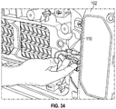
- FIG. 34 illustrates a method of reestablishing an electrical connection between the existing spare tire carrier assembly and the vehicle.
- FIG. 35 illustrates the swing away support assembly attached to the rear panel of the vehicle and supporting the existing spare tire carrier assembly.
- FIGS. 36-37 illustrate a method of attaching a camera cover to a camera housing of the existing spare tire carrier assembly.
- FIG. 38 illustrates a method of securing a tire to the swing away support assembly.
- FIG. 39 is a side view of the swing away support assembly attached to the vehicle and supporting the existing spare tire carrier assembly and the tire.
- a swing away support assembly for a spare tire carrier that can include a backup camera and/or rear light, which has advantages over previously used spare tire carrier assemblies.
- the swing away support assembly can advantageously help support heavy tires and other objects that might otherwise have been mounted directly to the sheet metal of the vehicle, thereby reducing the risk of damage to the tailgate of the vehicle.
- the swing away support assembly can also reposition and reuse existing components, such as an existing spare tire carrier assembly with a tire carrier housing, backup camera, and rear light. Repositioning these components not only helps support heavy loads, but also creates additional clearance for larger objects (e.g., larger tires) to be mounted to the vehicle.
- Reusing existing electronics advantageously avoids creating more waste, is better for the environment than replacing such components, is less expensive, and is an easier, less time-consuming process.
- FIG. 1 illustrates an existing spare tire carrier assembly 200 , known as an original equipment manufacturer (OEM) spare tire carrier, connected to a rear panel 102 of a vehicle 100 .
- the carrier assembly 200 can include a tire carrier housing 202 , a rear camera 206 such as a backup camera, a camera housing 204 , a rear light mount 210 , and a rear light 212 .
- the camera 206 can be protected by a camera cover 208 ( FIG. 10 ).
- the rear light mount 210 can include light mount support posts 214 .
- the tire carrier housing 202 can define channels for receiving the posts 214 of the rear light mount 210 .
- the camera 206 and rear light 212 can be connected to electrical wiring 110 .
- the electrical wiring 110 can extend through a channel in the tire carrier housing 202 and into an opening 104 , such as a grommet, in the rear panel 102 of the vehicle 100 .
- the tire carrier housing 202 can define a radial surface 203 for supporting a hub of a wheel supporting a tire.
- the carrier assembly 200 can be configured to hold a tire using fasteners 220 , such as bolts.
- Cushions 108 can be attached to the rear panel 102 of the vehicle 100 to the lateral sides of the carrier assembly 200 .
- the cushions 108 can form a buffer between a tire mounted on the carrier assembly 200 and the rear panel of the vehicle 100 .
- the carrier assembly 200 can be attached directly to the tailgate or sheet metal of a rear panel 102 of the vehicle 100 .
- FIGS. 2-6 illustrate an embodiment of a swing away support assembly 400 configured to reposition the existing spare tire carrier assembly 200 to provide additional support and reinforcement for heavy objects, such as heavy tires, and to space the existing spare tire carrier assembly 200 away from the rear panel 102 of the vehicle 100 .
- the swing away support assembly 400 can enable the existing spare tire carrier assembly 200 to be positioned in several different configurations and can provide for greater customization. For example, as discussed in detail below, the swing away support assembly 400 can provide different options for the height of the tire carrier housing 202 relative to the bumper or the ground beneath the vehicle 100 , the height of the rear light 212 relative to the tire carrier housing 202 , and the distance between the rear panel 102 of the vehicle 100 and the tire carrier housing 202 .
- the swing away support assembly 400 can be mounted on a vehicle 100 , such as a Jeep.
- the support assembly 400 can be attached to a rear portion of the vehicle 100 , such as to a bumper or rear panel 102 of the vehicle 100 .
- the support assembly 400 can be mounted on top of a hinge reinforcement 114 that is attached to the rear panel 102 of the vehicle (as shown mounted to the vehicle 100 in FIG. 1 ).
- the existing bumper 112 of the vehicle 100 can be replaced with a bumper that is compatible with the support assembly 400 .
- modifications can be made to the existing bumper 112 to make it compatible with the support assembly 400 , such as drilling a mounting hole into the existing bumper 112 .
- the swing away support assembly 400 can be mounted on the vehicle 100 prior to removing the existing spare tire carrier assembly 200 from the rear panel 102 of the vehicle 100 .
- the swing away support assembly 400 can include a main body 402 , a vehicle mount 430 , an arm 450 , and a pivot 460 .
- the swing away support assembly 400 can optionally include an accessory mount 470 .
- the swing away support assembly 400 can be coupled to the vehicle 100 in at least two locations, such as at a first location on the bumper and at a second location on the rear panel 102 of the vehicle 100 (e.g., via the vehicle mount 430 ).
- the pivot 460 can be a rotatable component configured to be attached to the vehicle 100 , such as to a bumper or tailgate of the vehicle 100 .
- the arm 450 can extend between, and connect, the pivot 460 and the main body 402 .
- the main body 402 can include a support platform 404 and a frame 406 .
- the structure of the main body 402 can allow for attachment of the existing spare tire carrier assembly 200 to the swing away support assembly 400 .
- the support platform 404 can include a plurality of holes 412 that correspond with a bolt pattern of the existing spare tire carrier assembly 200 .
- the vehicle mount 430 as shown in FIG. 3 , can be configured to attach to the rear panel 102 of the vehicle 100 and to connect the main body 402 of the swing away support assembly 400 to the vehicle 100 .
- the swing away support assembly 400 allows for the existing spare tire carrier assembly 200 , such as an OEM carrier, to be removed from the sheet metal of the rear panel 102 of the vehicle 100 and attached to the main body 402 of the swing away support assembly 400 , such as to the support platform 404 .
- the carrier assembly 200 including the rear camera 206 and the rear light 212 , can be removed from the vehicle 100 and easily reattached to the main body 402 of the swing away support assembly 400 .
- the carrier assembly 200 can be removed from the vehicle 100 and reattached to the support platform 404 without disassembling or separating the components of the existing spare tire carrier assembly 200 , such as the tire carrier housing 202 , camera housing 204 , rear light mount 210 , camera 206 , and rear light 212 .
- the electrical wiring 110 between the vehicle 100 and the camera 206 and/or between the vehicle 100 and the rear light 212 does not need to be disconnected (e.g., removed, cut, or otherwise disconnected) in order to remove the carrier assembly 200 from the rear panel 102 of the vehicle and reattach it to the swing away support assembly 400 .
- the pivot 460 can be a rotatable component configured to connect with a portion of the vehicle 100 .
- at least a portion of the pivot 460 can be inserted into a corresponding opening in a bumper.
- the pivot 460 can be stepped.
- the pivot 460 can include two or more sections with different diameters.
- the pivot 460 can include a first section 462 , a second section 463 , and a third section 464 .
- the diameter of each section can be smaller than the diameter of the section (if any) above it.
- the diameter of the first section 462 can be smaller than the diameter of the second section 463 , which can be smaller than the diameter of the third section 464 .
- the section of the pivot 460 with the widest diameter can be configured to sit above an upper surface of a bumper and the section(s) with the smaller diameter(s) can be configured to be inserted within the bumper.
- the section(s) of the pivot 460 that are inserted into the bumper can act as an anchor and the section(s) of the pivot 460 disposed above, or flush with, the upper surface of the bumper can be connected to at least one arm 450 .
- the swing away support assembly 400 can include at least one arm 450 .
- the arms 450 can extend from and/or connect the pivot 460 to the main body 402 of the support assembly 400 .
- the arms 450 can connect to the frame 406 .
- the arms 450 and the frame 406 can be made of the same structure and/or material.
- the arms 450 and the frame 406 can merge and/or be integral in a single component.
- the main body 402 of the swing away support assembly 400 can comprise a frame 406 and a support platform 404 .
- the main body 402 can be a single component or an assembly of multiple components.
- the frame 406 can be a tubular structure defining a perimeter of the main body 402 and open in the center as shown.
- the shape of the frame 406 can be generally rectangular, square, or any other shape corresponding to the shape of the support platform 404 .
- the support platform 404 can include apertures 410 to provide access and/or clearance for different purposes, such as to extend electrical wiring or a connector (e.g., a link) through.
- the support platform 404 can include holes 412 for fasteners, such as bolts, to be inserted into.
- the holes 412 can correspond to the bolt pattern of the tire carrier housing 202 .
- At least some of the fasteners 220 that were originally used to attach the existing spare tire carrier assembly 200 to the rear panel 102 of the vehicle 100 can be repurposed or reused to connect components of the swing away support assembly 400 (e.g., to each other, to the existing spare tire carrier assembly 200 , and/or to the vehicle 100 ).
- the support platform 404 can include more than one set of holes 412 which correspond to the bolt pattern of the tire carrier housing 202 .
- the support platform 404 can have two or more sets of holes 412 spaced apart from one another (e.g., vertically or horizontally).
- the different sets of holes 412 can allow the tire carrier housing 202 to be positioned in different locations on the support platform 404 , which may be higher, lower, to the left, or to the right of the original position of the carrier assembly 200 on the rear panel 102 of the vehicle 100 . This can advantageously allow for different sized tires, such as larger tires, to be mounted on the swing away support assembly 400 .
- the support platform 404 can include a link mount 420 that is configured to receive and/or connect to an end of a link.
- the link mount 420 can have an upper segment and a lower segment spaced apart from the upper segment.
- the upper and lower segments can extend outward from a face of the support platform 404 in a direction away from the vehicle 100 (when the support assembly 400 is attached to the vehicle 100 ).
- the upper and lower segments can be disposed above and below an aperture 410 in the support platform 404 , respectively, such that an end of the link can extend through the aperture 410 , between the upper and lower segments of the link mount 420 .
- Each of the segments can define an opening for a fastener or connector to extend through.
- An end of the link can extend between the upper and lower segments of the link mount 420 and be secured by fasteners extending through the openings in the upper and lower segments.
- the support platform 404 can include back light mount supports 408 (as shown in FIG. 5 ) configured to reinforce the light mount support posts 214 of the existing spare tire carrier assembly 200 when the carrier assembly 200 is connected to the support platform 404 .
- the back light mount supports 408 can include multiple sets of openings for bolts to pass through, allowing the rear light mount 210 (and rear light 212 ) to be mounted at different heights relative to the support platform 404 .
- the support platform 404 can be a flat plate.
- the support platform 404 can be connected to the frame 406 , forming the main body 402 .
- the support platform 404 can include outer flanges 416 that extend around at least a portion of the frame 406 .
- the outer flanges 416 can extend from at least three sides of the support platform 404 and around at least a portion of three or more corresponding sides of the frame 406 .
- each outer flange 416 of the support platform 404 can include a plurality of accessory holes 414 .
- the accessory holes 414 can be disposed at an angle relative to the ground beneath the vehicle 100 .
- Various objects, such as a jack for a vehicle can be mounted to the support platform 404 using the accessory holes 414 .
- the swing away support assembly 400 can include an accessory mount 470 .
- the accessory mount 470 can include openings 472 along a front surface of the mount 470 .
- Various objects, such as vehicle accessories, can be mounted to the accessory mount 472 via the openings 472 .
- the vehicle mount 430 of the swing away support assembly 400 can be configured to attach to the rear panel 102 of the vehicle 100 .
- the vehicle mount 430 can include an opening 432 through which a vent panel 106 on the vehicle 100 can extend. In some embodiments, the opening 432 is defined by at least three edges or sides.
- the vehicle mount 430 can include a link mount 440 that is configured to receive and/or connect to an end of a link.
- the link mount 440 can have an upper segment and a lower segment spaced apart from the upper segment. Each of the segments can define an opening for a fastener or connector to extend through. An end of the link can extend between the upper and lower segments of the link mount 440 and be secured by fasteners extending through the openings in the upper and lower segments.
- FIGS. 7-8 illustrate an embodiment of a support assembly 700 .
- the support assembly 700 can have the same or similar features and/or functions as the swing away support assembly 400 , except as otherwise described.
- the support assembly 700 can secure a tire 600 at an angle relative to a vertical plane. This can advantageously accommodate larger tires as the angled tire can be oriented such that it does not come into contact with any other vehicle components.
- the rear light can be positioned at least partially below the support assembly 700 .
- FIG. 9 illustrates another embodiment of a swing away support assembly 400 ′ attached to the vehicle 100 and supporting the attached existing spare tire carrier assembly 200 and tire 600 .
- the support assembly 400 ′ can have the same or similar features and/or functions as the swing away support assembly 400 , except as otherwise described. As shown, when the swing away support assembly 400 ′ is mounted on the vehicle 100 and the tire 600 is attached, at least a portion of the rear light 212 is positioned above the tire 600 .
- the swing away support assembly 400 ′ can advantageously position large tires such that there is sufficient clearance for large tires, while also maintaining visibility of the rear light 212 , which provides road safety benefits.
- FIGS. 10-39 illustrate embodiments of a method of installing the swing away support assembly 400 ′.
- the existing spare tire carrier assembly 200 can be attached to the rear panel 102 of the vehicle 100 .
- the hinge reinforcement 114 can optionally be attached to the rear panel 102 .
- the swing away support assembly 400 ′ can be mounted to the bumper 300 .
- the bumper 300 can have a pivot mount 310 , such as a hole in the bumper 300 that is configured to receive at least a portion of the pivot 460 of the support assembly 400 ′.
- the pivot mount 310 can be located towards a lateral end of the bumper 300 , in a location more lateral than the hinges of the vehicle's tailgate when the bumper 300 is mounted on the vehicle 100 . As shown, at least a portion (e.g., a section) of the pivot 460 can be inserted into the pivot mount 310 on the bumper 300 . If the existing bumper on the vehicle is not already compatible with the support assembly 400 ′, the existing bumper can be replaced with the bumper 300 or modified to accommodate the pivot 460 of the support assembly 400 ′ (e.g., by forming a corresponding opening in the bumper). As shown, the pivot 460 can be connected to the bumper 300 prior to removing the existing spare tire carrier assembly 200 from the rear panel 102 .
- the support assembly 400 can be connected to the bumper 300 such that the support assembly 400 is initially spaced away from (e.g., swung open relative to) the carrier assembly 200 that is mounted on the rear panel 102 of the vehicle 100 .
- the carrier assembly 200 is removed from the rear panel 102 of the vehicle 100 so that it can be mounted on the support assembly 400 ′.
- the carrier assembly 200 can be removed as a single unit.
- the tire carrier housing 202 , rear light mount 210 , rear camera 206 , and rear light 212 can remain connected as a single unit when the carrier assembly 200 is removed from the rear panel 102 of the vehicle 100 .
- the electrical wiring 110 from the vehicle 100 can remain connected to the carrier assembly 200 when the carrier assembly 200 is removed from the rear panel 102 of the vehicle.
- the electrical wiring 110 connecting the rear camera 206 to the vehicle 100 and/or the electrical wiring 110 connecting the rear light 212 to the vehicle 100 can remain connected when the carrier assembly 200 is removed from the rear panel 102 .
- a cover on the back of the vehicle tailgate can be removed and the electrical wiring 110 between the vehicle 100 and the rear camera 206 and/or the vehicle 100 and the rear light 212 can be disconnected.
- At least one vent panel 106 on the rear panel 102 of the vehicle 100 can be removed, as illustrated in FIG. 19 . This can allow for a tighter seal and/or closer fit between the vehicle mount 430 and the rear panel 102 of the vehicle.
- the vehicle mount 430 can be attached to the rear panel 102 of the vehicle 100 .
- a portion of the vehicle mount 430 contacts a portion of the optional hinge reinforcement 114 when the vehicle mount 430 is connected to the rear panel 102 .
- the vehicle mount 430 can be positioned such that the opening 432 in the vehicle mount 430 provides an opening for at least one of the vent panels 106 to extend through.
- the vehicle mount 430 is connected to the rear panel 102 using at least some of the fasteners 220 that had previously connected the existing spare tire carrier assembly 200 to the rear panel 102 of the vehicle 100 .
- FIGS. 21-24 illustrate a method of mounting the existing spare tire carrier assembly 200 on to the swing away support assembly 400 ′.
- the carrier assembly 200 can be attached to the support assembly 400 ′ in a single step.
- the carrier assembly 200 can be mounted on to the support assembly 400 ′ as a single unit (e.g., with the tire carrier housing 202 , rear light mount 210 , rear camera 206 , and rear light 212 still assembled together).
- the electrical wiring 110 can extend between the carrier assembly 200 and the vehicle 100 through the aperture(s) 410 in the support platform 404 of the support assembly 400 ′, as illustrated in FIGS. 21 and 24 .
- a stop 490 can be mounted on the back of the main body 402 of the support assembly 400 ′, as shown in FIG. 24 .
- the stop 490 can be made of rubber or another soft material configured to reduce friction.
- the stop 490 can reduce the amount of friction and/or wear experienced by the tailgate and/or rear panel 102 of the vehicle 100 as a result of the tailgate door being swung open and closed in use.
- the cushion(s) 108 that are mounted on the rear panel 102 of the vehicle 100 can be removed from the rear panel 102 and reattached to the support platform 404 of the swing away support assembly 400 ′, as illustrated in FIGS. 27-28 .
- This can advantageously create a buffer between the support platform 404 and a tire that is loaded onto the carrier assembly 200 , reducing the risk of damage to the support assembly 400 ′.
- a link 480 can be used to connect the vehicle mount 430 to the main body 402 of the swing away support assembly 400 ′ while maintaining a gap 500 between the vehicle mount 430 and/or the rear panel 102 of the vehicle 100 and the main body 402 .
- the link 480 can have a first end 482 and a second end 484 opposite the first end 482 .
- the link 480 can be about 4-8 inches long.
- the link 480 can be at least about 5 inches long.
- Each end 482 , 484 of the link 480 can include a rotatable connector 486 , such as a rotatable eyelet connector.
- the first end 482 of the link 480 can couple to a first link mount 440 of the vehicle mount 430 (as shown in FIG. 29 ) and the second end 484 of the link 480 can couple to a second link mount 420 of the support platform 404 (as shown in FIG. 30 ).
- This can advantageously allow the vehicle tailgate and the support assembly 400 ′ to swing together as a single unit (as shown in FIG. 33 ) when the tailgate is swung open and closed while maintaining the gap 500 between the vehicle mount 430 and/or the rear panel 102 of the vehicle 100 and the main body 402 of the support assembly 400 ′ (as shown in FIG. 32 ).
- the size of the gap 500 is adjustable based on the length of the link 480 .
- FIGS. 33-34 illustrate a method of reestablishing the electrical connection between the vehicle 100 and the rear camera 206 and/or the rear light 212 in the event that the rear camera 206 and/or the rear light 212 were disconnected from the vehicle 100 during the installation of the swing away support assembly 400 ′.
- the inner panel of the tailgate can be removed to provide access to the electrical wiring 110 and the vehicle connectors can be coupled to the corresponding rear camera 206 and/or rear light 212 connectors.
- FIGS. 35-39 illustrate a method of securing a tire 600 to the carrier assembly 200 that is mounted on the support assembly 400 ′ attached to the vehicle 100 .
- the camera cover 208 is decoupled from the camera housing 204 before loading the tire 600 on to the carrier assembly 200 .
- the camera cover 208 can be reattached to the camera housing 204 when the tire 600 is mounted on the vehicle 100 .
- the tire 600 is secured in place using fasteners, such as bolts (as shown in FIG. 38 ).
- the above recited ranges can be specific ranges, and not within a particular % of the value. For example, within less than or equal to 10 wt./vol. % of, within less than or equal to 5 wt./vol. % of, within less than or equal to 1 wt./vol. % of, within less than or equal to 0.1 wt./vol. % of, and within less than or equal to 0.01 wt./vol. % of the stated amount.
Landscapes
- Engineering & Computer Science (AREA)
- Mechanical Engineering (AREA)
- Chemical & Material Sciences (AREA)
- Combustion & Propulsion (AREA)
- Transportation (AREA)
- Body Structure For Vehicles (AREA)
Abstract
Description
Claims (23)
Priority Applications (1)
| Application Number | Priority Date | Filing Date | Title |
|---|---|---|---|
| US16/395,000 US10858050B2 (en) | 2018-04-25 | 2019-04-25 | Swing away support assembly for spare tire carrier |
Applications Claiming Priority (2)
| Application Number | Priority Date | Filing Date | Title |
|---|---|---|---|
| US201862662635P | 2018-04-25 | 2018-04-25 | |
| US16/395,000 US10858050B2 (en) | 2018-04-25 | 2019-04-25 | Swing away support assembly for spare tire carrier |
Publications (2)
| Publication Number | Publication Date |
|---|---|
| US20190351955A1 US20190351955A1 (en) | 2019-11-21 |
| US10858050B2 true US10858050B2 (en) | 2020-12-08 |
Family
ID=68534168
Family Applications (1)
| Application Number | Title | Priority Date | Filing Date |
|---|---|---|---|
| US16/395,000 Active 2039-04-27 US10858050B2 (en) | 2018-04-25 | 2019-04-25 | Swing away support assembly for spare tire carrier |
Country Status (1)
| Country | Link |
|---|---|
| US (1) | US10858050B2 (en) |
Cited By (8)
| Publication number | Priority date | Publication date | Assignee | Title |
|---|---|---|---|---|
| US11136077B2 (en) | 2016-10-27 | 2021-10-05 | Lund Motion Products, Inc. | Adjustable spare tire carrier |
| US20230150587A1 (en) * | 2021-11-12 | 2023-05-18 | Boomerang Enterprises, Inc. | Systems and Methods for Offset Wheel Spare Tire Covers and Accessories |
| US11794659B1 (en) | 2022-06-23 | 2023-10-24 | Royce Sullivan | Modular spare tire accessory mounting system |
| USD1015244S1 (en) * | 2021-12-03 | 2024-02-20 | Hangzhou Jiye Technology Co., Ltd. | Spare tire rack |
| US20240140323A1 (en) * | 2022-11-02 | 2024-05-02 | Glen Heacock | Tire Mounted Accessory System |
| US12233956B2 (en) | 2021-05-06 | 2025-02-25 | Leer Group | Tire carrier and bedslide attachment systems |
| US12441416B2 (en) | 2023-05-30 | 2025-10-14 | Fca Us Llc | Body mounted spare tire tailgate |
| US12448056B2 (en) | 2022-02-07 | 2025-10-21 | Leer Group | Bedslide assembly |
Families Citing this family (3)
| Publication number | Priority date | Publication date | Assignee | Title |
|---|---|---|---|---|
| US10858050B2 (en) * | 2018-04-25 | 2020-12-08 | Lund Motion Products, Inc. | Swing away support assembly for spare tire carrier |
| CN112706845A (en) * | 2021-01-04 | 2021-04-27 | 北京汽车集团越野车有限公司 | Vehicle spare tire support assembly and vehicle |
| USD1068599S1 (en) * | 2022-07-31 | 2025-04-01 | Landon Cole McMath | Vehicle tire carrier |
Citations (21)
| Publication number | Priority date | Publication date | Assignee | Title |
|---|---|---|---|---|
| US2805807A (en) | 1954-01-13 | 1957-09-10 | Chrysler Corp | Continental spare tire mounting |
| US4140255A (en) | 1977-06-24 | 1979-02-20 | Blackstone Mfg. Co., Inc. | Spare wheel carrier for vehicles |
| DE2946449A1 (en) | 1979-11-17 | 1981-05-27 | Jost-Werke Gmbh, 6000 Frankfurt | Spare wheel supporting bracket - has right-angled triangle shape allowing wheel fixing in three alternative positions |
| US4561575A (en) | 1984-01-04 | 1985-12-31 | Jones Robert R | Swing away tire carrier and hitch |
| US4718582A (en) * | 1987-02-24 | 1988-01-12 | Iovenitti Thomas A | Spare tire mounting bracket for van-type vehicle |
| US4817834A (en) * | 1985-09-20 | 1989-04-04 | Weiler Raywood C | Bumper mounted spare wheel carrier |
| US5104015A (en) | 1990-06-01 | 1992-04-14 | Johnson Bruce D | Sport vehicle rack and method therefor |
| US5370285A (en) | 1993-12-16 | 1994-12-06 | Steelman; Michael E. | Quick release spare tire rack |
| US5806736A (en) * | 1996-04-23 | 1998-09-15 | Kincart; Mark S. | Exterior dual cargo carrier |
| US6659318B2 (en) | 2000-10-10 | 2003-12-09 | Anthony J. Newbill | Spare wheel carrier |
| US6796466B2 (en) | 2000-10-27 | 2004-09-28 | Bestop, Inc. | Spare tire carrier for a vehicle |
| US6923351B2 (en) * | 2002-10-24 | 2005-08-02 | Sma-Patents, L.L.C. | Tire carrier assembly |
| US7021685B2 (en) * | 2004-07-12 | 2006-04-04 | Newbill Anthony J | Automotive bumper construction |
| US7861902B2 (en) | 2005-08-17 | 2011-01-04 | Chrysler Group Llc | Spare tire stowage apparatus |
| US8251265B2 (en) | 2011-01-12 | 2012-08-28 | Grudek Michael A | Spare tire carrier for all-terrain vehicles |
| US8540125B2 (en) * | 2004-02-23 | 2013-09-24 | Anthony J. Newbill | Spare tire carrier assembly |
| US20180118283A1 (en) | 2016-10-27 | 2018-05-03 | Lund Motion Products, Inc. | Adjustable spare tire carrier |
| US20190126840A1 (en) * | 2017-11-01 | 2019-05-02 | Wheel Group Holdings, LLC | Bumper-carrier assembly for vehicle |
| US10370044B2 (en) * | 2017-09-29 | 2019-08-06 | Ford Global Technologies, Llc | Tire carriers for vehicles and related methods |
| US20190351955A1 (en) * | 2018-04-25 | 2019-11-21 | Lund Motion Products, Inc. | Swing away support assembly for spare tire carrier |
| US10661845B2 (en) * | 2017-10-27 | 2020-05-26 | Naade, Inc. | Spare tire mount for motor vehicle |
-
2019
- 2019-04-25 US US16/395,000 patent/US10858050B2/en active Active
Patent Citations (21)
| Publication number | Priority date | Publication date | Assignee | Title |
|---|---|---|---|---|
| US2805807A (en) | 1954-01-13 | 1957-09-10 | Chrysler Corp | Continental spare tire mounting |
| US4140255A (en) | 1977-06-24 | 1979-02-20 | Blackstone Mfg. Co., Inc. | Spare wheel carrier for vehicles |
| DE2946449A1 (en) | 1979-11-17 | 1981-05-27 | Jost-Werke Gmbh, 6000 Frankfurt | Spare wheel supporting bracket - has right-angled triangle shape allowing wheel fixing in three alternative positions |
| US4561575A (en) | 1984-01-04 | 1985-12-31 | Jones Robert R | Swing away tire carrier and hitch |
| US4817834A (en) * | 1985-09-20 | 1989-04-04 | Weiler Raywood C | Bumper mounted spare wheel carrier |
| US4718582A (en) * | 1987-02-24 | 1988-01-12 | Iovenitti Thomas A | Spare tire mounting bracket for van-type vehicle |
| US5104015A (en) | 1990-06-01 | 1992-04-14 | Johnson Bruce D | Sport vehicle rack and method therefor |
| US5370285A (en) | 1993-12-16 | 1994-12-06 | Steelman; Michael E. | Quick release spare tire rack |
| US5806736A (en) * | 1996-04-23 | 1998-09-15 | Kincart; Mark S. | Exterior dual cargo carrier |
| US6659318B2 (en) | 2000-10-10 | 2003-12-09 | Anthony J. Newbill | Spare wheel carrier |
| US6796466B2 (en) | 2000-10-27 | 2004-09-28 | Bestop, Inc. | Spare tire carrier for a vehicle |
| US6923351B2 (en) * | 2002-10-24 | 2005-08-02 | Sma-Patents, L.L.C. | Tire carrier assembly |
| US8540125B2 (en) * | 2004-02-23 | 2013-09-24 | Anthony J. Newbill | Spare tire carrier assembly |
| US7021685B2 (en) * | 2004-07-12 | 2006-04-04 | Newbill Anthony J | Automotive bumper construction |
| US7861902B2 (en) | 2005-08-17 | 2011-01-04 | Chrysler Group Llc | Spare tire stowage apparatus |
| US8251265B2 (en) | 2011-01-12 | 2012-08-28 | Grudek Michael A | Spare tire carrier for all-terrain vehicles |
| US20180118283A1 (en) | 2016-10-27 | 2018-05-03 | Lund Motion Products, Inc. | Adjustable spare tire carrier |
| US10370044B2 (en) * | 2017-09-29 | 2019-08-06 | Ford Global Technologies, Llc | Tire carriers for vehicles and related methods |
| US10661845B2 (en) * | 2017-10-27 | 2020-05-26 | Naade, Inc. | Spare tire mount for motor vehicle |
| US20190126840A1 (en) * | 2017-11-01 | 2019-05-02 | Wheel Group Holdings, LLC | Bumper-carrier assembly for vehicle |
| US20190351955A1 (en) * | 2018-04-25 | 2019-11-21 | Lund Motion Products, Inc. | Swing away support assembly for spare tire carrier |
Cited By (10)
| Publication number | Priority date | Publication date | Assignee | Title |
|---|---|---|---|---|
| US11136077B2 (en) | 2016-10-27 | 2021-10-05 | Lund Motion Products, Inc. | Adjustable spare tire carrier |
| US11760429B2 (en) | 2016-10-27 | 2023-09-19 | Lund Motion Products, Inc. | Adjustable spare tire carrier |
| US12233956B2 (en) | 2021-05-06 | 2025-02-25 | Leer Group | Tire carrier and bedslide attachment systems |
| US20230150587A1 (en) * | 2021-11-12 | 2023-05-18 | Boomerang Enterprises, Inc. | Systems and Methods for Offset Wheel Spare Tire Covers and Accessories |
| US12344325B2 (en) * | 2021-11-12 | 2025-07-01 | Boomerang Enterprises, Inc. | Systems and methods for offset wheel spare tire covers and accessories |
| USD1015244S1 (en) * | 2021-12-03 | 2024-02-20 | Hangzhou Jiye Technology Co., Ltd. | Spare tire rack |
| US12448056B2 (en) | 2022-02-07 | 2025-10-21 | Leer Group | Bedslide assembly |
| US11794659B1 (en) | 2022-06-23 | 2023-10-24 | Royce Sullivan | Modular spare tire accessory mounting system |
| US20240140323A1 (en) * | 2022-11-02 | 2024-05-02 | Glen Heacock | Tire Mounted Accessory System |
| US12441416B2 (en) | 2023-05-30 | 2025-10-14 | Fca Us Llc | Body mounted spare tire tailgate |
Also Published As
| Publication number | Publication date |
|---|---|
| US20190351955A1 (en) | 2019-11-21 |
Similar Documents
| Publication | Publication Date | Title |
|---|---|---|
| US10858050B2 (en) | Swing away support assembly for spare tire carrier | |
| AU2010354770B2 (en) | Improved vehicle bumper | |
| US9321495B2 (en) | Method of assembling a front end assembly of a vehicle | |
| CA2564348C (en) | One piece running board bracket | |
| US7806452B2 (en) | Adjustable security partition for a vehicle | |
| CA2626374C (en) | Removable chassis skirt | |
| US20110006553A1 (en) | Winch Carrier and Grille Guard Mounting System | |
| US6270051B1 (en) | Drive train mount adapter plate and pivot bracket | |
| US8342549B1 (en) | Running board for three wheel motorcycles | |
| CN212125302U (en) | Motor vehicle | |
| US20080310179A1 (en) | Hinged Light Bar | |
| US20080310668A1 (en) | Speaker retention bracket and method | |
| US20200269789A1 (en) | Side Underride Guard | |
| US20230365060A1 (en) | Vehicle body structure mounted side view mirror | |
| US10676010B2 (en) | Outer guard for transport refrigeration systems | |
| US20150283951A1 (en) | Carrying System for Jeep Doors and Hardtop | |
| US20250229618A1 (en) | Bracket assembly for attaching component to vehicle | |
| CN112310903A (en) | Bushing and method for supporting electrical wiring through a hole and aircraft comprising such a bushing | |
| CA3077532C (en) | Frame extension for vehicle | |
| US9783398B1 (en) | Hoist system for ATVS and ATV with hoist system | |
| US20250282298A1 (en) | Vehicle equipment mount | |
| US7185746B2 (en) | Damper-mounting structure | |
| CN203438943U (en) | Connecting device for rear placing table | |
| JPH03284433A (en) | Front car body construction and method of assembling car body of automobile | |
| US11673517B2 (en) | Wiring harness connector cover assembly for a vehicle |
Legal Events
| Date | Code | Title | Description |
|---|---|---|---|
| FEPP | Fee payment procedure |
Free format text: ENTITY STATUS SET TO UNDISCOUNTED (ORIGINAL EVENT CODE: BIG.); ENTITY STATUS OF PATENT OWNER: LARGE ENTITY |
|
| STPP | Information on status: patent application and granting procedure in general |
Free format text: DOCKETED NEW CASE - READY FOR EXAMINATION |
|
| AS | Assignment |
Owner name: LUND MOTION PRODUCTS, INC., GEORGIA Free format text: ASSIGNMENT OF ASSIGNORS INTEREST;ASSIGNOR:HEADLEE, JAKE;REEL/FRAME:051585/0589 Effective date: 20191110 |
|
| STPP | Information on status: patent application and granting procedure in general |
Free format text: PUBLICATIONS -- ISSUE FEE PAYMENT VERIFIED |
|
| STCF | Information on status: patent grant |
Free format text: PATENTED CASE |
|
| AS | Assignment |
Owner name: BANK OF AMERICA, N.A., AS COLLATERAL AGENT, TEXAS Free format text: PATENT SECURITY AGREEMENT (ABL);ASSIGNOR:LUND MOTION PRODUCTS, INC.;REEL/FRAME:055175/0901 Effective date: 20210129 Owner name: JEFFERIES FINANCE LLC, AS COLLATERAL AGENT, NEW YORK Free format text: PATENT SECURITY AGREEMENT (TL);ASSIGNOR:LUND MOTION PRODUCTS, INC.;REEL/FRAME:055174/0699 Effective date: 20210129 |
|
| FEPP | Fee payment procedure |
Free format text: MAINTENANCE FEE REMINDER MAILED (ORIGINAL EVENT CODE: REM.); ENTITY STATUS OF PATENT OWNER: LARGE ENTITY |
|
| FEPP | Fee payment procedure |
Free format text: SURCHARGE FOR LATE PAYMENT, LARGE ENTITY (ORIGINAL EVENT CODE: M1554); ENTITY STATUS OF PATENT OWNER: LARGE ENTITY |
|
| MAFP | Maintenance fee payment |
Free format text: PAYMENT OF MAINTENANCE FEE, 4TH YEAR, LARGE ENTITY (ORIGINAL EVENT CODE: M1551); ENTITY STATUS OF PATENT OWNER: LARGE ENTITY Year of fee payment: 4 |