US10857669B2 - Modular angular-momentum driven magnetically connected robots - Google Patents
Modular angular-momentum driven magnetically connected robots Download PDFInfo
- Publication number
- US10857669B2 US10857669B2 US14/067,132 US201314067132A US10857669B2 US 10857669 B2 US10857669 B2 US 10857669B2 US 201314067132 A US201314067132 A US 201314067132A US 10857669 B2 US10857669 B2 US 10857669B2
- Authority
- US
- United States
- Prior art keywords
- movement
- modules
- magnets
- frame
- frame structure
- Prior art date
- Legal status (The legal status is an assumption and is not a legal conclusion. Google has not performed a legal analysis and makes no representation as to the accuracy of the status listed.)
- Active, expires
Links
Images


Classifications
-
- B—PERFORMING OPERATIONS; TRANSPORTING
- B25—HAND TOOLS; PORTABLE POWER-DRIVEN TOOLS; MANIPULATORS
- B25J—MANIPULATORS; CHAMBERS PROVIDED WITH MANIPULATION DEVICES
- B25J9/00—Program-controlled manipulators
- B25J9/08—Program-controlled manipulators characterised by modular constructions
-
- A—HUMAN NECESSITIES
- A63—SPORTS; GAMES; AMUSEMENTS
- A63H—TOYS, e.g. TOPS, DOLLS, HOOPS OR BUILDING BLOCKS
- A63H29/00—Drive mechanisms for toys in general
- A63H29/20—Flywheel driving mechanisms
-
- A—HUMAN NECESSITIES
- A63—SPORTS; GAMES; AMUSEMENTS
- A63H—TOYS, e.g. TOPS, DOLLS, HOOPS OR BUILDING BLOCKS
- A63H33/00—Other toys
- A63H33/04—Building blocks, strips, or similar building parts
- A63H33/046—Building blocks, strips, or similar building parts comprising magnetic interaction means, e.g. holding together by magnetic attraction
-
- A—HUMAN NECESSITIES
- A63—SPORTS; GAMES; AMUSEMENTS
- A63H—TOYS, e.g. TOPS, DOLLS, HOOPS OR BUILDING BLOCKS
- A63H33/00—Other toys
- A63H33/26—Magnetic or electric toys
-
- Y—GENERAL TAGGING OF NEW TECHNOLOGICAL DEVELOPMENTS; GENERAL TAGGING OF CROSS-SECTIONAL TECHNOLOGIES SPANNING OVER SEVERAL SECTIONS OF THE IPC; TECHNICAL SUBJECTS COVERED BY FORMER USPC CROSS-REFERENCE ART COLLECTIONS [XRACs] AND DIGESTS
- Y10—TECHNICAL SUBJECTS COVERED BY FORMER USPC
- Y10T—TECHNICAL SUBJECTS COVERED BY FORMER US CLASSIFICATION
- Y10T74/00—Machine element or mechanism
- Y10T74/20—Control lever and linkage systems
- Y10T74/20207—Multiple controlling elements for single controlled element
- Y10T74/20305—Robotic arm
Definitions
- the invention is related to the field of modular robots, and in particular to modular angular-momentum driven magnetically connected robots.
- the prior art includes self-reconfiguring lattice-based modular robots that can be broadly categorized by two attributes: the mode of locomotion and the connection mechanism. Perhaps the most elegant model for locomotion is termed the sliding cube model. In this model, cubes translate (i.e. slide) from one lattice position to another. Despite its theoretical simplicity, no hardware implements this approach in the general 3D case. There are two systems, which implement a 2D version of the sliding cube model in the vertical plane and two systems that operate horizontally. Not only are all of these systems mechanically complex, it is not clear how any of these systems could be extended to 3D.
- a self-configuring robot includes a frame structure that includes a plurality of cylindrical bonding magnets positioned along the edges of the frame structure, the frame structure includes magnetic, non-gendered, hinges on any of the edges of the frame, the hinges provide enough force to maintain a pivot axis through various motions, the cylindrical bonding magnets are free to rotate.
- a movement generator is positioned within the frame structure that applies a torque about the pivot axis to generate multi-axis movement allowing independent locomotion.
- a self-configuring robot includes a frame structure having a plurality of cylindrical bonding magnets positioned along the edges of the frame structure.
- the frame structure includes magnetic, non-gendered, hinges on any of the edges of the frame. The hinges provide enough force to maintain a pivot axis through various motions.
- the cylindrical bonding magnets are free to rotate allowing for multiple self-configurations with another modular structure having magnetic properties.
- An actuator is positioned within the frame structure that includes a belt and a flywheel structure where the actuator is used to tighten the belt that rapidly decelerates the flywheel to create an impulse of torque generating multi-axis movement allowing both robust self-reconfiguration with the other modular structure and independent locomotion.
- the modular robotic system includes a plurality of self-configuring robots.
- Each self-configuring robot includes a frame structure having a plurality of cylindrical bonding magnets positioned along the edges of the frame structure.
- the frame structure includes magnetic, non-gendered, hinges on any of the edges of the frame. The hinges provide enough force to maintain a pivot axis through various motions.
- the cylindrical bonding magnets are free to rotate allowing for multiple self-configurations with other like self-configuring robots.
- a movement generator is positioned within the frame structure that pivots to generate multi-axis movement allowing both robust self-reconfiguration with the other self-configuring robots and independent locomotion.
- FIG. 1A-1C are schematic diagrams illustrating the various embodiments of the inventive M-Block system used in accordance with the invention.
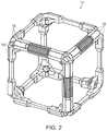
- FIG. 2 is a schematic diagram illustrating the cubic frame used by the M-Block system
- FIG. 3 is a schematic diagram illustrating the magnetic bonding used in accordance with the invention.
- FIGS. 4A-4B are schematic diagrams illustrating the details of the actuator system used in accordance with the invention.
- FIGS. 5A-5C are schematic diagrams illustrating the motions performed by an M-Block module
- FIG. 6 is a schematic diagram illustrating the details of calculating the physical interactions of an M-Block module
- FIGS. 7A-7E are schematic diagrams illustrating selective lattice configurations formed in accordance with the invention.
- FIG. 8 is a table illustrating experimental results for controlled tests of various motion primitives
- FIGS. 9A-9C are schematic diagrams illustrating groups of M-Block modules moving as rigid assemblies
- FIG. 10 is a graph illustrating the angular velocity profile of the inertial actuator's flywheel as measured by an optical encoder.
- FIG. 11A-11C are graphs illustrating the pull strength of various conditions of the magnetic hinges as measured with a custom-built testing fixture.
- the inventions involves a novel self-assembling, self-reconfiguring cubic robot that uses pivoting actuation to change its intended geometry.
- Each individual module can pivot to move linearly on a substrate of stationary modules.
- the modules can use the same operation to perform convex and concave transitions to change planes.
- Each module can also move independently to traverse planar unstructured environments.
- the modules achieve these movements by quickly transferring angular moment accumulated in a flywheel to the body of the cube.
- the system provides a simplified realization of the modular actions required by the sliding cube model using pivoting.
- the invention is most closely related to existing systems whose modules pivot about the edges they share with their neighbors. These existing pivoting systems are confined to the horizontal plane and use complex connection mechanisms and/or external actuation mechanisms to achieve reconfiguration. These prior works make no attempt to define a generalized, three-dimensional model for reconfiguration through pivoting.
- the invention presents a physical pivoting cube model that can be applied to both solitary modules and groups acting in synchrony by capturing physical quantities including mass, inertia, and bonding forces.
- the other defining characteristic of any modular robotic system is its connectors.
- Many modular systems use mechanical latches to connect neighboring modules. Mechanical latches typically suffer from mechanical complexity and an inability to handle misalignment.
- Other systems such as the Catoms, Molecule, and E-MCube use electromagnets for inter-module connections. Electromagnets consume more power and are not as strong as mechanical latches. Electro-permanent magnets are an attractive alternative because they only consume power when changing state, but they still require high instantaneous currents to actuate and are not readily available.
- One unique system uses fluid forces to join neighboring modules, but must operate while submerged in viscous fluid.
- Another, the Catoms uses electrostatic forces for bonding. The unifying feature of all of these connection mechanisms is that their holding force can be controlled: on, off, or somewhere in-between. This adds complexity and decreases robustness.
- the invention uses a simple mode of location (pivoting), a simple inertial actuator (a flywheel and brake), and a simple bonding mechanism (permanent magnets).
- Actuation through inertial control has been used extensively in space and underwater robotics as well as several earth-bound applications.
- the simplicity of the M-Blocks, with their self-contained inertial actuators, allows the invention to achieve both robust self-reconfiguration and independent locomotion in 3D environments.
- an M-Block 12 is constructed from a 50 mm cubic frame 4 milled from a single piece of 7075 aluminum and the module has a moment of inertial of 63 ⁇ 10 ⁇ 6 kg m2. However, other firm materials, such as plastic or the like can be used as well.
- This frame 4 holds twenty-four cylindrical bonding magnets 5 along its twelve edges.
- Bolt-on panels 6 are attached to the six faces. These panels 6 contain various electrical and mechanical elements such as the inertial actuator 3 and the control PCB 8 . Additionally, each of these panels 6 is inset with eight outward-facing magnets 7 that assist in alignment between neighbors.
- FIG. 1A shows an exemplary embodiment of the M-Block system having an inertial motor controller ( 10 ) and batteries ( 9 ).
- the inertial actuator 3 is composed of a brushless DC motor ( 2 ) which spins a flywheel ( 1 ). Other motors can also be used as well.
- An actuator ( 3 ) is used to tighten a belt which rapidly decelerates the flywheel ( 1 ) to create an impulse of torque.
- the components of the M-Block can move on a structure formed by the passive modules (which still have all necessary magnets) or completely independently over open ground.
- FIGS. 1B-1C show one of several possible ways to extend the actuation system beyond one plane while using a single inertial actuator.
- FIG. 1B allows for motion in all three planes with only a single rotating joint. These three planes are enabled by rotating the actuator unit 11 along an axis 12 that connects to two opposite corners of the robot frame by way of ball bearing 15 .
- This axis 12 creates an angle of 35.26 degrees between the axis and the three adjacent faces.
- the rotating axis 14 of the flywheel 13 is angled roughly 55 degrees from the rotation axis 12 of the unit, so that the plane of the actuator 11 matches up with the faces of the cube, and therefore the X Y and Z planes.
- FIG. 1C shows another orientation of the structure shown in FIG. 1B .
- An important aspect of the M-Block system is the novel design that allows the modules to quickly form magnetic, non-gendered, hinges on any of the cubes' twelve edges. These hinges must provide enough force to maintain a pivot axis through various motions.
- the invention solves this challenge by using twenty-four diametrically polarized cylindrical magnets 16 , two of which are situated coaxially with each edge 18 of the frame 17 , as shown in FIG. 2 .
- the diametrically magnetized cylinder magnets 16 are free to rotate. This rotation allows configurations with two, three, or four modules to form high strength magnetic bonds while allowing the hinges to be achedered.
- Magnets 22 are set back from the corners of each cube by a selective distance, in this case 1 mm, as shown in FIG. 3 .
- This set-back is critical to the M-Block system performance because it guarantees that the strength of a hinge bond between two modules (involving four total magnets) is not dwarfed by the strength of the face bond between two modules (involving sixteen total magnets) when the modules are flush and well aligned.
- the face bonds were much stronger than the hinge bonds, the energy provided by the inertial actuators to break the face-to-face bond would overpower the hinge bond and result in the active module careening away from the assembly.
- edge magnets 22 form strong hinges and serve to connect neighboring modules in the lattice, they are not sufficient to overcome misalignments that are introduced when modules pivot.
- eight diameter disc magnets 24 of a selective size, in this case 2.5 mm, are embedded in each of the six faces. These disc magnets are arranged in an eight-way symmetric pattern in order to maintain the modules' gender neutrality. These alignment magnets 24 are strong enough to pull a module into alignment as it finishes a rotation, but they do not add significant holding force to the face bonds.
- the flywheel itself is a 20 g stainless steel ring with a moment of inertia of 5:5 ⁇ 10 ⁇ 6 kg m2, but other flywheel structures can be used as well. It is rigidly fixed to an out-runner style brushless DC motor. In this case, the brushless DC motor can be capable of spinning at up to 20000 rpm or more.
- a flywheel 45 as shown in FIG. 4A is quickly decelerated with a self-tightening rubber belt 43 that is wrapped around the flywheel's 45 circumference.
- the belt 43 When un-actuated, the belt 43 is loose and constrained by a cage to maintain a spacing, in this case 1 mm, from the flywheel 45 .
- a servo motor 44 is used which pulls the belt 43 in the direction of rotation, as shown in FIG. 4B . As the belt 43 contacts the flywheel 45 , the flywheel's motion further tightens the belt 43 resulting in a rapid deceleration.
- the Inertial Actuator frame 41 is rigid structure which connects various components of the inertial actuator 30 and also maintains a consistent separation between the belt 43 and the flywheel 45 .
- the belt attachment point 42 is a rigid attachment between the actuator frame 41 and the brake belt 43 , and the electrical connection 46 are wires which actuate the motor 44 are brought to the central controller unit.
- the belt actuator attachment point 47 is a joint where the belt actuator output 48 attaches to the belt 43 .
- Each module is controlled by a custom-designed PCB, in this case a 32-bit ARM microprocessor and an 802.11.4 XBee radio from Digi International. Three 125 mAh LiPo batteries connected in series can power the modules, but other types of batteries can be used as well.
- the processor responds to commands received wirelessly the user's computer in order to control the inertial actuator.
- the low-level BLDC control can be performed by a commercial motor driver or the like.
- each PCB can include a 6-axis IMU (to determine absolute orientation); an outwardfacing IR LED/photodiode pair (for neighbor-to-neighbor communication); and several Hall Effect sensors to detect misalignment between modules.
- the sliding cube model is one of the more prevalent algorithmic frameworks that has been developed for modeling the motions of lattice based self-reconfiguring modular robots.
- SCM sliding cube model
- PCM physical pivoting cube model
- the inventive model includes several additional assumptions about the types of motions the modules can execute and implement. While already assumed by other models, the modules 52 involved in pivoting motions sweep out a volume that must not intersect other modules, as shown in FIG. 5A . Stable lattice configurations must have modules connected via their faces, not their edges 54 , as shown in FIG. 5B . Modules 56 involved in pivoting motions must be able to slide past stationary modules in adjacent planes, as shown in FIG. 5C . This allows modules to move independently. Modules can locomote in unstructured environments without a supporting lattice, (e.g. on the ground). Multiple modules can move as a connected unit, but they must all share a single axis of rotation.
- FIG. 6 shows when a torque (A) about an axis (F) causes the module 62 to pivot through an angle (B) about an axis (D), the module 62 experiences additional forces: downward force due to gravity (E) and magnetic force from the face-to-face bonds (C).
- a pure moment (T pm (k) ) is applied to the k-th module by its inertial actuator.
- This moment causes the module to want to rotate about its center of gravity, but instead, the module is forced to rotate about a pivot axis that is created by the magnetic hinge, as shown in FIG. 6 .
- the moment of inertia can be calculated.
- This approach can be generalized to find the moment of inertia (IA) for any set (A) of connected modules about an arbitrary axis. Because the actuators generate pure moments, all of their applied torques can be superimposed and applied en masse about the assembly's pivot axis.
- ⁇ (t) is a function of time.
- r cg is the distance between the pivot axis and the assembly's center of gravity, and r(k) is the distance between the pivot and the center of the face of the k-th module in the assembly.
- This differential equation is nonlinear and time-varying. It ignores sliding friction which would be subtracted from the numerator of the right-hand side (thereby resisting the torque of the actuators) and which will be highly dependent on the configuration of modules in adjacent planes. Solving this equation for ⁇ (t) would give one an approximate description of the motion of a set of modules. However, it was not analytically solved. One can use it as a basis for a rough analysis and comparison of the different physical parameters and torques acting on the system.
- the unit modules need to be both self-contained and independently mobile.
- researchers have produced modular systems in which the modules can locomote independently, most of these systems are limited to controlled environments.
- the M-Blocks are independently mobile, and they show an ability to move through difficult environments. Although they only have a single actuator, they can exhibit several motions including rolling, spinning in place, and jumping over obstacles up to twice their height.
- This diverse set of motion primitives enables novel motion algorithms. This allows for 2D or 3D versions of the hardware to have an easier time moving around in a controlled environment.
- One method that one can use to drive an M-Block towards a specific goal is to implement a bimodal behavior. When the module's actuator is aligned with the goal location, the actuator is used to apply a moderate amount of torque that causes controlled rotation toward the goal. When the module is not aligned with the goal, one can stochastically reorient the module using a high torque that causes unpredictable movement. A group of disjoint M-Blocks executing this behavior can self-assemble into a lattice structure.
- FIGS. 7A-7E show examples of lattice reconfigurations 66 , 68 , 70 , 72 , 74 used in accordance with the invention.
- the modules can execute translations, convex transitions, and concave transitions.
- the modules 76 rotate through 90 degrees to move to an adjacent position within the same plane.
- Translations can be vertical (ascending or descending) or horizontal (supported from any side, including above). For examples of translations refer to the table shown in FIG. 8 .
- Convex and concave transitions allow the modules to move between orthogonal planes.
- Convex transitions are used to traverse outside corners by rotating through 180 degrees.
- the modules can perform convex transitions in either horizontal or vertical planes (columns 4 - 5 of FIG. 8 ).
- Concave transitions are 90 degree rotations that are used to traverse inside corners. As before, these moves can be horizontal or vertical (columns 6 - 7 of FIG. 8 ). Due to the fact that the active module is bonded to neighbors in two orthogonal planes when the move begins.
- groups of modules 82 that share the same pivot axis are able to coordinate their actuators in order to move together. Not only does this increase the stability of the motion due to longer pivots as in FIG. 9A , but it also decreases planning complexity when attempting to relocate groups of modules 82 on a lattice.
- Assemblies of modules 84 are able to move together in the environment by first reconfiguring in order to approximate a wheel or sphere, as shown in FIG. 9B and then simultaneously applying their inertial actuators.
- An additional type of group movement involves small groups forming meta-modules, as shown in FIG. 9C , to more precisely control their trajectories.
- the modules 86 can be oriented such that their actuators are aligned in orthogonal planes allowing control over additional degrees of freedom. When a disjoint group of modules is self-assembling, these meta-modules can serve as intermediate assemblies to increase the speed of the aggregation.
- the modules were tested as they executed a range of different lattice reconfiguration moves; a representative sample of these moves are shown in FIG. 10 .
- Each M-Block inertial actuator needs to provide a high, almost instantaneous, application of torque in order to break the strong permanent magnet bonds holding it into the lattice structure.
- the torque is shown in FIG. 10 .
- the entire actuation event, from the moment the brake signal is sent, to moment when the flywheel reaches zero angular velocity, is roughly 50 ms.
- the torque peaks at over 1 nm. As shown in FIG.
- the magnet bonding system needs to provide enough force for robust face-to-face connections as well as strong edge-to-edge bonds.
- N-52 grade rare-earth neodymium magnets The pull strength of various conditions, are shown in FIGS. 11A-11C .
- the force of the hinge strength drops very quickly after holding a maximum force of around 18N, as shown in FIG. 11A .
- the force between the faces in tension (red), and in shear (blue) are important for bonding, as shown in FIG. 11B .
- the pull strength of about 23N is enough to support a chain of 16 modules hanging vertically.
- the torque required to separate two modules (in two different configurations) is shown in FIG. 11C .
- the high torque exhibited for the module bonded with two neighboring faces is near the limit of what the inertial actuator can overcome.
- FIG. 8 demonstrates the results of a range of different attempted motions.
- the range of flywheel RPM's before braking was found through trial and error.
- a motion is considered a success if after three attempts it can successfully move to its desired lattice position without exhausting its battery or disconnecting from the regular lattice structure.
- the invention describes the development of the M-Blocks, 50 mm cubic robots that use inertial forces to move independently in a range of environments; perform lattice-reconfigurations on a substrate of identical modules; and move ensembles of modules in both lattice reconfigurations and in external environments.
- the M-Blocks are unique; in particular, their mechanical simplicity sets them apart from existing systems. This simplicity leads to robustness not seen in other modular robotic systems.
- the M-Blocks are designed to be sturdy structures. These attributes are essential if any modular robotic system is expected to scale into the hundreds or thousands.
Landscapes
- Engineering & Computer Science (AREA)
- Robotics (AREA)
- Mechanical Engineering (AREA)
- Manipulator (AREA)
Abstract
Description
Claims (7)
Priority Applications (3)
| Application Number | Priority Date | Filing Date | Title |
|---|---|---|---|
| US14/067,132 US10857669B2 (en) | 2013-04-05 | 2013-10-30 | Modular angular-momentum driven magnetically connected robots |
| PCT/US2014/030248 WO2014165313A1 (en) | 2013-04-05 | 2014-03-17 | Modular angular-momentum driven magnetically connected robots |
| US15/212,753 US10857670B2 (en) | 2013-04-05 | 2016-07-18 | Modular angular-momentum driven magnetically connected robots |
Applications Claiming Priority (2)
| Application Number | Priority Date | Filing Date | Title |
|---|---|---|---|
| US201361808783P | 2013-04-05 | 2013-04-05 | |
| US14/067,132 US10857669B2 (en) | 2013-04-05 | 2013-10-30 | Modular angular-momentum driven magnetically connected robots |
Related Child Applications (1)
| Application Number | Title | Priority Date | Filing Date |
|---|---|---|---|
| US15/212,753 Division US10857670B2 (en) | 2013-04-05 | 2016-07-18 | Modular angular-momentum driven magnetically connected robots |
Publications (2)
| Publication Number | Publication Date |
|---|---|
| US20140298945A1 US20140298945A1 (en) | 2014-10-09 |
| US10857669B2 true US10857669B2 (en) | 2020-12-08 |
Family
ID=51653551
Family Applications (2)
| Application Number | Title | Priority Date | Filing Date |
|---|---|---|---|
| US14/067,132 Active 2035-09-19 US10857669B2 (en) | 2013-04-05 | 2013-10-30 | Modular angular-momentum driven magnetically connected robots |
| US15/212,753 Active 2035-10-04 US10857670B2 (en) | 2013-04-05 | 2016-07-18 | Modular angular-momentum driven magnetically connected robots |
Family Applications After (1)
| Application Number | Title | Priority Date | Filing Date |
|---|---|---|---|
| US15/212,753 Active 2035-10-04 US10857670B2 (en) | 2013-04-05 | 2016-07-18 | Modular angular-momentum driven magnetically connected robots |
Country Status (2)
| Country | Link |
|---|---|
| US (2) | US10857669B2 (en) |
| WO (1) | WO2014165313A1 (en) |
Cited By (1)
| Publication number | Priority date | Publication date | Assignee | Title |
|---|---|---|---|---|
| US20230028405A1 (en) * | 2019-12-18 | 2023-01-26 | Fondazione Istituto Italiano Di Tecnologia | Modular configurable robot, corresponding method and computer program product |
Families Citing this family (38)
| Publication number | Priority date | Publication date | Assignee | Title |
|---|---|---|---|---|
| US20140300211A1 (en) * | 2013-03-06 | 2014-10-09 | Massachusetts Institute Of Technology | Discrete Motion System |
| WO2015196111A1 (en) * | 2014-06-20 | 2015-12-23 | The Regents Of The University Of California | Actively controlled microarchitectures with programmable bulk material properties |
| JP6489923B2 (en) * | 2014-12-17 | 2019-03-27 | 日本電信電話株式会社 | Behavior control system and program thereof |
| FR3047050B1 (en) * | 2016-01-21 | 2018-07-13 | Ar | MODULAR TYPE SYSTEM |
| JP6553000B2 (en) * | 2016-07-13 | 2019-07-31 | 日本電信電話株式会社 | Control object position change control device, control object position change control method, program |
| JP6347335B2 (en) * | 2016-12-07 | 2018-06-27 | 株式会社計数技研 | Robot system, positional relationship acquisition device, positional relationship acquisition method, and program |
| US10330134B2 (en) | 2017-03-12 | 2019-06-25 | Peter Joseph Danko | Modular panel structure having magnetic hinge joint |
| CN107244361A (en) * | 2017-06-23 | 2017-10-13 | 虎林威 | A kind of assembled moving robot |
| US20210174995A1 (en) * | 2017-11-13 | 2021-06-10 | King Abdullah University Of Science And Technology | Servo-actuated rotary magnetic latching mechanism and method |
| CN108189006A (en) * | 2018-02-06 | 2018-06-22 | 西北工业大学深圳研究院 | A kind of robot suitable for three-dimensional framework |
| JP6777661B2 (en) * | 2018-02-14 | 2020-10-28 | 日本電信電話株式会社 | Controls, methods and programs |
| WO2019161510A1 (en) * | 2018-02-26 | 2019-08-29 | Hyslop Melissa | Geometric toy |
| CN109078341A (en) * | 2018-09-25 | 2018-12-25 | 塞伦斯玩具(上海)有限公司 | A kind of magnetic plate |
| US11350709B2 (en) * | 2018-11-16 | 2022-06-07 | Torus Tech Llc | Frames for geometric solids |
| CN109702725B (en) * | 2019-01-29 | 2021-01-19 | 西安交通大学 | A polygonal modular deformable chain robot |
| DE102019000977A1 (en) * | 2019-02-12 | 2020-08-13 | Martin Pflüger | Therapeutic fitness apparatus and method for controlling such |
| CN110426721B (en) * | 2019-08-05 | 2021-06-15 | 哈尔滨工业大学 | On-orbit self-reconfiguration method for modular reconfigurable satellites based on graph theory and A* algorithm |
| US11904993B1 (en) | 2019-09-12 | 2024-02-20 | The United States Of America As Represented By The Secretary Of The Navy | Supplemental techniques for vehicle and module thermal management |
| US11530019B1 (en) | 2019-09-12 | 2022-12-20 | The United States Of America As Represented By The Secretary Of The Navy | Propulsion system for field configurable vehicle |
| US11541801B1 (en) | 2019-09-12 | 2023-01-03 | The United States Of America As Represented By The Secretary Of The Navy | Method and apparatus for positioning the center of mass on an unmanned underwater vehicle |
| US12244352B1 (en) | 2019-09-12 | 2025-03-04 | The United States Of America As Represented By The Secretary Of The Navy | Optical communications for autonomous vehicles |
| US12454338B1 (en) | 2019-09-12 | 2025-10-28 | The United States Of America As Represented By The Secretary Of The Navy | Field configurable autonomous vehicle |
| US11505296B1 (en) | 2019-09-12 | 2022-11-22 | The United States Of America As Represented By The Secretary Of The Navy | Method and apparatus for transporting ballast and cargo in an autonomous vehicle |
| US11760454B1 (en) | 2019-09-12 | 2023-09-19 | The United States Of America As Represented By The Secretary Of The Navy | Methods of forming field configurable underwater vehicles |
| US11505283B1 (en) * | 2019-09-12 | 2022-11-22 | The United States Of America As Represented By The Secretary Of The Navy | Apparatus for coupling and positioning elements on a configurable vehicle |
| US11511836B1 (en) | 2019-09-12 | 2022-11-29 | The United States Of America As Represented By The Secretary Of The Navy | Field configurable spherical underwater vehicle |
| US11608149B1 (en) | 2019-09-12 | 2023-03-21 | The United States Of America As Represented By The Secretary Of The Navy | Buoyancy control module for field configurable autonomous vehicle |
| US11745840B1 (en) * | 2019-09-12 | 2023-09-05 | The United States Of America As Represented By The Secretary Of The Navy | Apparatus and method for joining modules in a field configurable autonomous vehicle |
| US11530017B1 (en) | 2019-09-12 | 2022-12-20 | The United States Of America As Represented By The Secretary Of The Navy | Scuttle module for field configurable vehicle |
| US11603170B1 (en) | 2019-10-03 | 2023-03-14 | The United States Of America As Represented By The Secretary Of The Navy | Method for parasitic transport of an autonomous vehicle |
| UA123614C2 (en) | 2019-10-18 | 2021-04-28 | Ігор Робертович Морозов | SELF-CONFIGURING MODULAR OPERATION WITH PULLABLE WHEEL MECHANISMS |
| CN111216103A (en) * | 2020-01-07 | 2020-06-02 | 北京可以科技有限公司 | Module unit position servo system, control method thereof and module robot |
| PL433323A1 (en) | 2020-03-24 | 2021-09-27 | Akademia Górniczo-Hutnicza im. Stanisława Staszica w Krakowie | Self-organizing modular structure |
| CN112208793B (en) * | 2020-09-29 | 2022-03-15 | 北京理工大学 | An intelligent jumping method for controlling momentum-driven robots |
| CN112873189B (en) * | 2021-01-21 | 2022-03-25 | 北京邮电大学 | Self-assembly modular robot unit docking system and docking method |
| CN113547507B (en) * | 2021-06-29 | 2024-09-03 | 武汉科技大学 | A flippable cube robot and its modeling method and control method |
| CN113606266A (en) * | 2021-08-18 | 2021-11-05 | 北京理工大学 | Brake device for inspection device and inspection device |
| CN115431253B (en) * | 2022-10-09 | 2025-05-16 | 深圳市人工智能与机器人研究院 | Flow and manipulation method and device based on spherical modular self-reconfigurable robot |
Citations (22)
| Publication number | Priority date | Publication date | Assignee | Title |
|---|---|---|---|---|
| US2939243A (en) | 1957-08-08 | 1960-06-07 | Robert G Duggar | Magnetic toy building blocks |
| US3968593A (en) * | 1974-08-22 | 1976-07-13 | Lin Shi Tron | Variable-inertia flywheel |
| US3998004A (en) * | 1975-05-27 | 1976-12-21 | Ehrlich Brent H | Geometric construction kit |
| US5347253A (en) * | 1993-04-12 | 1994-09-13 | Magx Co., Ltd. | Attracting body utilizing magnet |
| US5361186A (en) | 1990-09-20 | 1994-11-01 | Agency Of Industrial Science And Technology | Self reconfigurable cellular robotic system |
| EP0993912A2 (en) | 1998-10-16 | 2000-04-19 | Xerox Corporation | Fault tolerant connection system for transiently connectable modular elements |
| US6227933B1 (en) * | 1999-06-15 | 2001-05-08 | Universite De Sherbrooke | Robot ball |
| US20060101547A1 (en) | 2004-10-29 | 2006-05-11 | Neil Desmond | Modular self structuring and computing system |
| US7154363B2 (en) * | 2004-12-23 | 2006-12-26 | Larry Dean Hunts | Magnetic connector apparatus |
| EP2055363A1 (en) * | 2007-10-25 | 2009-05-06 | Katharina Schildgen | Basic elements for furniture construction boxes, furniture construction boxes and children's play furniture |
| WO2011011084A1 (en) * | 2009-07-24 | 2011-01-27 | Modular Robotics Llc | Modular robotics |
| JP2011083541A (en) * | 2009-10-19 | 2011-04-28 | Mitsuba Corp | Rolling robot |
| WO2011089109A1 (en) | 2010-01-22 | 2011-07-28 | Oschuetz Leonhard | Construction system having mobile modules |
| US20120291571A1 (en) * | 2002-03-01 | 2012-11-22 | Martin Peng | Apparatus and method for gyroscopic propulsion |
| US20120298430A1 (en) * | 2011-05-26 | 2012-11-29 | Schroll Gregory C | Internal means for rotating an object between gravitationally stable states |
| US20120309259A1 (en) | 2011-06-03 | 2012-12-06 | Kai-Shun Mak | Magnetic Toy Block |
| US20130109267A1 (en) * | 2011-10-31 | 2013-05-02 | Modular Robotics Incorporated | Modular Kinematic Construction Kit |
| US8458863B2 (en) * | 2011-11-03 | 2013-06-11 | Sparkling Sky International Limited | Magnetic connector apparatus and related systems and methods |
| US20130285399A1 (en) | 2012-04-30 | 2013-10-31 | Massachusetts Institute Of Technology | Clamp assembly including permanent magnets and coils for selectively magnetizing and demagnetizing the magnets |
| US9022829B2 (en) * | 2012-01-13 | 2015-05-05 | LaRose Industries, LLC | Magnetic module and construction kit |
| US20170239588A1 (en) * | 2010-05-13 | 2017-08-24 | Creative Toys Llc | Versatile Robust Construction Toy |
| US9789413B2 (en) * | 2014-11-07 | 2017-10-17 | Traxxas L.P. | Self-righting model vehicle |
Family Cites Families (6)
| Publication number | Priority date | Publication date | Assignee | Title |
|---|---|---|---|---|
| US3184882A (en) * | 1962-09-05 | 1965-05-25 | Paul E Vega | Magnetic toy blocks |
| CN200983247Y (en) * | 2006-10-27 | 2007-11-28 | 谷林电器(深圳)有限公司 | Fully automatic stop device of tape driving machine |
| US7963818B2 (en) * | 2008-05-20 | 2011-06-21 | Cedar Ridge Research, Llc. | Correlated magnetic toy parts and method for using the correlated magnetic toy parts |
| US8219308B2 (en) * | 2010-02-02 | 2012-07-10 | Leeser Karl F | Monowheel type vehicle |
| US20130111710A1 (en) * | 2011-11-03 | 2013-05-09 | Sparkling Sky International Limited | Multi-pole magnetic connector apparatus |
| KR101349152B1 (en) * | 2013-02-12 | 2014-01-16 | 윤정석 | Magnetic block toy |
-
2013
- 2013-10-30 US US14/067,132 patent/US10857669B2/en active Active
-
2014
- 2014-03-17 WO PCT/US2014/030248 patent/WO2014165313A1/en not_active Ceased
-
2016
- 2016-07-18 US US15/212,753 patent/US10857670B2/en active Active
Patent Citations (23)
| Publication number | Priority date | Publication date | Assignee | Title |
|---|---|---|---|---|
| US2939243A (en) | 1957-08-08 | 1960-06-07 | Robert G Duggar | Magnetic toy building blocks |
| US3968593A (en) * | 1974-08-22 | 1976-07-13 | Lin Shi Tron | Variable-inertia flywheel |
| US3998004A (en) * | 1975-05-27 | 1976-12-21 | Ehrlich Brent H | Geometric construction kit |
| US5361186A (en) | 1990-09-20 | 1994-11-01 | Agency Of Industrial Science And Technology | Self reconfigurable cellular robotic system |
| US5347253A (en) * | 1993-04-12 | 1994-09-13 | Magx Co., Ltd. | Attracting body utilizing magnet |
| EP0993912A2 (en) | 1998-10-16 | 2000-04-19 | Xerox Corporation | Fault tolerant connection system for transiently connectable modular elements |
| US6227933B1 (en) * | 1999-06-15 | 2001-05-08 | Universite De Sherbrooke | Robot ball |
| US20120291571A1 (en) * | 2002-03-01 | 2012-11-22 | Martin Peng | Apparatus and method for gyroscopic propulsion |
| US20060101547A1 (en) | 2004-10-29 | 2006-05-11 | Neil Desmond | Modular self structuring and computing system |
| US7154363B2 (en) * | 2004-12-23 | 2006-12-26 | Larry Dean Hunts | Magnetic connector apparatus |
| EP2055363A1 (en) * | 2007-10-25 | 2009-05-06 | Katharina Schildgen | Basic elements for furniture construction boxes, furniture construction boxes and children's play furniture |
| WO2011011084A1 (en) * | 2009-07-24 | 2011-01-27 | Modular Robotics Llc | Modular robotics |
| US20120122059A1 (en) * | 2009-07-24 | 2012-05-17 | Modular Robotics Llc | Modular Robotics |
| JP2011083541A (en) * | 2009-10-19 | 2011-04-28 | Mitsuba Corp | Rolling robot |
| WO2011089109A1 (en) | 2010-01-22 | 2011-07-28 | Oschuetz Leonhard | Construction system having mobile modules |
| US20170239588A1 (en) * | 2010-05-13 | 2017-08-24 | Creative Toys Llc | Versatile Robust Construction Toy |
| US20120298430A1 (en) * | 2011-05-26 | 2012-11-29 | Schroll Gregory C | Internal means for rotating an object between gravitationally stable states |
| US20120309259A1 (en) | 2011-06-03 | 2012-12-06 | Kai-Shun Mak | Magnetic Toy Block |
| US20130109267A1 (en) * | 2011-10-31 | 2013-05-02 | Modular Robotics Incorporated | Modular Kinematic Construction Kit |
| US8458863B2 (en) * | 2011-11-03 | 2013-06-11 | Sparkling Sky International Limited | Magnetic connector apparatus and related systems and methods |
| US9022829B2 (en) * | 2012-01-13 | 2015-05-05 | LaRose Industries, LLC | Magnetic module and construction kit |
| US20130285399A1 (en) | 2012-04-30 | 2013-10-31 | Massachusetts Institute Of Technology | Clamp assembly including permanent magnets and coils for selectively magnetizing and demagnetizing the magnets |
| US9789413B2 (en) * | 2014-11-07 | 2017-10-17 | Traxxas L.P. | Self-righting model vehicle |
Non-Patent Citations (13)
| Title |
|---|
| Fitch et al., "Reconfiguration Planning Among Obstacles for Heterogeneous Self-Reconfiguring Robots", Apr. 2005, Proceedings of the 2005 IEEE International Conference on Robotics and Automation, pp. 117-124. (Year: 2005). * |
| Fitch et al., "Reconfiguration Planning Among Obstacles for Heterogeneous Self-Reconfiguring Robots," Proceedings of the 2005 IEEE International Conference on Robotics and Automation, Spain, Apr. 2005, pp. 117-124. |
| Gajamohan et al., "The Cubli: A Cube that can Jump Up and Balance," 2012 IEEE/RJS International Conference on Intelligent Robots and Systems, Oct. 7-12, 2012, Portugal, pp. 3722-3727. |
| Gilpin and Rus, "Modular Robot Systems-From Self-Assembly to Self-Disassembly," IEEE Robotics and Automation Magazine, Sep. 2010, pp. 38-55. |
| Gilpin et al., "Robot Pebbles: One Centimeter Modules for Programmable Matter Through Self-Disassembly" 2010 IEEE International Conference on Robotics and Automation, Anchorage Convention District, May 3-8, 2010, pp. 2485-2492. |
| International Preliminary Report on Patentability issued in connection with the corresponding PCT Application No. PCT/US2014/030248, dated Oct. 15, 2015. |
| Kurokawa et al., "Distributed Self-Reconfiguration of M-Tran III Modular Robotic System" The International Journal of Robotics Research, Mar./Apr. 2008, vol. 27, No. 3-4, pp. 373-386. |
| Ostergaard et al., "Design of the ATRON lattice-based self-reconfigurable robot", Auton Robot, vol. 21, 2006, pp. 165-183. |
| Romanishin et al., "M-Blocks: Momentum-driven, Magnetic Modular Robots" IEEE/RSJ International Conference on Intelligent Robots and Systems (IROS), Nov. 3, 2013, pp. 4288-4295. |
| Sproewitz et al., "Roombots-Towards Decentralized Reconfiguration with Self-Reconfiguring Modular Robotic Metamodules," The 2010 IEEE/RSJ International Conference on Intelligent Robots and Systems, Oct. 18-22, 2010, Taiwan, pp. 1126-1132. |
| The International Search Report and Written Opinion issued in connection with the corresponding PCT Application No. PCT/US14/30248, dated Jul. 28, 2014. |
| White and Yim, "Scalable Modular Self-Reconfigurable Robots Using External Actuation," Proceedings of the IEEE/RSJ International Conference on Intelligent Robots and Systems, San Diego, CA, Oct. 29-Nov. 2, 2007, pp. 2773-2778. |
| Yim et al., "Modular Self-Reconfigurable Robot Systems-Challenges and Opportunities for the Future," IEEE Robotics and Automation Magazine, Mar. 2007, pp. 43-52. |
Cited By (2)
| Publication number | Priority date | Publication date | Assignee | Title |
|---|---|---|---|---|
| US20230028405A1 (en) * | 2019-12-18 | 2023-01-26 | Fondazione Istituto Italiano Di Tecnologia | Modular configurable robot, corresponding method and computer program product |
| US12109695B2 (en) * | 2019-12-18 | 2024-10-08 | Fondazione Istituto Italiano Di Tecnologia | Modular configurable robot, corresponding method and computer program product |
Also Published As
| Publication number | Publication date |
|---|---|
| US20140298945A1 (en) | 2014-10-09 |
| WO2014165313A1 (en) | 2014-10-09 |
| US20160325429A1 (en) | 2016-11-10 |
| US10857670B2 (en) | 2020-12-08 |
Similar Documents
| Publication | Publication Date | Title |
|---|---|---|
| US10857670B2 (en) | Modular angular-momentum driven magnetically connected robots | |
| Romanishin et al. | M-blocks: Momentum-driven, magnetic modular robots | |
| Romanishin et al. | 3D M-Blocks: Self-reconfiguring robots capable of locomotion via pivoting in three dimensions | |
| Staicu et al. | Inverse dynamics of the HALF parallel manipulator with revolute actuators | |
| CN105033988B (en) | Two-dimensional rotation and three-dimensional movement five-freedom-degree parallel robot mechanism | |
| US12023809B2 (en) | Self-reconfigurable robot module and self-reconfigurable robot | |
| CN102248535A (en) | Branch three-leg five-DOF (degree of freedom) parallel mechanism containing double-compound drive | |
| CN104786208A (en) | Regular-tetrahedron-based self-reconfigurable robot unit module mechanism | |
| CN105196280A (en) | Redundant drive type three-horizontal-movement micro-operation robot | |
| Wu et al. | Design and experiment of a universal space-saving end-effector for multi-task operations | |
| Herrmann et al. | Compliant Robotic Arm based on a Tensegrity Structure with x-shaped Members | |
| Zhang et al. | Design and analysis of an under-constrained reconfigurable cable-driven parallel robot | |
| Yu et al. | Configuration design and analysis of generalized inverse pose kinematic problem of 6-DOF wire-driven gantry crane robots | |
| Hu et al. | Solving kinematics and stiffness of a novel n (2-UPS/PS+ RPS) spatial hyper-redundant manipulator | |
| Filipovic et al. | Contribution to the modeling of cable-suspended parallel robot hanged on the four points | |
| Williams et al. | Eight-cable robocrane extension for NASA JSC argos | |
| Chi et al. | Deformation mechanism and design of an omni-directional mobile reconfigurable robot | |
| Filipovic et al. | Cable-suspended CPR-D type parallel robot | |
| Natsuhara et al. | Dynamic nonprehensile manipulation by using active-passive hybrid joint with nonparallel axes | |
| Zia et al. | Mu-cubes: Modular, cube shaped, and self-reconfigurable robots | |
| Cuellar | Analysis and design of a wheeled holonomic omnidirectional robot | |
| JP2010000586A (en) | Articulated apparatus | |
| Yue et al. | Untethered Swarm Robots with Independent Crawling and Rolling Motions | |
| Zhang | Microrobots for wafer scale microfactory: design fabrication integration and control. | |
| Filipovic et al. | Mathematical Model of the aerial Robotic Camera base on its Geometric Relationship |
Legal Events
| Date | Code | Title | Description |
|---|---|---|---|
| AS | Assignment |
Owner name: MASSACHUSETTS INSTITUTE OF TECHNOLOGY, MASSACHUSET Free format text: ASSIGNMENT OF ASSIGNORS INTEREST;ASSIGNORS:ROMANISHIN, JOHN W.;GILPIN, KYLE W.;RUS, DANIELA;SIGNING DATES FROM 20131216 TO 20131223;REEL/FRAME:031962/0036 Owner name: MASSACHUSETTS INSTITUTE OF TECHNOLOGY, MASSACHUSETTS Free format text: ASSIGNMENT OF ASSIGNORS INTEREST;ASSIGNORS:ROMANISHIN, JOHN W.;GILPIN, KYLE W.;RUS, DANIELA;SIGNING DATES FROM 20131216 TO 20131223;REEL/FRAME:031962/0036 |
|
| AS | Assignment |
Owner name: NATIONAL SCIENCE FOUNDATION, VIRGINIA Free format text: CONFIRMATORY LICENSE;ASSIGNOR:MASSACHUSETTS INSTITUTE OF TECHNOLOGY;REEL/FRAME:035771/0425 Effective date: 20150518 |
|
| STPP | Information on status: patent application and granting procedure in general |
Free format text: FINAL REJECTION MAILED |
|
| STPP | Information on status: patent application and granting procedure in general |
Free format text: ADVISORY ACTION MAILED |
|
| STPP | Information on status: patent application and granting procedure in general |
Free format text: NON FINAL ACTION MAILED |
|
| STPP | Information on status: patent application and granting procedure in general |
Free format text: RESPONSE TO NON-FINAL OFFICE ACTION ENTERED AND FORWARDED TO EXAMINER |
|
| STPP | Information on status: patent application and granting procedure in general |
Free format text: FINAL REJECTION MAILED |
|
| STPP | Information on status: patent application and granting procedure in general |
Free format text: NON FINAL ACTION MAILED |
|
| STPP | Information on status: patent application and granting procedure in general |
Free format text: RESPONSE TO NON-FINAL OFFICE ACTION ENTERED AND FORWARDED TO EXAMINER |
|
| STPP | Information on status: patent application and granting procedure in general |
Free format text: NOTICE OF ALLOWANCE MAILED -- APPLICATION RECEIVED IN OFFICE OF PUBLICATIONS |
|
| STPP | Information on status: patent application and granting procedure in general |
Free format text: PUBLICATIONS -- ISSUE FEE PAYMENT VERIFIED |
|
| STCF | Information on status: patent grant |
Free format text: PATENTED CASE |
|
| MAFP | Maintenance fee payment |
Free format text: PAYMENT OF MAINTENANCE FEE, 4TH YR, SMALL ENTITY (ORIGINAL EVENT CODE: M2551); ENTITY STATUS OF PATENT OWNER: SMALL ENTITY Year of fee payment: 4 |