US10857341B2 - Reversibly removable self-adjusting port - Google Patents
Reversibly removable self-adjusting port Download PDFInfo
- Publication number
- US10857341B2 US10857341B2 US16/090,392 US201716090392A US10857341B2 US 10857341 B2 US10857341 B2 US 10857341B2 US 201716090392 A US201716090392 A US 201716090392A US 10857341 B2 US10857341 B2 US 10857341B2
- Authority
- US
- United States
- Prior art keywords
- proximal
- distal end
- flanged
- distal
- proximal end
- Prior art date
- Legal status (The legal status is an assumption and is not a legal conclusion. Google has not performed a legal analysis and makes no representation as to the accuracy of the status listed.)
- Active - Reinstated, expires
Links
- 230000008878 coupling Effects 0.000 description 10
- 238000010168 coupling process Methods 0.000 description 10
- 238000005859 coupling reaction Methods 0.000 description 10
- 238000003780 insertion Methods 0.000 description 10
- 230000037431 insertion Effects 0.000 description 10
- 238000000034 method Methods 0.000 description 10
- 201000003144 pneumothorax Diseases 0.000 description 8
- 239000007788 liquid Substances 0.000 description 7
- 208000023329 Gun shot wound Diseases 0.000 description 5
- 208000027418 Wounds and injury Diseases 0.000 description 5
- 210000000038 chest Anatomy 0.000 description 5
- 210000004072 lung Anatomy 0.000 description 5
- 230000000202 analgesic effect Effects 0.000 description 4
- 230000006378 damage Effects 0.000 description 4
- 239000000645 desinfectant Substances 0.000 description 4
- 239000006260 foam Substances 0.000 description 4
- 208000014674 injury Diseases 0.000 description 4
- -1 polyethylene Polymers 0.000 description 4
- 206010051228 Chylothorax Diseases 0.000 description 3
- 206010014568 Empyema Diseases 0.000 description 3
- 206010019027 Haemothorax Diseases 0.000 description 3
- 206010052428 Wound Diseases 0.000 description 3
- 206010061688 Barotrauma Diseases 0.000 description 2
- 208000002151 Pleural effusion Diseases 0.000 description 2
- 239000000853 adhesive Substances 0.000 description 2
- 230000001070 adhesive effect Effects 0.000 description 2
- 238000004873 anchoring Methods 0.000 description 2
- 230000000295 complement effect Effects 0.000 description 2
- 230000003601 intercostal effect Effects 0.000 description 2
- 229920000126 latex Polymers 0.000 description 2
- 239000004816 latex Substances 0.000 description 2
- 239000000203 mixture Substances 0.000 description 2
- 238000012986 modification Methods 0.000 description 2
- 230000004048 modification Effects 0.000 description 2
- 229920002635 polyurethane Polymers 0.000 description 2
- 238000003825 pressing Methods 0.000 description 2
- 238000007789 sealing Methods 0.000 description 2
- 210000000115 thoracic cavity Anatomy 0.000 description 2
- 230000008733 trauma Effects 0.000 description 2
- 239000004593 Epoxy Substances 0.000 description 1
- 206010061245 Internal injury Diseases 0.000 description 1
- 206010035765 Pneumothorax traumatic Diseases 0.000 description 1
- 239000004698 Polyethylene Substances 0.000 description 1
- 239000004820 Pressure-sensitive adhesive Substances 0.000 description 1
- 206010038687 Respiratory distress Diseases 0.000 description 1
- 230000003187 abdominal effect Effects 0.000 description 1
- 230000006978 adaptation Effects 0.000 description 1
- 230000002421 anti-septic effect Effects 0.000 description 1
- 238000000429 assembly Methods 0.000 description 1
- 239000000560 biocompatible material Substances 0.000 description 1
- MTAZNLWOLGHBHU-UHFFFAOYSA-N butadiene-styrene rubber Chemical compound C=CC=C.C=CC1=CC=CC=C1 MTAZNLWOLGHBHU-UHFFFAOYSA-N 0.000 description 1
- 229920002678 cellulose Polymers 0.000 description 1
- 239000001913 cellulose Substances 0.000 description 1
- 238000011109 contamination Methods 0.000 description 1
- 230000007547 defect Effects 0.000 description 1
- 239000003814 drug Substances 0.000 description 1
- 229940079593 drug Drugs 0.000 description 1
- 239000003256 environmental substance Substances 0.000 description 1
- 239000012530 fluid Substances 0.000 description 1
- 230000000642 iatrogenic effect Effects 0.000 description 1
- 230000002452 interceptive effect Effects 0.000 description 1
- 238000005399 mechanical ventilation Methods 0.000 description 1
- 230000007246 mechanism Effects 0.000 description 1
- 210000001370 mediastinum Anatomy 0.000 description 1
- 238000005374 membrane filtration Methods 0.000 description 1
- HLXZNVUGXRDIFK-UHFFFAOYSA-N nickel titanium Chemical compound [Ti].[Ti].[Ti].[Ti].[Ti].[Ti].[Ti].[Ti].[Ti].[Ti].[Ti].[Ni].[Ni].[Ni].[Ni].[Ni].[Ni].[Ni].[Ni].[Ni].[Ni].[Ni].[Ni].[Ni].[Ni] HLXZNVUGXRDIFK-UHFFFAOYSA-N 0.000 description 1
- 229910001000 nickel titanium Inorganic materials 0.000 description 1
- 210000002976 pectoralis muscle Anatomy 0.000 description 1
- 230000000149 penetrating effect Effects 0.000 description 1
- 230000035515 penetration Effects 0.000 description 1
- 210000004303 peritoneum Anatomy 0.000 description 1
- 210000004224 pleura Anatomy 0.000 description 1
- 210000003281 pleural cavity Anatomy 0.000 description 1
- 210000004910 pleural fluid Anatomy 0.000 description 1
- 229920000058 polyacrylate Polymers 0.000 description 1
- 229920000728 polyester Polymers 0.000 description 1
- 229920000573 polyethylene Polymers 0.000 description 1
- 229920001296 polysiloxane Polymers 0.000 description 1
- 229920001343 polytetrafluoroethylene Polymers 0.000 description 1
- 239000004810 polytetrafluoroethylene Substances 0.000 description 1
- 239000004814 polyurethane Substances 0.000 description 1
- 239000012858 resilient material Substances 0.000 description 1
- 230000000284 resting effect Effects 0.000 description 1
- 235000008790 seltzer Nutrition 0.000 description 1
- 230000001954 sterilising effect Effects 0.000 description 1
- 238000004659 sterilization and disinfection Methods 0.000 description 1
- 210000000779 thoracic wall Anatomy 0.000 description 1
- 210000001519 tissue Anatomy 0.000 description 1
- 210000001835 viscera Anatomy 0.000 description 1
Images


Classifications
-
- A—HUMAN NECESSITIES
- A61—MEDICAL OR VETERINARY SCIENCE; HYGIENE
- A61M—DEVICES FOR INTRODUCING MEDIA INTO, OR ONTO, THE BODY; DEVICES FOR TRANSDUCING BODY MEDIA OR FOR TAKING MEDIA FROM THE BODY; DEVICES FOR PRODUCING OR ENDING SLEEP OR STUPOR
- A61M39/00—Tubes, tube connectors, tube couplings, valves, access sites or the like, specially adapted for medical use
- A61M39/02—Access sites
- A61M39/0247—Semi-permanent or permanent transcutaneous or percutaneous access sites to the inside of the body
-
- A—HUMAN NECESSITIES
- A61—MEDICAL OR VETERINARY SCIENCE; HYGIENE
- A61M—DEVICES FOR INTRODUCING MEDIA INTO, OR ONTO, THE BODY; DEVICES FOR TRANSDUCING BODY MEDIA OR FOR TAKING MEDIA FROM THE BODY; DEVICES FOR PRODUCING OR ENDING SLEEP OR STUPOR
- A61M39/00—Tubes, tube connectors, tube couplings, valves, access sites or the like, specially adapted for medical use
- A61M39/02—Access sites
-
- A—HUMAN NECESSITIES
- A61—MEDICAL OR VETERINARY SCIENCE; HYGIENE
- A61B—DIAGNOSIS; SURGERY; IDENTIFICATION
- A61B17/00—Surgical instruments, devices or methods
- A61B17/34—Trocars; Puncturing needles
- A61B17/3415—Trocars; Puncturing needles for introducing tubes or catheters, e.g. gastrostomy tubes, drain catheters
-
- A—HUMAN NECESSITIES
- A61—MEDICAL OR VETERINARY SCIENCE; HYGIENE
- A61B—DIAGNOSIS; SURGERY; IDENTIFICATION
- A61B17/00—Surgical instruments, devices or methods
- A61B17/34—Trocars; Puncturing needles
- A61B17/3417—Details of tips or shafts, e.g. grooves, expandable, bendable; Multiple coaxial sliding cannulas, e.g. for dilating
- A61B17/3421—Cannulas
- A61B17/3423—Access ports, e.g. toroid shape introducers for instruments or hands
-
- A—HUMAN NECESSITIES
- A61—MEDICAL OR VETERINARY SCIENCE; HYGIENE
- A61B—DIAGNOSIS; SURGERY; IDENTIFICATION
- A61B17/00—Surgical instruments, devices or methods
- A61B17/34—Trocars; Puncturing needles
- A61B17/3494—Trocars; Puncturing needles with safety means for protection against accidental cutting or pricking, e.g. limiting insertion depth, pressure sensors
- A61B17/3496—Protecting sleeves or inner probes; Retractable tips
-
- A—HUMAN NECESSITIES
- A61—MEDICAL OR VETERINARY SCIENCE; HYGIENE
- A61M—DEVICES FOR INTRODUCING MEDIA INTO, OR ONTO, THE BODY; DEVICES FOR TRANSDUCING BODY MEDIA OR FOR TAKING MEDIA FROM THE BODY; DEVICES FOR PRODUCING OR ENDING SLEEP OR STUPOR
- A61M1/00—Suction or pumping devices for medical purposes; Devices for carrying-off, for treatment of, or for carrying-over, body-liquids; Drainage systems
- A61M1/04—Artificial pneumothorax apparatus
-
- A—HUMAN NECESSITIES
- A61—MEDICAL OR VETERINARY SCIENCE; HYGIENE
- A61B—DIAGNOSIS; SURGERY; IDENTIFICATION
- A61B17/00—Surgical instruments, devices or methods
- A61B2017/00367—Details of actuation of instruments, e.g. relations between pushing buttons, or the like, and activation of the tool, working tip, or the like
-
- A—HUMAN NECESSITIES
- A61—MEDICAL OR VETERINARY SCIENCE; HYGIENE
- A61B—DIAGNOSIS; SURGERY; IDENTIFICATION
- A61B17/00—Surgical instruments, devices or methods
- A61B2017/00982—General structural features
- A61B2017/00991—Telescopic means
-
- A—HUMAN NECESSITIES
- A61—MEDICAL OR VETERINARY SCIENCE; HYGIENE
- A61B—DIAGNOSIS; SURGERY; IDENTIFICATION
- A61B17/00—Surgical instruments, devices or methods
- A61B17/34—Trocars; Puncturing needles
- A61B17/3417—Details of tips or shafts, e.g. grooves, expandable, bendable; Multiple coaxial sliding cannulas, e.g. for dilating
- A61B17/3421—Cannulas
- A61B17/3423—Access ports, e.g. toroid shape introducers for instruments or hands
- A61B2017/3427—Access ports, e.g. toroid shape introducers for instruments or hands for intercostal space
-
- A—HUMAN NECESSITIES
- A61—MEDICAL OR VETERINARY SCIENCE; HYGIENE
- A61B—DIAGNOSIS; SURGERY; IDENTIFICATION
- A61B17/00—Surgical instruments, devices or methods
- A61B17/34—Trocars; Puncturing needles
- A61B2017/348—Means for supporting the trocar against the body or retaining the trocar inside the body
- A61B2017/3482—Means for supporting the trocar against the body or retaining the trocar inside the body inside
- A61B2017/3484—Anchoring means, e.g. spreading-out umbrella-like structure
-
- A—HUMAN NECESSITIES
- A61—MEDICAL OR VETERINARY SCIENCE; HYGIENE
- A61B—DIAGNOSIS; SURGERY; IDENTIFICATION
- A61B17/00—Surgical instruments, devices or methods
- A61B17/34—Trocars; Puncturing needles
- A61B2017/348—Means for supporting the trocar against the body or retaining the trocar inside the body
- A61B2017/3492—Means for supporting the trocar against the body or retaining the trocar inside the body against the outside of the body
-
- A—HUMAN NECESSITIES
- A61—MEDICAL OR VETERINARY SCIENCE; HYGIENE
- A61M—DEVICES FOR INTRODUCING MEDIA INTO, OR ONTO, THE BODY; DEVICES FOR TRANSDUCING BODY MEDIA OR FOR TAKING MEDIA FROM THE BODY; DEVICES FOR PRODUCING OR ENDING SLEEP OR STUPOR
- A61M39/00—Tubes, tube connectors, tube couplings, valves, access sites or the like, specially adapted for medical use
- A61M39/02—Access sites
- A61M39/0247—Semi-permanent or permanent transcutaneous or percutaneous access sites to the inside of the body
- A61M2039/0273—Semi-permanent or permanent transcutaneous or percutaneous access sites to the inside of the body for introducing catheters into the body
-
- A—HUMAN NECESSITIES
- A61—MEDICAL OR VETERINARY SCIENCE; HYGIENE
- A61M—DEVICES FOR INTRODUCING MEDIA INTO, OR ONTO, THE BODY; DEVICES FOR TRANSDUCING BODY MEDIA OR FOR TAKING MEDIA FROM THE BODY; DEVICES FOR PRODUCING OR ENDING SLEEP OR STUPOR
- A61M39/00—Tubes, tube connectors, tube couplings, valves, access sites or the like, specially adapted for medical use
- A61M39/02—Access sites
- A61M39/0247—Semi-permanent or permanent transcutaneous or percutaneous access sites to the inside of the body
- A61M2039/0291—Semi-permanent or permanent transcutaneous or percutaneous access sites to the inside of the body method or device for implanting it in the body
-
- A—HUMAN NECESSITIES
- A61—MEDICAL OR VETERINARY SCIENCE; HYGIENE
- A61M—DEVICES FOR INTRODUCING MEDIA INTO, OR ONTO, THE BODY; DEVICES FOR TRANSDUCING BODY MEDIA OR FOR TAKING MEDIA FROM THE BODY; DEVICES FOR PRODUCING OR ENDING SLEEP OR STUPOR
- A61M2210/00—Anatomical parts of the body
- A61M2210/10—Trunk
- A61M2210/101—Pleural cavity
Definitions
- the present disclosure relates to a port. Specifically, the disclosure relates to a self-adjusting, perforating port configured to automatically retract a perforating blade upon entering a body cavity.
- traumatic pneumothorax can occur as the result of accident or injury, either iatrogenic due to medical procedures performed to the chest cavity, or following chest trauma and resultant disruption of pleural integrity (e.g., following gunshot wound, stabbing or shrapnel related injuries).
- mechanical ventilation used to treat adults and neonates with respiratory distress can often be performed at pressures greater than one atmosphere, occasionally leading to barotrauma from this increased pressure—results in lung disruption.
- air may enter the chest cavity via the damaged lung parenchyma, or through a defect in the chest wall, causing the lung to collapse.
- an incision is made in the chest.
- the incision is made between the 4 th and 5 th intercostal space in the safety triangle, apically in certain cases and basally in others.
- incision is made in the 2 nd intercostal space on the chest, above the pectoral muscle.
- stabbing to the pleural area, or gunshot wounds (GSW) may vary and present points of entry that are diverse both in angle and in depth of tissue to be traversed in order to effectively drain the pleural cavity.
- GSW gunshot wounds
- Each location may present different risks for internal injury upon inserting a trocar, lance or stylet whereby penetration of the chest may damage pleura, lung, great vessels, heart, mediastinum, diaphragm and abdominal contents.
- a pressure sensitive, self-adjustable port comprising: a handle member comprising pressure sensitive actuation means; a shunt bobbin operably coupled to the handle member, the shunt bobbin comprising: a flanged sleeve member having an elongated annular proximal end and a distal end having a flanged portion and a neck portion; and a telescopic concentric cannula having a flanged distal end and an elongated proximal end, operably slidably coupled to the distal flanged member, the concentric flanged cannula being distally biased; an expanding anchor operably coupled to the elongated proximal end of the telescopic concentric cannula and the elongated annular proximal end of the flanged member; and a perforating blade movable between operational expanded position and retracted stowed position, the perforating
- a method of coupling a port to a subject's site across from a body cavity comprising: in a wound, or a predetermined site, positioning the proximal end of a pressure sensitive, self-adjustable surgical port, comprising a handle member comprising pressure sensitive actuation means; a shunt bobbin operably coupled to the handle member, the shunt bobbin comprising: a flanged sleeve member having an elongated annular proximal end and a distal end having a flanged portion and a neck portion; and a telescopic concentric cannula having a flanged distal end and an elongated proximal end, operably slidably coupled to the distal flanged member, the concentric flanged cannula being distally biased; an expanding anchor operably coupled to the elongated proximal end of the telescopic concentric cannula and the e
- kits comprising a pressure sensitive, self-adjustable port, comprising: a handle member comprising pressure sensitive actuation means; a shunt bobbin operably coupled to the handle member, the shunt bobbin comprising: a flanged sleeve member having an elongated annular proximal end and a distal end having a flanged portion and a neck portion; and a telescopic concentric cannula having a flanged distal end and an elongated proximal end, operably slidably coupled to the distal flanged member, the concentric flanged cannula being distally biased; an expanding anchor operably coupled to the elongated proximal end of the telescopic concentric cannula and the elongated annular proximal end of the flanged member; and a perforating blade movable between operational expanded position and retracted stowed
- a diaphragm closure comprising a first annular member, having an internal surface, an external surface, a distal end and a proximal end, the distal end of the external surface defining a radial channel, wherein the internal surface is adapted to operably couple to a predetermined liquid vessel; a second annular member having an internal surface, an external surface, a distal end and a proximal end, the distal end of the internal surface defining a radial channel, wherein the internal surface is operably coupled to the external surface of the first annular member; a flexible closure sleeve having a distal and a proximal annular mounting flanges at opposite ends thereof, with a median mounting flange disposed therebetween, the distal and proximal mounting flanges being engaged respectively in the distally disposed radial channel in the internal surface of the second annular member, and the median mounting flange operably coupled to the radial recess in the
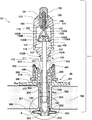
- FIG. 1 illustrates a Y-Z cross section elevation view of an embodiment of the self-adjusting perforating port.
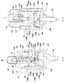
- FIG. 2A illustrates a Y-Z cross section of the non-actuated distal end of the handle member, with FIG. 2B , illustrating a Y-Z cross section of the actuated distal end of the handle member;
- FIG. 3A illustrates Y-Z cross section of enlarged section A in FIG. 1 of the expanding anchor during actuated insertion, with FIG. 3B illustrating Y-Z cross section of enlarged section A in FIG. 1 of the expanding anchor after expansion of the anchor, upon entering a body cavity;
- FIG. 4A illustrates an isometric view of enlarged section A in FIG. 1 of the expanding anchor during actuated insertion, with FIG. 4B illustrating an isometric view thereof after expansion of the anchor, upon entering a body cavity;
- FIGS. 5-9 illustrates a curved cross section sponge in FIG. 5 , angled sponge in FIG. 6 , split sponge embodiment at normal positioning relative to the body in FIG. 7 , tilted right in FIG. 8 , and tilted left in FIG. 9 .
- a device configured to automatically retract a perforating blade or guide wire upon entering a body cavity.
- the port is reversibly and selectably installed, or in other words, can be removed post insertion in a body cavity without causing damage to the body or necessitating additional incisions. In other words, removing the port provided herein will not increase the size of the aperture created in the body wall. Moreover, the port can be reinserted after further sterilization.
- Coupled refers to and comprises any direct or indirect, structural coupling, connection or attachment, or adaptation or capability for such a direct or indirect structural or operational coupling, connection or attachment, including integrally formed components and components which are coupled via or through another component or by the forming process.
- Indirect coupling may involve coupling through an intermediary member or adhesive, or abutting and otherwise resting against, whether frictionally or by separate means without any physical connection.
- directional or positional terms such as “top”, “bottom”, “upper,” “lower,” “side,” “front,” “frontal,” “forward,” “rear,” “rearward,” “back,” “trailing,” “above,” “below,” “left,” “right,” “radial,” “vertical,” “upward,” “downward,” “outer,” “inner,” “exterior,” “interior,” “intermediate,” etc., are merely used for convenience in describing the various embodiments of the present disclosure.
- the term “engaging element” refers in another embodiment to one or a plurality of coupled components, at least one of which is configured for releasably engaging another element. Thus, this term encompasses both single part engaging elements and multi-part-assemblies, for example the handle member as a whole.
- FIG. A more complete understanding of the self-adjusting perforating or guided ports described herein, their methods of use and kits comprising these ports, can be obtained by reference to the accompanying drawings.
- FIG. These figures (also referred to herein as “FIG.”) are merely schematic representations based on convenience and the ease of demonstrating the present disclosure, and are, therefore, not intended to indicate relative size, scale and dimensions of the devices or components thereof, their relative size relationship and/or to define or limit the scope of the exemplary embodiments.
- specific terms are used in the following description for the sake of clarity, these terms are intended to refer only to the particular structure of the embodiments selected for illustration in the drawings, and are not intended to define or limit the scope of the disclosure.
- FIG. In the drawings and the following description below, it is to be understood that like numeric designations refer to components of like function.
- cross sections and various views are referred to on normal orthogonal coordinate system having XYZ axis, such that Y axis refers to front-to-back, X axis refers to side-to-side, and Z axis refers to up-and-down.
- FIG. 1 illustrating an embodiment pressure sensitive, self-adjustable port 10 , comprising: handle member 100 comprising pressure sensitive actuation means.
- the pressure-sensitive actuation means comprise actuation rod 130 having a distal end configured to at least partially engage actuation knob 120 , and a distal end hingedly coupled to a hinged quadrilateral pawl.
- pawl or “pawl component” refers to a movable component which operates as a lever and which includes protuberances (or protrusions 136 A, 136 B), which engage a radial recess 115 .
- the term “pawl” refers to any hinged, pivoted, or adjustable structure adapted to temporarily and/or selectively engage an interfering structure, such as radial recess 115 .
- the hinged quadrilateral pawl comprising; first distal pawl member 133 A and second distal pawl member 133 B, each first 133 A and second 133 B distal pawl member having distal end 139 A, 139 B (not shown, see e.g., FIG. 2A, 2B ), and proximal end with protrusion or perturbation(s) 136 A, 136 B, each which is configured to engage radial recess 115 defined in proximal end 162 of chamber 110 defined in distal head portion 101 of handle member 100 , and distal end 139 A, 139 B hingedly coupled to actuation rod 130 .
- the quadrilateral pawl can generally be an isosceles trapezoid, with overhanging sides.
- the quadrilateral pawl can further comprise first proximal pawl member 134 A and second proximal pawl member 134 B, with first proximal pawl member 134 A having distal end 143 A (not shown, see e.g., FIG.
- first distal pawl member 133 A between distal end 139 A and proximal end 136 A of first distal pawl member 133 A, and proximal end 144 A hingedly coupled to perforating/guiding rod 140
- second proximal pawl member 134 B having distal end 139 B hingedly coupled to second distal pawl member 133 B between distal end 139 B and proximal end 136 B of second distal pawl member 133 B.
- the quadrilateral pawl further comprises pawl biaser 135 configured to bias distal end 143 A of first proximal pawl member 134 A to distal end 143 B of second proximal pawl member 134 B.
- stopper 137 disposed below proximal end 144 A, 144 B of first and second proximal pawl members 134 A, 134 B and above proximal end 162 of internal chamber 110 defined in head portion 101 of handle member 100 , configured to prevent proximal end 144 A, 144 B (not shown, see e.g., FIG. 2A, 2B ), of first and second proximal pawl members 134 A, 134 B from entering bore 107 defined in proximal end 162 of internal chamber 110 defined in head portion 101 of handle member 100 .
- the pressure-sensitive actuation means also comprises actuation biaser 105 operably coupled to actuation knob 120 having and actuation rod 130 .
- Actuation biaser 105 can be configured to distally bias actuation rod 130 into actuation knob's 120 well 121 , and actuation knob 120 distally from handle member 100 distal end.
- pressure-sensitive actuation means also comprises perforating rod 140 , wherein perforating rod 140 can be configured to extend beyond proximal end 223 of telescopic concentric cannula 220 .
- distal end 101 of handle member 100 defines cylindrical chamber 103 with an aperture 104 connecting cylindrical chamber 103 with internal chamber 110 .
- actuation rod 130 can have a flanged proximal end 131 terminating in coupling 132 , hingedly coupled to distal end(s) 139 A, 139 B (not shown, see e.g., FIG. 2A, 2B ), of distal pawl member(s) 133 A, 133 B.
- Flanged proximal end 131 can be configured to abut proximal end 162 of chamber 110 .
- the location of actuation knob 120 does not need to be axially concentric with handle member 100 , but can be radially disposed with proper mechanisms for transferring radial motion to axial motion to actuate the quadrilateral pawl.
- the shape of handle member can be varied.
- the pressure-sensitive actuation means also comprises shunt bobbin 20 .
- Shunt bobbin 20 can be an assembly comprised of various components that is selectably removable post insertion to a body cavity.
- the term “selectably removable” means that shunt bobbin 20 can be removed upon demand by a user of the port.
- the shunt can be a lined bore allowing movement of fluid from the body cavity to the outside under controlled environment.
- the shunt bobbin head can be flanged sleeve member 200 having elongated annular midportion 204 and a distal end having flanged portion 201 and neck portion 202 .
- the shunt bobbin assembly can further have telescopic concentric cannula 220 having flanged distal end 221 and elongated proximal end 222 , operably slidably coupled to distal flanged member 201 .
- Concentric flanged cannula 220 being distally biased.
- Concentric cannula 220 has open proximal end 223 .
- Sleeve member 200 having elongated annular midportion 204 accommodates telescopic concentric cannula 220 having flanged distal end 221 and elongated proximal end 222 , operably slidably coupled to distal flanged member 201 .
- the term “accommodate” means that telescopic concentric cannula 220 having flanged distal end 221 and elongated proximal end 222 , operably slidably coupled to distal flanged member 201 is configured at one or both ends to pass by sleeve member 200 having elongated annular midportion 204 and abut against the internal sidewall of elongated annular proximal end 204 .
- the term “slidably coupled” is used in its broadest sense to refer to elements which are coupled in a way that permits one element to slide or translate with respect to another element.
- Shunt bobbin 20 is comprised of distal end having flanged portion 201 and neck portion 202 as a distal portion of shunt bobbin 20 (outside the body), elongated annular midportion 204 as the stem of shunt bobbin 20 (spanning the body cavity wall in bore 705 ), terminating with expanding anchor sleeve 300 as the proximal portion of the shunt bobbin 20 .
- Flanged portion 201 can have a diameter that is at least three times ( 3 x ) larger than the outer diameter of sleeve member 200 having elongated annular proximal end 204 .
- the outer diameter of elongated annular midportion 204 can depend on the indication for which the port is employed and can be between about 4 mm (about 12 French (Fr)) and about 15 mm (>40 Fr).
- the internal diameter of concentric cannula 220 can be between about 10 mm and about 12 mm, to accommodate a drainage tube of 28 Fr.
- the internal diameter of concentric cannula 220 can be between about 3 mm and about 6 mm, to accommodate a drainage tube of 8-12 Fr.
- Flanged portion 201 can have a diameter of between about 12 mm and about 50 mm.
- the proximal end of shunt bobbin 20 can comprise expanding anchor sleeve 300 operably coupled to elongated proximal end 222 of telescopic concentric cannula 220 and elongated annular midportion 204 of the flanged member 200 .
- expanding anchor sleeve 300 is biased via adjusting biaser (e.g., a coil spring) 205 towards the flanged portion 201 .
- flanged distal end 201 of the flanged sleeve member 200 defines a distally open cylindrical bore 216 with a diameter configured to accommodate flanged distal end 221 of the telescopic concentric cannula 220 , and floor 217 defining a concentric proximal aperture 206 having a diameter configured to accommodate elongated proximal end 222 of telescopic concentric cannula 220 .
- adjusting biaser 205 can be disposed in distally open cylindrical bore 216 defined in flanged distal end 201 of the flanged sleeve member 200 between flanged distal end 221 of telescopic concentric cannula 220 and floor 217 of distally open cylindrical bore 216 .
- neck portion 202 of the distal end of the flanged sleeve member defines an external annular surface and an internal annular surface having lip 203 and is configured to releasably engage detent(s) 102 A, 102 B disposed on the outer surface of proximal portion 111 of the handle member 100 , having proximal end 112 .
- proximal portion's 111 proximal end 112 When inserted into distally open cylindrical bore 216 , proximal portion's 111 proximal end 112 abuts flanged distal end 221 of telescopic concentric cannula 220 , extending elongated proximal end 222 of telescopic concentric cannula 220 proximally beyond elongated annular midportion 204 of sleeve member 200 , thereby extending expandable anchor 300 against adjusting biaser 205 and forming a tube with a substantially uniform outer diameter, the tube being comprised of elongated annular midportion 204 of sleeve member 200 , expandable anchor sleeve 300 and elongated proximal end 222 of telescopic concentric cannula 220 .
- Lip 203 in the internal annular surface of neck portion 202 can then engage detent(s) 102 A, 102 B, maintaining expandable anchor sleeve 300 stretched.
- biaser 205 will bias flanged distal end 221 of telescopic concentric cannula 220 distally, causing elongated proximal end 222 of telescopic concentric cannula 220 to slidably translate distally, causing expandable anchor sleeve 300 to expand and engage bore 705 in the body cavity wall and adjust the distance between expanded anchor sleeve 300 and the bottom surface of flanged distal end 201 of the flanged sleeve member 200 .
- the distance between expanded anchor sleeve 300 and the bottom surface of flanged distal end 201 of the flanged sleeve member 200 can be indication specific and adapted to be between about 1.5 cm and about 10 cm.
- inserting a port after gut GSW may be longer than a port inserted to drain complex pneumothorax.
- kits provided herein comprising the ports described may comprise a variety of ports of varying lengths and varying diameters e.g., of flanged sleeve member's 200 flanged portion 201 , and internal diameter of elongated proximal end 222 of telescopic concentric cannula 220 .
- proximal portion's 111 proximal end 112 of handle member 100 can be inserted into distally open cylindrical bore 216 , abutting flanged distal end 221 of telescopic concentric cannula 220 , thereby extending elongated proximal end 222 of telescopic concentric cannula 220 proximally beyond elongated annular midportion 204 of sleeve member 200 —extending expandable anchor 300 against adjusting biaser 205 and forming a tube with a substantially uniform outer diameter and eliminating the proximal portion of shunt bobbin 20 which can then be removed through bore 705 .
- any rod, tube or member e.g., a finger
- any rod, tube or member rigid enough to overcome the force exerted by biaser 205 can be pressed against flanged distal end 221 of telescopic concentric cannula 220 and achieve the same result.
- Perforating blade 141 used in the devices methods and kits described herein can be movable between operational expanded position and retracted stowed position, and wherein once actuated the perforating blade being operably coupled to the pressure sensitive actuation means, wherein the, perforating blade is configured to retract upon entering a body cavity.
- perforating blade 141 can be selectably detachable from perforating/guiding rod 140 , such that for example, when inserting the port into a GSW, the blade can be detached and rod 140 becomes a guiding rod providing rigidity to elongated proximal end 222 of telescopic concentric cannula 220 .
- the term “selectably detachable” means that blade 141 can be detached from perforating/guiding rod 140 upon demand by a user without materially affecting the function of port 10 .
- Port 10 used in the methods and kits described herein can further comprise a diaphragm valve assembly operably coupled to the external surface of neck portion 202 of shunt bobbin's 20 sleeve member 200 , the diaphragm valve configured to rotate (or be angularly movable) between an open position and a closed position and be adapted to engage a tube (not shown, see e.g., FIG. 5 , for example a catheter, or drainage tube) while sealing port 10 around the engaged tube.
- a diaphragm valve assembly operably coupled to the external surface of neck portion 202 of shunt bobbin's 20 sleeve member 200 , the diaphragm valve configured to rotate (or be angularly movable) between an open position and a closed position and be adapted to engage a tube (not shown, see e.g., FIG. 5 , for example a catheter, or drainage tube) while sealing port 10 around the engaged tube.
- the diaphragm valve assembly can comprise an annular body member 400 being angularly movable relative to the neck portion 202 of shunt bobbin's 20 sleeve member 200 with annular body 400 having an external surface with distally disposed radial recess 401 and flexible closure sleeve 405 having a distal 406 and a proximal 407 annular mounting flanges (not shown) at opposite ends thereof, with a median mounting flange 408 (not shown disposed therebetween, the distal 406 and proximal 407 mounting flanges being engaged respectively in distally disposed radial recess 401 in the external surface of annular body member 400 , and median mounting flange 408 (not shown) operably coupled to radial recess 210 in the external surface of neck portion 202 of shunt bobbin's 20 sleeve member 200 , so as for annular body 400 to be angularly moveable relative to
- Flexible closure sleeve 405 can be made from any resilient material that is biocompatible, for example, silicone, latex, nitinol, polyurethane, polyethylene, polytetrafluoroethylene-coated latex or an equivalently biocompatible material.
- a pressure sensitive, self-adjustable port comprising: a handle member comprising pressure sensitive actuation means; a shunt bobbin operably coupled to the handle member, the shunt bobbin comprising: a flanged sleeve member having an elongated annular proximal end and a distal end having a flanged portion and a neck portion; and a telescopic concentric cannula having a flanged distal end and an elongated proximal end, operably slidably coupled to the distal flanged member, the concentric flanged cannula being distally biased; an expanding anchor operably coupled to the elongated proximal end of the telescopic concentric cannula and the elongated annular proximal end of the flanged member; and a perforating blade movable between operational expanded position and retracted stowed position, the
- pressure sensitive self-adjusting ports described herein are used in the methods provided herein.
- FIGS. 1, 2A, and 2B provided herein is a method of coupling port 10 described herein to a subject's site 700 across from a body cavity comprising: in a wound (e.g., 705 ), or a predetermined site 700 , positioning proximal end 223 of telescopic concentric cannula 220 forming the proximal end of pressure sensitive, self-adjustable surgical port 10 actuating the pressure sensitive actuation means by pressing actuation knob 120 , causing stopper 137 to abut proximal end 162 of chamber 110 thereby extending the perforating end 142 of perforating blade 141 , as well as creating a fulcrum (in other words, the point on which the quadrilateral pawl rests or is supported and on which it pivots), causing quadrilateral pawl's distal members 133 A, 133 B to move proximally while expanding distal members 133 A, 133 B proximal end
- detent(s) 102 A, 102 B can be disengaged from lip 203 (or, in another embodiment groove configured to receive and engage detents 102 A, 102 B, not shown).
- biaser 205 will bias flanged distal end 221 of telescopic concentric cannula 220 distally, causing elongated proximal end 222 of telescopic concentric cannula 220 to slidably translate distally, causing expandable anchor sleeve 300 to expand and engage bore 705 in the body cavity wall and adjust the distance between expanded anchor sleeve 300 and the bottom surface of flanged distal end 201 of the flanged sleeve member 200 .
- Handle member 100 as well as perforating/guiding rod 140 and blade 141 are then removed.
- FIGS. 3A, 3B illustrating expanding anchor sleeve 300 in insertion/retraction mode in FIG. 3A , and in expanded, anchoring mode in FIG. 3B .
- proximal portion's 111 proximal end 112 abuts flanged distal end 221 of telescopic concentric cannula 220 (see e.g., FIG. 1 ).
- the expandable anchor can further comprise flexible curtain 310 similarly having distal end 313 operably coupled to elongated proximal end 222 of telescopic concentric cannula 220 ; and distal end 312 operably coupled to elongated midportion 204 of sleeve member 200 with a free median portion 311 .
- biaser 205 Upon removal of handle member 100 as described above and as shown in FIG. 3B , biaser 205 (see e.g., FIG. 1 ) will bias flanged distal end 221 of telescopic concentric cannula 220 distally (see e.g., FIG.
- expandable anchor sleeve 300 can be comprised of a resilient cylinder having distal end 302 and proximal end 303 , with a median portion 301 (wall) defining a plurality of axial slots 320 and wherein slots 320 i can be slanted at angle ⁇ of between 1° and about 15° off the longitudinal axis x of handle member 100 , and/or elongated proximal end 222 of telescopic flanged concentric cannula 220 , slots 320 i forming strips 321 j therebetween.
- biaser 205 upon removal of handle member 100 as described above and as shown in FIG. 4B , biaser 205 (see e.g., FIG. 1 ) will bias flanged distal end 221 of telescopic concentric cannula 220 distally (see e.g., FIG.
- expandable curtain 310 is disposed above median portion 301 (wall) defining plurality of slanted axial slots 320 i such that upon expansion, the partial overlap of adjacent j th strips 321 j , can impart rigidity to expandable anchor sleeve 300 , while expandable curtain 310 imparts sealing characteristic to the expandable anchor forming the proximal portion of the adjustable shunt bobbin 20 .
- FIGS. 5-6 illustrating sponge 500 having bottom surface 501 and an upper surface 504 operably coupled to a bottom surface of flanged distal end 201 of flanged sleeve member 200 , sponge 500 configured to be sandwiched between the bottom surface of flanged distal end 201 of flanged sleeve member 200 , and the body surface 700 .
- catheter 600 having at least one distal collection aperture 601 engaged in diaphragm valve having annular body 400 , and flexible closure sleeve 405 .
- sponge's 500 bottom surface 501 can define a cross section that is arcuate or curved ( FIG.
- sponge 500 can have bottom surface 501 that is slanted, such that when abutting the body site 700 bottom surface 501 can form a predetermined angle.
- the angle can be indication-specific; for example, angling the catheter for hemothorax towards the ribs while angle of approach for other indications may be different.
- Sponge 500 can be made impregnated with a composition comprising an analgesic, an antiseptic, a disinfectant, a medication, an adhesive (e.g., pressure-sensitive adhesive) or a composition comprising one or more of the forgoing.
- the angle formed between the longitudinal axis of the port and the body surface can be between about 30° and about 90°, for example, 45°.
- the foam can be, for example an open-cell poly(urethane) foam, or for example, be made from cellulose, carboxylated butadiene-styrene rubber, polyester foams, hydrophilic epoxy foams or polyacrylate.
- FIGS. 7-9 illustrating an embodiment wherein the sponge having the normal bottom surface relative to the port's longitudinal axis is comprised of a first and a second sponge members 500 , 502 , being rotatably movable relative to each other, first sponge member 500 abutting second sponge member 502 along a complimentary surface 501 , 503 defining a slanted cross section relative to longitudinal axis x (see e.g., FIG. 1 ), of port 10 .
- the port can be inserted at a normal ( FIG. 7 ), while for example, clock-wise rotation will tilt the port in one direction (see e.g., FIG.
- rotateably coupled is used in its broadest sense to refer to elements which are coupled in a way that permits one element to rotate or pivot with respect to another element.
- kits comprising port 10 as described herein; a catheter; optionally an analgesic; and optionally a disinfectant.
- diaphragm closure comprising a first annular member, having an internal surface, an external surface, a distal end and a proximal end, the distal end of the external surface defining a radial channel, wherein the internal surface is adapted to operably couple to a predetermined liquid vessel; a second annular member having an internal surface, an external surface, a distal end and a proximal end, the distal end of the internal surface defining a radial channel, wherein the internal surface is operably coupled to the external surface of the first annular member; a flexible closure sleeve having a distal and a proximal annular mounting flanges at opposite ends thereof, with a median mounting flange disposed therebetween, the distal and proximal mounting flanges being engaged respectively in the distally disposed radial channel in the internal surface of the second annular member, and the median mounting flange operably coupled to the radial recess in the external
- the predetermined liquid vessel used in conjunction with the diaphragm closure described can be liquid vessel having a cylindrical distal opening having an interrupted threading thereon (e.g., seltzer bottle), and wherein the internal surface of the first annular member defines a complementary threading therein.
- a pressure sensitive, self-adjustable port comprising: a handle member comprising pressure sensitive actuation means; a shunt bobbin operably coupled to the handle member, the shunt bobbin comprising: a flanged sleeve member having an elongated annular proximal end and a distal end having a flanged portion and a neck portion; and a telescopic concentric cannula having a flanged distal end and an elongated proximal end, operably slidably coupled to the distal flanged member, the concentric flanged cannula being distally biased; an expanding anchor operably coupled to the elongated proximal end of the telescopic concentric cannula and the elongated annular proximal end of the flanged member; and a perforating blade movable between operational expanded position and retracted stowed position, the perforating blade being
- a method of coupling a surgical port to a subject's site across from a body cavity comprising: in a wound, or a predetermined site, positioning the proximal end of a pressure sensitive, self-adjustable surgical port, comprising a handle member comprising pressure sensitive actuation means; a shunt bobbin operably coupled to the handle member, the shunt bobbin comprising: a flanged sleeve member having an elongated proximal end and a distal end having a flanged portion and a neck portion; and a telescopic concentric cannula having a flanged distal end and an elongated proximal end, operably slidably coupled to the distal flanged member, the concentric flanged cannula being distally biased; an expanding anchor operably coupled to the elongated proximal end of the telescopic concentric cannula and the elong
- kits comprising: the pressure sensitive, self-adjusting surgical port described herein, a catheter; optionally an analgesic; and optionally a disinfectant.
- a diaphragm closure comprising
- a first annular member having an internal surface, an external surface, a distal end and a proximal end, the distal end of the external surface defining a radial channel, wherein the internal surface is adapted to operably couple to a predetermined liquid vessel; a second annular member having an internal surface, an external surface, a distal end and a proximal end, the distal end of the internal surface defining a radial channel, wherein the internal surface is operably coupled to the external surface of the first annular member; a flexible closure sleeve having a distal and a proximal annular mounting flanges at opposite ends thereof, with a median mounting flange disposed therebetween, the distal and proximal mounting flanges being engaged respectively in the distally disposed radial channel in the internal surface of the second annular member, and the median mounting flange operably coupled to the radial recess in the external surface of the first annular member, so as to be angularly move
Landscapes
- Health & Medical Sciences (AREA)
- Life Sciences & Earth Sciences (AREA)
- Heart & Thoracic Surgery (AREA)
- Surgery (AREA)
- Veterinary Medicine (AREA)
- Public Health (AREA)
- General Health & Medical Sciences (AREA)
- Engineering & Computer Science (AREA)
- Biomedical Technology (AREA)
- Animal Behavior & Ethology (AREA)
- Molecular Biology (AREA)
- Medical Informatics (AREA)
- Nuclear Medicine, Radiotherapy & Molecular Imaging (AREA)
- Pathology (AREA)
- Pulmonology (AREA)
- Anesthesiology (AREA)
- Hematology (AREA)
- Gastroenterology & Hepatology (AREA)
- Biophysics (AREA)
- Vascular Medicine (AREA)
- Surgical Instruments (AREA)
- Specific Sealing Or Ventilating Devices For Doors And Windows (AREA)
- Casting Support Devices, Ladles, And Melt Control Thereby (AREA)
Abstract
Description
Claims (16)
Priority Applications (1)
| Application Number | Priority Date | Filing Date | Title |
|---|---|---|---|
| US16/090,392 US10857341B2 (en) | 2016-03-31 | 2017-03-31 | Reversibly removable self-adjusting port |
Applications Claiming Priority (3)
| Application Number | Priority Date | Filing Date | Title |
|---|---|---|---|
| US201662316082P | 2016-03-31 | 2016-03-31 | |
| PCT/US2017/025310 WO2017173231A1 (en) | 2016-03-31 | 2017-03-31 | Reversibly removable self-adjusting port |
| US16/090,392 US10857341B2 (en) | 2016-03-31 | 2017-03-31 | Reversibly removable self-adjusting port |
Publications (2)
| Publication Number | Publication Date |
|---|---|
| US20190117949A1 US20190117949A1 (en) | 2019-04-25 |
| US10857341B2 true US10857341B2 (en) | 2020-12-08 |
Family
ID=59966508
Family Applications (1)
| Application Number | Title | Priority Date | Filing Date |
|---|---|---|---|
| US16/090,392 Active - Reinstated 2037-12-27 US10857341B2 (en) | 2016-03-31 | 2017-03-31 | Reversibly removable self-adjusting port |
Country Status (4)
| Country | Link |
|---|---|
| US (1) | US10857341B2 (en) |
| EP (1) | EP3435898B1 (en) |
| ES (1) | ES2965713T3 (en) |
| WO (1) | WO2017173231A1 (en) |
Families Citing this family (3)
| Publication number | Priority date | Publication date | Assignee | Title |
|---|---|---|---|---|
| AU2019389110B2 (en) * | 2018-11-30 | 2025-07-24 | Quick Tube Medical, Llc | Method and apparatus for treating tension pneumothorax using a rapid deployment chest port |
| CN111151174A (en) * | 2020-01-08 | 2020-05-15 | 丁许 | Oily fluid is agitator for continuous mixing |
| CN112842408B (en) * | 2021-02-04 | 2022-11-01 | 中国人民解放军陆军军医大学第一附属医院 | Auxiliary propelling device for lumbar puncture needle |
Citations (1)
| Publication number | Priority date | Publication date | Assignee | Title |
|---|---|---|---|---|
| US8435174B2 (en) * | 2009-12-11 | 2013-05-07 | Ethicon Endo-Surgery, Inc. | Methods and devices for accessing a body cavity |
Family Cites Families (7)
| Publication number | Priority date | Publication date | Assignee | Title |
|---|---|---|---|---|
| US785066A (en) * | 1903-12-16 | 1905-03-14 | Edwin H Ludeman | Nozzle for turbine-engines. |
| US5707362A (en) | 1992-04-15 | 1998-01-13 | Yoon; Inbae | Penetrating instrument having an expandable anchoring portion for triggering protrusion of a safety member and/or retraction of a penetrating member |
| US6986775B2 (en) * | 2002-06-13 | 2006-01-17 | Guided Delivery Systems, Inc. | Devices and methods for heart valve repair |
| US7798998B2 (en) * | 2006-10-06 | 2010-09-21 | Surgiquest, Inc. | Elastically deformable surgical access device |
| US20090043314A1 (en) * | 2007-07-16 | 2009-02-12 | The Cleveland Clinic Foundation | Access device for body tissue and method of using same |
| EP2704650A2 (en) * | 2011-05-02 | 2014-03-12 | Applied Medical Resources Corporation | Low-profile surgical universal access port |
| US8496632B2 (en) * | 2011-08-25 | 2013-07-30 | Ethicon Endo-Surgery, Inc. | Surgical access device with adjustable cannula |
-
2017
- 2017-03-31 EP EP17776751.4A patent/EP3435898B1/en active Active
- 2017-03-31 ES ES17776751T patent/ES2965713T3/en active Active
- 2017-03-31 WO PCT/US2017/025310 patent/WO2017173231A1/en not_active Ceased
- 2017-03-31 US US16/090,392 patent/US10857341B2/en active Active - Reinstated
Patent Citations (1)
| Publication number | Priority date | Publication date | Assignee | Title |
|---|---|---|---|---|
| US8435174B2 (en) * | 2009-12-11 | 2013-05-07 | Ethicon Endo-Surgery, Inc. | Methods and devices for accessing a body cavity |
Also Published As
| Publication number | Publication date |
|---|---|
| EP3435898A1 (en) | 2019-02-06 |
| EP3435898B1 (en) | 2023-10-04 |
| ES2965713T3 (en) | 2024-04-16 |
| EP3435898A4 (en) | 2020-01-01 |
| WO2017173231A1 (en) | 2017-10-05 |
| US20190117949A1 (en) | 2019-04-25 |
Similar Documents
| Publication | Publication Date | Title |
|---|---|---|
| EP2621348B1 (en) | Natural orifice surgery system | |
| AU2005200101B2 (en) | Medical device for providing access | |
| EP1675500B1 (en) | Expandible surgical access device | |
| US7691089B2 (en) | Adjustable trocar washer | |
| AU2005200103B2 (en) | Method for accessing an operating space | |
| US9066717B2 (en) | Suture passer guides and related kits and methods | |
| US5817062A (en) | Trocar | |
| US10004533B2 (en) | Surgical tools and system for safely accessing body cavities and methods of using the same | |
| EP2609880A1 (en) | Wound protector with reinforced ring | |
| KR20100100706A (en) | Surgical access devices and methods providing seal movement in predefined paths | |
| US20150087913A1 (en) | Natural orifice access device | |
| JPH0857056A (en) | Valve device for cannula assembly | |
| KR20100100707A (en) | Surgical access devices and methods providing seal movement in predefined movement regions | |
| CN107049440B (en) | Variable-diameter sleeve assembly with direct pushing structure and puncture outfit | |
| US20190008551A1 (en) | Surgical tools and system for safely accessing body cavities and methods of using the same | |
| US10857341B2 (en) | Reversibly removable self-adjusting port | |
| EP2838436B1 (en) | Natural orifice surgery system | |
| US20250352391A1 (en) | Retractable backflush instrument | |
| EP2138116B1 (en) | Trocar assembly with radially moveable housing | |
| JP2002325769A (en) | Tool for medical treatment | |
| EP3909531B1 (en) | Surgical access device with air release mechanism | |
| JP4832763B2 (en) | Access medical device and medical procedure execution method | |
| US11583315B2 (en) | Surgical access device including variable length cannula |
Legal Events
| Date | Code | Title | Description |
|---|---|---|---|
| FEPP | Fee payment procedure |
Free format text: ENTITY STATUS SET TO UNDISCOUNTED (ORIGINAL EVENT CODE: BIG.); ENTITY STATUS OF PATENT OWNER: SMALL ENTITY |
|
| FEPP | Fee payment procedure |
Free format text: ENTITY STATUS SET TO SMALL (ORIGINAL EVENT CODE: SMAL); ENTITY STATUS OF PATENT OWNER: SMALL ENTITY |
|
| STPP | Information on status: patent application and granting procedure in general |
Free format text: DOCKETED NEW CASE - READY FOR EXAMINATION |
|
| STCF | Information on status: patent grant |
Free format text: PATENTED CASE |
|
| FEPP | Fee payment procedure |
Free format text: MAINTENANCE FEE REMINDER MAILED (ORIGINAL EVENT CODE: REM.); ENTITY STATUS OF PATENT OWNER: SMALL ENTITY |
|
| LAPS | Lapse for failure to pay maintenance fees |
Free format text: PATENT EXPIRED FOR FAILURE TO PAY MAINTENANCE FEES (ORIGINAL EVENT CODE: EXP.); ENTITY STATUS OF PATENT OWNER: SMALL ENTITY |
|
| PRDP | Patent reinstated due to the acceptance of a late maintenance fee |
Effective date: 20250115 |
|
| FEPP | Fee payment procedure |
Free format text: PETITION RELATED TO MAINTENANCE FEES FILED (ORIGINAL EVENT CODE: PMFP); ENTITY STATUS OF PATENT OWNER: SMALL ENTITY Free format text: PETITION RELATED TO MAINTENANCE FEES GRANTED (ORIGINAL EVENT CODE: PMFG); ENTITY STATUS OF PATENT OWNER: SMALL ENTITY Free format text: SURCHARGE, PETITION TO ACCEPT PYMT AFTER EXP, UNINTENTIONAL. (ORIGINAL EVENT CODE: M2558); ENTITY STATUS OF PATENT OWNER: SMALL ENTITY |
|
| MAFP | Maintenance fee payment |
Free format text: PAYMENT OF MAINTENANCE FEE, 4TH YR, SMALL ENTITY (ORIGINAL EVENT CODE: M2551); ENTITY STATUS OF PATENT OWNER: SMALL ENTITY Year of fee payment: 4 |
|
| STCF | Information on status: patent grant |
Free format text: PATENTED CASE |
|
| FP | Lapsed due to failure to pay maintenance fee |
Effective date: 20241208 |