US10851760B2 - Liquid potential energy increasing device - Google Patents
Liquid potential energy increasing device Download PDFInfo
- Publication number
- US10851760B2 US10851760B2 US16/137,387 US201816137387A US10851760B2 US 10851760 B2 US10851760 B2 US 10851760B2 US 201816137387 A US201816137387 A US 201816137387A US 10851760 B2 US10851760 B2 US 10851760B2
- Authority
- US
- United States
- Prior art keywords
- liquid
- potential energy
- receiving trough
- main body
- energy increasing
- Prior art date
- Legal status (The legal status is an assumption and is not a legal conclusion. Google has not performed a legal analysis and makes no representation as to the accuracy of the status listed.)
- Active, expires
Links
Images


Classifications
-
- F—MECHANICAL ENGINEERING; LIGHTING; HEATING; WEAPONS; BLASTING
- F04—POSITIVE - DISPLACEMENT MACHINES FOR LIQUIDS; PUMPS FOR LIQUIDS OR ELASTIC FLUIDS
- F04B—POSITIVE-DISPLACEMENT MACHINES FOR LIQUIDS; PUMPS
- F04B19/00—Machines or pumps having pertinent characteristics not provided for in, or of interest apart from, groups F04B1/00 - F04B17/00
-
- F—MECHANICAL ENGINEERING; LIGHTING; HEATING; WEAPONS; BLASTING
- F03—MACHINES OR ENGINES FOR LIQUIDS; WIND, SPRING, OR WEIGHT MOTORS; PRODUCING MECHANICAL POWER OR A REACTIVE PROPULSIVE THRUST, NOT OTHERWISE PROVIDED FOR
- F03B—MACHINES OR ENGINES FOR LIQUIDS
- F03B17/00—Other machines or engines
-
- F—MECHANICAL ENGINEERING; LIGHTING; HEATING; WEAPONS; BLASTING
- F03—MACHINES OR ENGINES FOR LIQUIDS; WIND, SPRING, OR WEIGHT MOTORS; PRODUCING MECHANICAL POWER OR A REACTIVE PROPULSIVE THRUST, NOT OTHERWISE PROVIDED FOR
- F03G—SPRING, WEIGHT, INERTIA OR LIKE MOTORS; MECHANICAL-POWER PRODUCING DEVICES OR MECHANISMS, NOT OTHERWISE PROVIDED FOR OR USING ENERGY SOURCES NOT OTHERWISE PROVIDED FOR
- F03G7/00—Mechanical-power-producing mechanisms, not otherwise provided for or using energy sources not otherwise provided for
- F03G7/10—Alleged perpetua mobilia
- F03G7/104—Alleged perpetua mobilia continuously converting gravity into usable power
- F03G7/111—Alleged perpetua mobilia continuously converting gravity into usable power using magnets, e.g. gravo-magnetic motors
-
- F—MECHANICAL ENGINEERING; LIGHTING; HEATING; WEAPONS; BLASTING
- F03—MACHINES OR ENGINES FOR LIQUIDS; WIND, SPRING, OR WEIGHT MOTORS; PRODUCING MECHANICAL POWER OR A REACTIVE PROPULSIVE THRUST, NOT OTHERWISE PROVIDED FOR
- F03G—SPRING, WEIGHT, INERTIA OR LIKE MOTORS; MECHANICAL-POWER PRODUCING DEVICES OR MECHANISMS, NOT OTHERWISE PROVIDED FOR OR USING ENERGY SOURCES NOT OTHERWISE PROVIDED FOR
- F03G7/00—Mechanical-power-producing mechanisms, not otherwise provided for or using energy sources not otherwise provided for
- F03G7/10—Alleged perpetua mobilia
- F03G7/119—Alleged perpetua mobilia amplifying power, torque or energy
-
- F—MECHANICAL ENGINEERING; LIGHTING; HEATING; WEAPONS; BLASTING
- F05—INDEXING SCHEMES RELATING TO ENGINES OR PUMPS IN VARIOUS SUBCLASSES OF CLASSES F01-F04
- F05B—INDEXING SCHEME RELATING TO WIND, SPRING, WEIGHT, INERTIA OR LIKE MOTORS, TO MACHINES OR ENGINES FOR LIQUIDS COVERED BY SUBCLASSES F03B, F03D AND F03G
- F05B2280/00—Materials; Properties thereof
- F05B2280/50—Intrinsic material properties or characteristics
- F05B2280/5008—Magnetic properties
Definitions
- the invention relates to a liquid energy increasing device. More particularly, the invention relates to a device capable of increasing liquid's potential energy.
- the invention provides a liquid potential energy increasing device which generates power in the form of renewable energy.
- a liquid potential energy increasing device includes at least one potential energy increasing unit, and the at least one potential energy increasing unit includes a first receiving trough, a second receiving trough, a liquid absorbing structure, a first magnetic component, and a second magnetic component.
- the first receiving trough may receive a liquid.
- the second receiving trough is disposed above the first receiving trough.
- the liquid absorbing structure includes a main body portion and an extending portion. The main body portion is located in the second receiving trough, and the extending portion is connected to the main body portion and extends to the first receiving trough.
- the first magnetic component and the second magnetic component are respectively disposed on the second receiving trough and the main body portion.
- the main body portion is positioned at a first position on the second receiving trough by a magnetic attraction between the first magnetic component and the second magnetic component.
- the extending portion is adapted to convey the liquid in the first receiving trough into the main body portion.
- the main body portion when the liquid in the main body portion is at least partially released into the second receiving trough so that the sum of the weight of the main body portion and the weight of the liquid in the main body portion is less than the magnetic attraction, the main body portion is returned to the first position by the magnetic attraction.
- a number of the at least one potential energy increasing unit of the liquid potential energy increasing device is plural.
- the second receiving trough of at least one of the potential energy increasing units and the first receiving trough of another one of the potential energy increasing units are located at a same height and in communication with each other.
- the liquid potential energy increasing device includes a supporting structure.
- the supporting structure and the first receiving trough of one of the potential energy increasing units are located at a same height, and the first receiving trough of another one of the potential energy increasing units is supported on the supporting structure.
- the extending portion of the at least one potential energy increasing unit and the extending portion of another one of the potential energy increasing units are respectively located at two opposite sides of the liquid potential energy increasing device.
- a number of the at least one potential energy increasing unit of the liquid potential energy increasing device is plural.
- the potential energy increasing units are connected to one another in a horizontal direction.
- the first receiving trough of each of the potential energy increasing units and the first receiving trough of another one of the potential energy increasing units are located at a same height and in communication with each other.
- the second receiving trough of each of the potential energy increasing units and the second receiving trough of another one of the potential energy increasing units are located at a same height and in communication with each other.
- the second receiving trough of the liquid potential energy increasing device includes a trough body and a rack body.
- the trough body may receive the liquid.
- the rack body is disposed on the trough body and has a top wall, and the first magnetic component is disposed on the top wall.
- the main body portion of the liquid potential energy increasing device includes a liquid absorbing component, a plate, and a frame.
- the extending portion is connected to the liquid absorbing component.
- a periphery of the liquid absorbing component is sandwiched between the plate and the frame.
- the liquid absorbing component protrudes from the frame, and the second magnetic component is disposed on the plate.
- a partial segment of the extending portion of the liquid potential energy increasing device is sandwiched between the plate and the liquid absorbing component.
- the extending portion and the liquid absorbing component of the liquid potential energy increasing device are sponges.
- the extending portion and the liquid absorbing component of the liquid potential energy increasing device are integrally formed.
- the first magnetic component and the second magnetic component of the liquid potential energy increasing device are magnets.
- the second receiving trough of the liquid potential energy increasing device includes a trough body and an impact plate.
- the impact plate is disposed inside the trough body and is located at the second position, the main body portion is adapted to hit the impact plate, and the liquid on the impact plate is adapted to be released into the trough body.
- the impact plate of the liquid potential energy increasing device has at least one opening, and the liquid on the impact plate is adapted to be released into the trough body through the opening.
- one of the main body portion and the impact plate of the liquid potential energy increasing device has at least one recess.
- the other one of the main body portion and the impact plate has at least one protrusion.
- the protrusion and the recess are adapted to collide with each other.
- the impact plate of the liquid potential energy increasing device includes a plurality of capillaries.
- the liquid potential energy increasing device includes a float.
- the float is disposed inside the first receiving trough and partially extends outside the first receiving trough.
- the first receiving trough of the liquid potential energy increasing device includes a trough body.
- the trough body is adapted to receive the liquid.
- the extending portion of the liquid absorbing structure is located at a first region of the trough body, and the first receiving trough has at least one protruding portion located at a second region of the trough body.
- the liquid located in the first receiving trough is delivered upwards to the main body portion in the second receiving trough through the extending portion of the liquid absorbing structure.
- the main body portion absorbs the liquid
- the main body portion is heavy enough to move by gravity against the magnetic attraction of the magnetic components and hits the second receiving trough, so that the liquid in the main body portion is partially released into the second receiving trough.
- the main body portion is reduced in weight due to release of liquid therefrom; thus the main body portion is returned by the magnetic attraction.
- the liquid in the first receiving trough may be continuously conveyed to the second receiving trough located at a relatively high position by a capillary phenomenon of the liquid absorbing structure, a magnetic force of the magnetic components, and a gravitational force caused by the weight of the main body portion and the weight of the liquid itself in the main body portion, thereby achieving an increase in potential energy.
- the liquid potential energy increasing device can achieve an increase in potential energy without using any externally applied force or energy source as described above; therefore, unlike those renewable energy devices using energy source such as solar or wind and required to be implemented outdoors, the liquid potential energy increasing device provided by the embodiments of the invention may be implemented in indoor environments and may be invulnerable to weather and geographical conditions.
- FIG. 1 is a perspective view of a liquid potential energy increasing device according to an embodiment of the invention.
- FIG. 2 is an exploded view of the liquid potential energy increasing device illustrated in FIG. 1 .
- FIG. 3A and FIG. 3B are schematic views of movement of the liquid potential energy increasing device illustrated in FIG. 1 .
- FIG. 4 is an exploded view of the liquid absorbing structure illustrated in FIG. 1 .
- FIG. 5 is a perspective view of a trough body of the second receiving trough illustrated in FIG. 1 .
- FIG. 6 is a perspective view of an impact plate illustrated in FIG. 1 .
- FIG. 7 is a perspective view of the first receiving trough according to another embodiment of the invention.
- FIG. 8 is a perspective view of a liquid absorbing component and an impact plate according to another embodiment of the invention.
- FIG. 9 is a bottom view of the impact plate illustrated in FIG. 8 .
- FIG. 10 is a perspective view of a liquid absorbing component and an impact plate according to another embodiment of the invention.
- FIG. 11 is a perspective view of an impact plate according to another embodiment of the invention.
- FIG. 12 is a perspective view of a liquid potential energy increasing device according to another embodiment of the invention.
- FIG. 13 is a perspective view of a liquid potential energy increasing device according to another embodiment of the invention.
- FIG. 14 is a perspective view of a guiding plate illustrated in FIG. 12 .
- FIG. 1 is a perspective view of a liquid potential energy increasing device according to an embodiment of the invention.
- FIG. 2 is an exploded view of the liquid potential energy increasing device illustrated in FIG. 1 .
- a liquid potential energy increasing device 1 of the present embodiment includes at least one potential energy increasing unit 10 .
- the at least one potential energy increasing unit 10 includes a first receiving trough 100 , a second receiving trough 200 , a liquid absorbing structure 400 , a first magnetic component 500 , and a second magnetic component 600 .
- the first receiving trough 100 may receive a liquid (e.g., water).
- the first receiving trough 100 has a drainage hole 140 therein, and the top of the drainage hole 140 has a certain height to discharge excess liquid out of the first receiving trough 100 .
- the second receiving trough 200 is disposed above the first receiving trough 100 .
- the liquid absorbing structure 400 includes a main body portion 410 and an extending portion 420 .
- the main body portion 410 is located in the second receiving trough 200 , and the extending portion 420 is connected to the main body portion 410 and extends to the first receiving trough 100 .
- the first magnetic component 500 and the second magnetic component 600 are disposed on the second receiving trough 200 and the main body portion 410 , respectively.
- the main body portion 410 is positioned at a first position on the second receiving trough 200 by a magnetic attraction between the first magnetic component 500 and the second magnetic component 600 .
- FIG. 3A and FIG. 3B are schematic views of movement of the liquid potential energy increasing device illustrated in FIG. 1 .
- the extending portion 420 of the present embodiment is adapted to convey the liquid in the first receiving trough 100 into the main body portion 410 .
- the magnetic attraction is insufficient to keep the main body portion 410 positioned at the first position.
- the main body portion 410 moves from the first position shown in FIG. 1 and FIG. 3A to a second position on the second receiving trough 200 as shown in FIG.
- the main body portion 410 falls down from the first position shown in FIG. 1 and FIG. 3A to the second position on the second receiving trough 200 shown in FIG. 3B by gravity, but the invention is not limited thereto.
- the main body portion 410 may hit the second receiving trough 200 by gravity in a pendulum manner, or may strike the second receiving trough 200 by gravity with other appropriate movements.
- the liquid in the first receiving trough 100 may be continuously conveyed to the second receiving trough 200 located at a relatively high position by a capillary phenomenon of the liquid absorbing structure 400 , a magnetic force of the magnetic components, and a gravitational force caused by the weight of the main body portion 410 and the weight of the liquid itself in the main body portion 410 , thereby achieving an increase in potential energy.
- liquid potential energy increasing device 1 can achieve an increase in potential energy without using any externally applied force or energy source as described above; therefore, unlike those renewable energy devices using energy source such as solar or wind and required to be implemented outdoors, the liquid potential energy increasing device 1 of the present embodiment may be implemented in indoor environments and may be invulnerable to weather and geographical conditions.
- the magnetic attraction between the first magnetic component 500 and the second magnetic component 600 decreases as the distance between the first position and the second position increases.
- the distance between the first position and the second position may be appropriately adjusted according to design requirements. Note that although potential energy is lost as the main body portion 410 moves from the first position to the second position during the aforementioned movements, since the second position is still higher than the first receiving trough, the potential energy of the liquid increases eventually.
- liquid potential energy increasing device 1 of the present embodiment achieves an increase of the liquid's potential energy through the magnetic attractive force, the capillary phenomenon, and the gravitational force as described above, which are means of increasing potential energy and can be implemented according to the invention.
- FIG. 4 is an exploded view of the liquid absorbing structure illustrated in FIG. 1 .
- the liquid absorbing structure 400 includes the main body portion 410 and the extending portion 420 .
- the main body portion 410 includes a liquid absorbing component 411 , a plate 412 , and a frame 413 .
- the extending portion 420 is connected to the liquid absorbing component 411 .
- a periphery of the liquid absorbing component 411 is sandwiched between the plate 412 and the frame 413 .
- the liquid absorbing component 411 protrudes from the frame 413 , and the second magnetic component 600 is disposed on the plate 412 .
- a partial segment of the extending portion 420 of the present embodiment is sandwiched between the plate 412 and the liquid absorbing component 411 .
- the extending portion 420 and the liquid absorbing component 411 may be sponges, and the extending portion 420 and the liquid absorbing component 411 may be an integrally-formed structure.
- the first magnetic component 500 and the second magnetic component 600 may be magnets.
- the liquid absorbing structure 400 of the present embodiment may be replaced from the backside of the device. Hence, if maintenance is needed, only the liquid absorbing structure 400 is required to be replaced, thereby allowing convenient replacement and maintenance works.
- FIG. 5 is a perspective view of a trough body of the second receiving trough illustrated in FIG. 1 .
- FIG. 6 is a perspective view of an impact plate illustrated in FIG. 1 .
- the second receiving trough 200 of the present embodiment includes a trough body 210 , a rack body 220 , and an impact plate 230 .
- the trough body 210 is adapted to receive the liquid.
- the rack body 220 is disposed on the trough body 210 and has a top wall 221
- the first magnetic component 500 is disposed on the top wall 221 .
- the impact plate 230 is disposed inside the trough body 210 and is located at the second position.
- the impact plate 230 has at least one opening 231 and a plurality of positioning holes 234 .
- the trough body 210 further includes a plurality of engaging components 213 , and the engaging components 213 are adapted to be engaged with the rack body 220 .
- the second receiving trough 200 further includes a plurality of positioning poles 214 and a baffle 215 .
- the positioning poles 214 may be inserted into the positioning holes 234 of the impact plate 230 , so that the impact plate 230 is supported and positioned by the positioning poles 214 .
- the impact plate 230 may be positioned at a fixed position as the baffle 215 is disposed.
- the first receiving trough 100 and the second receiving trough 200 may be engaged through the engaging components or through other appropriate structures.
- the impact plate 230 of the present embodiment may be replaced from the backside of the device. Hence, if maintenance is needed, only the impact plate 230 is required to be replaced, thereby allowing convenient replacement and maintenance works.
- FIG. 7 is a perspective view of the first receiving trough according to another embodiment of the invention.
- the first receiving trough 100 of the present embodiment includes a float 130 .
- the float 130 is disposed inside the first receiving trough 100 and partially extends outside the first receiving trough 100 .
- a user may determine whether an amount of the liquid in the first receiving trough 100 is normal according to a height of the float 130 , so as to ascertain abnormal conditions in the liquid potential energy increasing device 1 relating to malfunction.
- the trough body 110 of the first receiving trough 100 is adapted to receive the liquid.
- the extending portion 420 of the liquid absorbing structure 400 is located at a first region 111 of the trough body 110 , and the first receiving trough 100 has at least one protruding portion 120 located at a second region 112 of the trough body 110 .
- the protruding portion 120 the liquid may be concentrated in the first region 111 where the extending portion 420 is located, so that the liquid potential energy increasing device 1 may operate smoothly using less amount of liquid, thereby achieving the effect of liquid saving.
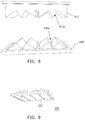
- FIG. 8 is a perspective view of a liquid absorbing component and an impact plate according to another embodiment of the invention.
- FIG. 9 is a bottom view of the impact plate illustrated in FIG. 8 .
- a difference between the present embodiment and the foregoing embodiment includes that a liquid absorbing component 411 ′ of the present embodiment has a plurality of protrusions 411 a , and an impact plate 230 ′ has a plurality of recesses 230 a .
- the impact area where the liquid absorbing component 411 ′ and the impact plate 230 ′ can collide with each other increases, thereby increasing the amount of liquid released after the liquid absorbing component 411 ′ collides.
- the openings 231 ′ of the impact plate 230 may be designed along with a structure of the recesses 230 a to fit the structural design of the recesses 230 a.
- FIG. 10 is a perspective view of a liquid absorbing component and an impact plate according to another embodiment of the invention.
- a difference between the present embodiment and the foregoing embodiment includes that a number of protrusions 411 b of a liquid absorbing component 411 ′′ and a number of recesses 230 b of an impact plate 230 ′′ in the present embodiment are more than those shown in FIG. 8 so as to further increase the impact area of the liquid absorbing component 411 ′′ and the impact plate 230 ′′, thereby adding the amount of liquid released after the liquid absorbing component 411 ′′ collides.
- the impact plate 230 ′′ of the present embodiment includes two components 2301 and 2302 , but the invention is not limited thereto.
- a material, a dimension, a structure, a shape (matched with the impact plate), and an elastic modulus of the main body portion 410 ′′ may be adjusted and simultaneously modify the foregoing parameters of the impact plate 230 ′′ to improve the collision effect.
- FIG. 11 is a perspective view of an impact plate according to another embodiment of the invention.
- an impact plate 230 ′′′ of the present embodiment may be composed by a plurality of capillaries 232 , thereby allowing a better drainage efficiency.
- FIG. 12 is a perspective view of a liquid potential energy increasing device according to another embodiment of the invention.
- a liquid potential energy increasing device 1 ′ of the present embodiment has a plurality of potential energy increasing units 10 (shown as three units) and further includes a supporting structure 300 .
- the supporting structure 300 and the first receiving trough 100 of the potential energy increasing unit 10 are located at a same height.
- the first receiving trough 100 of the potential energy increasing unit 10 is supported on the supporting structure 300
- the first receiving trough 100 of the potential energy increasing unit 10 illustrated at the right side of FIG.
- the potential energy increasing units 10 are alternately stacked with one another in a height direction. As such, the liquid may be delivered to higher positions, thereby obtaining greater potential energy. In other embodiments, other suitable numbers of the potential energy increasing units 10 may be applied, which is not limited thereto.
- the extending portion 420 of the potential energy increasing unit 10 (illustrated at the lower left side of FIG. 12 ) and the extending portion 420 of the potential energy increasing unit 10 (illustrated at the right side of FIG. 12 ) are respectively located at two opposite sides of the liquid potential energy increasing device 1 ′.
- the extending portion 420 of the potential energy increasing unit 10 (illustrated at the upper left side of FIG. 12 ) and the extending portion 420 of the potential energy increasing unit 10 (illustrated at the right side of FIG. 12 ) are respectively located at two opposite sides of the liquid potential energy increasing device 1 ′.
- FIG. 13 is a perspective view of a liquid potential energy increasing device according to another embodiment of the invention.
- the potential energy increasing units 10 of a liquid potential energy increasing device 1 ′′ of the present embodiment are further connected to one another in a horizontal direction.
- the first receiving trough 100 of each of the potential energy increasing units 10 and the first receiving trough 100 of another one of the potential energy increasing units 10 are located at a same height and in communication with each other.
- the second receiving trough 200 of each of the potential energy increasing units 10 and the second receiving trough 200 of another one of the potential energy increasing units 10 are located at a same height and in communication with each other.
- FIG. 14 is a perspective view of a guiding plate illustrated FIG. 12 and FIG. 13 .
- the second receiving trough 200 at the top of the device includes the trough body 210 and a guiding plate 240 .
- the trough body 210 is adapted to receive the liquid, and a sidewall 211 of the trough body 210 has a notch 212 .
- the guiding plate 240 is adjacent to the notch 212 and is located outside the trough body 210 .
- the liquid inside the trough body 210 is adapted to be discharged along the guiding plate 240 through the notch 212 and to be released from the highest position.
- the guiding plate 240 of the present embodiment is assembled to the trough body 210 by an assembling portion 215 thereof, but the invention is not limited thereto.
- the liquid located in the first receiving trough is conveyed upwards to the main body portion in the second receiving trough through the extending portion of the liquid absorbing structure.
- the main body portion absorbs the liquid
- the main body portion is heavy enough to move by gravity against the magnetic attraction of the magnetic components and hits the second receiving trough, so that the liquid in the main body portion is partially released into the second receiving trough.
- the main body portion is reduced in weight due to release of liquid therefrom; thus the main body portion is returned by the magnetic attraction.
- the liquid in the first receiving trough may be continuously conveyed to the second receiving trough located at a relatively high position by a capillary phenomenon of the liquid absorbing structure, a magnetic force of the magnetic components, and a gravitational force caused by the weight of the main body portion and the weight of the liquid itself in the main body portion, thereby achieving an increase in potential energy.
- potential energy may be further used for other energy conversions such as hydroelectric power generation.
- the liquid potential energy increasing device provided by the embodiments of the invention improves various disadvantages of the conventional energy generation system.
- the liquid potential energy increasing device provided by the embodiments of the invention has advantages over coal-fired and nuclear power facilities, since the liquid potential energy increasing device emits no air pollution and produces no nuclear waste.
- the liquid potential energy increasing device can achieve an increase in potential energy without using any externally applied force or energy source as described above; therefore, unlike those renewable energy devices using energy source such as solar or wind and required to be implemented outdoors, the liquid potential energy increasing device provided by the embodiments of the invention may be implemented in an indoor plant and may be invulnerable to weather and geographical conditions. If maintenance is needed, only the corresponding devices such as the liquid absorbing structure or the impact plate is required to be replaced according to the embodiments of the invention, thereby allowing convenient replacement and maintenance works.
Landscapes
- Engineering & Computer Science (AREA)
- Chemical & Material Sciences (AREA)
- Combustion & Propulsion (AREA)
- Mechanical Engineering (AREA)
- General Engineering & Computer Science (AREA)
- Buildings Adapted To Withstand Abnormal External Influences (AREA)
- Other Liquid Machine Or Engine Such As Wave Power Use (AREA)
- Filling Or Discharging Of Gas Storage Vessels (AREA)
- Physical Or Chemical Processes And Apparatus (AREA)
Abstract
Description
Claims (8)
Applications Claiming Priority (3)
| Application Number | Priority Date | Filing Date | Title |
|---|---|---|---|
| TW107117171A TWI754057B (en) | 2018-05-21 | 2018-05-21 | Liquid potential energy increasing device |
| TW107117171A | 2018-05-21 | ||
| TW107117171 | 2018-05-21 |
Publications (2)
| Publication Number | Publication Date |
|---|---|
| US20190353140A1 US20190353140A1 (en) | 2019-11-21 |
| US10851760B2 true US10851760B2 (en) | 2020-12-01 |
Family
ID=68532811
Family Applications (1)
| Application Number | Title | Priority Date | Filing Date |
|---|---|---|---|
| US16/137,387 Active 2038-10-20 US10851760B2 (en) | 2018-05-21 | 2018-09-20 | Liquid potential energy increasing device |
Country Status (4)
| Country | Link |
|---|---|
| US (1) | US10851760B2 (en) |
| JP (1) | JP6734953B2 (en) |
| CN (1) | CN110513266A (en) |
| TW (1) | TWI754057B (en) |
Citations (4)
| Publication number | Priority date | Publication date | Assignee | Title |
|---|---|---|---|---|
| US8946920B2 (en) * | 2012-10-29 | 2015-02-03 | Reed E. Phillips | Linear faraday induction generator for the generation of electrical power from ocean wave kinetic energy and arrangements thereof |
| US20160160844A1 (en) * | 2012-11-16 | 2016-06-09 | John A. Saavedra | Apparatus and method for generating electricity |
| US20160343494A1 (en) * | 2009-06-02 | 2016-11-24 | Correlated Magnetics Research LLC. | System and Method for Moving an Object |
| US20170132246A1 (en) * | 2004-12-17 | 2017-05-11 | Microsoft Technology Licensing, Llc | Extensible File System |
Family Cites Families (6)
| Publication number | Priority date | Publication date | Assignee | Title |
|---|---|---|---|---|
| SE329733B (en) * | 1969-02-05 | 1970-10-19 | Aga Ab | |
| CN101319668B (en) * | 2007-06-06 | 2010-05-26 | 中国科学院理化技术研究所 | Wetting pumps for driving micro or nano fluids |
| TWI482905B (en) * | 2011-03-30 | 2015-05-01 | Ind Tech Res Inst | Hydraulic power generator |
| CN103321866A (en) * | 2012-03-25 | 2013-09-25 | 山西方盛液压机电设备有限公司 | Ultrahigh pressure three-plunger water pump |
| CN204025000U (en) * | 2014-09-01 | 2014-12-17 | 青蛙泵业有限公司 | Deep-well pump |
| CN107237740A (en) * | 2017-08-06 | 2017-10-10 | 黄田 | A kind of high efficiency air-breather |
-
2018
- 2018-05-21 TW TW107117171A patent/TWI754057B/en active
- 2018-09-20 US US16/137,387 patent/US10851760B2/en active Active
-
2019
- 2019-02-09 JP JP2019022167A patent/JP6734953B2/en active Active
- 2019-02-12 CN CN201910111474.6A patent/CN110513266A/en active Pending
Patent Citations (4)
| Publication number | Priority date | Publication date | Assignee | Title |
|---|---|---|---|---|
| US20170132246A1 (en) * | 2004-12-17 | 2017-05-11 | Microsoft Technology Licensing, Llc | Extensible File System |
| US20160343494A1 (en) * | 2009-06-02 | 2016-11-24 | Correlated Magnetics Research LLC. | System and Method for Moving an Object |
| US8946920B2 (en) * | 2012-10-29 | 2015-02-03 | Reed E. Phillips | Linear faraday induction generator for the generation of electrical power from ocean wave kinetic energy and arrangements thereof |
| US20160160844A1 (en) * | 2012-11-16 | 2016-06-09 | John A. Saavedra | Apparatus and method for generating electricity |
Also Published As
| Publication number | Publication date |
|---|---|
| TW202004009A (en) | 2020-01-16 |
| US20190353140A1 (en) | 2019-11-21 |
| JP2019203495A (en) | 2019-11-28 |
| TWI754057B (en) | 2022-02-01 |
| JP6734953B2 (en) | 2020-08-05 |
| CN110513266A (en) | 2019-11-29 |
Similar Documents
| Publication | Publication Date | Title |
|---|---|---|
| JP2021515379A (en) | Battery rack and power storage device including it | |
| JP5810227B2 (en) | Solar power system | |
| JP2016219696A (en) | Concentrator photovoltaic power generation module, concentrator photovoltaic power generation panel, and concentrator photovoltaic power generation apparatus | |
| CN105811867B (en) | A kind of solar power supply unit of adjustable angle | |
| KR102096986B1 (en) | Building Integrated PV Thermal hybrid module | |
| US10851760B2 (en) | Liquid potential energy increasing device | |
| JP2013161867A (en) | Concentrating solar power generation panel, and concentrating solar power generation device | |
| KR101781265B1 (en) | System for concentrating sunlight and generating electricity | |
| CN111555660B (en) | A dandelion-shaped piezoelectric vibration energy harvesting device | |
| KR102303806B1 (en) | Soundproof tunnel with solar photovoltaic generator | |
| EP3415837A1 (en) | Suspended solar generator apparatus with sun tracking function | |
| KR20090045474A (en) | Enhanced photovoltaic module with optical sheet | |
| JPWO2012073619A1 (en) | Image display device | |
| CN102235311A (en) | High-capacity wind power generator | |
| JPWO2016175270A1 (en) | Power storage device and reinforcing structure | |
| KR102505772B1 (en) | Support for floating photovoltaics system | |
| KR101857739B1 (en) | Solar energy generation assembly for windows and doors | |
| KR101096564B1 (en) | Street light using solar cell | |
| CN218513267U (en) | Wind power transformer for offshore platform | |
| CN220107939U (en) | Solar power generation module | |
| TW201934937A (en) | Concentrator photovoltaic module and concentrator photovoltaic device | |
| KR20130076371A (en) | Solar cell module | |
| CN203165906U (en) | Solar photovoltaic module bracket and photovoltaic system composed of same | |
| CN219018713U (en) | Showy photovoltaic board installation mechanism on water | |
| KR20140120423A (en) | Solar Power Generation Apparatus |
Legal Events
| Date | Code | Title | Description |
|---|---|---|---|
| FEPP | Fee payment procedure |
Free format text: ENTITY STATUS SET TO UNDISCOUNTED (ORIGINAL EVENT CODE: BIG.); ENTITY STATUS OF PATENT OWNER: SMALL ENTITY |
|
| FEPP | Fee payment procedure |
Free format text: ENTITY STATUS SET TO SMALL (ORIGINAL EVENT CODE: SMAL); ENTITY STATUS OF PATENT OWNER: SMALL ENTITY |
|
| STPP | Information on status: patent application and granting procedure in general |
Free format text: NON FINAL ACTION MAILED |
|
| STPP | Information on status: patent application and granting procedure in general |
Free format text: RESPONSE TO NON-FINAL OFFICE ACTION ENTERED AND FORWARDED TO EXAMINER |
|
| STPP | Information on status: patent application and granting procedure in general |
Free format text: NOTICE OF ALLOWANCE MAILED -- APPLICATION RECEIVED IN OFFICE OF PUBLICATIONS |
|
| STCF | Information on status: patent grant |
Free format text: PATENTED CASE |
|
| MAFP | Maintenance fee payment |
Free format text: PAYMENT OF MAINTENANCE FEE, 4TH YR, SMALL ENTITY (ORIGINAL EVENT CODE: M2551); ENTITY STATUS OF PATENT OWNER: SMALL ENTITY Year of fee payment: 4 |