US10850272B2 - Methods and apparatus for processing droplets - Google Patents
Methods and apparatus for processing droplets Download PDFInfo
- Publication number
- US10850272B2 US10850272B2 US15/969,641 US201815969641A US10850272B2 US 10850272 B2 US10850272 B2 US 10850272B2 US 201815969641 A US201815969641 A US 201815969641A US 10850272 B2 US10850272 B2 US 10850272B2
- Authority
- US
- United States
- Prior art keywords
- ewod
- droplets
- plate
- actuator
- droplet
- Prior art date
- Legal status (The legal status is an assumption and is not a legal conclusion. Google has not performed a legal analysis and makes no representation as to the accuracy of the status listed.)
- Active, expires
Links
Images


Classifications
-
- B—PERFORMING OPERATIONS; TRANSPORTING
- B01—PHYSICAL OR CHEMICAL PROCESSES OR APPARATUS IN GENERAL
- B01L—CHEMICAL OR PHYSICAL LABORATORY APPARATUS FOR GENERAL USE
- B01L3/00—Containers or dishes for laboratory use, e.g. laboratory glassware; Droppers
- B01L3/02—Burettes; Pipettes
- B01L3/0241—Drop counters; Drop formers
- B01L3/0268—Drop counters; Drop formers using pulse dispensing or spraying, eg. inkjet type, piezo actuated ejection of droplets from capillaries
-
- B—PERFORMING OPERATIONS; TRANSPORTING
- B01—PHYSICAL OR CHEMICAL PROCESSES OR APPARATUS IN GENERAL
- B01L—CHEMICAL OR PHYSICAL LABORATORY APPARATUS FOR GENERAL USE
- B01L3/00—Containers or dishes for laboratory use, e.g. laboratory glassware; Droppers
- B01L3/50—Containers for the purpose of retaining a material to be analysed, e.g. test tubes
- B01L3/502—Containers for the purpose of retaining a material to be analysed, e.g. test tubes with fluid transport, e.g. in multi-compartment structures
- B01L3/5027—Containers for the purpose of retaining a material to be analysed, e.g. test tubes with fluid transport, e.g. in multi-compartment structures by integrated microfluidic structures, i.e. dimensions of channels and chambers are such that surface tension forces are important, e.g. lab-on-a-chip
- B01L3/502769—Containers for the purpose of retaining a material to be analysed, e.g. test tubes with fluid transport, e.g. in multi-compartment structures by integrated microfluidic structures, i.e. dimensions of channels and chambers are such that surface tension forces are important, e.g. lab-on-a-chip characterised by multiphase flow arrangements
- B01L3/502784—Containers for the purpose of retaining a material to be analysed, e.g. test tubes with fluid transport, e.g. in multi-compartment structures by integrated microfluidic structures, i.e. dimensions of channels and chambers are such that surface tension forces are important, e.g. lab-on-a-chip characterised by multiphase flow arrangements specially adapted for droplet or plug flow, e.g. digital microfluidics
- B01L3/502792—Containers for the purpose of retaining a material to be analysed, e.g. test tubes with fluid transport, e.g. in multi-compartment structures by integrated microfluidic structures, i.e. dimensions of channels and chambers are such that surface tension forces are important, e.g. lab-on-a-chip characterised by multiphase flow arrangements specially adapted for droplet or plug flow, e.g. digital microfluidics for moving individual droplets on a plate, e.g. by locally altering surface tension
-
- B—PERFORMING OPERATIONS; TRANSPORTING
- B29—WORKING OF PLASTICS; WORKING OF SUBSTANCES IN A PLASTIC STATE IN GENERAL
- B29C—SHAPING OR JOINING OF PLASTICS; SHAPING OF MATERIAL IN A PLASTIC STATE, NOT OTHERWISE PROVIDED FOR; AFTER-TREATMENT OF THE SHAPED PRODUCTS, e.g. REPAIRING
- B29C64/00—Additive manufacturing, i.e. manufacturing of three-dimensional [3D] objects by additive deposition, additive agglomeration or additive layering, e.g. by 3D printing, stereolithography or selective laser sintering
- B29C64/10—Processes of additive manufacturing
- B29C64/106—Processes of additive manufacturing using only liquids or viscous materials, e.g. depositing a continuous bead of viscous material
- B29C64/112—Processes of additive manufacturing using only liquids or viscous materials, e.g. depositing a continuous bead of viscous material using individual droplets, e.g. from jetting heads
-
- B—PERFORMING OPERATIONS; TRANSPORTING
- B33—ADDITIVE MANUFACTURING TECHNOLOGY
- B33Y—ADDITIVE MANUFACTURING, i.e. MANUFACTURING OF THREE-DIMENSIONAL [3D] OBJECTS BY ADDITIVE DEPOSITION, ADDITIVE AGGLOMERATION OR ADDITIVE LAYERING, e.g. BY 3D PRINTING, STEREOLITHOGRAPHY OR SELECTIVE LASER SINTERING
- B33Y10/00—Processes of additive manufacturing
-
- G—PHYSICS
- G01—MEASURING; TESTING
- G01N—INVESTIGATING OR ANALYSING MATERIALS BY DETERMINING THEIR CHEMICAL OR PHYSICAL PROPERTIES
- G01N35/00—Automatic analysis not limited to methods or materials provided for in any single one of groups G01N1/00 - G01N33/00; Handling materials therefor
- G01N35/0099—Automatic analysis not limited to methods or materials provided for in any single one of groups G01N1/00 - G01N33/00; Handling materials therefor comprising robots or similar manipulators
-
- G—PHYSICS
- G01—MEASURING; TESTING
- G01N—INVESTIGATING OR ANALYSING MATERIALS BY DETERMINING THEIR CHEMICAL OR PHYSICAL PROPERTIES
- G01N35/00—Automatic analysis not limited to methods or materials provided for in any single one of groups G01N1/00 - G01N33/00; Handling materials therefor
- G01N35/10—Devices for transferring samples or any liquids to, in, or from, the analysis apparatus, e.g. suction devices, injection devices
- G01N35/1009—Characterised by arrangements for controlling the aspiration or dispense of liquids
- G01N35/1011—Control of the position or alignment of the transfer device
-
- B—PERFORMING OPERATIONS; TRANSPORTING
- B01—PHYSICAL OR CHEMICAL PROCESSES OR APPARATUS IN GENERAL
- B01L—CHEMICAL OR PHYSICAL LABORATORY APPARATUS FOR GENERAL USE
- B01L2200/00—Solutions for specific problems relating to chemical or physical laboratory apparatus
- B01L2200/06—Fluid handling related problems
- B01L2200/0647—Handling flowable solids, e.g. microscopic beads, cells, particles
-
- B—PERFORMING OPERATIONS; TRANSPORTING
- B01—PHYSICAL OR CHEMICAL PROCESSES OR APPARATUS IN GENERAL
- B01L—CHEMICAL OR PHYSICAL LABORATORY APPARATUS FOR GENERAL USE
- B01L2400/00—Moving or stopping fluids
- B01L2400/04—Moving fluids with specific forces or mechanical means
- B01L2400/0403—Moving fluids with specific forces or mechanical means specific forces
- B01L2400/0415—Moving fluids with specific forces or mechanical means specific forces electrical forces, e.g. electrokinetic
- B01L2400/0427—Electrowetting
-
- B—PERFORMING OPERATIONS; TRANSPORTING
- B01—PHYSICAL OR CHEMICAL PROCESSES OR APPARATUS IN GENERAL
- B01L—CHEMICAL OR PHYSICAL LABORATORY APPARATUS FOR GENERAL USE
- B01L2400/00—Moving or stopping fluids
- B01L2400/04—Moving fluids with specific forces or mechanical means
- B01L2400/0403—Moving fluids with specific forces or mechanical means specific forces
- B01L2400/0457—Moving fluids with specific forces or mechanical means specific forces passive flow or gravitation
Definitions
- the present invention relates generally to processing of droplets.
- EWOD electrowetting-on-dielectric
- ⁇ SL ⁇ SG + ⁇ LG cos ⁇ e (Equation 1) where ⁇ SL is the solid-liquid surface tension, ⁇ LG is the liquid-air surface tension, ⁇ SG the solid-gas surface tension, and ⁇ e is the contact angle under equilibrium.
- Electro-capillarity is described by the Lippmann-Young equation:
- applying an electric field to a droplet may change the contact angle between the droplet and a surface that the droplet is touching. This in turn may cause the droplet to change shape, to move, to split into smaller droplets, or to merge with another droplet.
- EWOD electrowetting-on-dielectric
- the EWOD actuation has one or more of the following nine features that facilitate rapid organization and deposition of droplets.
- droplets may be organized as a layer on the underside of an EWOD plate.
- an EWOD plate may create electric fields that transport droplets while the droplets are underneath, and touching the bottom side, of the plate. This transportation may organize the droplets in a desired pattern underneath the plate. Positive voltages in electrodes in the plate may cause the droplets to electrowet in such a way that the droplets press up against the bottom side of the EWOD plate.
- the electric fields that are holding the droplets up against the bottom of the plate may be turned off (e.g., by turning off positive voltages in electrodes in the plate). This in turn may cause the droplets to be released from the bottom of the EWOD plate and to be deposited on a 3D object being fabricated.
- droplets may instead be organized while above, and touching the top layer of, an EWOD plate.
- the plate may be turned over while the plate creates electric fields that hold the layer of droplets substantially stationary relative to the plate; and (b) turning the plate over may cause droplets that were above and touching the plate to instead be underneath and touching the plate.
- electric fields created by the plate may be turned off, causing the layer of droplets to be released and deposited on a 3D object being fabricated.
- each EWOD plate may have an “open” configuration in which droplets touch only one surface (top or bottom) of the plate, instead of having a “two-plate” configuration in which droplets are sandwiched between two plates. This open configuration may facilitate releasing a layer of droplets that are touching the plate.
- each EWOD plate may precisely control the volume of the droplets in such a way that the droplets are sufficiently small (e.g., in the picoliter range) to be held up against the bottom of the plate by electrowetting.
- the EWOD plate may precisely split a larger droplet into two smaller droplets, in order to reduce the size of droplets.
- interfacial forces in the droplet that are caused by electric fields created by an EWOD plate
- the strong interfacial forces created by electrowetting may press droplets up against the bottom side of an EWOD plate, thereby allowing droplets to be organized into a single layer while underneath and touching the bottom side of the plate.
- the EWOD plate may include an array of many (e.g., more than 1000) electrodes arranged in rows and columns. This array of electrodes may create electric fields that move droplets along the rows or columns of electrodes, in such a way that the movement organizes the droplets into a layer of droplets that are arranged in rows and columns and that are touching the EWOD plate.
- This array of electrodes may create electric fields that move droplets along the rows or columns of electrodes, in such a way that the movement organizes the droplets into a layer of droplets that are arranged in rows and columns and that are touching the EWOD plate.
- parallel assembly of droplets may be performed, to increase the rate of deposition of droplets and thus increase the rate of fabrication of a 3D object.
- parallel assembly is performed with a robot (or other actuator) that picks up the EWOD plates and carries the plates into position for deposition of droplets.
- a robot or other actuator
- droplets may be simultaneously moved on (or underneath) multiple EWOD plates in order to organize a layer of droplets on (or under) each of the plates.
- a robot (or other actuator): (a) may pick up an EWOD plate after a layer of droplets has been organized on or under that plate; (b) may move that plate to a position over a build platform; and (c) if the droplets have been organized on the top of the plate, may turn the plate over. While the EWOD plate is over the build platform, droplets that are touching the bottom side of the plate may be released to fabricate a 3D object.
- parallel assembly may be achieved within each EWOD plate by simultaneously moving multiple droplets on the plate. For instance, for each EWOD plate, droplets may be moved simultaneously along multiple columns (or multiple rows) of electrodes of the plate, in a manner that is loosely analogous to moving bits of data along multiple parallel shift registers.
- each EWOD plate may actuate movement of small droplets at high speeds on a smooth surface of the EWOD plate, in order to rapidly organize droplets in a layer touching the plate, before the droplets are deposited.
- the EWOD plates may actuate motion of the droplets at 200 mm/s or more.
- EWOD plates may create a layer of droplets in which the material composition of in each droplet is individually controlled. This in turn may facilitate precise fabrication (by deposition of droplets) of a multi-material 3D object.
- an EWOD plate may create a material gradient in a layer of droplets that are touching the plate.
- the material composition of the droplets may be controlled, on a droplet-by-droplet basis, in many ways. For instance, a single layer of droplets that is on or under an EWOD plate may comprise droplets from different liquid reservoirs that contain different materials. Furthermore, the EWOD plate may merge droplets that contain different materials in order to mix the materials.
- the EWOD plate may control the relative proportions of materials being mixed together as a result of the merger of the droplets.
- the material in a droplet may be produced by a chemical reaction that occurs after droplets containing different materials are merged (thereby causing the materials to mix and initiating the chemical reaction).
- a wide variety of multi-material objects may be fabricated by deposition of droplets.
- deposition of droplets from EWOD plates may be employed to fabricate electronics, mechanical structures (e.g., trusses, cellular lattices, meta-materials), or biological materials (e.g., tissues).
- deposition of droplets from one or more EWOD plates may fabricate (e.g., at the micron scale) fully-functional electromechanical components.
- microfluidic processes may occur on an EWOD plate as very small droplets are rapidly moved and mixed while touching the EWOD plate.
- biological materials in tiny (e.g., in a range from 10 picoliter to 100 picoliter) droplets may be precisely moved and mixed by EWOD actuation.
- This “microfluidics-on-EWOD” approach may be employed instead of a conventional microfluidic device with tubes, valves and pumps.
- EWOD actuated motion and mixing of droplets may replace conventional pipetting.
- a capacitive sensor detects the position of each individual droplet on an EWOD plate. Data from the capacitive sensor may be employed as feedback when controlling movement of droplets. Furthermore, the capacitive sensor may detect a human finger touching an EWOD plate or touching a droplet on the plate.
- EWOD actuation transports and mixes different colored droplets to create a color palette of different colored paints.
- EWOD actuation actuate vertical movement of droplets (e.g., straight up or down, or up and down along a slanted incline).
- FIG. 1 shows a droplet on an EWOD plate.
- FIGS. 2A and 2B illustrate movement of a droplet in response to a change in electric potential.
- the droplet is above an EWOD plate.
- FIGS. 3A and 3B illustrate movement of a droplet in response to a change in electric potential.
- the droplet is below an EWOD plate.
- FIGS. 4A, 4B and 4C illustrate an effect of an electric field on a droplet.
- FIGS. 5A, 5B and 5C illustrate translation of a droplet
- FIGS. 6A, 6B and 6C illustrate merging two droplets.
- FIGS. 7A, 7B and 7C illustrate splitting a droplet into two droplets.
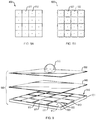
- FIGS. 8A and 8B each illustrate an array of electrodes employed for EWOD.
- the electrodes In FIG. 8A , the electrodes have straight edges. In FIG. 8B , the electrodes have serrated edges.
- FIG. 9 shows an exploded view of an EWOD plate and a droplet resting on it.
- FIGS. 10A, 10B and 10C show a droplet changing shape.
- FIGS. 10D, 10E and 10F show droplets merging and their contents mixing.
- FIGS. 11A, 11B, 11C, and 11D show droplets shifting position in a 1D “shift register”.
- FIGS. 12A, 12B, and 12C show droplets shifting position in a 2D “shift register”.
- FIGS. 13A, 13B, 13C, and 13D show droplets being mixed, before being moved into position on an EWOD plate.
- FIG. 14 shows droplets being moved into position under an EWOD plate and then deposited to form a 3D object.
- FIG. 15 illustrates moving an EWOD plate.
- FIGS. 16A and 16B show movement of a droplet that is beneath, and touching, an EWOD plate.
- FIGS. 17 and 18 each show a system for controlling droplets and capacitively sensing their positions.
- FIG. 19 shows a fabrication system that includes an EWOD plate.
- FIGS. 20 and 21 each show a fabrication system that includes a robotic arm that moves an EWOD plate.
- FIGS. 22A, 22B and 22C show vertical movement of a droplet.
- EWOD electrowetting-on-dielectric
- a computer controls voltage in an array of electrodes in an EWOD plate and thereby controls electric fields created by the electrodes.
- the EWOD plate By varying these electric fields, the EWOD plate repeatedly changes the shape of droplets and moves droplets across a surface.
- This EWOD technique enables a set of primitive operations, such as precisely translating, morphing, merging, and splitting multiple droplets simultaneously. These primitive operations may, in turn, be employed to mix materials in different droplets and to organize droplets in a layer before depositing the layer on a 3D object being fabricated.
- a dielectric layer may be located between the electrodes and the droplet; and (b) in many cases, a hydrophobic layer may be located between the dielectric layer and the droplet. Alternatively, in some cases, the dielectric layer itself is strongly hydrophobic and a separate hydrophobic layer is not employed.
- an EWOD plate includes (from bottom to top) a substrate, an array of electrodes, a dielectric layer and a hydrophobic layer; (b) a droplet is on top of, and touching, the hydrophobic layer; and (c) the droplet is located directly above only one specific electrode in an array of electrodes in the EWOD plate and is not directly over other electrodes in the array.
- the droplet may tend to be repelled by the hydrophobic surface and may tend to be rounder, and the contact angle (between the droplet and the hydrophobic surface) may be large.
- the droplet may “wet in”, causing the droplet to flatten and causing the contact angle to become smaller. If the positive voltage is then turned off (so that all of the electrodes in the array are grounded), then: (a) the droplet may again become rounder due to being repelled by the hydrophobic layer; and (b) the contact angle may increase.
- a sufficiently strong electric field may cause a single droplet to spread across an entire electrode.
- the electric field may be created by applying a positive voltage to the electrode, and by causing neighboring electrodes (or other neighboring nodes) to have a lower voltage (e.g., to be grounded). Applying a positive voltage to multiple electrodes may cause a single droplet to be stretched across them. Removing the positive voltage may cause a droplet to become rounder (more pushed out from a hydrophobic surface) and to cover less electrodes. By controlling spreading of a droplet, the shape of a droplet may be controlled.
- FIG. 1 shows a droplet on an EWOD plate, in an illustrative implementation of this invention.
- EWOD plate 101 includes an array of square electrodes (e.g., electrodes 103 , 105 ).
- the electrodes e.g., 103 , 105
- each have serrated edges e.g., 107 , 109 ).
- EWOD plate 101 is configured to move droplets by changing voltages of the electrodes.
- FIG. 1 shows droplet 100 at a time when droplet 100 is located above four electrodes and is primarily located over a single electrode.
- FIGS. 2A and 2B illustrate movement of a droplet in response to a change in electric potential, in an illustrative implementation of this invention.
- FIGS. 2A and 2B show a temporal sequence, with FIGS. 2A and 2B being the first and the last, respectively, in the sequence.
- droplet 206 is located above EWOD plate 200 .
- the EWOD plate 200 includes a substrate layer 204 , electrode layer 203 , dielectric layer 202 and hydrophobic layer 201 .
- Droplet 206 is touching hydrophobic layer 201 .
- electrodes 211 , 212 , 213 are each connected to ground, and no voltage is being applied to droplet 206 .
- droplet 206 contacts EWOD plate 200 at contact angle ⁇ .
- electrodes 211 and 213 are each connected to ground.
- electrode 212 has a positive voltage, relative to electrodes 211 and 213 .
- droplet 206 contacts EWOD plate 200 at contact angle ⁇ .
- FIG. 2B shows droplet 206 in an equilibrium state after the positive voltage has been applied to electrode 212 .
- the positive voltage at electrode 212 has caused droplet 206 to move (from its position shown in FIG. 2A ) to a new position in which the droplet is centered over electrode 212 .
- this applied positive voltage has changed the shape of droplet 206 , by causing droplet 206 to have a contact angle of ⁇ , where ⁇ > ⁇ . In other words, the positive voltage causes the contact angle to be less steep (than it would be in the absence of the positive voltage).
- FIGS. 3A and 3B illustrate movement of a droplet in response to a change in electric potential.
- FIGS. 3A and 3B show a temporal sequence, with FIG. 3A being the first in the sequence.
- the droplet is below an EWOD plate.
- the EWOD plate 300 includes a substrate layer 304 , electrode layer 303 , dielectric layer 302 and hydrophobic layer 301 .
- Droplet 306 is touching hydrophobic layer 301 .
- droplet 306 is centered under electrode 312 , which has a positive voltage relative to electrodes 311 , 313 and 314 .
- electrodes 311 , 313 and 314 are each connected to ground.
- FIG. 3B shows droplet 306 after it has moved to a new position, in response to a change in voltage. Specifically: (a) electrode 312 had a positive voltage in FIG. 3A and is grounded in FIG. 3B ; and (b) electrode 313 was grounded in FIG. 3A and has a positive voltage in FIG. 3B . In FIG. 3B , droplet 306 has moved so that it is now centered under electrode 313 . In FIGS. 3A and 3B , droplet 306 is in equilibrium.
- the hydrophilic layer (e.g., 201 , 301 , 1601 , 2001 ) may comprise a smooth surface.
- the droplet (e.g., 206 , 306 , 1615 ) may contain small particles (e.g., 215 , 315 ), such as cells, cellular fragments, nucleic acids, proteins or molecules (e.g., molecules involved in a polymerase chain reaction or in a chemical reaction).
- the droplet (e.g., 206 , 306 , 1615 ): (a) may comprise a solution, colloidal suspension, emulsion or mixture; and (b) may include solutes, colloids, suspended matter (e.g., cells or tissue), or immiscible fluids.
- FIGS. 4A, 4B and 4C illustrate an effect of an electric field on a droplet.
- FIGS. 4A-4C show a temporal sequence, with FIGS. 4A and 4C being the first and the last, respectively, in the sequence.
- FIG. 4A shows a droplet 408 before a positive voltage is applied to electrode 402 .
- FIG. 4B shows droplet 408 immediately after a positive voltage is applied to electrode 402 .
- droplet 408 is not in equilibrium.
- FIG. 4C shows droplet 408 in equilibrium, after the positive voltage is applied to electrode 402 .
- two electrodes that differ in voltage may create an electric field that acts at a distance, causing a droplet to move toward the more positive electrode.
- the difference in voltage between the positive electrode 402 and the grounded electrodes 401 , 403 creates an electric field (symbolized by electric field lines 411 , 412 ).
- This electric field causes droplet 408 to move from a first position in FIG. 4A (where droplet 408 is centered above grounded electrode 401 ) to a second position in FIG. 4C (where droplet 408 is centered above positive electrode 402 ).
- FIG. 4A where droplet 408 is centered above grounded electrode 401
- FIG. 4C where droplet 408 is centered above positive electrode 402 .
- the electric field changes surface tensions in the droplet in such a way as to create a net force that includes a component that is parallel to surface 404 and that pushes droplet 408 laterally nearer to electrode 402 .
- This net force occurs in FIG. 4B even though droplet 408 is not, at the time, touching the portion of surface 404 that is immediately above positive electrode 402 .
- Drop 408 is flatter (less round) in FIG. 4C than in FIG. 4A . This is because of the positive voltage applied to electrode 402 in FIG. 4C .
- Electrodes 401 and 403 are grounded in FIGS. 4A-4C .
- Electrode 402 is grounded in FIG. 4A and has a positive voltage in FIGS. 4B and 4C .
- FIGS. 5A, 5B and 5C illustrate translation of a droplet.
- the change in location of the positive electrode(s) in these Figures causes droplet 508 to translate laterally across surface 504 .
- FIGS. 5A-5C show a temporal sequence, with FIGS. 5A and 5C being the first and the last, respectively, in the sequence.
- electrode 501 has a positive voltage and electrodes 502 , 503 are grounded. This causes droplet 508 to be centered over electrode 501 .
- electrodes 501 and 502 have a positive voltage and electrode 503 is grounded. This causes droplet 508 to spread out and to be centered between electrodes 501 and 502 .
- electrode 502 has a positive voltage and electrodes 501 and 503 are grounded. This causes droplet 508 to be centered above electrode 502 .
- FIGS. 6A, 6B and 6C illustrate merging two droplets. This merging is actuated by changes in voltage of electrodes.
- FIGS. 6A-6C show a temporal sequence, with FIGS. 6A and 6C being the first and the last, respectively, in the sequence.
- electrodes 601 and 603 have a positive voltage and electrode 602 is grounded. This causes droplets 607 and 609 to be centered over electrodes 601 and 603 , respectively.
- electrodes 601 , 602 and 603 have a positive voltage and other nearby electrodes (not shown) are grounded. In FIG. 6B , this has caused droplets 607 and 609 to spread out and merge, thereby forming a larger droplet 608 .
- electrode 602 has a positive voltage and electrodes 601 and 603 are grounded. This causes droplet 608 to be centered above electrode 602 .
- a droplet may be split into two smaller ones through a sequence of voltages, applied across multiple electrodes (e.g., at least three) as in FIG. 7B . To do so, a single droplet may be spread across three adjacent electrodes by applying equal voltage to all of them simultaneously. Then the center electrode may be “turned off” (e.g., grounded) thereby causing the droplet to move away from the center electrode. Due to the equal voltage at both neighboring electrodes, the droplet may then split into two smaller droplets.
- FIGS. 7A, 7B and 7C illustrate splitting a larger droplet into two smaller droplets. This splitting is actuated by changes in voltage of electrodes.
- FIGS. 7A-7C show a temporal sequence, with FIGS. 7A and 7C being the first and the last, respectively, in the sequence.
- electrode 702 has a positive voltage and electrodes 701 and 703 are grounded. This causes droplet 708 to be centered above electrode 702 .
- electrodes 701 , 702 and 703 have a positive voltage and other nearby electrodes (not shown) are grounded. In FIG. 7B , this has caused droplet 708 to spread out to cover electrodes 701 , 702 and 703 .
- electrodes 701 and 703 have a positive voltage and electrode 702 is grounded. This has caused droplet 708 to split into smaller droplets 707 and 709 , which are centered over electrodes 701 and 703 , respectively.
- each droplet (a) is in equilibrium; and (b) rests on a surface.
- This surface e.g., 404 , 504 , 604 , 704
- the hydrophobic layer may be between the dielectric layer and the droplet.
- the surface e.g., 404 , 504 , 604 , 704
- FIGS. 8A and 8B each illustrate an array of electrodes employed for EWOD.
- the electrodes (e.g., 811 , 812 ) in array 800 have straight edges.
- the electrodes (e.g., 821 , 822 ) in array 820 have serrated edges.
- serrations at the edges of the electrodes may create overlapping electrical fields that facilitate actuation and control of a droplet.
- the overlapping fields may result in an electric field gradient that generates a force to propel a droplet when voltages in the electrodes are modulated.
- the size of the electrodes may vary.
- the electrodes may be millimeter-scale.
- the electrodes (and gaps between them) may be micron-scale.
- the electrode size may affect the minimum droplet size and the level of control. A finer granularity of electrode may provide a higher resolution for the electric field and may make a seamless transition of droplets possible, but also may result in more complex PCBs (printed circuit boards) and driving circuits.
- the electrodes may comprise any type of conductive material, including metal or metal alloy.
- the electrodes comprise a transparent material (e.g., indium tin oxide).
- the electrodes are flexible, including a flexible composite material.
- the electrodes may comprise any flexible Pyralux® material, including copper-clad laminate, polymide single sided copper clad laminate, polymide double sided copper clad laminate, or acrylic-based copper clad laminate.
- FIG. 9 shows an exploded view of an EWOD plate and a droplet resting on it.
- EWOD plate 900 comprises a substrate 901 , an electrode array 910 , a dielectric layer 940 , and a hydrophobic layer 950 .
- Electrode array 910 includes multiple electrodes (e.g. electrodes 911 , 912 , 913 ). Changes in voltage in the electrodes in array 910 create electric fields that cause different regions of plate 900 to be more or less hydrophilic and actuate movement of droplets (e.g., droplet 960 ) on plate 900 .
- the substrate layer (e.g., 204 , 304 , 901 ) may be rigid or flexible, transparent or opaque.
- the substrate layer (e.g., 204 , 304 , 901 ) comprises glass, polyethylene terephthalate (PET), a thermoplastic polymer, Kapton® (that is, poly (4,4′-oxydiphenylene-pyromellitimide)), or FR4.
- the FR4 material may comprise a material (such as a copper-clad laminate, a glass epoxy, or a glass-reinforced epoxy laminate) that complies with the FR-4 grade as defined by the NEMA LI 1-1998 specification.
- FR4 may provide a rigid, non-transparent, and flat interaction surface.
- the dielectric layer (e.g., 202 , 302 , 940 ) comprises low-density polyethylene, polyvinylidene chloride, Saran WrapTM, plastic paraffin, Parafilm® (e.g., Parafilm M), polydimethylsiloxane (PDMS), polytetrafluoroethylene (PTFE), perfluoroalkoxy alkane (PFA), fluorinated ethylene propylene (FEP), polyp-xylylene) polymers (e.g., Parylene® or Parylene® C), Teflon®, or plastic.
- Parafilm® e.g., Parafilm M
- PDMS polydimethylsiloxane
- PTFE polytetrafluoroethylene
- PFA perfluoroalkoxy alkane
- FEP fluorinated ethylene propylene
- polyp-xylylene polymers e.g., Parylene® or Parylene® C
- Teflon® or plastic
- the dielectric material e.g., Teflon®
- the dielectric material is itself hydrophobic.
- a separate hydrophobic layer e.g., silicone oil
- a separate hydrophobic layer e.g., silicone oil
- hydrophobic materials may be employed, in illustrative implementations of this invention.
- the hydrophobic layer e.g., 201 , 301 , 950
- the hydrophobic layer may comprise: (a) oil (e.g., silicone oil), Teflon®, or Teflon® AF amorphous fluoroplastic; or (b) a self-assembled monolayer (SAM) with low surface energy.
- oil e.g., silicone oil
- Teflon® Teflon® AF amorphous fluoroplastic
- SAM self-assembled monolayer
- one or more of the layers (e.g., substrate, electrode layer, dielectric layer or hydrophobic layer) of an EWOD plate are fabricated by conventional methods of fabricating a PCB (printed circuit board) or IC (integrated circuit).
- a PCB printed circuit board
- IC integrated circuit
- one or more of the following methods may be employed to fabricate all or part of an EWOD plate (including the substrate, electrodes, dielectric layer, hydrophobic layer, and conductive routing): vapor deposition, spraying, dip-coating, spin coating, photolithography, masking, etching, cleaning, and doping.
- a copper-clad PCB may be laser-cut.
- an EWOD plate is fabricated with multi-layer routing. The multi-layer routing may facilitate applying voltages to separately addressable electrodes in a large 2D grid and may also facilitate capacitive sensing.
- an electric field is created between two regions of an EWOD plate, that are nearby each other and that have different voltages. In many cases, this difference in voltage is achieved by applying a positive voltage to a first electrode and grounding a nearby electrical node.
- each electrode e.g., 911 , 912 , 913
- an EWOD plate e.g., 900
- the electrode in one state of the switch, the electrode is grounded; and (b) in another state of the switch, the electrode has, at least at some times, a positive or negative voltage.
- an additional electric node e.g. 921 , 922 , 931 , 932
- these additional nodes are (at least at some times) grounded.
- an additional node is located in the horizontal interior of each electrode.
- an additional electric node e.g., 921
- an additional electric node may be located at or near the horizontal center of—and may be electrically insulated from—an electrode (e.g., 911 ); and (b) this additional electric node (e.g., 921 ) may be (at least at some times) grounded.
- the additional nodes are located between the electrodes.
- additional node 931 may be located between—and may be electrically insulated from—electrodes 911 and 912 ;
- additional node 932 may be located between—and may be electrically insulated from—electrodes 912 and 913 ; and
- the additional nodes e.g., 931 , 932 ) may be (at least at some times) grounded.
- FIGS. 10A, 10B and 10C show a droplet changing shape.
- FIG. 10A-10C show a temporal sequence; FIGS. 10A and 10C being the first and last, respectively, in the sequence.
- Drop 1001 is more rounded in FIG. 10A , then flattens in FIG. 10B , then becomes more rounded again in FIG. 10C .
- droplet 1001 is centered over electrode 1020 and touches other electrodes (e.g., 1030 ).
- droplet 1001 is located primarily over electrodes 1020 and 1030 .
- droplet 1001 is centered over electrode 1030 and touches other electrodes (e.g., 1020 ).
- the changes in shape and lateral translation of droplet 1001 that are described in this paragraph may be actuated by changes in voltage applied to the electrodes. Specifically: (a) in FIG.
- electrode 1020 may have a positive voltage and surrounding electrodes may be grounded; (b) in FIG. 10B , electrodes 1020 and 1030 may have a positive voltage and surrounding electrodes may be grounded; and (c) in FIG. 10C , electrode 1030 may have a positive voltage and surrounding electrodes may be grounded.
- rapid switching of electrodes results in oscillating behavior of droplets. For instance, a sequence of voltage changes may be repeated to cause rapid oscillation in the shape of a droplet. In some cases, the rapid oscillation speeds the mixing of contents of a recently merged droplet.
- FIGS. 10D, 10E and 10F show droplets merging and their contents mixing.
- FIGS. 10D-10F show a temporal sequence; FIGS. 10D and 10F being the first and last, respectively, in the sequence.
- droplets 1002 and 1003 are separate.
- the material composition of droplet 1002 is different than that of droplet 1003 .
- droplet 1002 may contain a different solution, solute, colloid, colloidal suspension, emulsion, mixture, suspended matter (e.g., cells or tissue), or immiscible fluids than does droplet 1003 .
- FIG. 10E positive voltage has been applied to electrode 1030 .
- this positive voltage has caused droplets 1002 and 1003 to merge into droplet 1004 and caused droplet 1040 to be centered over electrode 1030 .
- droplets 1002 and 1003 have only recently merged to form droplet 1004 and the contents of droplet 1004 have not yet fully mixed.
- the droplets ( 1001 , 1002 , 1003 , 1004 ) are on top an EWOD plate 1000 that includes an array of electrodes. Changing the relative voltages applied to different electrodes in the array creates a time-varying electric field that causes droplets located on the EWOD plate to move, merge or split.
- one or more EWOD plates are employed to fabricate 3D multi-material structures.
- the one or more EWOD plates may control the movement, mixing, and deposition of droplets in such a way that the plates deposit layers of droplets to assemble the 3D multi-material structures.
- an EWOD plate (a) may cause droplets to move in such a way that the droplets become precisely organized on a planar surface of the plate; and (b) may alter an electric field to cause the droplets to be simultaneously deposited as a single layer.
- a 3D object may be fabricated.
- the 3D object that is created may be entirely solid or may comprise different materials in different physical states (e.g., may include both solid and liquid materials).
- the droplets include suspended particles that at least partially form the 3D object.
- the droplets may contain one or more materials that trigger or undergo a chemical reaction. For example, at least a portion of the materials in the droplets may cure or otherwise solidify after the droplets are deposited.
- a “parallel” assembly process For fabrication of a 3D structure, a “parallel” assembly process may be employed.
- droplets may be simultaneously organized on multiple EWOD plates. While droplets are being deposited by one EWOD plate, droplets may be being organized on other EWOD plates. After droplets on a given EWOD plate are organized in a desired pattern on the plate, the droplets from that plate may be deposited (on the object being fabricated) and the process of organizing droplets on that plate may begin again.
- This “parallel” assembly process may greatly increase the rate at which droplets are deposited to fabricate a 3D object.
- an EWOD plate may be configured to handle a wide range of sizes of droplets.
- the size of droplets that are touching, and actuated by, an EWOD plate may be from 20 ⁇ l to 1 ml, including droplets that are 20 mm ⁇ 20 mm in their x and y dimensions.
- the size of the droplets is in the picoliter range; and (b) the size of 3D structures that are fabricated by the droplets is extremely small (e.g., in the nanometer, micron or millimeter range
- a wide variety of materials and particles may be contained (e.g., in a dissolved, suspended or emulsified state) in the droplets or may be created by chemical reactions that occur when droplets are mixed.
- a wide variety of types of 3D objects may be created by depositing droplets from one or more EWOD plates.
- deposition of droplets from EWOD plates may be employed to fabricate electronics, mechanical structures (e.g., trusses, cellular lattices, meta-materials), or biological materials (e.g., tissues, DNA), to name a few.
- deposition of droplets from one or more EWOD plates may fabricate (e.g., at the micron scale) fully-functional electromechanical components.
- each of the EWOD plates employed for the deposition of droplets comprises electrodes on a single plane with no cover plate. This “open” configuration may facilitate simultaneously adding—or simultaneously removing—a large number of droplets to or from an EWOD plate.
- the EWOD plates transport, merge and split droplets with great precision. This in turn enables mixing of different materials for variable material properties and geometry, and thus allows precise control of the droplets being deposited.
- the EWOD plates may regulate volume of droplets by precisely splitting or merging droplets.
- the EWOD plates achieve high-speed manipulation of droplets, thereby enabling rapid deposition of droplets to fabricate a 3D object.
- an EWOD plate transports macro-scale droplets at 200 mm/s.
- an inverted EWOD plate (with a hydrophilic layer at the bottom of the plate) may transport small droplets at high speed while the droplets are touching the bottom of the plate and are being pressed against the bottom of the plate due to the electric field.
- micro-scale objects may be picked up and dropped through capillary force enabled droplet grippers. These grippers may pick up prefabricated blocks such as trusses, and micro-electronics.
- the EWOD plates are configured to transport droplets linearly along a single column or row of electrodes.
- the electrowetting platform is organized to transport droplets linearly on an electrode array.
- the manner in which droplets are loaded onto or under a single column or row of electrodes may resemble, by rough analogy, the manner in which data bits are serially loaded onto a shift register.
- An example of this “shift register” loading is shown in FIGS. 11A-11D .
- an EWOD plate may include an array of columns and rows of electrodes; and (b) droplets may be simultaneously loaded onto (or under) multiple rows (or multiple columns) of electrodes in the array.
- the manner in which droplets are loaded onto or under multiple rows (or multiple columns) of the array at the same time may resemble, by rough analogy, the manner in which data bits may be loaded in parallel unto a 2D register array.
- An example of this “register array” loading is shown in FIGS. 12A-12C .
- a computer may control the geometry and composition of each voxel making up the 3D object being fabricated; and (b) may (by controlling electric fields created by electrodes) cause droplets made of different materials to be deposited next to each other or mixed before deposition. For instance, the droplets may be mixed before deposition as shown in FIGS. 13A-13D .
- a single EWOD plate is positioned over a build platform; (b) the EWOD plate does not move horizontally relative to the build platform while the 3D object is being fabricated.
- the EWOD plate may create electric fields that actuate the movement, merging or splitting of droplets; (b) this movement of droplets may occur while the droplets are under and touching the bottom side of the EWOD plate (due to the electric fields causing the droplets to press up against the bottom of the plate); (c) this movement of droplets may result in the droplets being organized in a single layer while touching the bottom side of the plate; and (d) the EWOD plate may then turn off (or otherwise alter) the electric fields in such a way that the droplets are released (from the plate) as a single layer and are deposited on the 3D object being fabricated.
- the EWOD plate may repeat the process described in the preceding sentence multiple times to organize and deposit multiple layers of droplets, one layer at a time, during fabrication of the 3D object. Examples of this approach are shown in FIGS. 14 and 19 .
- droplets may be moved simultaneously along multiple rows or multiple columns of electrodes while touching the bottom of the plate.
- a “Droplet Assembler Robot” may organize a layer of droplets on or under each of two or more EWOD plates, respectively. Then a “Pick and Place Robot” may, for each of the EWOD plates, respectively, move the plate to a position over the build platform, where the layer of droplets may be released.
- the Droplet Assembler Robot (a) may employ EWOD actuation to transport droplets from raw feedstock to each of the two or more EWOD plates, respectively; and (b) may organize the droplets as a layer on or under each of two or more EWOD plates, respectively.
- the Pick and Place Robot may then pick up one of the EWOD plates (while the layer of droplets is still touching the plate), move it into position over the build platform, and release the layer of droplets. After droplets are released from a given EWOD plate, the Pick and Place Robot may move that plate back to a position in which the Droplet Assembler Robot may load droplets unto or under the plate. These actions by the Pick and Place Robot (which are described in the preceding two sentences) may be repeated for each of the EWOD plates each time that droplets are organized on or under the plate. Repetition of the process described in this paragraph enables rapid, layer-by-layer deposition of droplets. An example of this approach is shown in FIG. 20 (and a similar approach is shown in FIG. 15 ).
- a Droplet Assembler Robot may assemble a layer of droplets that is touching the bottom of an EWOD plate; and (b) a Pick and Place Robot may, without turning the plate over, move the plate to a position where the layer of droplets is released.
- the Droplet Assembler Robot organizes the droplets on top of (instead of under) the EWOD plate.
- the Pick and Place Robot may, before the droplets are released from the plate, turn the plate over, in such a way that: (a) the top layer of the plate becomes the bottom layer of the plate; and (b) the layer of droplets that are touching the top surface of the plate are, after the plate is turned over, touching the bottom of the plate instead.
- Electric fields created by electrodes in the EWOD plate may cause the layer of droplets to continue to touch the plate while the plate is being turned over and after the plate has been turned over, until the layer of droplets is released from the plate.
- multiple Droplet Assembler Robots and multiple Pick and Place Robots operate in parallel and thereby speed up the assembly process.
- the material in droplets organized by the Droplet Assembler Robot is processed before being deposited by the Pick and Place Robot.
- the material may be partially bonded or glued together to form a single layer before deposition.
- the droplets are not in physical contact with the top layer of the 3D object; and (b) thus the droplets fall at least a short distance from the EWOD plate before touching the top layer of the 3D object being fabricated.
- the distance between the EWOD plate and build platform is reduced (by lowering the EWOD plate or raising the build platform) until the layer of droplets (which are still touching the EWOD plate) comes into physical contact with the top layer of the object being fabricated; (b) then the layer of droplets is released from the plate (e.g., by turning off or otherwise altering electric fields that were holding the droplets up against the bottom of the plate); and (c) then the distance between the EWOD plate and build platform is increased (by raising the EWOD plate or lowering the build platform) until the EWOD plate is no longer in contact with the layer of droplets.
- FIGS. 11A, 11B, 11C, and 11D show droplets shifting position in a 1D “shift register”.
- FIGS. 11A-11D are in temporal sequence; FIGS. 11A and 11D being the first and last, respectively, in the sequence.
- the droplets move in a single direction 1110 in single file along a single path (e.g., a column of electrodes) 1120 for a period of time.
- the droplets are actuated to shift position by changing voltage applied to the electrodes.
- the droplets are sufficiently small so that each droplet covers only one electrode, as shown in FIGS. 11A-11D .
- the droplets may be actuated to move forward, one droplet at a time, in a temporal sequence, in a manner loosely analogous to a “shift register”. For example, in FIG.
- droplets 1101 , 1102 , 1103 may be actuated to move forward as follows: (a) first, make electrode 1130 more positive than electrode 1131 , thereby causing droplet 1101 to move from electrode 1131 to electrode 1130 ; (b) second, make electrode 1131 more positive than electrode 1132 , thereby causing droplet 1102 to move from electrode 1132 to electrode 1131 ; and (c) third, make electrode 1132 more positive than electrode 1133 , thereby causing droplet 1103 to move from electrode 1133 to electrode 1132 .
- a first electrode may be made more positive than a second electrode by applying a positive voltage to the first and grounding the second.
- each droplet covers multiple electrodes (and the droplets maintain sufficient distance, center-to-center, to remain separate).
- the droplets may be actuated to move forward, one droplet at a time, in a temporal sequence, in a manner loosely analogous to a “shift register”.
- the “leader” droplet in the front of the single file
- the “leader” droplet may be caused to move forward by applying (to an electrode that is in front of the leader droplet or that touches the front of the leader droplet), a voltage that is more positive than the voltage of electrodes underneath the center and rear of the leader droplet.
- the next droplet in the single file may be actuated to move forward in a similar manner.
- all the droplets in the single file may move forward, one droplet at a time, in a temporal sequence.
- a first electrode may be made more positive than a second electrode by applying a positive voltage to the first and grounding the second.
- FIGS. 12A, 12B, and 12C show droplets shifting position in a 2D “shift register” or “shift array”.
- FIGS. 12A-12C are in temporal sequence; FIGS. 12A and 12C being the first and last, respectively, in the sequence.
- rows of droplets (e.g., rows 1201 , 1202 , 1203 , 1204 , 1205 , 1206 , 1207 , 1208 ) move in a single direction 1210 across an EWOD plate 1220 that includes a 2D array of electrodes.
- the droplets are actuated to shift forward by changing voltage applied to the electrodes.
- the droplets are sufficiently small that each droplet covers all or part of only one electrode, as shown in FIGS. 12A-12C .
- rows of droplets may be actuated to move forward, one row of droplets at a time, in a temporal sequence, in a manner loosely analogous to a 2D “shift register”. For example, in FIG.
- droplet rows 1201 , 1202 , 1203 may be actuated to move forward as follows: (a) first, make electrode row 1230 more positive than electrode row 1231 , thereby causing a first row of droplets 1201 to move from electrode row 1231 to electrode row 1230 ; (b) second, make electrode row 1231 more positive than electrode row 1232 , thereby causing a second row of droplets 1202 to move from electrode row 1232 to electrode row 1231 ; and (c) third, make electrode row 1232 more positive than electrode row 1233 , thereby causing a third row of droplets 1203 to move from electrode row 1233 to electrode row 1232 .
- a first electrode row may be made more positive than a second electrode row by applying a positive voltage to the first and grounding the second.
- a 2D “shift register” may be implemented where each droplet covers multiple electrodes (and the droplets maintain sufficient distance, center-to-center, to remain separate).
- rows of droplets may be actuated to move forward, one row of droplets at a time, in a temporal sequence, in a manner loosely analogous to a 2D “shift register”. For instance, by turning rows of electrodes positive, one row of electrodes at a time, rows of droplets may be actuated to move forward, one row of droplets at a time.
- FIGS. 13A, 13B, 13C, and 13D show droplets being mixed, before being moved into position on an EWOD plate.
- FIGS. 13A-13D are in temporal sequence, with FIGS. 13A and 13D being the first and last, respectively, in the sequence.
- paths 1305 , 1307 , 1405 , 1407 , 1470 , 1471 are each, respectively, a narrow EWOD plate that comprises a substrate, electrode layer, dielectric layer and hydrophobic layer; and (b) likewise, plates 1310 , 1410 are each, respectively, an EWOD plate that comprises a substrate, electrode layer, dielectric layer and hydrophobic layer.
- Paths 1307 , 1405 , 1407 , 1470 , 1471 are narrow: they each include only a single row or column of electrodes or only a single bent line of electrodes.
- plates 1310 , 1410 each include a 2D array of electrodes, including multiple rows and columns of electrodes.
- droplet 1301 is centered above electrode 1331 on path 1305 ; and (b) droplet 1303 is centered above electrode 1333 on path 1307 .
- droplet 1301 has been moved so that droplet 1301 is centered above electrode 1332 .
- droplet 1303 has been moved so that droplet 1303 is centered above electrode 1334 .
- droplets 1301 and 1303 have merged to form droplet 1304 .
- Droplet 1304 may then be moved into position on plate 1310 .
- FIG. 14 shows droplets being moved into position under an EWOD plate and then deposited to form a 3D object.
- the droplets are being moved directly or indirectly toward plate 1410 .
- droplets 1421 and 1422 are being moved along path 1407 toward electrode 1460 , and then may be moved along path 1405 toward plate 1410 .
- droplets 1411 , 1412 , 1423 are being moved along path 1405 toward plate 1410 .
- droplets 1421 , 1422 , 1423 may be from a first reservoir and may comprise a first material; and (b) droplets 1411 , 1412 may be from a second reservoir and may comprise a second material.
- droplets e.g., 1411 , 1412 , 1421 , 1422 , 1423 , 1430
- an EWOD plate e.g., 1405 , 1407 , 1410
- paths 1405 , 1407 are narrow EWOD plates.
- positive voltages in one or more electrodes in EWOD plate 1410 may be turned off (e.g., by grounding). This in turn may cause a group of droplets (which touch the bottom of plate 1410 at the moment of time shown in FIG. 14 ) to be released from the plate and to be deposited on 3D object 1440 .
- a group of droplets which touch the bottom of plate 1410 at the moment of time shown in FIG. 14
- the electrodes in plate 1410 may be grounded simultaneously; and (b) the group of droplets that are released may comprise all or some of the droplets 1430 that are underneath (and touching the bottom surface of) plate 1410 in FIG. 14 .
- the released droplets may comprise all of the droplets that are (immediately before the release) underneath and touching the plate and may comprise a single layer of droplets.
- the droplets may—while they are still touching the plate and immediately before being released from the plate—also be touching 3D object 1440 that is being fabricated. Or the droplets may, after being released, fall a short distance before physically contacting 3D object 1440 .
- a 3D object ( 1440 ) comprises layers (e.g., 1451 , 1452 , 1453 ) formed by deposition of droplets.
- the layers in 3D object 1440 may be a material (e.g., a composite material) that includes one or more of the following: (a) polymers; (b) cells or cell fragments; (c) tissue; (d) single-cell or multi-cell organisms, including bacteria or fungi; (e) viruses; (f) chemokines; (g) hydrogel (e.g., PV-based gels; (h) alginate, (i) biomaterial; (j) bioactive or bioengineered material; (k) nutrients; (l) matrix material; (m) scaffold material; (n) resin; (o) curing agent; or (p) any inorganic, organic or bioactive material.
- the materials in object 1440 may be included in the deposited droplets, or may be produced by chemical or biochemical reactions that involve materials that
- droplets may solidify or cure after (or while or before) being deposited by an EWOD plate.
- the droplets may include a photopolymer that is cured by exposure to light (e.g., ultraviolet light) after being released from an EWOD plate (e.g., 1410 , 1761 , 2063 ).
- light e.g., ultraviolet light
- UV light may cure the photopolymer after the droplets have been deposited on a build platform (e.g., 1490 , 1780 , 2080 ) or on a 3D object (e.g., 1440 ) being fabricated on a build platform.
- the droplets may include a resin (e.g., a thermosetting resin) and a curing agent that causes the resin to polymerize.
- the resin and curing agent may be in separate droplets that mix after leaving an EWOD plate (e.g., 1410 , 1761 , 2063 ).
- the resin and curing agent may mix while or after impacting a build platform (e.g., 1490 , 1780 , 2080 ) or while or after impacting a 3D object (e.g., 1440 ) being fabricated on the build platform.
- the resin and curing agent may be mixed by merging droplets while they are touching an EWOD plate, and the merged droplets may then be quickly released from the plate.
- the resin may comprise polyurethane resin, epoxy resin, polyester resin, unsaturated polyester resin, acrylic resin or silicone resin.
- the polymerization of the resin may occur at room temperature and normal pressure (e.g., at a standard atmosphere of pressure).
- the curing agent may comprise a source of free radicals that initiates a free-radical chemical chain reaction polymerization.
- the curing agent may comprise a polymer and the product that results from curing may comprise a copolymer.
- FIG. 15 illustrates moving an EWOD plate.
- droplets are moved into position on top of an EWOD plate. Then, the plate: (a) is moved to a new position over a build platform; and (b) is turned over, so that the droplets are underneath (and touching) the EWOD plate. Then the droplets are released from the EWOD plate (e.g., by grounding electrodes in the plate). The released droplets are deposited on a build platform (or on a 3D object that is being fabricated on the build platform).
- droplets 1430 may be held substantially stationary relative to EWOD plate 1410 : (a) while plate 1410 is being turned over; and (b) for a period of time after plate 1410 is turned over.
- This may be achieved by applying positive voltage to one or more electrodes that are near the droplet. For instance, a droplet may be centered over (or under) an electrode, and a positive voltage may be applied to the electrode.
- EWOD plate 1410 is initially located at position 1491 . While EWOD plate 1410 is located at position 1491 , droplets 1430 are moved (by EWOD actuation) onto plate 1410 via paths 1470 , 1471 and arranged in rows and columns on top of EWOD plate 1410 . For instance, droplets that are transported to plate 1410 via paths 1470 and 1471 may be from a first reservoir and a second reservoir, respectively, and may contain different materials.
- EWOD plate 1410 is then moved into a new position 1492 that is above build platform 1490 .
- this movement 1480 of plate 1410 may include a translation that includes both vertical and horizontal components; and (b) may also involve turning plate 1410 over (while droplets 1430 continue to touch plate 1410 and remain in substantially the same position relative to plate 1430 ).
- FIG. 15 (a) a top surface of plate 1410 before the plate is turned over becomes a bottom surface of plate 1410 after the plate is turned over; and (b) droplets 1430 are on top of (and touching) plate 1410 when it is in position 1491 and then are below (and touching) plate 1410 when it is in position 1492 .
- droplets 1430 are below (and touching) plate 1410 while it is in both positions 1491 and 1492 ; and (b) movement 1480 of plate 1410 does not involve turning over plate 1410 .
- paths 1470 , 1471 remain stationary.
- paths 1470 and 471 may (during movement 1480 ) remain stationary relative to object 1440 and relative to build platform 1490 .
- paths 1470 and 1471 move together with plate 1410 during movement 1480 .
- paths 1470 and 1471 may remain stationary relative to plate 1410 during movement 1480 .
- actuator 1483 actuates movement 1480 of plate 1410 .
- actuator 1483 comprises a robot.
- EWOD plate 1410 after EWOD plate 1410 is in position 1492 : (a) electrodes in plate 1410 may be grounded; and (b) then droplets that are beneath (and touching) plate 1410 may fall (e.g., due to gravity) in a downward direction, away from plate 1410 and toward build platform 1490 . Alternately, the droplets may, when they are released, already be touching 3D object 1440 . In either case, the released droplets may be deposited: (a) on build platform 1490 ; or (b) on 3D object 1440 which is being fabricated on build platform 1490 .
- FIGS. 16A and 16B show movement of a droplet that is beneath, and touching, an EWOD plate.
- droplet 1615 is below an EWOD plate 1600 .
- the EWOD plate 1600 includes a substrate layer 1604 , electrode layer 1603 , dielectric layer 1602 and hydrophobic layer 1601 .
- droplet 1615 is touching hydrophobic layer 1601 .
- droplet 1615 is centered under electrode 1611 (which has a positive voltage).
- electrode 1611 which has a positive voltage.
- the other electrodes in plate 1600 are grounded.
- FIG. 16B shows droplet 1615 after it has moved to a new position, in response to a change in voltage. Specifically: (a) electrode 1611 had a positive voltage in FIG. 16A and is grounded in FIG. 16B ; and (b) electrode 1612 was grounded in FIG. 16A and has a positive voltage in FIG. 16B . In FIG. 16B , droplet 1615 has moved so that it is now centered under electrode 1612 . In FIG. 16B , all of the electrodes in plate 1600 are grounded, except for electrode 1612 which has a positive voltage.
- FIGS. 17 and 18 each show a system for controlling droplets and capacitively sensing their positions.
- FIG. 19 shows a fabrication system that includes an EWOD plate.
- an EWOD plate (e.g., 1700 , 1761 ) may include an array of M rows and N columns of electrodes. Voltage of the M ⁇ N electrodes in the EWOD plate (e.g., 1700 , 1761 ) may be individually controlled, electrode by electrode, by controlling voltage from voltage source 1710 via a multiplexer 1711 or via a row/column arrangement of transistors 1720 . Voltage source 1710 may output a high voltage (e.g., 275 V). Furthermore, multiplexer 1711 or transistors 1720 may be configured to operate at high voltage levels (e.g., 275 V).
- Microcontroller 1714 may receive data from capacitive sensor 1712 and may control multiplexer 1711 (or control transistors 1720 ).
- Computer 1715 may interface with and control microcontroller 1714 .
- computer 1715 may interface with or control one or more I/O devices 1717 .
- Computer 1715 may store data in, and retrieve data from, memory device 1716 .
- the one or more I/O devices 1717 may receive input from a human and may output information to a human.
- I/O devices 1717 may include one or more of following: touch screen, electronic display screen, mouse, keyboard, digital stylus, microphone, speaker, and camera.
- a droplet handler 1760 includes: (a) EWOD plate 1761 ; (b) paths 1771 , 1772 , 1773 (which are themselves narrow EWOD plates); and (c) vessels 1781 , 1782 , 1783 for storing liquids or other materials that are included in the droplets.
- vessels 1781 , 1782 , 1783 may comprise containers that store liquid.
- Droplets e.g., 1764 , 1765 , 1766
- the droplets may, while touching plate 1761 , be merged with other droplets (e.g., in order to mix materials), be split into separate droplets, and be moved to different positions relative to plate 1761 .
- the actions in the preceding two sentences may occur while the droplets are underneath (and touching) one or more of the EWOD plates (e.g., plate 1761 or paths 1771 , 1772 , 1773 ).
- the droplets may be attracted to positive electrodes in the EWOD plates (e.g., in plate 1761 or in paths 1771 , 1772 , 1773 ).
- the electrodes may create an electric field that is sufficiently strong: (a) to cause the droplets to press against the bottom side of an EWOD plate (e.g., plate 1761 , path 1771 , path 1772 , path 1773 ); and (b) to actuate motion of the droplets.
- the positive electrodes have a voltage that is higher than that of nearby electrical nodes (e.g., higher than that of nearby grounded electrodes, or higher than that of other grounded circuit nodes).
- the positive voltages on plate 1761 may be reduced sufficiently to cause the droplets to be released from the plate.
- the released droplets may be deposited on build platform 1780 or on all or a portion of a 3D object 1768 being fabricated.
- a first layer of droplets 1768 has already been deposited, to start fabrication of the 3D object.
- actuator 1790 may actuate vertical motion of all or part of droplet handler 1760 (including EWOD plate 1761 , paths 1771 , 1772 , 1773 and vessels 1781 , 1782 , 1783 ). In some cases: (a) build platform 1780 remains stationary; (b) each time that a layer of droplets is deposited, the vertical thickness of the object being fabricated increases; and (c) after each layer of droplets is deposited, actuator 1790 raises droplet handler 1760 .
- actuator 1790 may actuate vertical motion of build platform 1780 .
- droplet handler 1760 including EWOD plate 1761
- actuator 1790 lowers build platform 1780 .
- actuator 1790 may increase the vertical distance between droplet handler 1760 and build platform 1780 (e.g., by raising the former or lowering the latter). This may be done to ensure that droplet handler 1760 is above build platform 1780 and above the object being fabricated. In some cases, the increase in this vertical distance ensures that droplets which are touching the bottom of plate 1761 do not at the same time also touch build platform 1780 or the object being fabricated.
- actuator 1790 may comprise a motor (e.g., a stepper motor or servo motor) 1791 and one or more actuator arms (e.g., 1792 , 1793 , 1794 ) for transmitting motion or force.
- actuator 1790 may be any other type of actuator.
- Capacitive sensor 1712 may be configured to detect the location of droplets (e.g., droplets touching EWOD plate 1700 , droplets touching EWOD plate 1761 , or droplets touching the narrow EWOD plates that comprise paths 1771 , 1772 , 1773 ). Capacitive sensor 1712 may also be configured to detect other objects (e.g., a human finger) that touch an EWOD plate. Likewise, capacitive sensor 1712 may be configured to detect the location of a droplet that being touched by a human finger. In some cases (e.g., in FIG. 18 ), capacitive sensor 1712 is multiplexed.
- Capacitive sensor 1712 may be configured to perform any type of capacitive sensing, including mutual capacitance sensing, self-capacitance sensing, transmit mode sensing, shunt mode sensing, and loading mode sensing. For instance, in a prototype of this invention, a Cypress® PSoC® capacitive sensing system is employed.
- the electrodes in an EWOD plate alternate rapidly between providing a low-voltage, high-frequency electrical signal for capacitive sensing and a high-voltage, low-frequency electrical signal for droplet actuation and droplet shape control.
- the electrodes in the EWOD plate alternate rapidly (about 300 times per second) between providing: (a) a 3.3 V, approximately 200 KHz signal for capacitive sensing; and (b) a 275 V, approximately 1 KHz signal for droplet actuation and droplet shape control.
- FIGS. 20 and 21 each show a fabrication system that includes a robotic arm that moves an EWOD plate.
- droplets are being organized on or under multiple EWOD plates (e.g., 2073 , 2074 ) simultaneously, in what may be loosely described as a “parallel” process.
- the organizing of the droplets may include (a) moving droplets into desired positions, and (b) merging and splitting of droplets.
- each EWOD plate there may be a separate set of paths for transporting droplets from the vessels to the plate.
- droplets 2071 , 2072 may be transported via paths 2064 , 2065 from vessels 2081 , 2082 to EWOD plate 2073 .
- robotic arm 2010 picks up an EWOD plate 2063 and moves it into position over a build platform 2080 (or over a 3D object being fabricated on the build platform).
- robotic arm 2010 has picked up EWOD plate 2063 after droplets 2075 were organized into a desired pattern on (or under) EWOD plate 2063 .
- droplets 2075 are below (and touching) plate 2063 .
- (a) droplets 2075 were initially on top of EWOD plate 2063 ; and (b) the robotic arm turned the plate over.
- (a) droplets 2075 were already under EWOD plate 2063 ; and (b) robotic arm did not turn the plate over.
- Robotic arm 2010 may include hardware 2016 configured to apply controlled voltage to each electrode, respectively, in the EWOD plate that the robotic arm is then carrying (e.g., 2063 ).
- hardware 2016 may include electrical connections to control box 2045 or may comprise another copy of control box 2045 .
- Hardware 2016 may apply positive voltage to all or some of the electrodes in the EWOD plate that the robotic arm is then carrying and may ground (or otherwise apply a lower voltage) to other electrical nodes in the plate. By doing so, hardware 2016 may create electrical fields that are sufficiently strong to press droplets that are underneath the plate up against the plate, holding the droplets in place relative to the plate.
- EWOD plate e.g., 2063
- hardware 2016 may switch off the positive voltages in the electrodes in the plate (e.g., 2063 ). This in turn may cause the droplets (e.g., 2075 ) that were underneath (and touching) the plate to be released from the plate and to be deposited on the build platform 2080 or on an object being fabricated on the build platform.
- the robotic arm 2010 may move the plate back to its original position (or to another position where the plate may be loaded with drops again). Then: (a) the plate may be connected to paths (e.g., 2064 , 2065 ) that transport droplets from vessels (e.g., 2081 , 2082 ) to the plate; and (b) droplets may be organized on the plate again.
- paths e.g., 2064 , 2065
- vessels e.g., 2081 , 2082
- Robotic arm 2010 may include a connector 2015 that is located at an end 2014 of the robotic arm 2010 .
- the connector 2015 may be configured: (a) to easily and repeatedly attach to, and be released from, an EWOD plate (e.g., plate 2063 ); or (b) to grasp, carry or otherwise support the weight of, an EWOD plate (e.g., plate 2063 ).
- Connector 2015 may comprise any type of connector, including: (a) any male or female part that is configured to attach to a female or male part of the plate; (b) any device that creates a vacuum, magnetic field, electric field or other force that causes the connector and plate to be pressed against each other; or (c) pincers or other device configured to grasp an object by applying pressure to (or by conforming its shape to) a surface of the object.
- Robotic arm 2010 may include one or more actuators (e.g., 2012 ) that actuate movement of the robotic arm, in multiple degrees of freedom.
- Each of these actuators (e.g., 2012 ) may include a motor (e.g., a stepper motor or servo motor) and components for transmitting force or movement.
- robotic arm 2010 may include one or more sensors (e.g., 2017 , 2018 , 2019 ) that sense position, movement, acceleration or orientation of parts of the robotic arm.
- sensors 2017 , 2018 , 2019 may include one or more accelerometers, gyroscopes, magnetometers and may include one or more position sensors (e.g., capacitive displacement sensor, inductive non-contact position sensor, linear variable displacement transducer, multi-axis displacement transducer, potentiometer, proximity sensor, optical proximity sensor, rotary encoder, or string potentiometer).
- sensors 2017 , 2018 , 2019 may include one or more accelerometers, gyroscopes, magnetometers and may include one or more position sensors (e.g., capacitive displacement sensor, inductive non-contact position sensor, linear variable displacement transducer, multi-axis displacement transducer, potentiometer, proximity sensor, optical proximity sensor, rotary encoder, or string potentiometer).
- Robotic arm 2010 may also include microcontrollers (e.g. 2011 ) that control and interface with actuators 2012 , sensors 2017 , 2018 , 2019 , hardware 2016 , and connector 2015 .
- microcontrollers e.g. 2011
- actuator 2090 may actuate vertical movement of build platform 2080 .
- actuator 2090 may include a motor 2091 (e.g., a stepper motor or servo motor) and components (e.g., 2092 , 2093 , 2094 ) for transmitting force or movement.
- a motor 2091 e.g., a stepper motor or servo motor
- components e.g., 2092 , 2093 , 2094
- (a) build platform 2080 may be stationary; (b) actuator 2090 may be omitted; and (c) robotic arm 2010 may lift the EWOD plate to a different height each time to compensate for increasing vertical thickness of the object being fabricated.
- actuators 1483 , 1790 , 2090 , 2012 may comprise any type of actuator.
- actuators 1483 , 1790 , 2090 , 2012 may each, respectively, comprise a linear, rotary, electrical, piezoelectric, electro-active polymer, mechanical or electro-mechanical actuator, or robot (e.g., robotic arm).
- one or more of actuators 1483 , 1790 , 2090 , 2012 include and are powered by an electrical motor, including any stepper motor or servomotor.
- an actuator e.g., 1483 , 1790 , 2090 , 2012
- one or more sensors are used to detect position, displacement or other data for feedback to an actuator (e.g., 1483 , 1790 , 2090 , 2012 ).
- actuators 1483 , 1790 , 2090 , 2012 may each, respectively, comprise one or more actuators.
- robotic arm 2010 is carrying EWOD plate 2063 .
- This EWOD plate 2063 includes a substrate layer 2004 , electrode layer 2003 , dielectric layer 2002 and hydrophobic layer 2001 .
- droplets (not shown) are underneath and touching hydrophobic layer 2001 .
- FIGS. 22A, 22B and 22C show vertical movement of a droplet.
- the change in location of the positive electrode(s) in these Figures causes droplet 2208 to translate vertically across surface 2204 .
- FIGS. 22A-22C show a temporal sequence, with FIGS. 22A and 22C being the first and the last, respectively, in the sequence.
- electrode 2201 has a positive voltage and electrodes 2202 , 2203 are grounded. This causes droplet 2208 to be centered adjacent to electrode 2201 .
- electrodes 2201 and 2202 have a positive voltage and electrode 2203 is grounded. This causes droplet 2208 to spread out and to be centered between electrodes 2201 and 2202 .
- electrode 2202 has a positive voltage and electrodes 2201 and 2203 are grounded. This causes droplet 2208 to be centered adjacent to electrode 2202 .
- the first layer of droplets (a) may start the fabrication; and (b) may instead be deposited directly on a build platform or on an object (e.g., substrate) that is located on a build platform.
- the preceding discussion also mentions bringing a layer of droplets into contact with the top of a 3D object being fabricated.
- the first layer of droplets (a) may start the fabrication; and (b) may instead be brought directly into contact with a build platform or on an object (e.g., substrate) that is located on a build platform.
- an electrician® microcontroller performs logic to generate drive signals for the electrodes and to process feedback obtained from the capacitive sensing unit.
- a DC source with flyback transformer is the primary high voltage supply;
- high voltage 64 bit Serial-Parallel Shift registers drive the electrodes;
- a thin Parafilm as a dielectric film (10 ⁇ m) the minimum actuation voltage employed is 90 V DC.
- an individual high voltage MOSFET may be employed to drive each individual electrode, respectively.
- a capacitive sensor includes a Cypress® PSoC® 4 device.
- the capacitive sensor probes each electrode, respectively. To do so, the capacitive sensor scans each electrode at 3 kHz with a 16 bit resolution.
- the capacitive sensor is configured to detect, for each electrode, respectively: (a) a droplet touching the electrode; (b) a human finger touching the electrode; and (c) a human finger touching a droplet that touches the electrode. Data detected by the capacitive sensor is employed for feedback and error correction in droplet motion.
- a GUI graphical user interface
- the GUI accepts human input that comprises instructions to control the motion (including path and speed) of droplets.
- the GUI communicates with an PC® over Serial protocol to exchange commands for actuation and to track the location of the droplets.
- the GUI includes a slider that sets the speed of motion of droplets. Droplets represented as circles on the GUI may be individually selected by clicking and then dragged to physically move them on an EWOD plate. Alternatively, the GUI may be implemented in such a way that multiple droplets may be controlled simultaneously.
- each electrode is 2.54 mm ⁇ 2.54 mm, with a 100 micron gap between each electrode.
- an EWOD plate automatically mixes pigments to create or replenish a physical color palette.
- an EWOD plate may mix pigments to create different colors of paint that an artist may employ when painting.
- droplets are at least 10 ⁇ l (e.g., 3 mm diameter) to interface well with a paintbrush; and
- the size of each electrodes is at least 2.54 mm ⁇ 2.54 mm to facilitate actuation of these relatively large droplets.
- An open single plate EWOD may facilitate direct interaction of a paintbrush (or other artist's tool) with the paints (colored droplets) on the EWOD plate.
- an artist paints a flower with cyan and yellow colors
- a computer predicts that the stem of the flower is green, and the GUI proposes a green color
- an EWOD plate automatically creates the green color by mixing droplets (e.g., by merging yellow and cyan droplets).
- an EWOD plate may simultaneously control the actuation of multiple droplets, in such a way as to control each droplet individually.
- This droplet-wise actuation of fluids on an EWOD plate may facilitate repetitive mixing of colored pigments.
- An EWOD plate may mix basic colors of pigments in such a way as to produce a range of different colors of droplets.
- a camera captures images of a painting while an artist paints the painting. Based on these images, a computer may predict colors that an artist will use and output instructions that cause an EWOD plate to mix droplets to create paints with these colors. In some cases: (a) a camera captures a primary color of a real-world object; and (b) an EWOD plate may actuate a series of merging operations (in which droplets are merged) to automatically generate a gradient of the particular color.
- a GUI graphical user interface
- GUI software running on computer 1715 may communicate via a serial communication channel with the control box 2045 to locate and actuate the droplets.
- the GUI may accept input from a user that comprises instructions for actuating one or more droplets, including in such a way as to cause droplets to translate, merge, split and change shape.
- the GUI may accept input from a human that: (a) defines paths for droplets through way points; or (b) specifies high level droplet operations such as merge, split and spread.
- the GUI facilitates multi-touch interaction for simultaneous interaction with many droplets, and receives touch and proximity input from capacitive sensors.
- the EWOD plate actuates droplets in such a way that the droplets wet other materials.
- an EWOD plate may actuate droplets to cause the droplets to wet selective parts of an object at controlled times.
- an EWOD plate may actuate droplets in such a way that the droplets exert forces on external objects.
- the wetting of the droplet can induce a folding behavior in an thin films through capillary forces.
- the EWOD plate is “open” in the sense that droplet actuated by the plate are not sandwiched between two plates but are instead touching only one plate at a time. In many use scenarios, there are strong practical advantages to using an “open” plate.
- a first advantage is that deposition of droplets during 3D printing may be achieved by releasing droplets which are adhering (due to electrical fields) to the bottom side of an open EWOD plate. After being released, the droplets may be deposited on a 3D object that is being fabricated.
- an open EWOD plate may facilitate the addition of fluid to, or the removal of fluid from, the plate.
- droplets may (automatically or manually) be added to or removed from the plate with a pipette or needle tip dropletper.
- droplets may be removed from the plate (automatically or manually) by wiping the plate with a wiper, paper or cloth.
- an open EWOD plate may facilitate direct physical interaction between a human user and droplets on the plate.
- a human user may physically interact with a droplet on an open EWOD plate by: (a) touching the droplet; (b) tilting the plate; or (c) blowing on the droplet.
- a human user may add a droplet to a single open EWOD plate, or remove it from the plate, as described in the preceding paragraph.
- a fourth advantage is that an open-plate configuration may be better suited for handling large volume droplets than is a double-plate configuration.
- a droplet may be sandwiched between two plates (as discussed below).
- the shape of a droplet may approximate a cylindrical disc, with the flat edges of the disc touching the two plates.
- the shape of a curved surface of the droplet may approximate the shape of a portion of a sphere.
- the volume of the droplet may be greater in an open-plate configuration than in a double-plate configuration.
- a double-plate configuration may be employed. For instance, a droplet may be sandwiched between two EWOD plates, where one plate is electrically grounded, and the other plate includes an array of the electrodes whose voltages may be controlled on an electrode-by-electrode basis.
- a double-plate configuration is advantageous. For example, in some cases, a double-plate configuration may: (a) move droplets vertically using less voltage than would an open plate; (b) split droplets reliably under various configurations; and (c) protect droplets from other elements.
- the top EWOD plate is transparent. For instance, a transparent top plate may be desirable if the movement of droplets sandwiched between the two EWOD plates is being used as a visual display.
- an EWOD plate may be planar or curved.
- EWOD plates 200 , 300 , 900 , and 1600 are each, respectively, an EWOD actuator (as defined herein). More generally, each EWOD plate discussed herein may comprise an EWOD actuator.
- an EWOD actuator includes one or more EWOD plates and also includes other hardware that: (a) is configured to modulate or control the modulation of voltage in the EWOD plate(s); or (b) is configured to capacitively sense objects which are touching an EWOD plate or which are touching droplets that are in physical contact with an EWOD plate. For instance: (a) all of the hardware shown in FIG. 17 , taken together, may comprise an EWOD actuator; and (b) all of the hardware shown in FIG. 18 , taken together, may comprise an EWOD actuator.
- one or more computers are programmed or specially adapted to perform one or more of the following tasks: (1) to control the operation of, or interface with, hardware components of an EWOD actuator or EWOD plate; (2) to modulate, or control the modulation of, voltage in electrodes; (3) to receive data from, control, or interface with one or more sensors; (4) to perform any other calculation, computation, program, algorithm, or computer function described or implied herein; (5) to receive signals indicative of human input; (6) to output signals for controlling transducers for outputting information in human perceivable format; (7) to process data, to perform computations, and to execute any algorithm or software; and (8) to control the read or write of data to and from memory devices (tasks 1-8 of this sentence referred to herein as the “Computer Tasks”).
- the one or more computers may, in some cases, communicate with each other or with other devices: (a) wirelessly, (b) by wired connection, (c) by fiber-optic link, or (d) by a combination of wired, wireless or fiber optic links.
- one or more computers are programmed to perform any and all calculations, computations, programs, algorithms, computer functions and computer tasks described or implied herein.
- a machine-accessible medium has instructions encoded thereon that specify steps in a software program; and (b) the computer accesses the instructions encoded on the machine-accessible medium, in order to determine steps to execute in the program.
- the machine-accessible medium may comprise a tangible non-transitory medium.
- the machine-accessible medium comprises (a) a memory unit or (b) an auxiliary memory storage device.
- a control unit in a computer fetches the instructions from memory.
- one or more computers execute programs according to instructions encoded in one or more tangible, non-transitory, computer-readable media.
- these instructions comprise instructions for a computer to perform any calculation, computation, program, algorithm, or computer function described or implied herein.
- instructions encoded in a tangible, non-transitory, computer-accessible medium comprise instructions for a computer to perform the Computer Tasks.
- electronic devices e.g., 1712 , 1714 , 1715
- electronic devices are configured for wireless or wired communication with other devices in a network.
- one or more of these electronic devices each include a wireless module for wireless communication with other devices in a network.
- Each wireless module may include (a) one or more antennas, (b) one or more wireless transceivers, transmitters or receivers, and (c) signal processing circuitry.
- Each wireless module may receive and transmit data in accordance with one or more wireless standards.
- one or more of the following hardware components are used for network communication: a computer bus, a computer port, network connection, network interface device, host adapter, wireless module, wireless card, signal processor, modem, router, cables or wiring.
- one or more computers are programmed for communication over a network.
- one or more computers are programmed for network communication: (a) in accordance with the Internet Protocol Suite, or (b) in accordance with any other industry standard for communication, including any USB standard, ethernet standard (e.g., IEEE 802.3), token ring standard (e.g., IEEE 802.5), wireless standard (including IEEE 802.11 (wi-fi), IEEE 802.15 (bluetooth/zigbee), IEEE 802.16, IEEE 802.20 and including any mobile phone standard, including GSM (global system for mobile communications), UMTS (universal mobile telecommunication system), CDMA (code division multiple access, including IS-95, IS-2000, and WCDMA), or LTS (long term evolution)), or other IEEE communication standard.
- ethernet standard e.g., IEEE 802.3
- token ring standard e.g., IEEE 802.5
- wireless standard including IEEE 802.11 (wi-fi), IEEE 802.15 (bluetooth/zigbee), IEEE 802.1
- a specific surface of an object may be a “bottom surface” of the object at a first time and a “top surface” of the object at a second time, due to the object being in different rotational position at the first time than at the second time.
- To compute “based on” specified data means to perform a computation that takes the specified data as an input.
- A comprises B, then A includes B and may include other things.
- a “computer” includes any computational device that performs logical and arithmetic operations.
- a “computer” comprises an electronic computational device, such as an integrated circuit, a microprocessor, a mobile computing device, a laptop computer, a tablet computer, a personal computer, or a mainframe computer.
- a “computer” comprises: (a) a central processing unit, (b) an ALU (arithmetic logic unit), (c) a memory unit, and (d) a control unit that controls actions of other components of the computer so that encoded steps of a program are executed in a sequence.
- a “computer” also includes peripheral units including an auxiliary memory storage device (e.g., a disk drive or flash memory), or includes signal processing circuitry.
- a human is not a “computer”, as that term is used herein.
- a droplet is a non-limiting example of a “drop”.
- a “droplet” may comprise any liquid, including water, any aqueous solution, any polar liquid, or any polarizable liquid.
- the term “droplet” does not create any implication regarding size.
- a “droplet” may be of any size.
- an event to occur “during” a time period it is not necessary that the event occur throughout the entire time period. For example, an event that occurs during only a portion of a given time period occurs “during” the given time period.
- EWOD electrowetting-on-dielectric
- EWOD actuator or “electrowetting-on-dielectric actuator” means an actuator that: (a) includes electrodes and a dielectric layer; and (b) is configured to actuate motion of droplets of liquid by modulating voltage in the electrodes and thereby creating a time-varying electric field that changes wetting of the droplets.
- a phrase that includes “a first” thing and “a second” thing does not imply an order of the two things (or that there are only two of the things); and (2) such a phrase is simply a way of identifying the two things, respectively, so that they each may be referred to later with specificity (e.g., by referring to “the first” thing and “the second” thing later).
- the equation may (or may not) have more than two terms, and the first term may occur before or after the second term in the equation.
- a phrase that includes a “third” thing, a “fourth” thing and so on shall be construed in like manner.
- Ground means an electrical ground.
- Non-limiting examples of a “ground” include an earth ground, a signal ground, and a chassis ground.
- a “given” X is simply a way of identifying the X, such that the X may be referred to later with specificity. To say a “given” X does not create any implication regarding X. For example, to say a “given” X does not create any implication that X is a gift, assumption, or known fact.
- a or B is true if A is true, or B is true, or both A or B are true.
- a calculation of A or B means a calculation of A, or a calculation of B, or a calculation of A and B.
- a parenthesis is simply to make text easier to read, by indicating a grouping of words.
- a parenthesis does not mean that the parenthetical material is optional or may be ignored.
- “Positive electrode” means an electrode that has a positive voltage.
- Robot means an actuator that is configured to be computer-controlled.
- the term “set” does not include a group with no elements.
- a “subset” of a set consists of less than all of the elements of the set.
- 3D means three-dimensional.
- X is “time-varying” means that X changes over time.
- a machine-readable medium is “transitory” means that the medium is a transitory signal, such as an electromagnetic wave.
- the method includes variations in which: (1) steps in the method occur in any order or sequence, including any order or sequence different than that described herein; (2) any step or steps in the method occurs more than once; (3) any two steps occur the same number of times or a different number of times during the method; (4) any combination of steps in the method is done in parallel or serially; (5) any step in the method is performed iteratively; (6) a given step in the method is applied to the same thing each time that the given step occurs or is applied to different things each time that the given step occurs; (7) one or more steps occur simultaneously, or (8) the method includes other steps, in addition to the steps described herein.
- this invention is an apparatus comprising an electrowetting-on-dielectric (EWOD) actuator, wherein: (a) the EWOD actuator includes (i) an array of electrodes, and (ii) a dielectric layer; and (b) the EWOD actuator is configured to modulate voltage of each electrode in the array, respectively, in such a way that time-varying electric fields created by the electrodes cause drops of liquid (i) to undergo movement relative to the array, (ii) to press up against a bottom surface of the EWOD actuator while the drops are under and touching the bottom surface, and (iii) then to be released from the bottom surface.
- the EWOD actuator is configured to cause the movement to occur while the drops are under and touching the bottom surface.
- the EWOD actuator is configured to cause the movement to occur while the drops are above the EWOD actuator.
- the apparatus includes a robot that is configured to actuate rotation of the EWOD actuator in such a way that a given surface of the EWOD actuator comprises a top surface of the EWOD actuator before the rotation and comprises the bottom surface after the rotation.
- the EWOD actuator is configured to modulate voltage of each electrode in the array, respectively, in such a way that electric fields created by the electrodes cause the drops to touch and press against the actuator throughout the entire rotation.
- the EWOD actuator is configured to cause at least a subset of the drops to move simultaneously.
- the EWOD actuator is configured to cause an entire row of the drops or an entire column of the drops to move simultaneously during, and as part of, the movement. In some cases, the EWOD actuator is configured to repeatedly release layers of drops, one layer at a time, in such a way that the layers of drops fabricate an object.
- the object comprises an electromechanical device.
- the drops include cells or fragments of cells. In some cases: (a) the drops include a first drop and second drop; and (b) the first drop has a first material composition and the second drop has a second material composition, the first and second material compositions being different from each other. In some cases, the movement includes merging the first and second drops in such a way that the merging forms a larger drop.
- the movement includes merging the first and second drops in such a way that the merging triggers a chemical reaction.
- the array comprises electrodes arranged in rows and columns.
- at least one of the drops has a volume per drop that is greater than or equal to 10 picoliters and less than or equal to 100 picoliters.
- this invention is an apparatus comprising a set of electrowetting-on-dielectric (EWOD) actuators, wherein: (a) the set of actuators includes multiple EWOD actuators; and (b) each specific EWOD actuator in the set (i) includes (A) an array of electrodes, and (B a dielectric layer, and (ii) is configured to modulate voltage of each electrode in the array, respectively, in such a way that time-varying electric fields created by the electrodes cause drops of liquid (A) to undergo movement relative to the array, (B) to press up against a bottom surface of the specific EWOD actuator while the drops are under and touching the bottom surface, and (C) then to be released from the bottom surface.
- EWOD electrowetting-on-dielectric
- the multiple EWOD actuators include an EWOD actuator and a second EWOD actuator; and (b) the first and second EWOD actuators move drops at the same time.
- the apparatus includes a robot that is configured to carry the set of EWOD actuators, one EWOD actuator at a time, to a specific position; and (b) is configured to cause drops to be released from each particular EWOD actuator in the set, respectively, when the particular EWOD actuator is in the specific position.
- the apparatus is configured to cause layers of drops to be released from the set of EWOD actuators, in such a way that: (a) one layer of drops is released at a time; and (b) each layer of drops, respectively, is released from only a single EWOD actuator in the set.
- the apparatus is configured to position the EWOD actuators in such a way that drops released from the EWOD actuators fabricate an object.
Landscapes
- Chemical & Material Sciences (AREA)
- Health & Medical Sciences (AREA)
- Engineering & Computer Science (AREA)
- Materials Engineering (AREA)
- Analytical Chemistry (AREA)
- General Health & Medical Sciences (AREA)
- Physics & Mathematics (AREA)
- Clinical Laboratory Science (AREA)
- Chemical Kinetics & Catalysis (AREA)
- Manufacturing & Machinery (AREA)
- Dispersion Chemistry (AREA)
- Life Sciences & Earth Sciences (AREA)
- Biochemistry (AREA)
- General Physics & Mathematics (AREA)
- Immunology (AREA)
- Pathology (AREA)
- Mechanical Engineering (AREA)
- Optics & Photonics (AREA)
- Hematology (AREA)
- Robotics (AREA)
- Physical Or Chemical Processes And Apparatus (AREA)
Abstract
Description
γSL=γSG+γLG cos θe (Equation 1)
where γSL is the solid-liquid surface tension, γLG is the liquid-air surface tension, γSG the solid-gas surface tension, and θe is the contact angle under equilibrium.
where θ0 is the contact angle when the electric field is zero (i.e. no voltage applied) and θv is the contact angle when a voltage V is applied, and c is the capacitance per unit area between the electrode and the droplet.
Claims (7)
Priority Applications (2)
| Application Number | Priority Date | Filing Date | Title |
|---|---|---|---|
| US15/969,641 US10850272B2 (en) | 2017-05-04 | 2018-05-02 | Methods and apparatus for processing droplets |
| US17/081,462 US20210170391A1 (en) | 2017-05-04 | 2020-10-27 | Methods and Apparatus for Processing Droplets |
Applications Claiming Priority (2)
| Application Number | Priority Date | Filing Date | Title |
|---|---|---|---|
| US201762501419P | 2017-05-04 | 2017-05-04 | |
| US15/969,641 US10850272B2 (en) | 2017-05-04 | 2018-05-02 | Methods and apparatus for processing droplets |
Related Child Applications (1)
| Application Number | Title | Priority Date | Filing Date |
|---|---|---|---|
| US17/081,462 Continuation US20210170391A1 (en) | 2017-05-04 | 2020-10-27 | Methods and Apparatus for Processing Droplets |
Publications (2)
| Publication Number | Publication Date |
|---|---|
| US20180318826A1 US20180318826A1 (en) | 2018-11-08 |
| US10850272B2 true US10850272B2 (en) | 2020-12-01 |
Family
ID=64013545
Family Applications (2)
| Application Number | Title | Priority Date | Filing Date |
|---|---|---|---|
| US15/969,641 Active 2038-12-15 US10850272B2 (en) | 2017-05-04 | 2018-05-02 | Methods and apparatus for processing droplets |
| US17/081,462 Abandoned US20210170391A1 (en) | 2017-05-04 | 2020-10-27 | Methods and Apparatus for Processing Droplets |
Family Applications After (1)
| Application Number | Title | Priority Date | Filing Date |
|---|---|---|---|
| US17/081,462 Abandoned US20210170391A1 (en) | 2017-05-04 | 2020-10-27 | Methods and Apparatus for Processing Droplets |
Country Status (1)
| Country | Link |
|---|---|
| US (2) | US10850272B2 (en) |
Cited By (3)
| Publication number | Priority date | Publication date | Assignee | Title |
|---|---|---|---|---|
| US20210170391A1 (en) * | 2017-05-04 | 2021-06-10 | Massachusetts Institute Of Technology | Methods and Apparatus for Processing Droplets |
| US20210256187A1 (en) * | 2020-02-19 | 2021-08-19 | 11886894 Canada Ltd. | Field Programmable Analog Array |
| US12397549B2 (en) | 2022-06-06 | 2025-08-26 | University Of Connecticut | Electrowetting for drop-on-demand metal additive manufacturing |
Families Citing this family (8)
| Publication number | Priority date | Publication date | Assignee | Title |
|---|---|---|---|---|
| US20190262829A1 (en) * | 2018-02-28 | 2019-08-29 | Volta Labs, Inc. | Directing Motion of Droplets Using Differential Wetting |
| KR102572486B1 (en) * | 2019-02-25 | 2023-08-30 | 고쿠리츠켄큐카이하츠호진 상교기쥬츠 소고켄큐쇼 | Open Space Type Liquid Manipulator |
| CN110681421A (en) * | 2019-10-08 | 2020-01-14 | 江苏奥素液芯生物技术有限公司 | Digital microfluidic system |
| CN111804354B (en) * | 2020-04-07 | 2021-09-21 | 苏州大学 | Liquid drop nondestructive transfer device and method, and liquid drop micro-reaction method |
| CN111688189B (en) * | 2020-06-18 | 2022-04-19 | 南京工业大学 | Method for preparing structural color three-dimensional array pattern based on sessile liquid drops |
| US20240139743A1 (en) * | 2021-03-08 | 2024-05-02 | Nuclera Ltd | Digital microfluidic device with capacitive sensing |
| CN113996358B (en) * | 2021-11-02 | 2022-10-04 | 哈尔滨工业大学 | Super-hydrophobic digital microfluidic chip based on anodic oxidation method, manufacturing method and liquid drop control system |
| US20240201479A1 (en) * | 2022-12-20 | 2024-06-20 | Compertum Microsystems Inc. | Electrowetting Apparatus and Method Thereof |
Citations (6)
| Publication number | Priority date | Publication date | Assignee | Title |
|---|---|---|---|---|
| US20030164295A1 (en) | 2001-11-26 | 2003-09-04 | Keck Graduate Institute | Method, apparatus and article for microfluidic control via electrowetting, for chemical, biochemical and biological assays and the like |
| US20040058450A1 (en) | 2002-09-24 | 2004-03-25 | Pamula Vamsee K. | Methods and apparatus for manipulating droplets by electrowetting-based techniques |
| US20040151828A1 (en) | 2003-02-04 | 2004-08-05 | Anis Zribi | Method for fabrication and alignment of micro and nanoscale optics using surface tension gradients |
| US20060146099A1 (en) * | 2004-12-31 | 2006-07-06 | Industrial Technology Research Institute | Micro droplet control apparatus |
| US20100194408A1 (en) | 2007-02-15 | 2010-08-05 | Advanced Liquid Logic, Inc. | Capacitance Detection in a Droplet Actuator |
| US20110076734A1 (en) | 2008-03-07 | 2011-03-31 | Drexel University | Electrowetting Microarray Printing System and Methods for Bioactive Tissue Construct Manufacturing |
Family Cites Families (1)
| Publication number | Priority date | Publication date | Assignee | Title |
|---|---|---|---|---|
| US10850272B2 (en) * | 2017-05-04 | 2020-12-01 | Massachusetts Institute Of Technology | Methods and apparatus for processing droplets |
-
2018
- 2018-05-02 US US15/969,641 patent/US10850272B2/en active Active
-
2020
- 2020-10-27 US US17/081,462 patent/US20210170391A1/en not_active Abandoned
Patent Citations (6)
| Publication number | Priority date | Publication date | Assignee | Title |
|---|---|---|---|---|
| US20030164295A1 (en) | 2001-11-26 | 2003-09-04 | Keck Graduate Institute | Method, apparatus and article for microfluidic control via electrowetting, for chemical, biochemical and biological assays and the like |
| US20040058450A1 (en) | 2002-09-24 | 2004-03-25 | Pamula Vamsee K. | Methods and apparatus for manipulating droplets by electrowetting-based techniques |
| US20040151828A1 (en) | 2003-02-04 | 2004-08-05 | Anis Zribi | Method for fabrication and alignment of micro and nanoscale optics using surface tension gradients |
| US20060146099A1 (en) * | 2004-12-31 | 2006-07-06 | Industrial Technology Research Institute | Micro droplet control apparatus |
| US20100194408A1 (en) | 2007-02-15 | 2010-08-05 | Advanced Liquid Logic, Inc. | Capacitance Detection in a Droplet Actuator |
| US20110076734A1 (en) | 2008-03-07 | 2011-03-31 | Drexel University | Electrowetting Microarray Printing System and Methods for Bioactive Tissue Construct Manufacturing |
Non-Patent Citations (20)
| Title |
|---|
| Abdelgawad, M., et al., All-terrain droplet actuation; published in Lab on a Chip, Lab Chip, 2008, 8, pp. 672-677, Apr. 2008. |
| Chang, J., et al., Simplified ground-type single-plate electrowetting device for droplet transport; published in Journal of Electrical Engineering and Technology, 6(3), 402-407, year 2011. |
| Gong, J., et al., Direct-Referencing Two-Dimensional-Array Digital Microfluidics Using Multilayer Printed Circuit Board; published in Journal of Microelectromechanical Systems, vol. 17, Issue 2, Apr. 2008. |
| Hadwen, B., et al., Programmable large area digital microfluidic array with integrated droplet sensing for bioassay; published in Lab on a Chip, 12(18), pp. 3305-13, year 2012. |
| Hong, J., et al., Three-dimensional digital microfluidic manipulation of droplets in oil medium; published in Scientific Reports, Jun. 25, 2015. |
| Im, M., et al., Adhesion Force Change by Electrowetting on a Polymer Microlens Array; published in Journal Journal of Adhesion Science and Technology, vol. 26, 2012-Issue 12-17: Electrowetting. |
| Im, M., et al., Adhesion Force Change by Electrowetting on a Polymer Microlens Array; published in Journal Journal of Adhesion Science and Technology, vol. 26, 2012—Issue 12-17: Electrowetting. |
| Lee, S., et al., Droplet jumping by electrowetting and its application to the three-dimensional digital microfluidics; published in Applied Physics Letters, 100, 081604, Feb. 2012. |
| Li, Y., et al., A Low-Cost and High-Resolution Droplet Position Detector for an Intelligent Electrowetting on Dielectric Device; published in Journal of Laboratory Automation 2015, vol. 20(6) 663-669. |
| Lienemann, J., et al., EDEW Version 1.0, A simulation tool for fluid handling by electrowetting effects; published Jan. 2004. |
| Nelson, W., et al., Droplet Actuation by Electrowetting-on-Dielectric (EWOD): A Review; published in Journal of Adhesion Science and Technology, vol. 26, 2012-Issue 12-17: Electrowetting; pp. 1747-1771. |
| Nelson, W., et al., Droplet Actuation by Electrowetting-on-Dielectric (EWOD): A Review; published in Journal of Adhesion Science and Technology, vol. 26, 2012—Issue 12-17: Electrowetting; pp. 1747-1771. |
| Park, J., et al., Fast and reliable droplet transport on single-plate electrowetting on dielectrics using nonfloating switching method; published in Biomicrofluidics, vol. 4, Issue 2, year 2010. |
| Samad, M., et al., Design and Fabrication of an Electrode for Low-actuation-Voltage Electrowetting-on-Dielectric Devices; published in Procedia Technology, vol. 20, 2015, pp. 20-25, year 2015. |
| Sohail, S., et al., Electrowetting-On-Dielectric Induced Droplet Actuation in M×N Array of Electrode; published in Proceedings of the COMSOL 2011 Conference in Bangalore, India, year 2011. |
| Vo, X., et al., Transient electrowetting on dielectric for activating droplets in bioprinting applications; published in Proceedings of the 2nd International Conference on Progress in Additive Manufacturing (Pro-AM 2016), year 2016. |
| Yi, U., et al., Characterization of electrowetting actuation on addressable single-side coplanar electrodes; published in Journal of Micromechanics and Microengineering, vol. 16, No. 10, year 2006. |
| Zhao, Y., et al., Fundamentals and applications of electrowetting: A critical review; published in Rev. Adhesion Adhesives, vol. 1, No. 1, Feb. 2013. |
| Zhou, J., et al., Electrowetting-based multi-microfluidics array printing of high resolution tissue construct with embedded cells and growth factors; published in Virtual and Physical Prototyping, vol. 2, 2007-Issue 4, year 2007. |
| Zhou, J., et al., Electrowetting-based multi-microfluidics array printing of high resolution tissue construct with embedded cells and growth factors; published in Virtual and Physical Prototyping, vol. 2, 2007—Issue 4, year 2007. |
Cited By (4)
| Publication number | Priority date | Publication date | Assignee | Title |
|---|---|---|---|---|
| US20210170391A1 (en) * | 2017-05-04 | 2021-06-10 | Massachusetts Institute Of Technology | Methods and Apparatus for Processing Droplets |
| US20210256187A1 (en) * | 2020-02-19 | 2021-08-19 | 11886894 Canada Ltd. | Field Programmable Analog Array |
| US11934758B2 (en) * | 2020-02-19 | 2024-03-19 | 11886894 Canada Ltd. | Field programmable analog array |
| US12397549B2 (en) | 2022-06-06 | 2025-08-26 | University Of Connecticut | Electrowetting for drop-on-demand metal additive manufacturing |
Also Published As
| Publication number | Publication date |
|---|---|
| US20210170391A1 (en) | 2021-06-10 |
| US20180318826A1 (en) | 2018-11-08 |
Similar Documents
| Publication | Publication Date | Title |
|---|---|---|
| US10850272B2 (en) | Methods and apparatus for processing droplets | |
| US20250065326A1 (en) | Directing motion of droplets using differential wetting | |
| Yuan et al. | Ultrasonic tweezer for multifunctional droplet manipulation | |
| Zhang et al. | High-fidelity conformal printing of 3D liquid alloy circuits for soft electronics | |
| US10413912B2 (en) | Programmable fluidic processors | |
| KR102632514B1 (en) | Micro droplet manipulation device | |
| US8679423B2 (en) | Method for producing reconfigurable microchannels | |
| US10525472B1 (en) | Droplet actuator and methods of droplet manipulation | |
| Plog et al. | Control of direct written ink droplets using electrowetting | |
| Huang et al. | Fundamentals and manipulation of bare droplets and liquid marbles as open microfluidic platforms | |
| Yu et al. | Ink-drop dynamics on chemically modified surfaces | |
| Tourtit et al. | Rupture of a Liquid Bridge between a Cone and a Plane | |
| WO2022067513A1 (en) | Microfluidic chip, library preparation chip, and droplet control driving method | |
| Wang et al. | Sandwiched polyethylene shrink film masking with tunable resolution and shape for liquid alloy patterning | |
| Lee et al. | Tribo‐Charge Induced Wetting (TCW): A New Wettability Control Mechanism for Electric‐Free Droplet Manipulation | |
| Wang et al. | Integrated full-range droplet actuation for inkjet-printed digital microfluidic chip on flexible substrates | |
| KR102693978B1 (en) | Droplet distribution method and device based-on dielectrowetting, and dispensing system thereof | |
| Bian et al. | Chopstick-like structure for the free transfer of microdroplets in robot chemistry laboratory | |
| Jain et al. | Closed portable electrowetting-on-dielectric system for actuation of water droplets | |
| Pratt | Improving Inkjet Printing Processes for Achieving Stretchable and Flexible Traces with Small Linewidths | |
| Geukens et al. | Development of a Miniaturized Conveyor Driven by Electrowetting | |
| Baret | Morphological transitions in simple electrocapillary systems: tools for microfluidic liquid manipulation | |
| JP2022551400A (en) | MOBILE MICRO MACHINE ASSEMBLY METHOD AND MOBILE MICRO MACHINE | |
| Li | Portable High Throughput Digital Microfluidics and On-Chip Bacteria Cultures |
Legal Events
| Date | Code | Title | Description |
|---|---|---|---|
| AS | Assignment |
Owner name: MASSACHUSETTS INSTITUTE OF TECHNOLOGY, MASSACHUSETTS Free format text: ASSIGNMENT OF ASSIGNORS INTEREST;ASSIGNORS:UMAPATHI, UDAYAN;SHIN, PATRICK;ISHII, HIROSHI;REEL/FRAME:045699/0046 Effective date: 20180502 Owner name: MASSACHUSETTS INSTITUTE OF TECHNOLOGY, MASSACHUSET Free format text: ASSIGNMENT OF ASSIGNORS INTEREST;ASSIGNORS:UMAPATHI, UDAYAN;SHIN, PATRICK;ISHII, HIROSHI;REEL/FRAME:045699/0046 Effective date: 20180502 |
|
| FEPP | Fee payment procedure |
Free format text: ENTITY STATUS SET TO UNDISCOUNTED (ORIGINAL EVENT CODE: BIG.); ENTITY STATUS OF PATENT OWNER: LARGE ENTITY |
|
| STPP | Information on status: patent application and granting procedure in general |
Free format text: DOCKETED NEW CASE - READY FOR EXAMINATION |
|
| STPP | Information on status: patent application and granting procedure in general |
Free format text: NON FINAL ACTION MAILED |
|
| STPP | Information on status: patent application and granting procedure in general |
Free format text: RESPONSE TO NON-FINAL OFFICE ACTION ENTERED AND FORWARDED TO EXAMINER |
|
| STPP | Information on status: patent application and granting procedure in general |
Free format text: NOTICE OF ALLOWANCE MAILED -- APPLICATION RECEIVED IN OFFICE OF PUBLICATIONS |
|
| STPP | Information on status: patent application and granting procedure in general |
Free format text: PUBLICATIONS -- ISSUE FEE PAYMENT RECEIVED |
|
| STCF | Information on status: patent grant |
Free format text: PATENTED CASE |
|
| MAFP | Maintenance fee payment |
Free format text: PAYMENT OF MAINTENANCE FEE, 4TH YEAR, LARGE ENTITY (ORIGINAL EVENT CODE: M1551); ENTITY STATUS OF PATENT OWNER: LARGE ENTITY Year of fee payment: 4 |