US10849436B2 - Airbed pump calibration and pressure measurement - Google Patents
Airbed pump calibration and pressure measurement Download PDFInfo
- Publication number
- US10849436B2 US10849436B2 US15/877,018 US201815877018A US10849436B2 US 10849436 B2 US10849436 B2 US 10849436B2 US 201815877018 A US201815877018 A US 201815877018A US 10849436 B2 US10849436 B2 US 10849436B2
- Authority
- US
- United States
- Prior art keywords
- deflation
- inflation
- pressure measurement
- dynamic
- static
- Prior art date
- Legal status (The legal status is an assumption and is not a legal conclusion. Google has not performed a legal analysis and makes no representation as to the accuracy of the status listed.)
- Active, expires
Links
- 238000009530 blood pressure measurement Methods 0.000 title claims abstract description 118
- 230000003068 static effect Effects 0.000 claims description 91
- 238000000034 method Methods 0.000 claims description 56
- 238000005259 measurement Methods 0.000 claims description 42
- 230000008569 process Effects 0.000 claims description 28
- 238000004891 communication Methods 0.000 claims description 11
- 238000012797 qualification Methods 0.000 claims description 3
- 230000004044 response Effects 0.000 description 15
- 238000005086 pumping Methods 0.000 description 12
- 238000001816 cooling Methods 0.000 description 6
- 230000007595 memory recall Effects 0.000 description 5
- 230000008901 benefit Effects 0.000 description 3
- 239000000463 material Substances 0.000 description 3
- 229920001955 polyphenylene ether Polymers 0.000 description 3
- 238000012360 testing method Methods 0.000 description 3
- 239000004743 Polypropylene Substances 0.000 description 2
- 230000009471 action Effects 0.000 description 2
- 210000004712 air sac Anatomy 0.000 description 2
- 238000004364 calculation method Methods 0.000 description 2
- 230000008859 change Effects 0.000 description 2
- 238000006243 chemical reaction Methods 0.000 description 2
- 238000010276 construction Methods 0.000 description 2
- 230000000694 effects Effects 0.000 description 2
- 229920001155 polypropylene Polymers 0.000 description 2
- 238000003825 pressing Methods 0.000 description 2
- 239000004677 Nylon Substances 0.000 description 1
- -1 Polypropylene Polymers 0.000 description 1
- 239000004676 acrylonitrile butadiene styrene Substances 0.000 description 1
- 230000006399 behavior Effects 0.000 description 1
- 230000004397 blinking Effects 0.000 description 1
- 230000010267 cellular communication Effects 0.000 description 1
- 230000003247 decreasing effect Effects 0.000 description 1
- 238000001514 detection method Methods 0.000 description 1
- 238000010586 diagram Methods 0.000 description 1
- 230000009977 dual effect Effects 0.000 description 1
- 238000005516 engineering process Methods 0.000 description 1
- 230000007613 environmental effect Effects 0.000 description 1
- 238000007667 floating Methods 0.000 description 1
- 239000012530 fluid Substances 0.000 description 1
- 230000006870 function Effects 0.000 description 1
- 239000003292 glue Substances 0.000 description 1
- 238000002955 isolation Methods 0.000 description 1
- 238000012417 linear regression Methods 0.000 description 1
- 230000007774 longterm Effects 0.000 description 1
- 238000004519 manufacturing process Methods 0.000 description 1
- 230000007246 mechanism Effects 0.000 description 1
- QSHDDOUJBYECFT-UHFFFAOYSA-N mercury Chemical compound [Hg] QSHDDOUJBYECFT-UHFFFAOYSA-N 0.000 description 1
- 229910052753 mercury Inorganic materials 0.000 description 1
- 238000012986 modification Methods 0.000 description 1
- 230000004048 modification Effects 0.000 description 1
- 238000000465 moulding Methods 0.000 description 1
- 229920001778 nylon Polymers 0.000 description 1
- 230000037361 pathway Effects 0.000 description 1
- 239000004417 polycarbonate Substances 0.000 description 1
- 229920000515 polycarbonate Polymers 0.000 description 1
- 239000004800 polyvinyl chloride Substances 0.000 description 1
- 229920002379 silicone rubber Polymers 0.000 description 1
- 239000004945 silicone rubber Substances 0.000 description 1
- 230000006641 stabilisation Effects 0.000 description 1
- 238000011105 stabilization Methods 0.000 description 1
- 229920001169 thermoplastic Polymers 0.000 description 1
- 239000004416 thermosoftening plastic Substances 0.000 description 1
- 230000000007 visual effect Effects 0.000 description 1
Images


Classifications
-
- A—HUMAN NECESSITIES
- A47—FURNITURE; DOMESTIC ARTICLES OR APPLIANCES; COFFEE MILLS; SPICE MILLS; SUCTION CLEANERS IN GENERAL
- A47C—CHAIRS; SOFAS; BEDS
- A47C27/00—Spring, stuffed or fluid mattresses or cushions specially adapted for chairs, beds or sofas
- A47C27/08—Fluid mattresses
- A47C27/081—Fluid mattresses of pneumatic type
- A47C27/083—Fluid mattresses of pneumatic type with pressure control, e.g. with pressure sensors
-
- A—HUMAN NECESSITIES
- A47—FURNITURE; DOMESTIC ARTICLES OR APPLIANCES; COFFEE MILLS; SPICE MILLS; SUCTION CLEANERS IN GENERAL
- A47C—CHAIRS; SOFAS; BEDS
- A47C27/00—Spring, stuffed or fluid mattresses or cushions specially adapted for chairs, beds or sofas
- A47C27/08—Fluid mattresses
- A47C27/081—Fluid mattresses of pneumatic type
- A47C27/082—Fluid mattresses of pneumatic type with non-manual inflation, e.g. with electric pumps
-
- A—HUMAN NECESSITIES
- A61—MEDICAL OR VETERINARY SCIENCE; HYGIENE
- A61G—TRANSPORT, PERSONAL CONVEYANCES, OR ACCOMMODATION SPECIALLY ADAPTED FOR PATIENTS OR DISABLED PERSONS; OPERATING TABLES OR CHAIRS; CHAIRS FOR DENTISTRY; FUNERAL DEVICES
- A61G7/00—Beds specially adapted for nursing; Devices for lifting patients or disabled persons
- A61G7/05—Parts, details or accessories of beds
- A61G7/057—Arrangements for preventing bed-sores or for supporting patients with burns, e.g. mattresses specially adapted therefor
- A61G7/05769—Arrangements for preventing bed-sores or for supporting patients with burns, e.g. mattresses specially adapted therefor with inflatable chambers
Definitions
- remotes which utilize up/down buttons and which do not involve a visual display indicating pressure measurement. Additionally, for conventional remotes that do incorporate pressure displays, the display reflects a pressure reading that has typically been derived one of a few ways.
- the user inputs a target pressure and the pump inflates or deflates to that targeted static chamber pressure.
- the display on the handheld remote control is either blank, blinking or shows the desired target pressure.
- target pressure is achieved the pump stops operation and the static pressure of the air mattress chamber is displayed.
- the system for example, actuates the appropriate solenoids to expose a pressure sensor to a desired chamber in isolation and takes a static pressure reading corresponding to the desired chamber. Multiple iterations of the static pressure measurement are often needed for a particular inflation or deflation operation.
- target system An alternative to the “target system” is a “real-time” system, for which the user activates the pump by inputting inflate/deflate commands. There is no “target” pressure.
- the pump operates as long as the user depresses inflate/deflate buttons. When the button is released, the static chamber pressure can be measured and displayed. The display is most frequently shown in either psi or millimeters of mercury. Further, while the pump executes the command, the display may reflect either a flowing dynamic pressure, or in some cases, something like an indicative “Sleep Number” which reflects an allowable range of possible pressures. Other graphical representations may be used as well, such as bars that light up, segments that light up, etc.
- a cost effective solution for accurately controlling static pressure in a multi-zone chamber system is to use a single fill and drain tube connecting each discrete zone of an air mattress to a control manifold and then to measure pressure in the manifold's common chamber using a single low-cost pressure transducer.
- Alternative higher cost strategies employed in conventional systems utilize a dedicated static line to each chamber and individual, more expensive, low-latency pressure transducers.
- These conventional systems are unable to accurately determine the actual pressure of an arbitrary chamber of the air mattress (typically several feet away) which is connected with a pneumatically variable system during inflation and deflation operations.
- the invention provides an airbed system, connectable to an air mattress chamber of an air mattress, the system including: a pressure sensor, configured to obtain pressure measurements corresponding to the air mattress chamber; and a control unit, including a processor, configured to operate a pump and valves of the airbed system to inflate and deflate the air mattress chamber, and to determine first and second constants corresponding to inflation of the air mattress chamber and third and fourth constants corresponding to deflation of the air mattress chamber.
- the control unit is further configured to, during an inflate operation where the air mattress chamber is being inflated, obtain a dynamic inflation pressure measurement based on a dynamic inflation output from the pressure sensor, and to utilize the first and second constants to determine a dynamically-obtained static pressure value based on the dynamic inflation pressure measurement.
- the control unit is also further configured to, during a deflate operation where the air mattress chamber is being deflated, obtain a dynamic deflation pressure measurement based on a dynamic deflation output from the pressure sensor, and to utilize the third and fourth constants to determine a dynamically-obtained static pressure value based on the dynamic deflation pressure measurement.
- the invention provides a method for inflating or deflating an air mattress chamber of an air mattress, the method including: receiving, by an airbed system, user input corresponding to inflation or deflation of the air mattress chamber; inflating or deflating, by the airbed system, the air mattress chamber based on the received user input; and during the inflation or deflation, obtaining, by the airbed system, a dynamic pressure measurement based on an output from a pressure sensor of the airbed system and determining, by the airbed system, a corresponding dynamically-obtained static pressure value based on the dynamic pressure measurement, a first constant, and a second constant.
- the dynamically-obtained static pressure value determined based on the dynamic pressure measurement corresponds to a static pressure measurement that would be obtained if the inflation or deflation operation was stopped at the point the dynamic pressure measurement was obtained with the static pressure measurement being taken under static airflow conditions subsequent to stopping the inflation or deflation operation.
- the invention provides a non-transitory processor-readable medium, having processor-executable instructions stored thereon for inflating or deflating an air mattress chamber of an air mattress, the processor-executable instructions, when executed by a processor, facilitating performance of the following: receiving user input corresponding to inflation or deflation of the air mattress chamber; inflating or deflating the air mattress chamber based on the received user input; and during the inflation or deflation, obtaining a dynamic pressure measurement based on an output from a pressure sensor and determining a corresponding dynamically-obtained static pressure value based on the dynamic pressure measurement, a first constant, and a second constant.
- the dynamically-obtained static pressure value determined based on the dynamic pressure measurement corresponds to a static pressure measurement that would be obtained if the inflation or deflation operation was stopped at the point the dynamic pressure measurement was obtained with the static pressure measurement being taken under static airflow conditions subsequent to stopping the inflation or deflation operation.
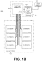
- FIGS. 1A and 1B are block diagrams of exemplary airbed environments useable with embodiments of the described principles
- FIG. 2 is flowchart illustrating offset calibration according to an embodiment of the described principles
- FIGS. 3A and 3B are flowcharts illustrating calibration processes according to embodiments of the described principles
- FIG. 4 is a flowchart illustrating an on-the-fly calibration process (or “learning algorithm”) according to an embodiment of the described principles
- FIGS. 5A and 5B are exemplary graphs illustrating pressure measurements taken during exemplary calibration processes.
- FIG. 6 is a flowchart illustrating an exemplary inflate or deflate operation utilizing embodiments of the described principles.
- FIGS. 1A and 1B Exemplary airbed environments with which embodiments of the invention may be used are depicted by FIGS. 1A and 1B . It will be appreciated that the described environments are examples, and do not imply any limitation regarding the use of other environments to practice the invention.
- the airbed environment 100 a includes a control housing 110 and an air mattress 120 .
- the control housing further includes a control unit 114 and a pump 111 , wherein the pump 111 is connected to chambers A 121 and B 122 via an appropriate connection (e.g., tubing).
- the pump 111 is connected to the chambers through tubes 113 , 115 and 116 and a manifold 112 , and the pathways include valves (not depicted) suitable for isolating/connecting the chambers to/from the manifold, isolating/connecting the manifold to atmosphere, etc.
- tube 113 is representative of two output tubes.
- chambers A 121 and B 122 may be two chambers of a single air bladder divided into the two chambers by a shared wall within the single air bladder.
- the valves may be provided at the connection between the manifold 112 and the tubes 113 , 115 , and 116 , and the valves may be in communication with the control unit 114 such that the control unit is configured to open and close the valves.
- Solenoid plunger style valves may be preferable due to their electromechanical control capabilities and relatively low cost, but it will be appreciated that other types of valves may be used.
- the tubes may be Polyvinyl Chloride (PVC) or silicone rubber or may be any other appropriate connections for transferring a gas, such as air, from a pump outlet to air mattress chambers.
- the manifold 112 may be manufactured out of thermoplastic or any other suitable type of material with sufficient mechanical strength to contain the amount of pressure required.
- materials such as Nylon PA6, Acrylonitrile Butadiene Styrene (ABS), Polypropylene (PP), Polycarbonate (PC), or Polyphenylene Ether (PPE), may be used.
- ABS Acrylonitrile Butadiene Styrene
- PP Polypropylene
- PC Polycarbonate
- PPE Polyphenylene Ether
- One skilled in the art will appreciate that the type of material used may vary depending on the pressure requirements of the particular application (e.g. a properly designed PPE manifold may withstand up to several hundred psi).
- a pressure sensor 140 (or multiple pressure sensors) are incorporated in the control unit, and may be exposed to the manifold (or air mattress chambers directly) via pressure taps to monitor the pressure status of the chambers.
- the pressure sensor 140 provides the control unit 114 with pressure information corresponding to the manifold or a respective air mattress chamber.
- the pressure sensor 140 is depicted as having a pressure tap 141 within the manifold 112 .
- Other alternative environments may include multiple pressure taps (corresponding to one or more pressure sensors at the control unit) disposed, for example, in tubing connecting the manifold to respective chambers of the air mattress.
- the control unit 114 preferably further includes a printed circuit board assembly (PCBA) with a tangible, computer-readable medium having electronically-executable instructions stored thereon (e.g. RAM, ROM, PROM, volatile, nonvolatile, or other electronic memory mechanism), and a corresponding processor for executing those instructions.
- PCBA printed circuit board assembly
- the control unit 114 controls the pump 111 and the flow of gas in the airbed environment through the tubes 113 , 115 , and 116 by opening and closing the appropriate valves.
- the control unit 114 may further send and receive data to and from a user remote 130 , allowing a user of the airbed environment 100 to control the pumping of the air mattress 120 through the control unit 114 , as well as displaying information related to the airbed environment 100 a to the user.
- An exemplary remote 130 includes a display that indicates a current pressure status of the chambers of the air mattress 120 or a current pressure target for the chambers, and also includes input buttons that allow the user to communicate the user's desired pressure settings to the control unit 114 .
- the user remote 130 may be connected to the control unit 114 through a wired connection as depicted, or may communicate with the control unit 114 wirelessly through appropriate communications hardware (e.g., certain implementations may include the user remote 130 being a mobile computing device running an application that wirelessly provides instructions to the control unit 114 ).
- the airbed environment 100 a is merely exemplary and that the principles described herein are not limited to the environment 100 depicted.
- a mattress 120 with only one chamber may be used.
- a mattress 120 with more than two chambers may be provided, with the appropriate number of connections to those mattresses.
- the manifold 112 may be connected directly to the pump outlet without the use of a tube 113 , and in yet another alternative embodiment, the manifold 112 may be located inside the mattress 120 instead of within the control housing 110 .
- FIG. 1B depicts another exemplary airbed environment 100 b .
- the environment 100 b depicted in FIG. 1B is similar to the environment 100 a depicted in FIG. 1A , as it also includes a control unit 114 , a control housing 110 , an air mattress 120 , a user remote 130 , and a pressure sensor 140 connected to a pressure tap 141 disposed within a manifold.
- the pump and manifold are combined in an integrated housing 150
- the air mattress 120 is depicted with six chambers instead of two chambers (although it will be appreciated that both environments 100 a and 100 b may be adapted to accommodate a mattress with any number of chambers). Connections between the integrated housing 150 and the six chambers are shown, with one connecting tube for each chamber.
- the integrated housing 150 may have a different number, such as four outlets, to accommodate six chambers.
- the tubes connected to two of the outlets may be divided by a splitter such that one outlet may service two chambers (e.g. chambers 1 and 3 and chambers 4 and 6 being serviced by the same outlet via a splitter).
- the integrated housing 150 of environment 100 b and the manifold 112 of environment 100 a may be configured with any number of outlets connected to any number of chambers within an air mattress by appropriate connections and splitters.
- an integrated housing 150 or manifold 112 with, for example, six outlets may be used together with an air mattress with, for example, two chambers, as unused outlets can simply be closed.
- a single control housing 110 is readily adaptable for use with a variety of air mattresses.
- control unit 114 may direct inflate and deflate operations with respect to the air mattress 120 .
- One exemplary way of controlling inflation and deflation of the air mattress is for a user to provide a continuous inflate or deflate command via the user remote 130 (e.g., by pressing and holding a corresponding button), such that the airbed system continuously inflates or deflates one or more selected chambers of an air mattress so long as the command is being given.
- the user indicates that inflation or deflation is to stop (e.g., by releasing a corresponding button)
- the inflation or deflation of the one or more selected chambers stops.
- Targeted Inflate/Deflate or Memory Recall Another exemplary way of controlling inflation and deflation of an air mattress is for a user to provide a specific target pressure (e.g., as indicated by an arbitrary relative number such as a “Sleep Number,” or as indicated by a particular pressure level such as an amount of psi), either by inputting the desired target pressure via the user remote 130 (targeted inflate/deflate), or by instructing the air bed system via the user remote 130 to inflate or deflate, as appropriate, to achieve a previously stored pressure level (memory recall).
- a specific target pressure e.g., as indicated by an arbitrary relative number such as a “Sleep Number,” or as indicated by a particular pressure level such as an amount of psi
- the user can store one or more preferred settings corresponding to one or more chambers of the air mattress into the memory of the control unit, such that the user can use the user remote 130 to later recall such settings at the press of a button.
- Auto-Inflate/Deflate Another exemplary way of controlling inflation and deflation of an air mattress is for a user simply to provide an input to inflate the air chamber to a maximum amount or to deflate the air chamber to a minimum amount.
- the user may press a corresponding auto-inflate or auto-deflate button on the user remote 130 , and the airbed system will inflate/deflate one or more selected chambers of an air mattress until entirely full/empty in response.
- control unit may rely on a determination that a dynamically-obtained static pressure measurement (as will be discussed in further detail below) for an air mattress chamber being auto-inflated or auto-deflated has reached a threshold amount to determine when the air mattress is full (for auto-inflate) or empty (for auto-deflate). Further, as will be discussed in further detail below, for auto-inflate operations, the control unit may deliberately over-inflate the air mattress chamber (or have a relatively higher threshold amount set) to account for the effects of thermodynamic cooling.
- control operations may include sophisticated inflate/deflate routines utilized in medical applications where the control unit performs various inflate and deflate procedures with respect to different chambers of an air mattress at set times to move a patient on the air mattress as specified by the corresponding routine.
- the user remote 130 may be configured in various ways and utilize different communications protocols to communicate with the control unit 114 .
- the user remote 130 simply contains two buttons (one for inflate and one for deflate) and is connected to two switches of the control unit 114 via a wired connection that utilizes two supply lines connected to I/O pins on a processor of the control unit 114 . Pressing a button on the remote causes a corresponding command to be carried out by the control unit 114 (e.g., closing a switch to drop one of the line voltages to zero is registered by the control unit as a command to pump or dump depending on which button is pressed).
- the user remote 130 includes more than two buttons and utilizes a wired, serial communications protocol to communicate with the control unit 114 .
- the user remote 130 includes a Universal Asynchronous Receiver/Transmitter (UART), connected to the control unit 114 via transmit and receive lines, and communicates various codes to and from the control unit 114 to indicate the status of buttons of the user remote 130 and to receive information/indications to be presented to the user via the remote (e.g., via LEDs or a LCD display of the remote).
- UART Universal Asynchronous Receiver/Transmitter
- the user remote 130 utilizes a wireless serial communications protocol to communicate with the control unit 114 , such as Bluetooth, WiFi, infrared, or conventional radiofrequency.
- the control unit 114 includes a wireless module having a transceiver capable of communicating with the user remote 130 via the corresponding wireless communications protocol.
- the user remote 130 is a computing device suited for various uses apart from the airbed system, such as a mobile phone, tablet computer, laptop computer, or desktop computer.
- the computing device has an appropriate application installed thereon for providing a user interface for controlling operation of the airbed system, and has appropriate hardware for communicating with the airbed system (e.g., a wireless transceiver capable of communicating over a wireless communications protocol—such as Bluetooth, WiFi, infrared, conventional radiofrequency, or a cellular communications protocol—compatible with a wireless transceiver of the control unit).
- a wireless transceiver capable of communicating over a wireless communications protocol—such as Bluetooth, WiFi, infrared, conventional radiofrequency, or a cellular communications protocol—compatible with a wireless transceiver of the control unit.
- control unit 114 is further able to communicate with the user remote 130 or other computing devices to obtain remote firmware or software updates, as well as provide alternative avenues by which the airbed system can be controlled or provide performance/user data. (e.g., allowing control both through the user remote 130 and through a mobile application on a smartphone).
- Embodiments of the invention are usable in connection with the exemplary airbed environments discussed above (as well as other airbed environments) to obtain accurate pressure readings on-the-fly (i.e., while the pump is in operation and/or while air is flowing proximate to the pressure tap for a respective pressure sensor).
- embodiments of the invention determine a relationship between static pressure measurements taken while air is static proximate to the pressure tap for a pressure sensor and comparable dynamic pressure measurements taken while air is flowing proximate to the pressure tap, wherein the determined relationship includes calibration for the specific airbed system configuration so as to account for a large number of potential variables in the way in which the airbed system is configured. This relationship is then applied to subsequent inflate and deflate operations, and further may be updated according to pressure readings taken during such subsequent inflate and deflate operations.
- SCP Static Chamber Pressure
- DMP Dynamic Manifold Pressure
- M and B constants.
- a corresponding SCP can be dynamically determined based on the relationship above without actually requiring any static measurement.
- the corresponding SCP value can be determined as if, as soon as the DMP value is read, the pump were to be shut off with the system waiting for the pressure in the chamber and the manifold to equalize/stabilize such that the pressure sensor could then take a static chamber pressure reading.
- each pneumatically-independent chamber of the system will have its own M inflate and B inflate constants and M deflate and B deflate constants.
- the control unit of the system can be configured to determine and store the following variables: M inflate1 , B inflate1 , M deflate1 and B deflate1 for a first chamber, and M inflate2 , B inflate2 , M deflate2 and B deflate2 for a second chamber.
- practical variables in the environment and the system that need to be accounted for in calibrating the relationship between SCP and DMP for each chamber includes the impact of differences in mattress, pump, tubing and valve construction and configuration (for example, variances attributable to pump output variation, molding flash or glue in any flow path, variability of solenoid retraction, asymmetric location of the pressure transducer port in the manifold, length of tubing connection between manifold and chamber, use of air hold quick disconnects versus simple double barb fittings, internal flow resistance of chamber zones, and/or irregularities in flow geometry such as a kink in the tubing).
- differences in mattress, pump, tubing and valve construction and configuration for example, variances attributable to pump output variation, molding flash or glue in any flow path, variability of solenoid retraction, asymmetric location of the pressure transducer port in the manifold, length of tubing connection between manifold and chamber, use of air hold quick disconnects versus simple double barb fittings, internal flow resistance of chamber zones, and/or irregularities in flow geometry
- this system-based calibration (using M and B constants) allow for changes in the system configuration over time (e.g., due to wear and tear of the air mattress construction or certain elements of the pump, or other changes in shape and/or configuration of components of the air mattress and/or pumping system) to be accounted for as well.
- embodiments of the invention have been demonstrated as being able to accurately measure and display static pressure corresponding to an air chamber during pump operation, and to automatically calibrate the measurement system to allow for accuracy of +/ ⁇ 0.01 psi.
- embodiments of the invention provide for highly accurate measurement (and display, if desired) of what the “static” pressure of an air mattress chamber is while air is still flowing proximate to the pressure sensor—i.e., even though a true “static” pressure reading is not possible while air is flowing, the static chamber pressure can still be dynamically obtained. This allows for inflation and deflation operations to be performed in an airbed system with the benefit of an accurately monitored pressure within an air mattress chamber being operated upon without the noise and delay associated with conventional stop-and-check measurement systems.
- embodiments of the invention are both faster and quieter, as well as more accurate, than conventional systems, and may be particularly suitable for medical applications requiring very accurate pressure control (e.g., tolerances of ⁇ 0.01 psi). Additionally, the embodiments of the invention are able to achieve the advantages of being fast, quiet, and accurate while using relatively inexpensive hardware for pressure sensing (e.g., low-cost pressure transducers).
- two calibration processes are performed to determine the M and B values discussed above.
- An “Offset Calibration” is performed to calibrate the airbed system and pressure sensors with respect to current environmental conditions (e.g., with respect to temperature and atmospheric pressure).
- a “System Calibration” is also performed to calibrate the system and pressure sensors with respect to the specific configuration of the physical components of the entire system. It will be appreciated that these two calibration processes may be performed separately or together, and may have different triggering conditions (e.g., in response to the airbed system being turned on, in response to a user command to calibrate, in response to detection of certain conditions, etc.).
- the System Calibration is performed in response to only the first time the pumping system is turned on and/or in response to a specific request for System Calibration from a user, while the Offset Calibration is performed prior to each System Calibration procedure, each time the pumping system is powered on, each time the user remote wakes up (e.g., goes from a dark state to a lit-up state), each time an on-demand calibration procedure is requested, each time a control operation (e.g., deflate/inflate) is initiated for any air chamber, and/or in response to a specific request for Offset Calibration from a user.
- the System Calibration utilizes gage pressure based on the offset measurement determined according to the Offset Calibration.
- Low-cost pressure transducers are generally not calibrated to compensate for excursions of temperature or changes in atmospheric pressure, but both of these factors can significantly impact the values read by a pressure transducer. Accordingly, for embodiments of the invention using low-cost pressure transducers that are not calibrated for temperature and atmospheric pressure, the airbed system utilizes gage pressure readings instead of absolute pressure readings, by determining, via the Offset Calibration, an initial atmospheric reading and deducting that initial atmospheric reading (i.e., the “offset”) from all subsequent pressure readings.
- the airbed system can adapt itself to various environments and, for example, to account for differences between the location of manufacture and the location of use (e.g., in the case of an airbed system being initially manufactured at a low altitude and then shipped to a region of high altitude for use).
- FIG. 2 is a flowchart 200 illustrating an exemplary process for performing the Offset Calibration.
- the manifold is isolated from the air mattress chambers (e.g., by closing all the chamber solenoids) and exposed to the atmospheric environment surrounding the airbed system (e.g., by opening a drain/exhaust solenoid). This exposes the pressure transducer within the manifold to the current atmospheric pressure and temperature.
- An offset measurement is then taken at stage 203 , which can be used by the airbed system to determine gage/delta pressure readings instead of absolute pressure readings (i.e., by deducting the offset measurement from subsequent pressure readings obtained by the pressure sensor).
- obtaining the offset measurement may include passing a pressure transducer voltage through a hardware filter (e.g., corresponding to a time period of ⁇ 23 ms), using an analog-to-digital converter to obtain a digital signal corresponding to the hardware-filtered voltage, and then applying a two-pole software filter to the digital signal to obtain the offset measurement.
- a hardware filter e.g., corresponding to a time period of ⁇ 23 ms
- Embodiments of the invention provide different ways of calibrating pressure measurements of an airbed system for inflate and deflate operations.
- FIGS. 3A and 3B are flowcharts illustrating a dedicated system calibration procedure to determine M and B values for inflation and deflation, respectively.
- the calibration procedures depicted in FIGS. 3A and 3B may be, for example, initiated in response to a user command to perform calibration and/or automatically in response to the airbed system powering on.
- the system calibration procedures are only performed in response to a specific user command for calibration (e.g., to prevent unwanted calibrations from being performed in situations such as power outages).
- the command for calibration may be directed to calibrating all of the chambers for both inflate and deflate operations—or, alternatively, may be directed to calibrating a specific chamber and/or for a specific operation (e.g., just inflate or just deflate).
- the flowchart 300 a of FIG. 3A illustrates a process for calibration of a specific chamber that determines M and B values for that chamber corresponding to inflation by the airbed pumping system.
- the control unit of the system performs a static measurement (i.e., a measurement where the pressure tap is in fluid communication with the air chamber(s) to be measured while being isolated from other chambers and from the external environment, and while air is not flowing proximate to the pressure tap) to determine whether the pressure in the chamber is too high to perform inflation calibration (if the chamber is already at or near a maximum pressure, the calibration procedure will be less accurate).
- a static measurement i.e., a measurement where the pressure tap is in fluid communication with the air chamber(s) to be measured while being isolated from other chambers and from the external environment, and while air is not flowing proximate to the pressure tap
- the system deflates the chamber for a period of time at stage 303 to bring the chamber down to an appropriate pressure for starting the inflate calibration procedure.
- stage 301 (and stage 303 ) need not be performed, for example, if the static pressure of the air mattress is already known to be low enough to perform the inflate calibration procedure (for example, when an inflate calibration procedure for the chamber is performed immediately after a deflate calibration procedure for that chamber).
- the pump is then turned on to inflate the air mattress chamber for a relatively short period of time (e.g., 1 second).
- a pressure measurement is saved as a DMP LOW value.
- the pump is turned off, a short time (e.g., 1 second) is allowed to elapse for the pressure within the manifold to equalize with the pressure in the chamber, and then a pressure measurement taken after the elapsed time is saved as a SCP LOW value corresponding to the DMP LOW value.
- the pump is then turned on to inflate the air mattress for a relatively long period of time at stage 311 .
- the period of time that would be sufficient varies depending on the size of the chamber, but does not need to be precise (one way to determine when to stop the inflate is to set a pressure target near the top of an expected pressure range; alternatively, a time period of, for example, 2 minutes could be set).
- Measurements are taken to obtain DMP HIGH and SCP HIGH values (i.e., by saving a pressure measurement taken right before the pump is turned off again as DMP HIGH at stage 313 , and then turning off the pump waiting for an elapsed time, and saving a pressure measurement taken after the elapsed time as SCP HIGH at stage 315 ).
- M inflate and B inflate for that chamber are determined based on the data pairs DMP LOW with SCP LOW and DMP HIGH with SCP HIGH .
- the flowchart 300 b of FIG. 3B illustrates a process for calibration of a specific chamber that determines M and B values for that chamber corresponding to deflation by the airbed pumping system.
- the control unit of the system checks performs a static measurement to determine whether the pressure in the chamber is too low to perform deflation calibration (e.g., if the chamber is already at or near a minimum pressure, the calibration procedure will be less accurate). In response to determining that the chamber is above a threshold pressure at stage 321 , the system inflates the chamber for a period of time at stage 323 to bring the chamber up to an appropriate pressure for starting the inflate calibration procedure.
- stage 321 (and stage 323 ) need not be performed, for example, if the static pressure of the air mattress is already known to be high enough to perform the deflate calibration procedure (for example, when a deflate calibration procedure for the chamber is performed immediately after an inflate calibration procedure for that chamber).
- the air mattress chamber is then deflated (e.g., by exposing the chamber to an exhaust via the manifold and/or by dumping the air from the chamber using the pump) for a relatively short period of time (e.g., 1 sec).
- a relatively short period of time e.g. 1 sec.
- a pressure measurement taken while the air is flowing is saved as a DMP HIGH value.
- a short time e.g., 1 sec
- a static pressure measurement taken after the elapsed time is saved as a SCP HIGH value corresponding to the DMP HIGH value.
- the deflation is then continued for a relatively long period of time at stage 331 , and measurements are taken to obtain DMP LOW and SCP LOW values (i.e., by saving a pressure measurement taken right before the deflation is stopped off again as DMP LOW at stage 333 , and then stopping the deflation, waiting for an elapsed time, and saving a pressure measurement taken after the elapsed time as SCP LOW at stage 335 ).
- M deflate and B deflate for that chamber are determined based on the data pairs DMP LOW with SCP LOW and DMP HIGH with SCP HIGH .
- FIGS. 3A and 3B can be executed and repeated for all chambers of an air mattress in any order to determine a complete calibration for all of the chambers, and/or can be individually performed for particular chambers one at a time on an on-demand basis.
- SCP and DMP values discussed above, as utilized by the system may be values that are representative of pressure (and that can be converted to units of pressure by the control unit if desired), but need not be expressed directly in terms of a pressure unit such as psi. Further, for example, in an exemplary implementation using a non-floating point processor in the control unit, SCP and DMP values may be multiplied by 256 to put the calculations performed by the processor in the range of integer math. Thus, it will be appreciated that the particular units of measurement and numerical range for the SCP and DMP values are not important so long as those values are representative of pressure.
- FIGS. 3A and 3B can be performed together (e.g., one after another) as part of a single calibration procedure and may, for example, be requested on demand or be based upon some other trigger (e.g., detecting that the pumping system is powered on for the first time with respect to a new air mattress chamber configuration).
- the calibration procedure(s) are part of a comprehensive self-test of the airbed system, for example, including but not limited to checking solenoid actuation, manifold pressure integrity, pressure tube connection integrity, motor operation, firmware, main PCBA, integrity of the motor/pump-to-manifold tube connections, drain solenoid and drain port, wireless connection with the user remote, etc.
- errors that are found may be indicated on the user remote (or via the display of another user interface in communication with the pumping system).
- FIGS. 3A and 3B illustrate exemplary embodiments of “dedicated” calibration procedures aimed at determining M and B values for a particular system configuration
- other exemplary embodiments of the invention include on-the-fly, “dynamic” calibration that is able to “learn” and/or update the M and B values for a particular system configuration simultaneously with actual inflate and deflate operations requested by a user during practical use of the airbed system by the user.
- FIG. 4 includes a flowchart illustrating an exemplary process 400 where, for each chamber, a number of data pairs for SCP and DMP are updated based on new data pairs determined from actual use of the airbed system to update M and B values on the fly.
- the airbed system may be preprogrammed with default M and B values (e.g., for particular chambers) and/or DMP-SCP data pairs. Or, if not preprogrammed with default values and/or data pairs, initial M and B values can be determined via a dedicated calibration procedure as discussed above with respect to FIGS. 3A and 3B ). These default and/or initial M and B values can then be updated on-the-fly according to the process 400 depicted in FIG. 4 . It will be appreciated that, if default M and B values are used, they may start off as being slightly or somewhat inaccurate for a particular air mattress configuration. However, once the M and B values are updated, e.g. via a dedicated calibration procedure (e.g., FIGS. 3A and 3B ) or on-the-fly according to the process 400 , dynamically-obtained static chamber pressure measurements may be accurate, for example, within +/ ⁇ 0.01 psi.
- the process 400 begins at stage 401 with the airbed system performing an inflation or deflation operation.
- This inflation or deflation operation may be, for example, based on a user actually using the airbed system to inflate or deflate an air mattress chamber as desired.
- a pressure reading from a pressure sensor in the manifold is determined to be a DMP value.
- an SCP value corresponding to that DMP value is obtained by stopping the inflate or deflate operation, waiting for a period of time for the pressure within the manifold and chamber to stabilize, and again taking a pressure reading from the pressure sensor.
- the obtained SCP and DMP values are stored by the control unit as corresponding to a pneumatically-independent chamber (or a pneumatically-independent set of chambers, such as when two chambers—e.g., Head/Foot—are pneumatically joined so as to be controlled together) and as corresponding to inflation or deflation, as appropriate based on the operation that was performed.
- the SCP and DMP values may be stored in addition to other values, while in other exemplary embodiments, the SCP and DMP values are used to overwrite previously stored values. Different examples will be discussed in further detail below.
- the M and B values corresponding to the chamber (or set of chambers) and inflation or deflation are then updated by the control unit based on the additional SCP and DMP data pair.
- the updated M and B values can then be applied to future operations of the airbed system for accurately determining pressure in the corresponding chamber during a corresponding inflation/deflation operation while air is not static at the pressure sensor.
- These updated M and B values may also be further updated based on such future operations according to subsequent iterations of the process 400 .
- the control unit only stores two data pairs for calculating each M and B value for a chamber and for inflation.
- the Chamber 1 stores DMP HIGHinflate1 , SCP HIGHinflate1 , DMP LOWinflate1 and SCP LOWinflate1 upon which M inflate1 and B inflate1 are based, and DMP HIGHdeflate1 , SCP HIGHdeflate1 , DMP LOWdeflate1 and SCP LOWdeflate1 upon which M deflate1 and B deflate1 are based.
- an appropriate DMP-SCP data pair can be updated.
- the data pair that is to be updated can be determined based on the operation that was performed (inflate or deflate) and the value of one of the measurements (e.g., the SCP measurement). For example, the control unit may consider SCP values less than 0.44 psi to be suitable for a SCP LOW data point, and utilize DMP-SCP data pairs with an SCP value of less than 0.44 psi as low-side data pairs while DMP-SCP data pairs with an SCP value of greater than or equal to 0.44 psi are used as high-side data pairs.
- the foregoing example is a relatively simple example, but may not be ideal since it may result in a DMP-SCP high-side data pair that is very close to a DMP-SCP low-side data pair (e.g., when the SCP LOW value is 0.42 psi and the SCP HIGH value is 0.44 psi).
- this situation is avoided by the use of four data pairs per chamber (e.g., a Chamber 1 ) per operation (i.e., inflate or deflate).
- each DMP-SCP data pair is defined for each chamber (or set of chambers) for each operation: LOW (e.g., from 0.10 to 0.26 psi), MID-LOW (e.g., from 0.27 to 0.43 psi), MID-HIGH (e.g., from 0.44 to 0.59 psi), and HIGH (e.g., from 0.60 to 0.75 psi).
- LOW e.g., from 0.10 to 0.26 psi
- MID-LOW e.g., from 0.27 to 0.43 psi
- MID-HIGH e.g., from 0.44 to 0.59 psi
- HIGH e.g., from 0.60 to 0.75 psi
- M and B are updated based on the newly obtained data pair in combination with a second data pair, where the second data pair is selected to be at least one step removed from the newly obtained data pair.
- the second data pair is selected to be at least one step removed from the newly obtained data pair.
- the other data pair used for calculating M and B is either a MID-HIGH data pair or a HIGH data pair (but not a MID-LOW data pair); and if the new data pair is in the MID-LOW range, the other data pair used for calculating M and B is a HIGH data pair (but not a LOW data pair or MID-HIGH data pair).
- the actual DMP and SCP values utilized in the system may not actually be in psi units, but rather in an arbitrary form and in an arbitrary range that are representative of what actual DMP and SCP measurements in pressure units would be.
- the particular values that constitute the LOW and HIGH ranges, or LOW, MID-LOW, MID-HIGH and HIGH ranges, or other ranges may vary from implementation to implementation, for example, depending on various parameters of the system.
- control unit may include a large number of fine-grained ranges for DMP-SCP data pairs and rely on more than just two data pairs for calculating M and B (for example, a linear regression function to determine best-fit values for M and B).
- control unit may store a large number of data pairs for each chamber/operation, including all previously collected data pairs.
- control unit may delete old data pairs on the basis of time expiration or on the basis of a total max limit of data pairs being exceeded (e.g., by deleting the oldest data pair and adding in a newly obtained data pair).
- the SCP and DMP measurements referred to above in the context of FIGS. 3A, 3B and 4 may be based on a “filtered” voltage corresponding to voltages read by the pressure sensor over a period of time (e.g., the average over ⁇ 0.5 seconds), and not the instantaneous voltage read by the pressure sensor, as will be discussed in further detail below.
- Pressure readings taken by a pressure sensor in an airbed system may be subject to certain types of noise or disturbances.
- two types of pressure waves may be detected by the pressure sensor. The first are the higher-frequency, steady-amplitude waves coming out of a diaphragm pump during pumping actions. The second is a longer period where decreasing amplitude waves occur after a sudden change in pressure when a valve (e.g., a solenoid) is actuated or the pump turns on or off.
- a valve e.g., a solenoid
- FIG. 5A provides an exemplary plot of pressure readings taken over time throughout an inflation procedure, showing raw voltage read by the pressure sensor over time.
- the manifold Before the point 501 , the manifold is exposed to the external environment through an exhaust valve for determining an offset voltage value via offset calibration as discussed above.
- a chamber valve e.g., a solenoid
- the pump is turned on to inflate the air mattress chamber. While the pump is on, higher-frequency, steady-amplitude waves are generated by the diaphragm pump due to the pumping action of the pump.
- the pump is turned off, again resulting in another pressure wave of decreasing-amplitude.
- Embodiments of the invention account for the existence of these pressure waves by utilizing a filtered voltage measurement instead of the instantaneous raw voltage read by the pressure sensor. This is accomplished, for example, by passing the raw voltage detected by a pressure transducer through a single-pole, low-pass hardware filter, performing an analog-to-digital conversion using an A/D converter, and passing the digital signal through a two-pole software filter to obtain an average value for voltage over a previous period of time (e.g., ⁇ 0.5 seconds).
- FIG. 5B is a plot of filtered voltage versus time corresponding to the raw voltage measurements shown in FIG. 5A . As can be seen in FIG.
- applying the voltage filter provides a steady measurement that is able to achieve an accurate reading ⁇ 0.5 seconds after a noise/disturbance-producing event occurs. For example, after the pump is turned on at stage 502 , the filtered voltage reading takes about 0.5 seconds to catch up at stage 510 , and after it catches up at stage 510 , the filtered voltage reading can be used as an accurate representation of dynamically-measured pressure for the manifold.
- either the instantaneous raw voltage or the filtered voltage can be used to determine static chamber pressure at stage 520 , since there is no ongoing disturbance in the pressure. It will be appreciated, however, that it is still preferable to use the filtered voltage at stage 520 , to provide a similar basis of comparison with respect to measurements taken while the pump is on, as well as to avoid potential noise in the pressure reading from other sources.
- the offset measurement obtained from the offset calibration process can be deducted from the filtered voltage measurement to obtain the “pressure” that is used as SCP or DMP values for the M and B calculations discussed above. Further conversion of the SCP and DMP values into units of pressure may be performed if desired (e.g., for display purposes or for control-related purposes).
- the consideration of this latency period for arriving at accurate dynamic measurements during pump operation may also be used to impose a condition upon when the control unit will attempt to update an DMP-SCP data pair in embodiments of the invention relating to FIG. 4 .
- the control unit may only perform stages 407 and 409 of FIG. 4 after verifying that the inflation or deflation operation exceeds the latency period. This ensures that a new DMP-SCP data pair will not be subject to noise-related fluctuations.
- FIG. 6 illustrates an exemplary process 600 where inflation or deflation is performed by an airbed system.
- the control unit of the airbed system determines that an inflation or deflation operation is to be performed, for example, in response to a user input on a user remote or in response to some other trigger (such as a time-based, programmed routine).
- an offset calibration may be performed, for example with respect to embodiments involving low-cost pressure transducers, to ensure that all readings taken in connection with the inflation/deflation operation can be accurately adjusting into gage pressure measurements.
- a dynamically-obtained static chamber pressure can be presented on a display of a user remote used to control the airbed system (or on some other display, such as on a computer) at stage 607 .
- dSCP values are displayed in a scrolling manner, such that, for example, when a user holds down an inflate or deflate button, the dSCP values scroll upwards or downwards in accordance with the inflation or deflation of the air mattress.
- Embodiments of the invention are able to achieve displayed dSCP values that are accurate relative to the actual corresponding SCP values in the chamber (as would be measured at the respective times) within +/ ⁇ 0.01 psi.
- the airbed system stops inflation or deflation, for example, based on user input (e.g., the user letting go of the inflate or deflate button), based on a target pressure being reached (as determined according to the dSCP values calculated by the control unit), or other conditions.
- user input e.g., the user letting go of the inflate or deflate button
- a target pressure as determined according to the dSCP values calculated by the control unit
- the control unit can then determine the actual SCP value corresponding to the chamber under static conditions at stage 611 .
- the actual measured SCP value can then be displayed to the user (e.g., on the user remote or some other computing device).
- the SCP value in combination with a corresponding DMP value obtained right before stopping the inflate or deflate operation, can also be used to update M and B values at stage 613 (as discussed above with respect to FIG. 4 ).
- some of the air mattress chambers may have shared walls such that inflation/deflation of one chamber will affect the pressure in one or more adjacent chambers.
- multiple inflate and/or deflate operations may be required to get all chambers to their respective desired pressures within an accuracy of +/ ⁇ 0.1 psi.
- getting the correct pressures into all three chambers may require multiple operations to be performed (e.g., adjustment of the Head/Foot chambers ⁇ adjustment of the Lumbar chamber ⁇ readjustment of the Head/Foot chambers ⁇ readjustment of the Lumbar chamber). Since embodiments of the invention are able to quickly and accurately determine dynamically-obtained static chamber pressure based on the dynamic manifold pressure readings taken by a pressure sensor, such multiple pass-through operation situations can be quickly and efficiently completed.
- thermodynamic cooling are accounted for by the control unit by providing deliberate overfilling based on the length of an inflate operation. This is because, particularly for relatively long inflate operations, the pressure within the chamber will drop slightly after the inflation operation is completed due to thermodynamic cooling.
- the airbed system may actually fill the air mattress to, for example, 0.78 psi, since thermodynamic cooling will subsequently cause the pressure in the air mattress to drop back down to 0.75 psi (e.g., within around 20 seconds).
- the amount of overfill is proportional relative to the length of the fill (and may be based on an parameter stored at the control unit, which in certain implementations, may be updatable based on actual pressure readings taken by the pressure sensor).
- the pressure displayed to the user on a user remote may inherently take into account the thermodynamic cooling such that it displays only what the pressure is expected to be after thermodynamic cooling has occurred (e.g., the remote will display 0.75 psi even as the chamber is actually filled to 0.78 psi, since the chamber will shortly come back down to 0.75 psi).
- the pressure transducers themselves may need certain hardware calibration procedures performed thereon. While pre-calibrated pressure transducers exist, such pre-calibrated pressure transducers cost significantly more than uncalibrated pressure transducers. Thus, to be able to use lower-cost, uncalibrated pressure transducers, the pressure transducers themselves may be calibrated to establish a gain factor which is used to compensate for variations that exist from pressure transducer to pressure transducer. This is performed by exposing the transducer to a known pressure source and calculating the gain required to generate the “correct” output corresponding to the known pressure source.
Landscapes
- Health & Medical Sciences (AREA)
- Nursing (AREA)
- Life Sciences & Earth Sciences (AREA)
- Animal Behavior & Ethology (AREA)
- General Health & Medical Sciences (AREA)
- Public Health (AREA)
- Veterinary Medicine (AREA)
- Mattresses And Other Support Structures For Chairs And Beds (AREA)
- Invalid Beds And Related Equipment (AREA)
Abstract
Description
SCP=M*DMP+B
where SCP is Static Chamber Pressure, DMP is Dynamic Manifold Pressure, and M and B are constants. Thus, for each DMP determined by a pressure sensor, a corresponding SCP can be dynamically determined based on the relationship above without actually requiring any static measurement. In other words, for a DMP value read by a pressure sensor, the corresponding SCP value can be determined as if, as soon as the DMP value is read, the pump were to be shut off with the system waiting for the pressure in the chamber and the manifold to equalize/stabilize such that the pressure sensor could then take a static chamber pressure reading.
M inflate=(SCPHIGH−SCPLOW)/(DMPHIGH−DMPLOW);
B inflate=SCPHIGH−(M inflate*DMPHIGH)
[or alternatively, B inflate=SCPLOW−(M inflate*DMPLOW)].
M deflate=(SCPHIGH−SCPLOW)/(DMPHIGH−DMPLOW);
B deflate=SCPHIGH−(M deflate*DMPHIGH)
[or alternatively, B deflate=SCPLOW−(M deflate*DMPLOW)].
Claims (24)
Priority Applications (2)
| Application Number | Priority Date | Filing Date | Title |
|---|---|---|---|
| US15/877,018 US10849436B2 (en) | 2013-12-16 | 2018-01-22 | Airbed pump calibration and pressure measurement |
| US17/106,136 US12161228B2 (en) | 2013-12-16 | 2020-11-29 | Methods for airbed pump calibrations and pressure measurements |
Applications Claiming Priority (3)
| Application Number | Priority Date | Filing Date | Title |
|---|---|---|---|
| US201361916516P | 2013-12-16 | 2013-12-16 | |
| US14/571,834 US9913547B2 (en) | 2013-12-16 | 2014-12-16 | Airbed pump calibration and pressure measurement |
| US15/877,018 US10849436B2 (en) | 2013-12-16 | 2018-01-22 | Airbed pump calibration and pressure measurement |
Related Parent Applications (1)
| Application Number | Title | Priority Date | Filing Date |
|---|---|---|---|
| US14/571,834 Continuation US9913547B2 (en) | 2013-12-16 | 2014-12-16 | Airbed pump calibration and pressure measurement |
Related Child Applications (1)
| Application Number | Title | Priority Date | Filing Date |
|---|---|---|---|
| US17/106,136 Continuation-In-Part US12161228B2 (en) | 2013-12-16 | 2020-11-29 | Methods for airbed pump calibrations and pressure measurements |
Publications (2)
| Publication Number | Publication Date |
|---|---|
| US20180140107A1 US20180140107A1 (en) | 2018-05-24 |
| US10849436B2 true US10849436B2 (en) | 2020-12-01 |
Family
ID=53366928
Family Applications (2)
| Application Number | Title | Priority Date | Filing Date |
|---|---|---|---|
| US14/571,834 Active 2035-03-25 US9913547B2 (en) | 2013-12-16 | 2014-12-16 | Airbed pump calibration and pressure measurement |
| US15/877,018 Active 2035-12-21 US10849436B2 (en) | 2013-12-16 | 2018-01-22 | Airbed pump calibration and pressure measurement |
Family Applications Before (1)
| Application Number | Title | Priority Date | Filing Date |
|---|---|---|---|
| US14/571,834 Active 2035-03-25 US9913547B2 (en) | 2013-12-16 | 2014-12-16 | Airbed pump calibration and pressure measurement |
Country Status (2)
| Country | Link |
|---|---|
| US (2) | US9913547B2 (en) |
| WO (1) | WO2015095125A1 (en) |
Families Citing this family (26)
| Publication number | Priority date | Publication date | Assignee | Title |
|---|---|---|---|---|
| US20140345058A1 (en) * | 2013-05-21 | 2014-11-27 | SEC Medical Development, Inc. | Pressure Monitoring and Management Cushion System And Method Of Use |
| WO2015095125A1 (en) * | 2013-12-16 | 2015-06-25 | Rapid Air Llc | Airbed pump calibration and pressure measurement |
| US12161228B2 (en) * | 2013-12-16 | 2024-12-10 | American National Manufacturing, Inc. | Methods for airbed pump calibrations and pressure measurements |
| US10674832B2 (en) * | 2013-12-30 | 2020-06-09 | Sleep Number Corporation | Inflatable air mattress with integrated control |
| US10448749B2 (en) * | 2014-10-10 | 2019-10-22 | Sleep Number Corporation | Bed having logic controller |
| US10085569B2 (en) * | 2015-03-20 | 2018-10-02 | Apex Medical Corp. | Inflation and deflation pressure regulation system |
| US10254727B2 (en) * | 2015-06-04 | 2019-04-09 | Hill-Rom Services, Inc. | Feedback control for a person support apparatus with a mattress replacement system and methods for automatically pausing a turn and hold operation |
| US10267706B2 (en) * | 2015-06-30 | 2019-04-23 | Stryker Corporation | Pneumatic diagnostic method and system for detecting leakage in a pneumatic system |
| US10149549B2 (en) | 2015-08-06 | 2018-12-11 | Sleep Number Corporation | Diagnostics of bed and bedroom environment |
| EP3362688B1 (en) | 2015-10-16 | 2024-07-31 | Intex Marketing Ltd. | Multifunctional air pump |
| AU2017213658B2 (en) * | 2016-02-04 | 2023-01-05 | Roho, Inc. | System and method for cushion inflation |
| CN206368786U (en) | 2016-12-08 | 2017-08-01 | 明达实业(厦门)有限公司 | The attachment structure of pump and aerated product |
| CN208669644U (en) | 2018-05-16 | 2019-03-29 | 明达实业(厦门)有限公司 | A pump with multi-channel inflation and deflation function |
| EP4379217A3 (en) | 2017-11-27 | 2024-08-28 | Intex Marketing Ltd. | Manual inflation and deflation adjustment structure of a pump |
| US20210227990A1 (en) * | 2018-05-10 | 2021-07-29 | The Coleman Company, Inc. | Air pump with automatic pressure maintenance |
| US11439249B2 (en) * | 2019-01-22 | 2022-09-13 | Shang-Neng Wu | Pressure reference resetting structure of inflatable mattress |
| CN113677245A (en) * | 2019-02-22 | 2021-11-19 | 布莱特有限公司 | Pneumatic management system of sleep platform |
| WO2020174418A1 (en) | 2019-02-26 | 2020-09-03 | Hill-Rom Services, Inc. | Patient positioning apparatus and mattress |
| US11698075B2 (en) | 2019-06-21 | 2023-07-11 | Intex Marketing Ltd. | Inflatable product having electric and manual pumps |
| US11712386B2 (en) | 2019-07-15 | 2023-08-01 | Hill-Rom Services, Inc. | Pneumatic system blockage detection |
| TWI787818B (en) * | 2021-05-14 | 2022-12-21 | 世大化成股份有限公司 | Management system of pressure sensing mattress |
| WO2023086476A1 (en) * | 2021-11-15 | 2023-05-19 | Sleep Number Corporation | Air mattress with features for determining ambient temperature |
| CN216822505U (en) * | 2021-12-31 | 2022-06-28 | 明达实业(厦门)有限公司 | Internal pressure adjusting structure of multi-air-chamber inflatable product |
| CN115708634B (en) * | 2022-11-09 | 2024-11-12 | 慕思健康睡眠股份有限公司 | Mattress inflation control method, device, mattress and storage medium |
| CN118836183B (en) * | 2024-07-12 | 2025-07-22 | 旺利塑胶电子(惠州)有限公司 | Wire control air pump for multi-air-chamber inflatable product and control method thereof |
| CN119103110A (en) * | 2024-10-22 | 2024-12-10 | 旺利塑胶电子(惠州)有限公司 | Air pump device with automatic air replenishment function and use method thereof |
Citations (18)
| Publication number | Priority date | Publication date | Assignee | Title |
|---|---|---|---|---|
| US5020176A (en) | 1989-10-20 | 1991-06-04 | Angel Echevarria Co., Inc. | Control system for fluid-filled beds |
| US5848450A (en) | 1996-03-05 | 1998-12-15 | L&P Property Management Company | Air bed control |
| US6047423A (en) | 1998-07-27 | 2000-04-11 | Larson; Lynn D. | Air mattress with firmness adjusting air bladders |
| US6058537A (en) | 1998-07-13 | 2000-05-09 | Larson; Lynn D. | Pressure control apparatus for air mattresses |
| US6115860A (en) | 1986-09-09 | 2000-09-12 | Kinetic Concepts, Inc. | Feedback controlled patient support |
| US6483264B1 (en) * | 1994-11-01 | 2002-11-19 | Select Comfort Corporation | Air control system for an air bed |
| US6686711B2 (en) | 2000-11-15 | 2004-02-03 | Comfortaire Corporation | Air mattress control system and method |
| US20060053561A1 (en) | 2004-09-13 | 2006-03-16 | The Coleman Company, Inc. | Airbed with built-in air pump |
| US7225488B2 (en) | 2001-03-26 | 2007-06-05 | Sunflower Medical, L.L.C. | Air mattress control unit |
| US20070227594A1 (en) | 2006-04-04 | 2007-10-04 | Chaffee Robert B | Method and apparatus for monitoring and controlling pressure in an inflatable device |
| US20090314354A1 (en) | 2006-04-04 | 2009-12-24 | Chaffee Robert B | Method and apparatus for monitoring and controlling pressure in an inflatable device |
| US7886387B2 (en) | 2007-01-26 | 2011-02-15 | Rapid Air Llc | Multiple configuration air mattress pump system |
| US20110138539A1 (en) | 2008-04-04 | 2011-06-16 | Select Comfort Corporation | System and method for improved pressure adjustment |
| US20120304391A1 (en) * | 2011-03-21 | 2012-12-06 | Rapid Air Llc | Pump and housing configuration for inflating and deflating an air mattress |
| US20130031725A1 (en) * | 2011-08-02 | 2013-02-07 | Rapid Air, Llc | System and Method for Controlling Air Mattress Inflation and Deflation |
| US9149126B2 (en) | 2006-08-29 | 2015-10-06 | Martin B Rawls-Meehan | Methods and systems of an adjustable bed |
| US9510688B2 (en) * | 2013-03-14 | 2016-12-06 | Select Comfort Corporation | Inflatable air mattress system with detection techniques |
| US9913547B2 (en) * | 2013-12-16 | 2018-03-13 | American National Manufacturing, Inc. | Airbed pump calibration and pressure measurement |
-
2014
- 2014-12-16 WO PCT/US2014/070494 patent/WO2015095125A1/en not_active Ceased
- 2014-12-16 US US14/571,834 patent/US9913547B2/en active Active
-
2018
- 2018-01-22 US US15/877,018 patent/US10849436B2/en active Active
Patent Citations (19)
| Publication number | Priority date | Publication date | Assignee | Title |
|---|---|---|---|---|
| US6115860A (en) | 1986-09-09 | 2000-09-12 | Kinetic Concepts, Inc. | Feedback controlled patient support |
| US5020176A (en) | 1989-10-20 | 1991-06-04 | Angel Echevarria Co., Inc. | Control system for fluid-filled beds |
| US6483264B1 (en) * | 1994-11-01 | 2002-11-19 | Select Comfort Corporation | Air control system for an air bed |
| US5848450A (en) | 1996-03-05 | 1998-12-15 | L&P Property Management Company | Air bed control |
| US6058537A (en) | 1998-07-13 | 2000-05-09 | Larson; Lynn D. | Pressure control apparatus for air mattresses |
| US6047423A (en) | 1998-07-27 | 2000-04-11 | Larson; Lynn D. | Air mattress with firmness adjusting air bladders |
| US6686711B2 (en) | 2000-11-15 | 2004-02-03 | Comfortaire Corporation | Air mattress control system and method |
| US7225488B2 (en) | 2001-03-26 | 2007-06-05 | Sunflower Medical, L.L.C. | Air mattress control unit |
| US20060053561A1 (en) | 2004-09-13 | 2006-03-16 | The Coleman Company, Inc. | Airbed with built-in air pump |
| US20070227594A1 (en) | 2006-04-04 | 2007-10-04 | Chaffee Robert B | Method and apparatus for monitoring and controlling pressure in an inflatable device |
| US20090314354A1 (en) | 2006-04-04 | 2009-12-24 | Chaffee Robert B | Method and apparatus for monitoring and controlling pressure in an inflatable device |
| US9149126B2 (en) | 2006-08-29 | 2015-10-06 | Martin B Rawls-Meehan | Methods and systems of an adjustable bed |
| US7886387B2 (en) | 2007-01-26 | 2011-02-15 | Rapid Air Llc | Multiple configuration air mattress pump system |
| US20110138539A1 (en) | 2008-04-04 | 2011-06-16 | Select Comfort Corporation | System and method for improved pressure adjustment |
| US8769747B2 (en) * | 2008-04-04 | 2014-07-08 | Select Comfort Corporation | System and method for improved pressure adjustment |
| US20120304391A1 (en) * | 2011-03-21 | 2012-12-06 | Rapid Air Llc | Pump and housing configuration for inflating and deflating an air mattress |
| US20130031725A1 (en) * | 2011-08-02 | 2013-02-07 | Rapid Air, Llc | System and Method for Controlling Air Mattress Inflation and Deflation |
| US9510688B2 (en) * | 2013-03-14 | 2016-12-06 | Select Comfort Corporation | Inflatable air mattress system with detection techniques |
| US9913547B2 (en) * | 2013-12-16 | 2018-03-13 | American National Manufacturing, Inc. | Airbed pump calibration and pressure measurement |
Non-Patent Citations (1)
| Title |
|---|
| International Search Report and Written Opinion for co-pending International Application No. PCT/US2014/070494 dated Mar. 19, 2015. |
Also Published As
| Publication number | Publication date |
|---|---|
| WO2015095125A1 (en) | 2015-06-25 |
| US9913547B2 (en) | 2018-03-13 |
| US20150164236A1 (en) | 2015-06-18 |
| US20180140107A1 (en) | 2018-05-24 |
Similar Documents
| Publication | Publication Date | Title |
|---|---|---|
| US10849436B2 (en) | Airbed pump calibration and pressure measurement | |
| US12161228B2 (en) | Methods for airbed pump calibrations and pressure measurements | |
| US20210244196A1 (en) | System and Method for Improved Pressure Adjustment | |
| US8832886B2 (en) | System and method for controlling air mattress inflation and deflation | |
| US12226021B2 (en) | Inflatable air mattress autofill and off bed pressure adjustment | |
| US20250152024A1 (en) | Blood pressure measurement device with a mems pump and control method for the same | |
| CA2688027C (en) | System and method for detecting a leak in an air bed | |
| US11849854B2 (en) | Systems for air mattress pressure control | |
| US11651854B2 (en) | Universal calibration system | |
| US20160242561A1 (en) | Airbed control system for simultaneous articulation and pressure adjustment | |
| CN107666916B (en) | Pressure system with absolute pressure sensor | |
| EP3849630A1 (en) | Breast pump device | |
| EP3449774A1 (en) | Air flow control device | |
| CN114458573A (en) | Method for measuring pressure | |
| AU2012244126B2 (en) | System and method for improved pressure adjustment | |
| AU2018101594A4 (en) | Air flow control device | |
| JP2007151940A (en) | Electronic sphygmomanometer |
Legal Events
| Date | Code | Title | Description |
|---|---|---|---|
| FEPP | Fee payment procedure |
Free format text: ENTITY STATUS SET TO UNDISCOUNTED (ORIGINAL EVENT CODE: BIG.); ENTITY STATUS OF PATENT OWNER: LARGE ENTITY |
|
| STPP | Information on status: patent application and granting procedure in general |
Free format text: DOCKETED NEW CASE - READY FOR EXAMINATION |
|
| STPP | Information on status: patent application and granting procedure in general |
Free format text: NON FINAL ACTION MAILED |
|
| STPP | Information on status: patent application and granting procedure in general |
Free format text: RESPONSE TO NON-FINAL OFFICE ACTION ENTERED AND FORWARDED TO EXAMINER |
|
| STPP | Information on status: patent application and granting procedure in general |
Free format text: NOTICE OF ALLOWANCE MAILED -- APPLICATION RECEIVED IN OFFICE OF PUBLICATIONS |
|
| STPP | Information on status: patent application and granting procedure in general |
Free format text: PUBLICATIONS -- ISSUE FEE PAYMENT VERIFIED |
|
| STCF | Information on status: patent grant |
Free format text: PATENTED CASE |
|
| AS | Assignment |
Owner name: NUMBER BED HOLDINGS, LLC, KANSAS Free format text: ASSIGNMENT OF ASSIGNORS INTEREST;ASSIGNOR:AMERICAN NATIONAL MANUFACTURING, INC.;REEL/FRAME:055378/0242 Effective date: 20201118 |
|
| AS | Assignment |
Owner name: ANM HOLDINGS, LLC, MISSOURI Free format text: CHANGE OF NAME;ASSIGNOR:NUMBER BED HOLDINGS, LLC;REEL/FRAME:065781/0034 Effective date: 20231101 |
|
| MAFP | Maintenance fee payment |
Free format text: PAYMENT OF MAINTENANCE FEE, 4TH YEAR, LARGE ENTITY (ORIGINAL EVENT CODE: M1551); ENTITY STATUS OF PATENT OWNER: LARGE ENTITY Year of fee payment: 4 |