US10847284B2 - Sensor line - Google Patents
Sensor line Download PDFInfo
- Publication number
- US10847284B2 US10847284B2 US16/037,149 US201816037149A US10847284B2 US 10847284 B2 US10847284 B2 US 10847284B2 US 201816037149 A US201816037149 A US 201816037149A US 10847284 B2 US10847284 B2 US 10847284B2
- Authority
- US
- United States
- Prior art keywords
- sensor line
- permittivity
- cable
- dielectric
- line
- Prior art date
- Legal status (The legal status is an assumption and is not a legal conclusion. Google has not performed a legal analysis and makes no representation as to the accuracy of the status listed.)
- Expired - Fee Related, expires
Links
- 239000003990 capacitor Substances 0.000 claims description 49
- 239000003989 dielectric material Substances 0.000 claims description 35
- 238000000034 method Methods 0.000 claims description 11
- 238000005259 measurement Methods 0.000 claims description 10
- 230000001681 protective effect Effects 0.000 claims description 9
- 239000000203 mixture Substances 0.000 claims description 8
- 238000005452 bending Methods 0.000 claims description 7
- 239000004020 conductor Substances 0.000 claims description 6
- 230000002123 temporal effect Effects 0.000 claims description 4
- 230000035515 penetration Effects 0.000 claims description 3
- 238000001514 detection method Methods 0.000 claims description 2
- 230000000694 effects Effects 0.000 description 7
- 239000000463 material Substances 0.000 description 5
- 230000006835 compression Effects 0.000 description 4
- 238000007906 compression Methods 0.000 description 4
- 230000002277 temperature effect Effects 0.000 description 3
- 238000004519 manufacturing process Methods 0.000 description 2
- 238000007599 discharging Methods 0.000 description 1
- 238000006073 displacement reaction Methods 0.000 description 1
- 230000005684 electric field Effects 0.000 description 1
- 238000001914 filtration Methods 0.000 description 1
- 239000011159 matrix material Substances 0.000 description 1
- 239000004065 semiconductor Substances 0.000 description 1
- 230000035945 sensitivity Effects 0.000 description 1
- 238000004804 winding Methods 0.000 description 1
Images


Classifications
-
- G—PHYSICS
- G01—MEASURING; TESTING
- G01D—MEASURING NOT SPECIALLY ADAPTED FOR A SPECIFIC VARIABLE; ARRANGEMENTS FOR MEASURING TWO OR MORE VARIABLES NOT COVERED IN A SINGLE OTHER SUBCLASS; TARIFF METERING APPARATUS; MEASURING OR TESTING NOT OTHERWISE PROVIDED FOR
- G01D5/00—Mechanical means for transferring the output of a sensing member; Means for converting the output of a sensing member to another variable where the form or nature of the sensing member does not constrain the means for converting; Transducers not specially adapted for a specific variable
- G01D5/12—Mechanical means for transferring the output of a sensing member; Means for converting the output of a sensing member to another variable where the form or nature of the sensing member does not constrain the means for converting; Transducers not specially adapted for a specific variable using electric or magnetic means
- G01D5/14—Mechanical means for transferring the output of a sensing member; Means for converting the output of a sensing member to another variable where the form or nature of the sensing member does not constrain the means for converting; Transducers not specially adapted for a specific variable using electric or magnetic means influencing the magnitude of a current or voltage
- G01D5/24—Mechanical means for transferring the output of a sensing member; Means for converting the output of a sensing member to another variable where the form or nature of the sensing member does not constrain the means for converting; Transducers not specially adapted for a specific variable using electric or magnetic means influencing the magnitude of a current or voltage by varying capacitance
- G01D5/241—Mechanical means for transferring the output of a sensing member; Means for converting the output of a sensing member to another variable where the form or nature of the sensing member does not constrain the means for converting; Transducers not specially adapted for a specific variable using electric or magnetic means influencing the magnitude of a current or voltage by varying capacitance by relative movement of capacitor electrodes
-
- G—PHYSICS
- G01—MEASURING; TESTING
- G01B—MEASURING LENGTH, THICKNESS OR SIMILAR LINEAR DIMENSIONS; MEASURING ANGLES; MEASURING AREAS; MEASURING IRREGULARITIES OF SURFACES OR CONTOURS
- G01B7/00—Measuring arrangements characterised by the use of electric or magnetic techniques
- G01B7/16—Measuring arrangements characterised by the use of electric or magnetic techniques for measuring the deformation in a solid, e.g. by resistance strain gauge
- G01B7/22—Measuring arrangements characterised by the use of electric or magnetic techniques for measuring the deformation in a solid, e.g. by resistance strain gauge using change in capacitance
-
- G—PHYSICS
- G01—MEASURING; TESTING
- G01K—MEASURING TEMPERATURE; MEASURING QUANTITY OF HEAT; THERMALLY-SENSITIVE ELEMENTS NOT OTHERWISE PROVIDED FOR
- G01K7/00—Measuring temperature based on the use of electric or magnetic elements directly sensitive to heat ; Power supply therefor, e.g. using thermoelectric elements
- G01K7/34—Measuring temperature based on the use of electric or magnetic elements directly sensitive to heat ; Power supply therefor, e.g. using thermoelectric elements using capacitative elements
- G01K7/343—Measuring temperature based on the use of electric or magnetic elements directly sensitive to heat ; Power supply therefor, e.g. using thermoelectric elements using capacitative elements the dielectric constant of which is temperature dependant
-
- H—ELECTRICITY
- H01—ELECTRIC ELEMENTS
- H01B—CABLES; CONDUCTORS; INSULATORS; SELECTION OF MATERIALS FOR THEIR CONDUCTIVE, INSULATING OR DIELECTRIC PROPERTIES
- H01B7/00—Insulated conductors or cables characterised by their form
- H01B7/17—Protection against damage caused by external factors, e.g. sheaths or armouring
- H01B7/18—Protection against damage caused by wear, mechanical force or pressure; Sheaths; Armouring
-
- H—ELECTRICITY
- H01—ELECTRIC ELEMENTS
- H01B—CABLES; CONDUCTORS; INSULATORS; SELECTION OF MATERIALS FOR THEIR CONDUCTIVE, INSULATING OR DIELECTRIC PROPERTIES
- H01B7/00—Insulated conductors or cables characterised by their form
- H01B7/32—Insulated conductors or cables characterised by their form with arrangements for indicating defects, e.g. breaks or leaks
- H01B7/324—Insulated conductors or cables characterised by their form with arrangements for indicating defects, e.g. breaks or leaks comprising temperature sensing means
-
- G—PHYSICS
- G01—MEASURING; TESTING
- G01D—MEASURING NOT SPECIALLY ADAPTED FOR A SPECIFIC VARIABLE; ARRANGEMENTS FOR MEASURING TWO OR MORE VARIABLES NOT COVERED IN A SINGLE OTHER SUBCLASS; TARIFF METERING APPARATUS; MEASURING OR TESTING NOT OTHERWISE PROVIDED FOR
- G01D3/00—Indicating or recording apparatus with provision for the special purposes referred to in the subgroups
- G01D3/028—Indicating or recording apparatus with provision for the special purposes referred to in the subgroups mitigating undesired influences, e.g. temperature, pressure
-
- G—PHYSICS
- G01—MEASURING; TESTING
- G01R—MEASURING ELECTRIC VARIABLES; MEASURING MAGNETIC VARIABLES
- G01R27/00—Arrangements for measuring resistance, reactance, impedance, or electric characteristics derived therefrom
- G01R27/02—Measuring real or complex resistance, reactance, impedance, or other two-pole characteristics derived therefrom, e.g. time constant
- G01R27/26—Measuring inductance or capacitance; Measuring quality factor, e.g. by using the resonance method; Measuring loss factor; Measuring dielectric constants ; Measuring impedance or related variables
- G01R27/2605—Measuring capacitance
-
- H—ELECTRICITY
- H01—ELECTRIC ELEMENTS
- H01B—CABLES; CONDUCTORS; INSULATORS; SELECTION OF MATERIALS FOR THEIR CONDUCTIVE, INSULATING OR DIELECTRIC PROPERTIES
- H01B7/00—Insulated conductors or cables characterised by their form
- H01B7/0054—Cables with incorporated electric resistances
Definitions
- the invention relates to a sensor line, a line and a system for detecting an external influence on a cable as well as a method for detecting a mechanical influence or temperature influence on a cable or a medium intrusion into a cable.
- Properties of electric cables can change due to external influences, such as temperature or mechanical influences, for example, which act on the cable.
- Measurements of effects of external influences on the cable may thus be essential for its use.
- cables and sensor lines for cables require further improvements in order to be able to detect external influences on the cables more accurately or at all.
- the invention is based in particular on a sensor line with flexible capacitance.
- a capacitance measurement of shape-variable dielectrics is utilised.
- the invention teaches a sensor line for detecting an external influence on a cable, wherein the sensor line comprises: a capacitor, a first dielectric, which has a first compressibility and a first permittivity, and a second dielectric, which has a second compressibility and a second permittivity, wherein the first compressibility is smaller than the second compressibility, wherein the first permittivity differs from the second permittivity, wherein the sensor line is configured so that at least the second dielectric is compressible or extensible in the event of a movement of the sensor line, so that a total permittivity, which is composed of the first permittivity and the second permittivity, is variable in the event of the movement of the sensor line, and wherein due to the change in the total permittivity, a change can be produced in the capacitance of the capacitor, which change is detectable (i.e. measurable), in order to detect the external influence on the cable.
- the permittivities described herein concern the relative permittivities of the relevant materials.
- Compressibility refers in general to the property of a material to change the volume that it takes up under the effect of pressure.
- dielectrics that substantially have the same basic material can be used, wherein in at least one of the dielectrics another material is integrated into the matrix of the basic material (similar to doping in a semiconductor), so that the compressibility and the permittivity differ from those of the other dielectric.
- the invention is thus not restricted only to sensor lines in which completely different dielectrics are used as long as the compressibilities and the permittivities of the dielectrics differ.
- the first dielectric is rigid compared with the second dielectric, wherein the permittivity of the first dielectric is higher compared with the permittivity of the second dielectric.
- a compression or an extension at least of the second dielectric can thus occur, for example, so that the total permittivity, which is composed of the permittivities of the dielectrics, changes. This is brought about by the different compressibilities and permittivities of the two dielectrics. The change in the total permittivity can then cause a change in the capacitance of the capacitor, which can be measured. Due to this, conclusions can be drawn, for example, about mechanical influences and/or temperature influences on the sensor line and/or medium intrusions into the interior of the sensor line.
- the first permittivity differs from the second permittivity by a factor of at least 5, preferably of at least 10, and more preferably of at least 20.
- the second dielectric can comprise a gas or a gas mixture.
- the sensor line comprises a plurality of capacitors, wherein the sensor line is configured so that a direction of a bend and/or a rotation direction of a torsion of the sensor line are detectable by a comparison of changes in the capacitances of the capacitors produced due to the movement of the sensor line.
- the detection of the direction of a bend and/or of a rotation direction of a torsion can then be taken into account in the analysis of the properties of the cable, which are changed by an external influence on the sensor line or the cable.
- the second dielectric comprises a gas or gas mixture. This can have the advantage on the one hand that the relative permittivities of the dielectrics differ by a highest possible factor, due to which, as explained above, the measurable effect of the external influence on the cable or on the sensor line is increased.
- a configuration of the sensor line in which the second dielectric comprises a gas or gas mixture permits a medium to be able to penetrate the sensor line.
- the sensor line is configured so that the total permittivity is variable due to a penetration of a medium into at least a part of a volume that is occupied by the gas or gas mixture.
- External influences that can affect the properties of the sensor line or the cable and in which a medium penetrates at least a part of a volume, which is occupied by the gas or gas mixture, can be included in the analysis.
- At least one of the dielectrics comprises a temperature-sensitive dielectric
- the sensor line is further configured to detect an external temperature effect on the sensor line by means of the temperature-sensitive dielectric.
- the sensitivity of the measurement of the external influence on the sensor line or on the cable can thus be increased, in particular if both dielectrics comprise temperature-sensitive dielectrics.
- only one of the dielectrics comprises a temperature-sensitive dielectric, which can lead to a more sensitive sensor line.
- the first dielectric and the second dielectric comprise temperature-sensitive dielectrics, wherein one of the two dielectrics has a positive temperature coefficient and the other dielectric has a negative temperature coefficient.
- the sensor line is further configured to detect an external temperature influence on the sensor line by an area extension of an electrode of the capacitor.
- a change in the area can be determined via the capacitance of the capacitor, which is proportional to the area of the capacitor, due to which the temperature influence on the sensor line can be analysed.
- the second dielectric is wound around the first dielectric, in particular in a spiral. This can make a relatively simple manufacture of the sensor line possible.
- the sensor line is formed as a coaxial cable, wherein capacitor electrodes form the inner conductor and outer conductor of the coaxial cable.
- capacitor electrodes form the inner conductor and outer conductor of the coaxial cable.
- the dielectrics are fitted alternating along a longitudinal direction of the sensor line in the interior of the sensor line. This makes it possible to detect an external influence on the sensor line at different places along the longitudinal direction of the sensor line. The more frequently the dielectrics alternate along the longitudinal direction of the sensor line, the more likely it is that an external influence on the sensor line or the cable is detected. The accuracy of the sensor line is thus increased.
- the invention further teaches a line, comprising: a sensor line according to one of the configurations described herein, a Bowden cable, which is fitted inside the line and is fixed in a first region on a first side of the sensor line, and a protective sheath, which is fixed in a second region on a second side (opposite the first side) of the sensor line, wherein the line is configured so that the Bowden cable is rotatable or movable inside the protective sheath due to torsion or bending of the line.
- Mechanical influences on the sensor line can be detected by this, wherein the Bowden cable rotates or moves inside the protective sheath due to torsion or bending. This rotation or movement can then be measured.
- the invention further teaches a system for detecting an external influence on a cable, wherein the system comprises: a sensor line according to one of the configurations or a line according to one configuration as described herein; and a filter system, which is configured to deduce a type of external influence on the cable on the basis of a temporal change in the capacitance of the capacitor.
- a distinction can be drawn here in particular between mechanical influences and temperature influences, wherein the latter affect the sensor line more slowly over a time interval than mechanical influences.
- Configurations of the sensor line described herein can be used, for example, in a jumper cable or in drag chains.
- the invention further teaches a method for detecting a mechanical influence or temperature influence on a cable or a medium intrusion into a cable, wherein the method comprises: provision of a sensor line, a line or a system according to one of the configurations described herein, and measurement of a change in a capacitance of the capacitor to detect the mechanical influence or temperature influence on the cable or the medium intrusion into the cable.
- the method comprises: provision of a sensor line, a line or a system according to one of the configurations described herein, and measurement of a change in a capacitance of the capacitor to detect the mechanical influence or temperature influence on the cable or the medium intrusion into the cable.
- the method further comprises: comparing changes in the capacitances of the capacitors due to a movement of the cable, and determination of a direction of a bend and/or a rotation direction of a torsion of the cable on the basis of the comparison.
- FIGS. 1 a to c show a sensor line schematically according to a configuration of the invention described herein;
- FIGS. 2 a and b show a sensor line schematically according to another configuration of the invention described herein;
- FIGS. 3 a and b show a sensor line schematically according to another configuration of the invention described herein;
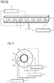
- FIG. 4 shows a sensor line schematically according to another configuration of the invention described herein;
- FIGS. 5 a and b show a sensor line schematically according to another configuration of the invention described herein;
- FIGS. 6 a and b show a coaxial cable schematically according to a configuration of the invention described herein.
- Configurations of the invention described herein comprise a sensor line with flexible capacitance.
- the invention comprises a cable structure that makes it possible to detect external influences on the cable and thus to represent a sensor line.
- the sensor line comprises (at least) one capacitor and (at least) two dielectrics.
- the change in the capacitance of the capacitor or capacitors can be used to detect loads on the sensor line. These loads can be mechanical (bending, torsion, lengthening (elongation/compression)), a medium intrusion and/or temperature-related.
- the second dielectric of the sensor line is compressive (i.e. compressible or extensible) relative to the first dielectric, wherein the second dielectric has a lower permittivity than the first dielectric.
- the second dielectric In the event of movements of the sensor line, (at least) the second dielectric is compressed or extended due to the movement. In a compression or extension of both dielectrics, the second dielectric is compressed or extended more strongly compared with the first dielectric.
- the total permittivity which is composed of the permittivities of the dielectrics, changes thereby. The change in the total permittivity causes a change in the capacitance of the capacitor or capacitors, which change can be measured.
- Conclusions can be drawn due to this about the mechanical influences on the sensor line. The greater the differences are in the relative permittivities of the dielectrics, the greater is the measurable effect.
- FIGS. 1 a to c show schematically a sensor line 100 according to one configuration of the invention described herein.
- the dielectric 1 is relatively rigid compared with dielectric 2 . Furthermore, in this example the dielectric 1 has a high relative permittivity compared with dielectric 2 .
- the dielectric 2 which is compressive (or more compressive) compared with dielectric 1 and has a lower relative permittivity, comprises air in this example.
- the sensor line 100 in this example comprises the capacitors 3 a (electrodes arranged top and bottom in the figure) and 3 b (electrodes arranged front and back in the figure).
- the capacitors 3 a and 3 b which are arranged here perpendicular to one another, make it possible to determine the direction of a bend (or torsion), in that the capacitances of the capacitors or their changes are compared with one another.
- the capacitance measurements can be carried out with the help of the apparatuses 5 .
- the arrows 4 indicate a change in area due to a temperature influence.
- the change in area has an influence on the capacitance of the capacitors 3 a and 3 b , which can be measured by the apparatuses 5 .
- Temperature effects can thus be measured by configurations of the sensor line.
- the area extension of the capacitor electrodes can be used in this case or a temperature-sensitive dielectric (or temperature-sensitive dielectrics) is/are used. Both cause a change in the measured capacitance.
- ⁇ 0 and d are constants in this case.
- a mechanical influence which can be caused by a bend, a torsion, a lengthening and/or a squashing (i.e. compression), affects the relative permittivity.
- a temperature influence can affect the effective electrode area and the relative permittivity.
- the change in the capacitance via the temperature influence usually takes place much more slowly than the change due to mechanical influences.
- the two influences can be separated from one another by suitable filtering, i.e. the slow offset behaviour of the temperature is separated from fast influences of the mechanics.
- the rigid dielectric remains (at least substantially) unchanged in its shape in the event of a bend in the sensor line.
- the dielectric 2 changes in this example in the event of a bend in such a way that its volume becomes smaller. This leads to a change in the permittivity and thus the measured capacitance.
- FIG. 1 c shows among other things a schematic cross section of the sensor line 100 . Due to the capacitance measurements by means of the apparatuses 5 a comparison can be made of the changes in capacitance, through which the bending direction can be determined.
- FIG. 2 a shows a structure in which the sensor line 200 has gaps 7 for a medium intrusion.
- the medium intrusion is represented schematically in FIG. 2 b by the arrow 8 .
- the medium intrusion through the gaps 7 causes the relative permittivity of the dielectric to change in a region in which the medium intrudes. This change can be determined in turn via the change in the capacitance.
- a dielectric can comprise a gas (for example, air) or gas mixture in this case, i.e. the sensor line consists of hollow chambers and the capacitors are configured so that a medium can penetrate from outside into these hollow chambers. The total permittivity changes due to the penetration of the medium.
- a gas for example, air
- gas mixture for example, air
- the sensor line 300 which is illustrated in FIGS. 3 a and b , differs from the sensor line 200 in FIGS. 2 a and b in that the dielectrics and the capacitors 3 a and 3 b assume round configurations in the sensor line 300 .
- the dielectric 2 (see FIG. 3 b ) consists in this example of air (i.e. hollow chambers), so that these can be filled by a medium.
- FIG. 4 shows among other things a sensor line 400 , in which three capacitors 3 a , 3 b and 3 c are used. A bend or a torsion of the sensor line or of the cable can be determined even more accurately due to the three capacitance measurements by means of the apparatuses 5 .
- FIGS. 5 a and b show schematically a sensor line 500 among other things, in which line a (relative to the dielectrics 2 a and 2 b ) rigid dielectric 1 , a (relative to the dielectric 1 ) flexible (i.e. compressive) dielectric 2 a with a (relative to dielectric 2 b ) high relative permittivity and a compressive dielectric 2 b with a low relative permittivity are used.
- the dielectric 2 b comprises air.
- the spiral winding of the dielectric 2 a around the dielectric 1 permits a relatively simple design of the sensor line 500 with the advantages described herein of the invention presented.
- any configurations of the sensor line that are described herein can be fitted in the interior of a cable.
- the cable as a whole can serve at the same time as a sensor line, i.e. a separate sensor line is thus dispensable.
- FIGS. 6 a and b show among other things a sensor line 600 , which is used as a coaxial cable.
- the sensor line 600 comprises an outer conductor 10 (electrode), an inner conductor 9 (electrode) and, as shown in FIG. 6 a , a flexible dielectric 2 a.
- the sensor line 600 comprises a flexible dielectric 2 a with a (relative to the dielectric 2 b ) high relative permittivity and a compressive dielectric 2 b with a (relative to the dielectric 2 a ) low relative permittivity.
- the dielectric 2 b comprises air.
- FIGS. 6 a and b thus makes it possible to detect external influences on the coaxial cable.
- the direction of a bend and/or the rotation direction of a torsion can also be determined.
- the method is based on the measurement of the change in capacitance of the line.
- Small capacitance changes can be measured by a broad spectrum of methods. These are, for example, the phase displacement in the case of a standing wave or the change in time of the charging/discharging behaviour for a square-wave voltage. The expert is familiar with these and other measuring methods.
Landscapes
- Physics & Mathematics (AREA)
- General Physics & Mathematics (AREA)
- Engineering & Computer Science (AREA)
- Power Engineering (AREA)
- Investigating Or Analyzing Materials By The Use Of Electric Means (AREA)
- Measurement Of Length, Angles, Or The Like Using Electric Or Magnetic Means (AREA)
Abstract
Description
C=ε 0×εr ×A/d,
where C is the capacitance of the capacitor, ε0 is the electric field constant, εr the relative permittivity, A the effective electrode area of the capacitor and d the electrode spacing.
Claims (15)
Applications Claiming Priority (3)
| Application Number | Priority Date | Filing Date | Title |
|---|---|---|---|
| DE102017212460.1 | 2017-07-20 | ||
| DE102017212460 | 2017-07-20 | ||
| DE102017212460.1A DE102017212460B4 (en) | 2017-07-20 | 2017-07-20 | SENSOR LINE |
Publications (2)
| Publication Number | Publication Date |
|---|---|
| US20190027275A1 US20190027275A1 (en) | 2019-01-24 |
| US10847284B2 true US10847284B2 (en) | 2020-11-24 |
Family
ID=64952029
Family Applications (1)
| Application Number | Title | Priority Date | Filing Date |
|---|---|---|---|
| US16/037,149 Expired - Fee Related US10847284B2 (en) | 2017-07-20 | 2018-07-17 | Sensor line |
Country Status (2)
| Country | Link |
|---|---|
| US (1) | US10847284B2 (en) |
| DE (1) | DE102017212460B4 (en) |
Families Citing this family (2)
| Publication number | Priority date | Publication date | Assignee | Title |
|---|---|---|---|---|
| DE102018204178B3 (en) | 2018-03-19 | 2019-09-12 | Leoni Kabel Gmbh | Coaxial line, measuring arrangement and method for measuring a torsion of a coaxial line |
| CN113470879B (en) * | 2021-07-16 | 2022-06-07 | 领迅电线工业(上海)有限公司 | Double-layer co-extrusion bending-resistant flame-retardant wire cable |
Citations (8)
| Publication number | Priority date | Publication date | Assignee | Title |
|---|---|---|---|---|
| US3565195A (en) | 1969-04-16 | 1971-02-23 | Sibany Mfg Corp | Electrical weighing apparatus using capacitive flexible mat |
| US4029889A (en) | 1974-10-08 | 1977-06-14 | Asahi Engineering & Construction Co., Ltd. | Fluid-leak detector cable |
| US7293467B2 (en) | 2001-07-09 | 2007-11-13 | Nartron Corporation | Anti-entrapment system |
| US20090099420A1 (en) * | 2007-10-11 | 2009-04-16 | Neoguide Systems, Inc. | System for managing bowden cables in articulating instruments |
| DE102009055426A1 (en) | 2009-12-30 | 2011-07-07 | Takata-Petri Ag, 63743 | Capacitive sensor module |
| US20120062245A1 (en) * | 2010-09-10 | 2012-03-15 | Zhenan Bao | Pressure Sensing Apparatuses and Methods |
| DE102013227051A1 (en) | 2013-12-20 | 2015-06-25 | Leoni Kabel Holding Gmbh | Measuring arrangement and method for temperature measurement and sensor cable for such a measuring arrangement |
| US20160033343A1 (en) * | 2014-08-01 | 2016-02-04 | The Board Of Trustees Of The Leland Stanford Junior University | Methods and apparatus concerning multi-tactile sensitive (e-skin) pressure sensors |
-
2017
- 2017-07-20 DE DE102017212460.1A patent/DE102017212460B4/en not_active Expired - Fee Related
-
2018
- 2018-07-17 US US16/037,149 patent/US10847284B2/en not_active Expired - Fee Related
Patent Citations (8)
| Publication number | Priority date | Publication date | Assignee | Title |
|---|---|---|---|---|
| US3565195A (en) | 1969-04-16 | 1971-02-23 | Sibany Mfg Corp | Electrical weighing apparatus using capacitive flexible mat |
| US4029889A (en) | 1974-10-08 | 1977-06-14 | Asahi Engineering & Construction Co., Ltd. | Fluid-leak detector cable |
| US7293467B2 (en) | 2001-07-09 | 2007-11-13 | Nartron Corporation | Anti-entrapment system |
| US20090099420A1 (en) * | 2007-10-11 | 2009-04-16 | Neoguide Systems, Inc. | System for managing bowden cables in articulating instruments |
| DE102009055426A1 (en) | 2009-12-30 | 2011-07-07 | Takata-Petri Ag, 63743 | Capacitive sensor module |
| US20120062245A1 (en) * | 2010-09-10 | 2012-03-15 | Zhenan Bao | Pressure Sensing Apparatuses and Methods |
| DE102013227051A1 (en) | 2013-12-20 | 2015-06-25 | Leoni Kabel Holding Gmbh | Measuring arrangement and method for temperature measurement and sensor cable for such a measuring arrangement |
| US20160033343A1 (en) * | 2014-08-01 | 2016-02-04 | The Board Of Trustees Of The Leland Stanford Junior University | Methods and apparatus concerning multi-tactile sensitive (e-skin) pressure sensors |
Non-Patent Citations (6)
| Title |
|---|
| Ferroelectric polymers, available at http://en.wikipedia.org/wiki/Ferroelectric_polymers on Mar. 6, 2017 (Year: 2017). * |
| M. I. A. Mokti, I. A. Rahim, A. A. Manaf, O. B. Sidek and M. A. B. Miskam, "Design and simulation of a MEMS capacitive bending strain sensor using dielectric materials for spinal fusion monitoring," 2011 IEEE Regional Symposium on Micro and Nano Electronics, Kota Kinabalu, 2011 (Year: 2011). * |
| P. D. Block and S. Bergbreiter, "Large area all-elastomer capacitive tactile arrays," Sensors, 2013 IEEE, Baltimore, MD, 2013, pp. 1-4 (Year: 2013). * |
| PVDF Material Information, available at http://www.goodfellow.com/E/Polyvinylidenefluoride.html on Jun. 21, 2020 (Year: 2020). * |
| R. Tang and Y. Huang, "Cable insulation detection based on coplanar capacitive sensor," May 2017 32nd Youth Academic Annual Conference of Chinese Association of Automation (YAC), Hefei, 2017, pp. 286-291 (Year: 2017). * |
| T. H. N. Dinh, P. Joubert, E. Martincic and E. Dufour-Gergam, "Flexible 3-axes capacitive pressure sensor array for medical applications," Sensors, 2014 IEEE, Valencia, 2014, pp. 855-858 (Year: 2014). * |
Also Published As
| Publication number | Publication date |
|---|---|
| DE102017212460B4 (en) | 2019-07-11 |
| US20190027275A1 (en) | 2019-01-24 |
| DE102017212460A1 (en) | 2019-01-24 |
Similar Documents
| Publication | Publication Date | Title |
|---|---|---|
| US10746584B2 (en) | Calibration-free continuous bin level sensor | |
| Terzic et al. | Capacitive sensing technology | |
| US10847284B2 (en) | Sensor line | |
| US4208909A (en) | Admittance sensing probe having multiple sensing elements | |
| CA3168409C (en) | Capacitive filling level probe without dead zone | |
| Chen et al. | Design of interdigital spiral and concentric capacitive sensors for materials evaluation | |
| US20170336242A1 (en) | Capacitive detection device and measuring device including same | |
| US11454609B2 (en) | Use of a solid fraction sensor to evaluate a solid fraction of a target pharmaceutical sample and solid fraction sensor | |
| EP3152558B1 (en) | Device and method for measuring condensation and/or advance of corrosion | |
| US20130261996A1 (en) | Self Calibrating Capacitive Fuel Sensor | |
| CN205102773U (en) | Simulation hole room is with inner wall deformation test device | |
| EP3684322B1 (en) | Pharmaceutical manufacturing installation and method of manufacturing of a pharmaceutical product | |
| CN112736306A (en) | Battery management chip and battery management system | |
| CN206756940U (en) | Capacitor type detects the probe apparatus of space permittivity | |
| DE10007188A1 (en) | Device for determining the level of a medium in a container | |
| KR102260386B1 (en) | Sensing device | |
| RU2332675C1 (en) | Method of polymeric systems dielectric characterisation | |
| Mahmood et al. | Calibration of Cross Capacitive Sensor used for Transformer Oil Testing | |
| US20120074964A1 (en) | Differential sand compaction sensor | |
| Hussain et al. | Detection of 2-FAL and moisture content in transformer oil using capacitive sensor | |
| SU343142A1 (en) | CAPACITIVE SENSOR FOR INSULATING INSULATING WIRES | |
| Bansod et al. | Performance evaluation of digital grain moisture analyser for Indian wheat | |
| US20230029571A1 (en) | Wet gas capacitance probe | |
| Parveen et al. | Transformer Oil Testing Using Comb Structured Capacitive Sensor | |
| RU2339936C1 (en) | Device for controlling moisture content of liquid fuel |
Legal Events
| Date | Code | Title | Description |
|---|---|---|---|
| AS | Assignment |
Owner name: LEONI KABEL GMBH, GERMANY Free format text: ASSIGNMENT OF ASSIGNORS INTEREST;ASSIGNOR:OELMANN, RICO;REEL/FRAME:046556/0673 Effective date: 20180705 |
|
| FEPP | Fee payment procedure |
Free format text: ENTITY STATUS SET TO UNDISCOUNTED (ORIGINAL EVENT CODE: BIG.); ENTITY STATUS OF PATENT OWNER: LARGE ENTITY |
|
| STPP | Information on status: patent application and granting procedure in general |
Free format text: DOCKETED NEW CASE - READY FOR EXAMINATION |
|
| STPP | Information on status: patent application and granting procedure in general |
Free format text: NON FINAL ACTION MAILED |
|
| AS | Assignment |
Owner name: LEONI KABEL GMBH, GERMANY Free format text: CHANGE OF ADDRESS OF ASSIGNEE;ASSIGNOR:LEONI KABEL GMBH;REEL/FRAME:053538/0166 Effective date: 20191216 |
|
| STPP | Information on status: patent application and granting procedure in general |
Free format text: RESPONSE TO NON-FINAL OFFICE ACTION ENTERED AND FORWARDED TO EXAMINER |
|
| ZAAA | Notice of allowance and fees due |
Free format text: ORIGINAL CODE: NOA |
|
| ZAAB | Notice of allowance mailed |
Free format text: ORIGINAL CODE: MN/=. |
|
| STPP | Information on status: patent application and granting procedure in general |
Free format text: PUBLICATIONS -- ISSUE FEE PAYMENT VERIFIED |
|
| STCF | Information on status: patent grant |
Free format text: PATENTED CASE |
|
| FEPP | Fee payment procedure |
Free format text: MAINTENANCE FEE REMINDER MAILED (ORIGINAL EVENT CODE: REM.); ENTITY STATUS OF PATENT OWNER: LARGE ENTITY |
|
| LAPS | Lapse for failure to pay maintenance fees |
Free format text: PATENT EXPIRED FOR FAILURE TO PAY MAINTENANCE FEES (ORIGINAL EVENT CODE: EXP.); ENTITY STATUS OF PATENT OWNER: LARGE ENTITY |
|
| STCH | Information on status: patent discontinuation |
Free format text: PATENT EXPIRED DUE TO NONPAYMENT OF MAINTENANCE FEES UNDER 37 CFR 1.362 |
|
| FP | Lapsed due to failure to pay maintenance fee |
Effective date: 20241124 |