US10845877B2 - Apparatus and method of forming localized vibration field, and method of disposing exciters - Google Patents
Apparatus and method of forming localized vibration field, and method of disposing exciters Download PDFInfo
- Publication number
- US10845877B2 US10845877B2 US15/139,735 US201615139735A US10845877B2 US 10845877 B2 US10845877 B2 US 10845877B2 US 201615139735 A US201615139735 A US 201615139735A US 10845877 B2 US10845877 B2 US 10845877B2
- Authority
- US
- United States
- Prior art keywords
- plate
- exciters
- local region
- vibration
- region
- Prior art date
- Legal status (The legal status is an assumption and is not a legal conclusion. Google has not performed a legal analysis and makes no representation as to the accuracy of the status listed.)
- Active
Links
Images


Classifications
-
- G—PHYSICS
- G06—COMPUTING OR CALCULATING; COUNTING
- G06F—ELECTRIC DIGITAL DATA PROCESSING
- G06F3/00—Input arrangements for transferring data to be processed into a form capable of being handled by the computer; Output arrangements for transferring data from processing unit to output unit, e.g. interface arrangements
- G06F3/01—Input arrangements or combined input and output arrangements for interaction between user and computer
- G06F3/016—Input arrangements with force or tactile feedback as computer generated output to the user
-
- H—ELECTRICITY
- H04—ELECTRIC COMMUNICATION TECHNIQUE
- H04R—LOUDSPEAKERS, MICROPHONES, GRAMOPHONE PICK-UPS OR LIKE ACOUSTIC ELECTROMECHANICAL TRANSDUCERS; ELECTRIC HEARING AIDS; PUBLIC ADDRESS SYSTEMS
- H04R17/00—Piezoelectric transducers; Electrostrictive transducers
- H04R17/10—Resonant transducers, i.e. adapted to produce maximum output at a predetermined frequency
-
- H—ELECTRICITY
- H04—ELECTRIC COMMUNICATION TECHNIQUE
- H04R—LOUDSPEAKERS, MICROPHONES, GRAMOPHONE PICK-UPS OR LIKE ACOUSTIC ELECTROMECHANICAL TRANSDUCERS; ELECTRIC HEARING AIDS; PUBLIC ADDRESS SYSTEMS
- H04R3/00—Circuits for transducers
- H04R3/12—Circuits for transducers for distributing signals to two or more loudspeakers
-
- H—ELECTRICITY
- H04—ELECTRIC COMMUNICATION TECHNIQUE
- H04R—LOUDSPEAKERS, MICROPHONES, GRAMOPHONE PICK-UPS OR LIKE ACOUSTIC ELECTROMECHANICAL TRANSDUCERS; ELECTRIC HEARING AIDS; PUBLIC ADDRESS SYSTEMS
- H04R17/00—Piezoelectric transducers; Electrostrictive transducers
-
- H—ELECTRICITY
- H04—ELECTRIC COMMUNICATION TECHNIQUE
- H04R—LOUDSPEAKERS, MICROPHONES, GRAMOPHONE PICK-UPS OR LIKE ACOUSTIC ELECTROMECHANICAL TRANSDUCERS; ELECTRIC HEARING AIDS; PUBLIC ADDRESS SYSTEMS
- H04R2201/00—Details of transducers, loudspeakers or microphones covered by H04R1/00 but not provided for in any of its subgroups
- H04R2201/40—Details of arrangements for obtaining desired directional characteristic by combining a number of identical transducers covered by H04R1/40 but not provided for in any of its subgroups
- H04R2201/401—2D or 3D arrays of transducers
-
- H—ELECTRICITY
- H04—ELECTRIC COMMUNICATION TECHNIQUE
- H04R—LOUDSPEAKERS, MICROPHONES, GRAMOPHONE PICK-UPS OR LIKE ACOUSTIC ELECTROMECHANICAL TRANSDUCERS; ELECTRIC HEARING AIDS; PUBLIC ADDRESS SYSTEMS
- H04R2400/00—Loudspeakers
- H04R2400/03—Transducers capable of generating both sound as well as tactile vibration, e.g. as used in cellular phones
-
- H—ELECTRICITY
- H04—ELECTRIC COMMUNICATION TECHNIQUE
- H04R—LOUDSPEAKERS, MICROPHONES, GRAMOPHONE PICK-UPS OR LIKE ACOUSTIC ELECTROMECHANICAL TRANSDUCERS; ELECTRIC HEARING AIDS; PUBLIC ADDRESS SYSTEMS
- H04R2499/00—Aspects covered by H04R or H04S not otherwise provided for in their subgroups
- H04R2499/10—General applications
- H04R2499/11—Transducers incorporated or for use in hand-held devices, e.g. mobile phones, PDA's, camera's
-
- H—ELECTRICITY
- H04—ELECTRIC COMMUNICATION TECHNIQUE
- H04R—LOUDSPEAKERS, MICROPHONES, GRAMOPHONE PICK-UPS OR LIKE ACOUSTIC ELECTROMECHANICAL TRANSDUCERS; ELECTRIC HEARING AIDS; PUBLIC ADDRESS SYSTEMS
- H04R7/00—Diaphragms for electromechanical transducers; Cones
- H04R7/02—Diaphragms for electromechanical transducers; Cones characterised by the construction
- H04R7/04—Plane diaphragms
Definitions
- the present disclosure relates to apparatuses and methods of forming a localized vibration field which form the localized vibration field on a plate by disposing exciters on the plate such as a display panel, and methods of disposing the exciters of the apparatuses for forming the localized vibration field.
- haptic sensation To implement haptic sensation at an electronic device such as a smartphone or a tablet personal computer (PC), various technologies are used.
- One of the most general technologies used for implementing haptic sensation is a spinning motor having an off-center weight which vibrates an entire electronic apparatus.
- this technology is used for implementing a sense of pressing a physical button/key. For example, when a user touches a button displayed on a touchscreen display, an entire electronic apparatus vibrates by rotating a motor for a short time.
- an electronic apparatus such as a smartphone or a tablet PC provides an image via a thin display panel having a small frame (or bezel) if possible. Due to a thin thickness and a small frame width of the apparatus, only small speakers may be mounted, but it is difficult to provide mid/low frequency sounds by using only the small speakers. Therefore, if an external sound apparatus is not separately connected, there are limitations in providing natural and affluent sounds by using only the apparatus.
- apparatuses for providing a vibration field pattern on a localized region of an appearance of an electronic apparatus are provided.
- apparatuses for forming a vibration field pattern that may feel haptic sensation on a local region of an appearance of an electronic apparatus.
- an apparatus for forming a localized vibration field includes: a plate; a plurality of exciters disposed at a plurality of locations in neighborhood of circumference of the plate and configured to excite the plate; and a driving controller configured to vibrate the plurality of exciters by using a substantially same excitation frequency, wherein the plurality of exciters excite a local region of the plate and suppress vibrations of a rest of regions except the local region of the plate.
- a method of forming a localized vibration field includes: disposing a plurality of exciters at a plurality of locations in neighborhood of circumference of a plate; and exciting the plate by vibrating the plurality of exciters with a substantially same excitation frequency, wherein the exciting of the plate includes exciting a local region of the plate and suppressing vibration of a rest of regions except the local region of the plate.
- a method of disposing exciters which vibrate a local region of a plate by exciting the plate at a plurality of locations in neighborhood of circumference of the plate includes: exciting a plurality of candidate locations in the neighborhood of the circumference of the plate by using a same excitation frequency; selecting relatively independent candidate locations with respect to localized vibration of the plate by calculating correlation between the localized vibration of the plate and vibrations at the plurality of candidate locations; and disposing the exciters at the selected independent candidate locations.
- An apparatus for forming a localized vibration field may form a vibration field pattern on a local region of an appearance of an electronic apparatus.
- An apparatus for forming a localized vibration field may allow haptic sensation to be felt on a local region of an appearance of an electronic apparatus.
- An apparatus for forming a localized vibration field may provide affluent sounds including frequencies in a mid range or a low range from among an audible frequency band to an electronic apparatus.
- a method of disposing exciters according to an embodiment may optimally dispose exciters forming a vibration field pattern on a local region of an appearance of an electronic apparatus.
- FIG. 1 is a view illustrating an appearance of an electronic apparatus that includes an apparatus for forming a localized vibration field according to an embodiment
- FIG. 2 is a view illustrating an apparatus for forming a localized vibration field according to an embodiment
- FIG. 3 is a flowchart for explaining a method of disposing exciters
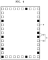
- FIG. 4 is a view illustrating independent locations from among a plurality of candidate locations of a plate
- FIG. 5 is a graph illustrating relation between a vibration velocity and a person's haptic recognition
- FIG. 6 is a diagram illustrating an operation of forming a localized vibration field at the apparatus for forming the localized vibration field of FIG. 2 ;
- FIGS. 7, 8, 9, and 10 are graphs illustrating implementation results of a localized vibration field formed by a method of forming a localized vibration field according to an embodiment
- FIGS. 11 and 12 are graphs illustrating implementation results of a localized vibration field formed by a method of forming a localized vibration field according to another embodiment
- FIGS. 13 and 14 are graphs illustrating implementation results of a localized vibration field formed by a method of forming a localized vibration field according to another embodiment
- FIG. 15 is a view illustrating an apparatus for forming a localized vibration field according to another embodiment
- FIGS. 16 and 17 are diagrams illustrating an operation of forming a localized vibration field at the apparatus for forming the localized vibration field of FIG. 15 ;
- FIGS. 18A and 18B are graphs illustrating amplitude and phase characteristics of a localized vibration field formed by the apparatus for forming the localized vibration field of FIG. 15 .
- FIG. 1 is a view illustrating an appearance of an electronic apparatus 10 that includes an apparatus 100 for forming a localized vibration field according to an embodiment
- FIG. 2 is a plan view illustrating the apparatus 100 for forming a localized vibration field according to an embodiment
- FIG. 3 is a flowchart for explaining a method of disposing exciters.
- the electronic apparatus 10 may be an information & communication technology (ICT) apparatus such as a smartphone or a tablet personal computer (PC). As illustrated in FIG. 1 , the electronic apparatus 10 may include a housing 11 and a display panel 12 .
- the housing 11 may have a plate shape.
- the display panel 12 may be located above one side of the housing 11 .
- the apparatus 100 for forming a localized vibration field may include a plate 110 , a plurality of exciters 120 , and a driving controller 190 .
- the plate 110 may include a material that may be excited.
- the plate 110 may be a portion of the electronic apparatus 10 described with reference to FIG. 1 .
- the plate 110 may be understood as the display panel 12 of the electronic apparatus 10 of FIG. 1 .
- the plate 110 may have a flat panel shape but is not limited thereto.
- the plate 110 may have a curved panel shape.
- the plurality of exciters 120 are disposed in the neighborhood of the circumference of the plate 110 and excite the plate 110 .
- the neighborhood of the circumference of the plate 110 denotes the outer boundary or its neighborhood of the plate 110 .
- the plurality of exciters 120 may be disposed on the backside of the display panel 12 of the electronic apparatus 10 described with reference to FIG. 1 .
- the plurality of exciters 120 may be disposed such that vibrations occur on local regions and vibrations are suppressed on the rest of regions when the plate 110 vibrates. That is, the plurality of exciters 120 form a vibration pattern so that haptic sensation is certainly felt only on portions touched by a hand or a specific region on the plate 110 .
- the plurality of exciters 120 may be disposed on only locations that independently contribute to the vibration field pattern. A method of disposing the plurality of exciters 120 is described below.
- the exciter 120 may be, for example, a piezoelectric element.
- the piezoelectric element is formed by disposing electrodes on an upper surface and a lower surface of a piezoelectric single crystal, and induces vibration from a thickness change of the piezoelectric single crystal in response to a signal voltage applied to the electrodes.
- the driving controller 190 drives the plurality of exciters 120 so that the exciters 120 vibrate at the substantially same excitation frequency.
- the excitation frequency may be selected within a frequency band in which haptic sensation by vibration is sensitive.
- the driving controller 190 may independently drive each of the plurality of exciters 120 such that amplitudes and phases of the plurality of exciters 120 are different from each other.
- the exciters 120 are disposed at a plurality of candidate locations S in the neighborhood of the circumference of the plate 110 first (S 210 ), and the exciters 120 are driven at the same excitation frequency (S 220 ).
- a transfer matrix may be obtained from relation between an electric input signal input to the exciters 120 and a velocity response at a measurement point by attaching thirty four small moving coil-type exciters 120 at the boundary of an reinforced glass panel P, and detecting a vibration velocity at seventy seven internal measurement points by using a laser Doppler Vibrometry (LDV).
- the reinforced glass panel P is used as the display panel 11 (see FIG. 1 ), and may be understood as the plate 110 according to an embodiment.
- An input signal of each exciter 120 required for control may be obtained by using an eigen-function expansion method or an inverse problem method via a bending traveling wave control.
- a transfer matrix between the exciters 120 and a vibration field used for the inverse problem may be decomposed by using singular value decomposition (SVD).
- the singular value decomposition decomposes an orthogonal square matrix into a diagonal matrix with an eigen value used as a basis by using a spectrum theory.
- relatively independent locations S 2 are selected with respect to localized vibration of the plate 110 by calculating correlation between the localized vibration of the plate 110 and vibrations at the plurality of candidate locations S (S 230 ).
- independence between the exciters 120 may be determined depending on a square value of a singular vector obtained via a singular value decomposition method.
- Excitation at the rest of locations S 1 except the independent locations S 2 may be derived via a combination of excitations at the independent locations S 2 .
- the eigen-function expansion method is described below.
- a response of a structure receiving external force may be expressed by configuring a mode variable representing a vibration characteristic of a system and using Equations 1 and 2 that use the eigen-function expansion as follows.
- n is the degree of a mode
- a i is weight of an l-th exciter 120
- ⁇ n is a norm of an n-th mode
- ⁇ n is an eigen frequency
- ⁇ n is an eigen function
- ⁇ n i is an eigen-function value at an excitation point
- the same vibration field for each mode is defined as ⁇ n .
- a response depending on a contribution degree for each mode may be expressed by Equations 3 and 4 by using orthogonality of eigen functions.
- B n ⁇ S ⁇ v ⁇ ( x , y ) ⁇ ⁇ n ⁇ ( x , y ) ⁇ ⁇ dS Equation ⁇ ⁇ 4
- W n is a contribution degree of an n-th mode.
- a contribution degree for each mode in an objective vibration field may be obtained by using Equations 3 and 4.
- a desired contribution degree for each mode may be implemented by giving appropriate weight of the exciter 120 to the exciters 120 including an array disposed on a boundary.
- a response in the case where N exciters 120 are used may be known from Equation 1, and Equation 5 may be obtained by using a contribution degree for each mode of a vibration field which aims at the response.
- a relation equation of weight of the exciter 120 and a contribution degree for each mode may be expressed in terms of a matrix equation, and weight that may obtain a vibration field, which is our object, may be obtained by Equations 6 and 7.
- a N ⁇ 1 ⁇ N ⁇ m ⁇ W m ⁇ 1 Equation 7
- A weight of the exciter 120
- W is a mode contribution degree
- ⁇ is a transfer matrix between A including modal information and W
- ⁇ is a pseudo-inverse matrix.
- Equation 8 When excitation occurs at a certain location inside a structure, a bending traveling wave propagates.
- N exciters 120 and response information measured at p measurement points therefrom are given, a matrix equation of Equation 8 may be expressed.
- a matrix G uses a frequency response function measured via experiment as a transfer matrix between an input signal of the exciter 120 and a velocity response.
- E is an input signal of the exciter 120
- V is a velocity matrix at a measurement point.
- An input signal E of the exciter 120 may be obtained via the inverse-problem technique by using a transfer matrix and an objective vibration field.
- E N ⁇ 1 G N ⁇ p ⁇ V p ⁇ 1 Equation 9
- a vibration field which approximates to a desired objective vibration field may be obtained by applying the Tikhonov normalizaiton method as in Equations 10 and 11 below.
- J [ V ⁇ GE F ] H [ V ⁇ GE F ]+ ⁇ F H E F Equation 10
- E F [ G H G+ ⁇ I ] ⁇ 1 G H V Equation 11
- J is a price function for taking into account input power
- E F is an input signal
- H is the Hermite operator.
- Weight ⁇ may be obtained by using a generalized cross validation (GCV) function. Through the normalization, it is revealed that power less than input power of the exciter 120 of the case where the normalization has not been performed may be used.
- GCV generalized cross validation
- an effective independent method (Efl) may be used. When this method is used, linearly independent relations of candidate groups of the exciters 120 disposed at different locations are known and optimized arrangement may be found.
- Equation 6 a transfer matrix ⁇ in Equation 6, which is a matrix equation including weight of the exciter 120 and a contribution degree for each mode
- Efl a linear independent value
- Equation 14 a decomposed Efl value is expressed by Equation 14.
- E f diag[ U n U n H ] Equation 14
- independence between the exciters 120 may be determined depending on the square magnitude of a singular vector obtained by Equation 14.
- a valid independent location is selected by removing a location of an exciter 120 having a smallest value, so that locations of most mutually independent exciters 120 with respect to a given number of the exciters 120 are optimally selected. Also, when an error is defined in advance, a minimum number and optimized arrangement of the exciters 120 required for forming a vibration field may be known.
- the apparatus 100 for forming a localized vibration field implements localization of vibration by using the plurality of exciters 120 disposed on the display panel 10 and the plate 110 of the electronic apparatus.
- an objective vibration field pattern is selected based on a frequency and an amplitude in which haptic sensation by vibration is most sensitive, vibration is generated in the form of standing waves, and also an object achievement degree factor of appraising implementation results accordingly may be used.
- locations of most mutual independent exciters 120 are optimally selected with respect to a given number of the exciters 120 , so that a minimum number and optimized arrangement of the exciters 120 required for forming a vibration field may be known.
- an objective vibration pattern generally including a vibration haptic sensation implementation region having a large amplitude and a non-vibration region having no haptic sensation and a small amplitude on the display panel 10
- a frequency, an amplitude, and/or a size of haptic sensation difference limen which take into account sensitivity of haptic sensation may be selected.
- an objective achievement degree regarding forming of a vibration haptic sensation implementation region and a non-vibration region having no haptic sensation may be made and used as an appraisal value by using the frequency, the amplitude, and/or the size of haptic sensation difference limen.
- FIG. 5 is a graph illustrating relation between a vibration velocity and a person's haptic recognition
- FIG. 6 is a diagram illustrating an operation of forming a localized vibration field at a plate.
- an objective vibration field pattern includes a vibration haptic sensation implementation region (referred to as a hot zone), where a strong vibration haptic sensation may be felt, and a non-vibration region having no haptic sensation (referred to as a cold zone), where haptic sensation is not felt by suppressing vibration.
- maximum energy of the cold zone may be allowed to have a difference of about 2 dB or more, which is a size of a difference limen, compared to a vibro-tactile threshold, and likewise, minimum energy of the hot zone may be allowed to have a difference of about 2 dB or more.
- the objective vibration field may be implemented as in FIG. 6 .
- the vibro-tactile threshold may change more or less depending on an excitation frequency.
- excitation may be performed by using a frequency in the neighborhood of about 300 Hz where a vibro-tactile threshold by vibration is minimum or a signal in a narrow band (for example, a signal in a band ranging from about 250 Hz to about 350 Hz) which uses such a frequency as a central frequency.
- a success ratio S for appraising a result of the objective vibration field based on haptic sensation information by vibration such as a threshold and a difference limen is defined as an achievement degree factor.
- FIGS. 7 to 10 illustrate implementation results of a localized vibration field in the case where an eigen-function expansion method is used as a method of forming a localized vibration field according to an embodiment.
- FIGS. 7 and 8 illustrate implementation results of a localized vibration field applied to 2 ⁇ 2 divided regions
- FIGS. 9 and 10 illustrate implementation results of a localized vibration field applied to 3 ⁇ 3 divided regions.
- a region in which a vibration velocity is less than about 0.2 mm/s corresponds to the cold zone in which vibration cannot be recognized.
- a region in which a vibration velocity is equal to or greater than about 0.2 mm/s corresponds to the hot zone.
- the velocity of about 0.2 mm/s may be understood as a vibro-tactile threshold. Referring to FIGS. 7 and 8 , it is known that the hot zone in which a vibration velocity is equal to or greater than about 0.2 mm/s is locally limited to a left upper region from among the 2 ⁇ 2 divided regions. In this case, the success ratio S is calculated as about 90.2%.
- a vibration velocity of about 0.4 mm/s or more may provide more definite vibration, and this hot zone, as illustrated in FIGS. 9 and 10 , may be locally limited in the 3 ⁇ 3 divided regions.
- a success ratio S is measured as about 86.5%.
- FIGS. 11 and 12 illustrate implementation results of a localized vibration field in the case where a bending traveling wave controllling method (normalizaiton not used) is used as a method of forming a localized vibration field according to an embodiment.
- FIG. 11 illustrates implementation results of a localized vibration field applied to 2 ⁇ 2 divided regions
- FIG. 12 illustrates implementation results of a localized vibration field applied to 3 ⁇ 3 divided regions.
- a success ratio S is measured as about 97.4%.
- a success ratio S is measured as about 98.7%.
- FIGS. 13 and 14 illustrate implementation results of a localized vibration field in the case where a bending traveling wave controllling method (normalizaiton not used) is used as a method of forming a localized vibration field according to another embodiment.
- FIG. 13 illustrate implementation results of a localized vibration field applied to 2 ⁇ 2 divided regions
- FIG. 14 illustrate implementation results of a localized vibration field applied to 3 ⁇ 3 divided regions. Referring to FIG. 13 , in the case where the localized vibration field is applied to the 2 ⁇ 2 divided regions, a success ratio S is measured as about 98.7%. Referring to FIG. 14 , in the case where the localized vibration field is applied to the 3 ⁇ 3 divided regions, a success ratio S is measured as about 98.7%.
- the apparatus 100 for forming a localized vibration field is prepared on the display panel 10 of an information & communication technology (ICT) apparatus
- the apparatus 100 for forming a localized vibration field is not limited thereto.
- a plurality of exciters 120 may be disposed on the circumference of the backside of the ICT apparatus (that is, the backside of the display panel 10 ).
- the plurality of exciters 120 may be installed on a plate having a predetermined area.
- FIG. 15 is a view illustrating an apparatus 300 for forming a localized vibration field according to another embodiment.
- the apparatus 300 for forming a localized vibration field may include a plate 310 , a plurality of exciters 320 , and a driving controller 390 .
- the plate 310 may include a material that may be excited.
- the plate 310 may be a portion of the electronic apparatus 10 described with reference to FIG. 1 .
- the plate 310 may be understood as the display panel 12 of the electronic apparatus 10 of FIG. 1 .
- the plate 110 may have a flat panel shape but is not limited thereto.
- the plate 310 may have a curved panel shape.
- the plurality of exciters 320 are disposed in the neighborhood of the circumference of the plate 310 and excite the plate 310 .
- the plurality of exciters 320 may be attached close to a boundary portion of the plate 310 to form a single closed curve and form a single exciter array.
- the plurality of exciters 320 may be attached on a boundary or locations very close to the boundary of the backside of the display panel 12 of the electronic apparatus described with reference to FIG. 1 such that an inner space is completely surrounded by the plurality of exciters 320 .
- the plurality of exciters 320 may be, for example, piezoelectric elements.
- the driving controller 390 drives the plurality of exciters 320 so that the plurality of exciters 320 vibrate at the substantially same excitation frequency.
- the driving controller 390 may drive each of the plurality of exciters 320 independently so that amplitudes and phases of the plurality of exciters 320 are different from each other.
- FIGS. 16 and 17 are diagrams illustrating an operation of forming a localized vibration field at the apparatus 300 for forming the localized vibration field.
- a single mode vibration in which a phase is constant is induced in a specific local sound source region to which sounds are to be radiated, and excitation is not allowed in the other regions.
- the cold zone may be understood as a baffle of a speaker.
- a sound source-forming region at the plate 110 may be generated at various locations via appropriate arrangement of the exciters 320 and an input signal like the embodiment described with reference to FIGS. 1 to 14 .
- FIGS. 18A and 18B are graphs illustrating amplitude and phase characteristics of a localized vibration field formed by the apparatus 300 for forming the localized vibration field according to an embodiment. Referring to FIG. 18A , it is known that vibration occurs only at a region A. Also, referring to FIG. 18B , it is known that the vibration at the region A has the same phase.
- a user may feel an effect as if sounds directly came out from the plate 310 by using the apparatus 300 for forming the localized vibration field according to an embodiment.
- a location S of a sound source inside the plate 310 may be changed by differing an input electric signal to the array of the exciters 320 . Since an additional speaker unit is not required, space efficiency improves.
- a limitation characteristic of a low frequency sound is determined by a size of a sound source. Since the apparatus 300 for forming the localized vibration field according to an embodiment uses a sound source of a wide region, mid/low frequency sounds, which have been difficult to provide due to apparatus structure arrangement in the related art, may be implemented.
- the apparatus 300 for forming the localized vibration field is applied to the display panel 12 of the electronic apparatus 10 , so that mid/low frequency sounds may be provided to a specific local region within the display panel 12 , and vibration generation is suppressed in the other regions. Therefore, sound radiation efficiency improves and distortion reduces and thus natural and excellent sounds may be provided to a user.
Landscapes
- Engineering & Computer Science (AREA)
- General Engineering & Computer Science (AREA)
- Physics & Mathematics (AREA)
- Theoretical Computer Science (AREA)
- Signal Processing (AREA)
- Acoustics & Sound (AREA)
- General Physics & Mathematics (AREA)
- Health & Medical Sciences (AREA)
- Otolaryngology (AREA)
- Human Computer Interaction (AREA)
- General Health & Medical Sciences (AREA)
- Apparatuses For Generation Of Mechanical Vibrations (AREA)
- User Interface Of Digital Computer (AREA)
Abstract
Description
ψm×N A N×1 W m×1, Equation 6
A N×1=ΨN×m † W m×1 Equation 7
G p×N E N×1 V p×1 Equation 8
E N×1 =G N×p † V p×1 Equation 9
J=[V−GE F]H[V−GE F]+βF H E F Equation 10
E F=[G H G+βI]−1 G H V Equation 11
E f=diag[ψ(ψHψ)−1ψ]
E f=diag[G(G H G)−1 G] Equation 13
E f=diag[U n U n H] Equation 14
Claims (15)
Priority Applications (1)
| Application Number | Priority Date | Filing Date | Title |
|---|---|---|---|
| US15/139,735 US10845877B2 (en) | 2015-04-27 | 2016-04-27 | Apparatus and method of forming localized vibration field, and method of disposing exciters |
Applications Claiming Priority (5)
| Application Number | Priority Date | Filing Date | Title |
|---|---|---|---|
| US201562153127P | 2015-04-27 | 2015-04-27 | |
| US201562153153P | 2015-04-27 | 2015-04-27 | |
| KR1020160042389A KR102631306B1 (en) | 2015-04-27 | 2016-04-06 | Apparatus and method of forming localized vibration, and method for arranging exicitors |
| KR10-2016-0042389 | 2016-04-06 | ||
| US15/139,735 US10845877B2 (en) | 2015-04-27 | 2016-04-27 | Apparatus and method of forming localized vibration field, and method of disposing exciters |
Publications (2)
| Publication Number | Publication Date |
|---|---|
| US20160313796A1 US20160313796A1 (en) | 2016-10-27 |
| US10845877B2 true US10845877B2 (en) | 2020-11-24 |
Family
ID=57146778
Family Applications (1)
| Application Number | Title | Priority Date | Filing Date |
|---|---|---|---|
| US15/139,735 Active US10845877B2 (en) | 2015-04-27 | 2016-04-27 | Apparatus and method of forming localized vibration field, and method of disposing exciters |
Country Status (1)
| Country | Link |
|---|---|
| US (1) | US10845877B2 (en) |
Families Citing this family (6)
| Publication number | Priority date | Publication date | Assignee | Title |
|---|---|---|---|---|
| JP6511486B2 (en) * | 2017-05-30 | 2019-05-15 | クラリオン株式会社 | Vibration generating device and vibration generating method |
| US11051112B2 (en) * | 2018-01-09 | 2021-06-29 | Cirrus Logic, Inc. | Multiple audio transducers driving a display to establish localized quiet zones |
| CN107995575A (en) * | 2018-01-15 | 2018-05-04 | 京东方科技集团股份有限公司 | Display panel, display device, and control method for display panel |
| JP2020042609A (en) * | 2018-09-12 | 2020-03-19 | 富士通コンポーネント株式会社 | Feel presentation device |
| CN114442796A (en) * | 2020-11-05 | 2022-05-06 | 上海艾为电子技术股份有限公司 | Vibration device, local vibration adjustment method thereof and electronic equipment |
| US12182328B2 (en) * | 2022-06-10 | 2024-12-31 | Afference Inc. | Wearable electronic device for inducing transient sensory events as user feedback |
Citations (27)
| Publication number | Priority date | Publication date | Assignee | Title |
|---|---|---|---|---|
| US4514599A (en) | 1980-12-19 | 1985-04-30 | Nissan Motor Company, Limited | Speaker for automotive vehicle audio system having a vehicle panel serving as sound-amplifying medium |
| US4551849A (en) | 1982-05-11 | 1985-11-05 | Nissan Motor Company, Limited | Vehicle panel speaker for automotive audio system utilizing part of a vehicle panel as a sound-producing medium |
| US5433211A (en) * | 1993-07-19 | 1995-07-18 | National Research Council Of Canada | Method and system for identifying vibrotactile perception thresholds of nerve endings with inconsistent subject response rejection |
| WO1999008479A1 (en) | 1997-08-05 | 1999-02-18 | New Transducers Limited | Sound radiating devices/systems |
| KR20010072042A (en) | 1998-07-29 | 2001-07-31 | 에이지마, 헨리 | Acoustic device using bending wave modes |
| EP0936842B1 (en) | 1995-09-25 | 2004-05-06 | New Transducers Limited | Piezo speaker for improved passenger cabin audio systems |
| US20050002537A1 (en) | 1998-07-03 | 2005-01-06 | New Transducers Limited | Resonant panel-form loudspeaker |
| US20070213645A1 (en) * | 2006-02-24 | 2007-09-13 | Jona Zumeris | System and method for surface acoustic wave treatment of medical devices |
| US20090141915A1 (en) | 2007-12-04 | 2009-06-04 | Samsung Electronics Co., Ltd. | Method and apparatus for focusing sound using array speaker |
| KR20090079292A (en) | 2008-01-17 | 2009-07-22 | 성균관대학교산학협력단 | Sound output system of wall-mounted flat panel display |
| US20110090167A1 (en) * | 2008-10-03 | 2011-04-21 | Nissha Printing Co., Ltd. | Touch Sensitive Device |
| KR20120014538A (en) | 2010-08-09 | 2012-02-17 | 광주과학기술원 | A tactile pattern display device and a method of generating a tactile pattern on a display |
| KR101125510B1 (en) | 2010-12-22 | 2012-03-21 | 한국기술교육대학교 산학협력단 | Vibrator in mobile device, controlling system and method of making local vibrating pattern of the vibrator |
| KR20120055179A (en) | 2010-11-23 | 2012-05-31 | 한국전자통신연구원 | Transparent acoustic pixel transducer in connection with display device and fabrication method thereof |
| US20120162113A1 (en) | 2010-12-28 | 2012-06-28 | Gwangju Institute Of Science And Technology | Locally Vibrating Haptic Apparatus, Method for Locally Vibrating Haptic Apparatus, Haptic Display Apparatus and Vibrating Panel Using the Same |
| KR20120074831A (en) | 2010-12-28 | 2012-07-06 | 엘지이노텍 주식회사 | Hapttic apparatus and method of partial vibration |
| KR20120075064A (en) | 2010-12-28 | 2012-07-06 | 엘지이노텍 주식회사 | Haptic display apparatus and vibrating panel having plurality of vibrating point |
| US20120183162A1 (en) | 2010-03-23 | 2012-07-19 | Dolby Laboratories Licensing Corporation | Techniques for Localized Perceptual Audio |
| US20120242593A1 (en) | 2011-03-23 | 2012-09-27 | Samsung Electro-Mechanics Co.,Ltd. | Piezoelectric vibration module and touch screen using the same |
| KR20120118675A (en) | 2011-04-19 | 2012-10-29 | 광주과학기술원 | Filter design method to localize vibration in a panel and method of localizing of vibration in a panel thereby |
| US20120313874A1 (en) * | 2011-06-07 | 2012-12-13 | Stmicroelectronics (Grenoble 2) Sas | Method of manufacturing a vibratory actuator for a touch panel with haptic feedback |
| US20130127755A1 (en) | 2011-11-18 | 2013-05-23 | Sentons Inc. | Localized haptic feedback |
| JP5225247B2 (en) | 2009-10-26 | 2013-07-03 | 京セラ株式会社 | Tactile transmission device and display device including the same |
| US8854340B2 (en) | 2010-09-01 | 2014-10-07 | Au Optronics Corp. | Touch device with force feedback function |
| KR20140125540A (en) | 2013-04-19 | 2014-10-29 | 엘지전자 주식회사 | Display apparatus and control method thereof |
| US20150003648A1 (en) | 2013-06-27 | 2015-01-01 | Samsung Electronics Co., Ltd. | Display apparatus and method for providing stereophonic sound service |
| US20150169058A1 (en) * | 2012-03-30 | 2015-06-18 | Nvf Tech Ltd | Touch and Haptics Device |
-
2016
- 2016-04-27 US US15/139,735 patent/US10845877B2/en active Active
Patent Citations (34)
| Publication number | Priority date | Publication date | Assignee | Title |
|---|---|---|---|---|
| US4514599A (en) | 1980-12-19 | 1985-04-30 | Nissan Motor Company, Limited | Speaker for automotive vehicle audio system having a vehicle panel serving as sound-amplifying medium |
| US4551849A (en) | 1982-05-11 | 1985-11-05 | Nissan Motor Company, Limited | Vehicle panel speaker for automotive audio system utilizing part of a vehicle panel as a sound-producing medium |
| US5433211A (en) * | 1993-07-19 | 1995-07-18 | National Research Council Of Canada | Method and system for identifying vibrotactile perception thresholds of nerve endings with inconsistent subject response rejection |
| EP0936842B1 (en) | 1995-09-25 | 2004-05-06 | New Transducers Limited | Piezo speaker for improved passenger cabin audio systems |
| WO1999008479A1 (en) | 1997-08-05 | 1999-02-18 | New Transducers Limited | Sound radiating devices/systems |
| JP2001513619A (en) | 1997-08-05 | 2001-09-04 | ニュー トランスデューサーズ リミテッド | Sound emitting device / system |
| US20050002537A1 (en) | 1998-07-03 | 2005-01-06 | New Transducers Limited | Resonant panel-form loudspeaker |
| KR20010072042A (en) | 1998-07-29 | 2001-07-31 | 에이지마, 헨리 | Acoustic device using bending wave modes |
| US20010019617A1 (en) | 1998-07-29 | 2001-09-06 | Denis Morecroft | Bending wave acoustic device |
| US20070213645A1 (en) * | 2006-02-24 | 2007-09-13 | Jona Zumeris | System and method for surface acoustic wave treatment of medical devices |
| US20090141915A1 (en) | 2007-12-04 | 2009-06-04 | Samsung Electronics Co., Ltd. | Method and apparatus for focusing sound using array speaker |
| KR20090058223A (en) | 2007-12-04 | 2009-06-09 | 삼성전자주식회사 | Method and apparatus for focusing sound through array speakers |
| KR20090079292A (en) | 2008-01-17 | 2009-07-22 | 성균관대학교산학협력단 | Sound output system of wall-mounted flat panel display |
| US20090196455A1 (en) | 2008-01-17 | 2009-08-06 | Sungkyunkwan University Foundation For Corporate Collaboration | Sound System of Wall Mounted Flat Panel Display Apparatus |
| US20110090167A1 (en) * | 2008-10-03 | 2011-04-21 | Nissha Printing Co., Ltd. | Touch Sensitive Device |
| JP5225247B2 (en) | 2009-10-26 | 2013-07-03 | 京セラ株式会社 | Tactile transmission device and display device including the same |
| US20120183162A1 (en) | 2010-03-23 | 2012-07-19 | Dolby Laboratories Licensing Corporation | Techniques for Localized Perceptual Audio |
| KR20120014538A (en) | 2010-08-09 | 2012-02-17 | 광주과학기술원 | A tactile pattern display device and a method of generating a tactile pattern on a display |
| US8854340B2 (en) | 2010-09-01 | 2014-10-07 | Au Optronics Corp. | Touch device with force feedback function |
| KR20120055179A (en) | 2010-11-23 | 2012-05-31 | 한국전자통신연구원 | Transparent acoustic pixel transducer in connection with display device and fabrication method thereof |
| KR101125510B1 (en) | 2010-12-22 | 2012-03-21 | 한국기술교육대학교 산학협력단 | Vibrator in mobile device, controlling system and method of making local vibrating pattern of the vibrator |
| KR20120074831A (en) | 2010-12-28 | 2012-07-06 | 엘지이노텍 주식회사 | Hapttic apparatus and method of partial vibration |
| KR20120075064A (en) | 2010-12-28 | 2012-07-06 | 엘지이노텍 주식회사 | Haptic display apparatus and vibrating panel having plurality of vibrating point |
| US20120162113A1 (en) | 2010-12-28 | 2012-06-28 | Gwangju Institute Of Science And Technology | Locally Vibrating Haptic Apparatus, Method for Locally Vibrating Haptic Apparatus, Haptic Display Apparatus and Vibrating Panel Using the Same |
| US20120242593A1 (en) | 2011-03-23 | 2012-09-27 | Samsung Electro-Mechanics Co.,Ltd. | Piezoelectric vibration module and touch screen using the same |
| KR20120108315A (en) | 2011-03-23 | 2012-10-05 | 삼성전기주식회사 | Piezoelectric vibration module and touch screen using the same |
| KR20120118675A (en) | 2011-04-19 | 2012-10-29 | 광주과학기술원 | Filter design method to localize vibration in a panel and method of localizing of vibration in a panel thereby |
| US20120313874A1 (en) * | 2011-06-07 | 2012-12-13 | Stmicroelectronics (Grenoble 2) Sas | Method of manufacturing a vibratory actuator for a touch panel with haptic feedback |
| US20130127755A1 (en) | 2011-11-18 | 2013-05-23 | Sentons Inc. | Localized haptic feedback |
| KR20140079488A (en) | 2011-11-18 | 2014-06-26 | 센톤스 아이엔씨. | Localized haptic feedback |
| US20150169058A1 (en) * | 2012-03-30 | 2015-06-18 | Nvf Tech Ltd | Touch and Haptics Device |
| KR20140125540A (en) | 2013-04-19 | 2014-10-29 | 엘지전자 주식회사 | Display apparatus and control method thereof |
| US20150003648A1 (en) | 2013-06-27 | 2015-01-01 | Samsung Electronics Co., Ltd. | Display apparatus and method for providing stereophonic sound service |
| KR20150001521A (en) | 2013-06-27 | 2015-01-06 | 삼성전자주식회사 | Display apparatus and method for providing a stereophonic sound service |
Non-Patent Citations (6)
| Title |
|---|
| J. C. Craig, "Difference Threshold for Intensity of Tactile Stimuli," Perception & Psychophysics, 1972, vol. 11, pp. 150-152. |
| J. H. Hyun, et al., "Mode-Superposition for Vibration Localization of Thin Plate", Proceedings of the Korean Society for Noise and Vibration Engineering, pp. 13-14, Gyeongju (2009). |
| L. Yao, et al., "Sensor Placement for On-Orbit Modal Identification of Large Space Structures via a Genetic Algorithm", 1992 IEEE, pp. 332-335. |
| M. R. Bai, et al., "Impact Localization Combined With Haptic Feedback for Touch Panel Applications Based on the Time-Reversal Approach," Journal of the Acoustical Society of America, vol. 129, No. 3, Mar. 2011, pp. 1297-1305. |
| M. S. Bai, et al., "Practical Implementation", Acoustic Array Systems: Theory, Implementation, and Application, John Wiley & Sons, Inc., Singapore, 2013, pp. 211-213. |
| S.J. Bolanowski, Jr., et al., "Four Channels Mediate the Mechanical Aspects of Touch," Journal of the Acoustical Society of America vol. 84, No. 5, Nov. 1988, pp. 1680-1694. |
Also Published As
| Publication number | Publication date |
|---|---|
| US20160313796A1 (en) | 2016-10-27 |
Similar Documents
| Publication | Publication Date | Title |
|---|---|---|
| US10845877B2 (en) | Apparatus and method of forming localized vibration field, and method of disposing exciters | |
| EP2227730B1 (en) | Touch-sensitive device | |
| US10108268B2 (en) | Touch sensitive device | |
| US9436284B2 (en) | Time-reversal tactile stimulation interface | |
| US6965678B2 (en) | Electronic article comprising loudspeaker and touch pad | |
| US10986446B2 (en) | Panel loudspeaker controller and a panel loudspeaker | |
| US11743657B2 (en) | Method, system and devices for selective modal control for vibrating structures | |
| JP6055612B2 (en) | Electronics | |
| KR20110130427A (en) | Touch sensing devices | |
| JP2007300426A (en) | Piezoelectric vibrator and piezoelectric vibration generator provided with the same | |
| US11307714B2 (en) | Areal device offering improved localized deformation | |
| Heilemann et al. | The evolution and design of flat-panel loudspeakers for audio reproduction | |
| JP5821241B2 (en) | Speaker device and electronic device | |
| EP3732897B1 (en) | Actuator for distributed mode loudspeaker with extended damper and systems including the same | |
| KR102631306B1 (en) | Apparatus and method of forming localized vibration, and method for arranging exicitors | |
| Wahid et al. | Estimation and measurement of effective line mobility on a non-deterministic thin plate excited by a piezoelectric patch | |
| JPH06161476A (en) | Super directional sound wave output device | |
| EP3510793B1 (en) | Speaker arrangement | |
| JP2014236292A (en) | Ultrasonic vibrator | |
| JP5943046B2 (en) | Speaker device and electronic device | |
| Kim et al. | Vibrotactile rendering for uniform sound power on haptic display with minimum number of actuators | |
| Taninaka et al. | Analysis of Ultrasound Radiation and Proposal of Design Criteria in Ultrasonic Haptic Display for Practical Applications | |
| KR20200053112A (en) | Electronic device and control method thereof |
Legal Events
| Date | Code | Title | Description |
|---|---|---|---|
| AS | Assignment |
Owner name: KOREA ADVANCED INSTITUTE OF SCIENCE AND TECHNOLOGY, KOREA, REPUBLIC OF Free format text: ASSIGNMENT OF ASSIGNORS INTEREST;ASSIGNORS:KIM, SUNG-JOO;IH, JEONG-GUON;KIM, JONG-BAE;AND OTHERS;REEL/FRAME:038394/0317 Effective date: 20160421 Owner name: SAMSUNG ELECTRONICS CO., LTD., KOREA, REPUBLIC OF Free format text: ASSIGNMENT OF ASSIGNORS INTEREST;ASSIGNORS:KIM, SUNG-JOO;IH, JEONG-GUON;KIM, JONG-BAE;AND OTHERS;REEL/FRAME:038394/0317 Effective date: 20160421 Owner name: KOREA ADVANCED INSTITUTE OF SCIENCE AND TECHNOLOGY Free format text: ASSIGNMENT OF ASSIGNORS INTEREST;ASSIGNORS:KIM, SUNG-JOO;IH, JEONG-GUON;KIM, JONG-BAE;AND OTHERS;REEL/FRAME:038394/0317 Effective date: 20160421 |
|
| STPP | Information on status: patent application and granting procedure in general |
Free format text: NON FINAL ACTION MAILED |
|
| STPP | Information on status: patent application and granting procedure in general |
Free format text: RESPONSE TO NON-FINAL OFFICE ACTION ENTERED AND FORWARDED TO EXAMINER |
|
| STPP | Information on status: patent application and granting procedure in general |
Free format text: FINAL REJECTION MAILED |
|
| STPP | Information on status: patent application and granting procedure in general |
Free format text: RESPONSE AFTER FINAL ACTION FORWARDED TO EXAMINER |
|
| STPP | Information on status: patent application and granting procedure in general |
Free format text: ADVISORY ACTION MAILED |
|
| STPP | Information on status: patent application and granting procedure in general |
Free format text: DOCKETED NEW CASE - READY FOR EXAMINATION |
|
| STPP | Information on status: patent application and granting procedure in general |
Free format text: NON FINAL ACTION MAILED |
|
| STCV | Information on status: appeal procedure |
Free format text: NOTICE OF APPEAL FILED |
|
| STPP | Information on status: patent application and granting procedure in general |
Free format text: NOTICE OF ALLOWANCE MAILED -- APPLICATION RECEIVED IN OFFICE OF PUBLICATIONS |
|
| STPP | Information on status: patent application and granting procedure in general |
Free format text: NOTICE OF ALLOWANCE MAILED -- APPLICATION RECEIVED IN OFFICE OF PUBLICATIONS |
|
| STPP | Information on status: patent application and granting procedure in general |
Free format text: PUBLICATIONS -- ISSUE FEE PAYMENT VERIFIED |
|
| STCF | Information on status: patent grant |
Free format text: PATENTED CASE |
|
| MAFP | Maintenance fee payment |
Free format text: PAYMENT OF MAINTENANCE FEE, 4TH YEAR, LARGE ENTITY (ORIGINAL EVENT CODE: M1551); ENTITY STATUS OF PATENT OWNER: LARGE ENTITY Year of fee payment: 4 |