US10845471B2 - Extrinsic static noise characterization and removal - Google Patents
Extrinsic static noise characterization and removal Download PDFInfo
- Publication number
- US10845471B2 US10845471B2 US16/066,403 US201616066403A US10845471B2 US 10845471 B2 US10845471 B2 US 10845471B2 US 201616066403 A US201616066403 A US 201616066403A US 10845471 B2 US10845471 B2 US 10845471B2
- Authority
- US
- United States
- Prior art keywords
- victim
- aggressor
- signal
- photosensitive element
- calibration
- Prior art date
- Legal status (The legal status is an assumption and is not a legal conclusion. Google has not performed a legal analysis and makes no representation as to the accuracy of the status listed.)
- Active, expires
Links
Images


Classifications
-
- G—PHYSICS
- G01—MEASURING; TESTING
- G01S—RADIO DIRECTION-FINDING; RADIO NAVIGATION; DETERMINING DISTANCE OR VELOCITY BY USE OF RADIO WAVES; LOCATING OR PRESENCE-DETECTING BY USE OF THE REFLECTION OR RERADIATION OF RADIO WAVES; ANALOGOUS ARRANGEMENTS USING OTHER WAVES
- G01S7/00—Details of systems according to groups G01S13/00, G01S15/00, G01S17/00
- G01S7/48—Details of systems according to groups G01S13/00, G01S15/00, G01S17/00 of systems according to group G01S17/00
- G01S7/497—Means for monitoring or calibrating
-
- G—PHYSICS
- G01—MEASURING; TESTING
- G01C—MEASURING DISTANCES, LEVELS OR BEARINGS; SURVEYING; NAVIGATION; GYROSCOPIC INSTRUMENTS; PHOTOGRAMMETRY OR VIDEOGRAMMETRY
- G01C3/00—Measuring distances in line of sight; Optical rangefinders
- G01C3/02—Details
- G01C3/06—Use of electric means to obtain final indication
- G01C3/08—Use of electric radiation detectors
-
- G—PHYSICS
- G01—MEASURING; TESTING
- G01S—RADIO DIRECTION-FINDING; RADIO NAVIGATION; DETERMINING DISTANCE OR VELOCITY BY USE OF RADIO WAVES; LOCATING OR PRESENCE-DETECTING BY USE OF THE REFLECTION OR RERADIATION OF RADIO WAVES; ANALOGOUS ARRANGEMENTS USING OTHER WAVES
- G01S17/00—Systems using the reflection or reradiation of electromagnetic waves other than radio waves, e.g. lidar systems
- G01S17/02—Systems using the reflection of electromagnetic waves other than radio waves
- G01S17/04—Systems determining the presence of a target
-
- G—PHYSICS
- G01—MEASURING; TESTING
- G01S—RADIO DIRECTION-FINDING; RADIO NAVIGATION; DETERMINING DISTANCE OR VELOCITY BY USE OF RADIO WAVES; LOCATING OR PRESENCE-DETECTING BY USE OF THE REFLECTION OR RERADIATION OF RADIO WAVES; ANALOGOUS ARRANGEMENTS USING OTHER WAVES
- G01S17/00—Systems using the reflection or reradiation of electromagnetic waves other than radio waves, e.g. lidar systems
- G01S17/02—Systems using the reflection of electromagnetic waves other than radio waves
- G01S17/06—Systems determining position data of a target
- G01S17/08—Systems determining position data of a target for measuring distance only
- G01S17/10—Systems determining position data of a target for measuring distance only using transmission of interrupted, pulse-modulated waves
-
- G—PHYSICS
- G01—MEASURING; TESTING
- G01S—RADIO DIRECTION-FINDING; RADIO NAVIGATION; DETERMINING DISTANCE OR VELOCITY BY USE OF RADIO WAVES; LOCATING OR PRESENCE-DETECTING BY USE OF THE REFLECTION OR RERADIATION OF RADIO WAVES; ANALOGOUS ARRANGEMENTS USING OTHER WAVES
- G01S7/00—Details of systems according to groups G01S13/00, G01S15/00, G01S17/00
- G01S7/48—Details of systems according to groups G01S13/00, G01S15/00, G01S17/00 of systems according to group G01S17/00
- G01S7/483—Details of pulse systems
- G01S7/486—Receivers
- G01S7/487—Extracting wanted echo signals, e.g. pulse detection
- G01S7/4876—Extracting wanted echo signals, e.g. pulse detection by removing unwanted signals
-
- G—PHYSICS
- G01—MEASURING; TESTING
- G01S—RADIO DIRECTION-FINDING; RADIO NAVIGATION; DETERMINING DISTANCE OR VELOCITY BY USE OF RADIO WAVES; LOCATING OR PRESENCE-DETECTING BY USE OF THE REFLECTION OR RERADIATION OF RADIO WAVES; ANALOGOUS ARRANGEMENTS USING OTHER WAVES
- G01S7/00—Details of systems according to groups G01S13/00, G01S15/00, G01S17/00
- G01S7/48—Details of systems according to groups G01S13/00, G01S15/00, G01S17/00 of systems according to group G01S17/00
- G01S7/491—Details of non-pulse systems
- G01S7/4912—Receivers
- G01S7/4913—Circuits for detection, sampling, integration or read-out
Definitions
- the present invention relates to the field of extrinsic static noise characterization and removal, more particularly in the context of time-of-flight sensors using full-waveform signals.
- Prior art optical range-finding sensors comprise a light source adapted to emit light pulses of short duration.
- Each emitted light pulse that is backscattered by the objects in the environment of the sensor is captured by a sensor comprising one or an array of photodiodes.
- the signal generated by each photodiode is amplified and digitalized, resulting in a numerical signal.
- Each sample of the numerical signal corresponds to the intensity of the backscattered light at a specific time. This numerical signal is often called full-waveform signal or trace. Knowing the speed of light and the point in time at which the light pulse has been emitted, it is possible to relate each sample of the trace to a distance.
- the intensity peaks present in the trace correspond to objects in the scene and the positions of the intensity peaks in the trace correspond to the distances between the sensor and the objects.
- crosstalk reduction in optical time-of-flight systems is crucial for obtaining accurate measurements.
- crosstalk may be caused by electrical or optical issues.
- Electrical crosstalk is usually caused by an undesirable Electro-Magnetic Field (EMF) generated by one or more aggressor source contaminating the signal of one or more victim photodiode victim.
- Optical crosstalk is usually caused by the effects of undesirable refraction and/or reflection of the light emitted by the optical range-finding sensor on the photodiode elements.
- the time-of-flight optical sensor has a plurality of synchronized photosensitive elements, at least some are positioned in proximity thereby allowing electromagnetic crosstalk caused by an aggressor photosensitive element to affect at least one victim photosensitive element.
- computer-implemented methods and systems for at least partially removing extrinsic static noise from data obtained by an optical time-of-flight sensor using full-waveform analysis.
- the method comprises finding a mathematical representation of the electromagnetic crosstalk present in victim calibration traces and caused by aggressor photosensitive element using aggressor calibration traces and victim calibration traces, determining a predetermined threshold for the amplitude of the aggressor calibration trace at which the electromagnetic crosstalk is present in the victim calibration traces, predicting the extrinsic static noise generated by the aggressor signal on the synchronized victim operation trace using the mathematical representation to generate a predicted crosstalk signal, removing the predicted crosstalk signal from the synchronized victim operation trace to output a denoised signal.
- the system comprises an identification and parameter estimation unit, a peak detection unit and a crosstalk prediction unit. An optional saturated summit completion unit can be provided.
- a computer-implemented method for at least partially removing extrinsic static noise from full-waveform data obtained using an optical time-of-flight sensor includes the following steps:
- the aggressor calibration traces and the victim calibration traces are obtained in a controlled environment wherein an amplitude of a calibration peak of the aggressor calibration traces is varied and no object is present in a field-of-view of the victim photosensitive element(s).
- the predetermined threshold corresponds to a minimum amplitude of the calibration peak of the aggressor calibration traces at which the electromagnetic crosstalk is present in the plurality of victim calibration traces.
- the operation trace is obtained in an uncontrolled environment wherein a shape of a detection peak of the operation trace is determined by a presence of an object in a field-of-view of the optical time-of-flight sensor during normal operation, the shape including an amplitude and a location of the detection peak.
- the method further comprises identifying the operation trace as being saturated and interpolating a peak value of the operation trace identified as saturated. In one embodiment, interpolating the peak value is performed using a fourth-order polynomial equation.
- the mathematical representation is a difference equation, wherein coefficients of the difference equation describe a shape of the plurality of victim calibration traces with respect to the plurality of aggressor calibration traces for each victim photosensitive element.
- finding the mathematical representation includes determining a cost function for the difference equation; calculating the coefficients by minimizing the cost function and the minimal value of the cost function; and comparing the minimal value of the cost function to a cost threshold.
- the difference equation is a linear time-invariant discrete equation.
- calculating the coefficients of the difference equation is performed using an optimization method.
- the optimization method comprises a Levenberg-Marquardt method.
- the mathematical representation is determined using a template.
- the template is weighted by the amplitude of the detection peak and aligned with a location of the detection peak.
- a system for at least partially removing extrinsic static noise from full-waveform data obtained using an optical time-of-flight sensor comprises an identification and parameter estimation unit, a peak detection unit and a crosstalk prediction unit.
- an optional saturated summit completion unit is provided.
- the identification and parameter estimation unit receives the aggressor and victim calibration traces from the sensor and outputs the mathematical representation and the predetermined threshold for the peak detection.
- the peak detection unit receives the operation traces from the sensor and the predetermined threshold from the identification and parameter estimation unit and outputs the aggressor signals whose peaks are greater than the threshold with their victim operation traces.
- the crosstalk prediction unit receives the mathematical representation from the identification and parameter estimation unit and the aggressor signal with its victim operation traces from the peak detection unit to predict and remove, at least partly, the extrinsic static noise generated by the aggressor signal on each victim operation trace.
- a denoised signal is outputted by the crosstalk prediction unit.
- an optional saturated summit completion unit is provided for interpolating a peak value of the operation trace identified as saturated by the peak detection unit.
- a computer-implemented method for at least partially removing extrinsic static noise from data obtained by an optical time-of-flight sensor using full-waveform analysis and comprising a plurality of photosensitive elements comprising use of at least one processor for: receiving a normal operation trace from a given one of the plurality of photosensitive elements and at least one neighbor trace from at least one neighbor photosensitive element; determining a peak value of the normal operation trace and comparing the peak value to a given threshold; identifying the normal operation trace as being an aggressor signal when the peak value is greater than the given threshold; determining a respective crosstalk caused by the aggressor signal in each one of the at least one neighbor trace, the respective crosstalk corresponding to a respective extrinsic static noise present in each one of the at least one neighbor trace; removing the respective crosstalk from each one of the at least one neighbor trace, thereby obtaining at least one denoised signal; and outputting the at least one denoised signal.
- a system for at least partially removing extrinsic static noise from data obtained by an optical time-of-flight sensor using full-waveform analysis and comprising a plurality of photosensitive elements comprising: a crosstalk determining module for: receiving a normal operation trace from a given one of the plurality of photosensitive elements and at least one neighbor trace from at least one neighbor photosensitive element; determining a peak value of the normal operation trace and comparing the peak value to a given threshold; identifying the normal operation trace as being an aggressor signal when the peak value is greater than the given threshold; and determining a respective crosstalk caused by the aggressor signal in each one of the at least one neighbor trace; and a denoising module for: removing the respective crosstalk from each one of the at least one neighbor trace, thereby obtaining at least one denoised signal; and outputting the at least one denoised signal.
- FIG. 1 is a block diagram illustrating an optical time-of-flight sensor using full-waveform analysis
- FIG. 2 is a flow chart illustrating example main steps of the calibration sub-method
- FIG. 3 shows difference equations describing the shapes and the amplitudes of the extrinsic static noise of the crosstalk signal induced by an aggressor signal in its victims, in accordance with an example embodiment
- FIG. 4 is a flow chart illustrating example main steps of the operation sub-method
- FIG. 5 is a flow chart illustrating a method for at least partially removing an extrinsic static noise from a trace, in accordance with an example embodiment
- FIG. 6 is an exemplary graph of the amplitude of an aggressor signal as a function of time
- FIG. 7 is a flow chart illustrating a method for detecting a peak in a trace, in accordance with an example embodiment
- FIG. 8 illustrates the interpolation of a peak of a saturated trace, in accordance with an example embodiment
- FIG. 9 illustrates a system for at least partially removing extrinsic static noise, in accordance with an example embodiment
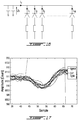
- FIG. 10 illustrates an array of photodiodes with their wire bounds
- FIG. 11 is a graph which illustrates the amplitude of a saturated aggressor pulse signal and two victim signals as a function of time, in accordance with an example embodiment
- FIG. 12 is a graph which illustrates an interpolated summit for the truncated aggressor signal of FIG. 11 , in accordance with an example embodiment
- FIG. 13 is an exemplary graph of the amplitude as a function of time for a measured trace and a corresponding simulated trace;
- FIG. 14 is an exemplary graph of the amplitude as a function of time for a victim signal prior to denoising and after denoising, in the case of crosstalk induced by an aggressor signal with adjacent wire bound;
- FIG. 15 is a graph which illustrates curves that correspond to the trace in the adjacent channels of the aggressor when the transverse position of the target in the aggressor channel is moved, in accordance with an example embodiment
- FIG. 16 illustrates an array of photodiode with single cathode wire bonding, in accordance with another embodiment
- FIG. 17 is an exemplary graph of the amplitude of an aggressor signal and its twelve victim signals in an example case of a single cathode wire bonding issue as a function of time;
- FIG. 18 illustrates a template for removing extrinsic static noise caused by a single cathode wire bounding in accordance with an example embodiment
- FIG. 19 is an exemplary graph of the amplitude of a victim signal prior to denoising and after denoising in the case of crosstalk induced by single cathode wire bounding as a function of time;
- the Signal-to-Noise Ratio (SNR) of a time-of-flight sensor using full waveform analysis is representative of its measurement accuracy and precision.
- Two main types of noise can have a negative impact on the SNR: the static noise and the random noise. Both of these causes the deterioration of the SNR.
- Static noise is the name given to a particular noise pattern in the photodiode signal which has a specific shape.
- the shape of the static noise can be time variant or time invariant. It can also depend on the operating conditions of the sensor. In the case of an optical system using full-waveform analysis, the static noise creates systematic errors on distance measurements of objects which may be lesser or greater than the correct value. The static noise typically degrades the accuracy of the sensor.
- Random noise is the term given to a random fluctuation in the trace.
- the random noise is due to different sources of noise such as thermal noise, dark noise, shot noise and ambient light. Contrary to the static noise, the random noise has a zero mean.
- This random noise variance may be attenuated using a simple low-pass filter or by averaging several traces of the same scene. In the case of an optical system based on full-waveform analysis, the random noise creates random errors on the distance measurements of objects. The random noise typically degrades the precision of the device.
- the static noise is usually caused by electromagnetic fields (EMFs) produced by multiple electronic sources, by light contaminations generated from multiple reflections and by refraction of the light emitted by the sensor.
- EMFs electromagnetic fields
- Two types of static noise can be distinguished, namely the intrinsic static noise and the extrinsic static noise.
- the extrinsic static noise is caused by the light backscattered by the object in the scene. It is produced by an optical pulse having a large amplitude.
- a large amplitude pulse, also called aggressor, received at a given photodiode creates various electric and electro-magnetic phenomena perturbing the operation of the photodiode(s) located in the neighborhood of the aggressor photodiode, called victim(s).
- the shape and the magnitude of the extrinsic static noise can be predicted from the shape and the magnitude of the aggressor pulse.
- extrinsic static noise is the case where a portion of the light received on a photodiode contained in a photodiode array may also be transmitted to another photodiode through the silicon layer installed to protect the photodiode array.
- a pulser 106 pulses an LED/Laser light source 108 at a substantially constant rate.
- a beam shaper 110 shapes the light beam emitted by the LED/Laser light source 108 in order to obtain a desired sensor field of emission.
- a portion of the pulses of light 134 sent into a detection zone is reflected back towards the optical time-of-flight sensor 100 as backscattered pulses 132 .
- a focalization lens 120 focalizes the signal backscattered by objects present in the detection zone on the photo-sensitive surface of the photodiode 122 .
- the focalization lens 120 is usually designed to match the sensor field of emission.
- Photodiode 122 converts the received photons into an electrical current.
- a TransImpedance Amplifier (TIA) 124 converts the variations of the electrical current passing through the photodiode 122 into a voltage.
- An Analog to Digital Converter (ADC) 126 converts the voltage outputted by the TIA 124 into a discrete number signal.
- a Field Programmable Gate Array (FPGA) 104 controls the pulser 106 as well as the acquisition of the photodiode signal from the ADC 126 .
- the generated pulses of light 134 are synchronized with the signal acquisition mechanism. It implements the oversampling and the accumulation principles which maximize the received Signal-to-Noise Ratio and increase the sampling resolution.
- Example processing aspects carried out by the signal acquisition mechanism and processor are described in U.S. Pat. No. 7,640,122, the contents of which is hereby incorporated by reference.
- the acquired signal is called a “trace”.
- a trace is a sequence of ADC samples. The value of each sample corresponds to the amount of LED/Laser light, also called count, received by the photodiode at a given time.
- the shape of the trace is determined by the shape, the distance and the reflectivity of the objects backscattering the light emitted by the sensor.
- the trace is actually a sum of the object reflections in the sensor field of emission.
- the peaks in the trace correspond to the reflections induced by the objects in the sensor field of emission.
- the reflections induced by the objects located close to the sensor will appear earlier in the trace while the reflections due to a further object will appear later.
- a microcontroller 102 synchronizes the operation of the components of the system. It also implements the signal processing algorithm that performs the static noise reduction and detects peaks in the trace in order to provide the distance of the detected objects 130 .
- the present method for characterizing and removing/attenuating the extrinsic static noise is described in the context of an optical system having a time-of-flight sensor using full-waveform analysis.
- the sensor comprises a plurality of photosensitive elements, such as photodiodes, located sufficiently close to one another to create crosstalk.
- the method for characterizing and attenuating the extrinsic static noise comprises two main steps.
- the first step is performed during the design of the sensor. This step consists in finding a mathematical representation of the extrinsic static noise generated in the victim signals.
- the victim signals are generated by victim photosensitive elements which are adjacent to a given aggressor photosensitive element and vary as a function of an aggressor signal received by the given aggressor photosensitive element.
- the aggressor receives an optical signal having a high amplitude, it generates an electric signal that creates crosstalk in the signals generated by at least some of its neighboring photosensitive elements.
- the signal generated by the aggressor is referred to as the aggressor signal, and the signal generated by a victim is referred to as a victim signal.
- the victim signal contains extrinsic static noise to be removed or at least attenuated.
- the second step is carried out during sensor operation.
- This method consists in predicting the extrinsic static noise generated by the aggressor based on the characterization of the photosensitive element generated during the identification step and in subtracting the predicted signal from the victim signals to improve their SNR ratio.
- the identification step also referred to as calibration sub-method 200 , illustrated in FIG. 2 , consists in finding the mathematical relation between a given aggressor signal and its victims. In order to do so, a plurality of aggressor signals with varying magnitude are generated on the photodiodes of the sensor. These are referred to as calibration traces 201 . They are used to identify 202 the photodiodes in which perturbations are induced. Once the aggressors and their victims are identified, the parameters of a model 204 that predicts the shape of the crosstalk generated by each aggressor in each victim is determined. These models are used to predict the shapes of the crosstalk signals generated by a given aggressor during the operation of sensor in order to at least attenuate the crosstalk present in its victims. The prediction model can take several forms, but difference equations or configurable templates are typically established 205 .
- the relation between an aggressor signal and its victims can be described by a difference equation such as a linear time-invariant discrete equation, as illustrated in FIG. 3 , where k is the trace samples, i is the aggressor photosensitive element, j is the victim photosensitive element, s a,i (k) is the aggressor signal in the photosensitive element i and s v,i,j is the perturbation induced by the aggressor i in the photosensitive element j.
- a,i (k) is the aggressor signal in the photosensitive element i
- s v,i,j is the perturbation induced by the aggressor i in the photosensitive element j.
- N is the order of the difference equation
- b and a are apriori unknown coefficients.
- the coefficients of the difference equation describing the shapes of the victims with respect to an aggressor signal are determined using experimental data. This process consists in finding the coefficients of Eq. 1 that minimize the squared difference between the victim signal predicted from the aggressor with the difference equation and the measured victim signal over several traces. The following steps are performed in order to determine the coefficients of the difference equation.
- An aggressor signal i is created in a given photodiode element of the sensor while adjacent photodiodes are obstructed. Several traces are captured while varying the amplitude of the aggressor signal.
- the l th measured aggressor signal is denoted ⁇ tilde over (s) ⁇ i (l,k).
- l th measured victim signal is denoted ⁇ tilde over (s) ⁇ i,j (l,k).
- an aggressor signal does not affect a given photosensitivity element in its neighborhood. In that case, the coefficients of the difference equation describing the relation between these elements are set to zero.
- E is the number of samples in a trace
- F is the number of acquired traces
- ⁇ tilde over (s) ⁇ i,j (l,k) is the k th sample of the l th acquired trace
- s i,j (l,k) is the k th sample of the victim signal predicted using the l th aggressor signal using Eq. 1.
- the relation between the aggressor and its victims cannot be expressed accurately using a difference equation.
- the phenomena causing the crosstalk may be too complex to be modelled using a simple linear time-invariant model.
- the number of difference-equation coefficients required to model the crosstalk is too high to allow a real-time implementation of the solution.
- the shape of the crosstalk signal is predicted using a template weighted by the maximum amplitude of the aggressor signal and aligned with the location of the maximum peak of the aggressor.
- the minimum value of the cost function used in the optimization problem presented in Eq. 2 is monitored and compared to a predefined threshold.
- the minimum value of the cost function is above the predefined threshold, the difference equation is considered not to be a reliable representation of the phenomenon occurring between the aggressor and the victims and a predefined template is used for modeling the relation between the aggressor and its victims. The following steps are performed to generate the noise template.
- An aggressor signal i is created in a given photodiode element of the sensor and F traces are captured while varying the amplitude of the aggressor signal.
- the l th measured aggressor signal is denoted ⁇ tilde over (s) ⁇ i (l,k).
- the l th measured victim signal is denoted ⁇ tilde over (s) ⁇ i,j (l,k).
- the template t i,j (k) is established by normalizing the victim traces and averaging the normalized traces of the victim as expressed in the following equation:
- u l and l l correspond respectively to the maximum and the minimum intensity value of l th trace of the victim signal.
- the gain A and the delay d between the position of the maximum peak of the aggressor and the template T i,j (k) that minimize the squared sum of the difference between the weighted/delayed template and the measured victims are determined.
- m i is the position of the maximum peak of the aggressor i evaluated using a quadratic interpolation of the aggressor summit.
- the difference equations or the templates describing the relations between the aggressor and the victim are established 205 , they are used to remove or at least attenuate the extrinsic static noise in the traces of the victims using the operation sub-method 210 illustrated in FIG. 4 .
- a plurality of operation traces 211 are generated on the photodiodes of the sensor. The shapes of the operation traces 211 are determined by the presence of objects in the field-of-view of the sensor.
- the attenuation/removal of the extrinsic static noise comprises the following steps.
- the first step 212 consists in detecting pulses in the trace of each photodiode element, as described below.
- the second step 214 which is optional, consists in completing the summit of any saturated pulses to remove the discontinuities in the trace of the aggressor, if any.
- the third step 216 consists in determining which ones of the detected pulses have an amplitude sufficient to generate crosstalk (that is, to be an aggressor) in other photodiode elements. If the amplitude is considered sufficient to generate crosstalk 218 , the last step consists 220 in attenuating/removing the crosstalk generated by each aggressor in the traces of each of its victims using either the difference equation or the crosstalk template established 205 during calibration.
- the cleaned photodiode traces or signals are outputted 221 .
- FIG. 5 illustrates one embodiment of a method 300 for at least partially removing extrinsic static noise in a signal obtained by an optical time-of-flight sensor using full-waveform analysis.
- the first step 302 consists in concurrently receiving the traces from the photosensitive elements.
- the peaks in each acquired trace are localized at step 304 .
- the summits of the saturated peaks, if any, are optionally completed using at step 306 .
- the values of the peaks found at the previous step are compared to a given threshold.
- the peaks with a maximum value higher than a given threshold are identified as aggressor peaks at step 310 .
- the victim traces of each aggressor peak are identified at step 312 .
- the crosstalk caused by each aggressor signal is then removed or at least attenuated from its victim traces at step 314 , thereby obtaining the denoised traces.
- the denoised signal is outputted at step 316 .
- each detected pulse i is characterized by the following parameters, namely an amplitude a i , the index of their right side limit r i , the index of the left side limit l i , and the index of their maximum peak m i .
- the peak detection method 320 is described in FIG. 7 .
- This method can be seen as a state machine that finds the local maxima in the trace. Once located and characterized by the parameters presented above, each local maximum corresponds to a peak. The peaks of high amplitude are considered as aggressors.
- the method starts at 322 by assuming that the first sample is potentially the left side limit of the first peak in the trace. The method also assumes that the first sample is located on the rising edge of this peak. Thereafter, the method verifies each sample of the trace one after the other until they have all been checked 340 . For each sample, the algorithm checks if one of the following three cases occurs.
- the left and right side limits of each detected pulse are readjusted so that they do not exceed a predefined distance (in samples) from the index of the pulse maximum. As described below, this consideration may help reducing the computational burden of the crosstalk removal algorithm.
- the crosstalk signals are directly linked to the aggressor signals.
- the aggressor signal When the aggressor signal is saturated, the response of the difference equation is erroneous or the position of its maximum peak is uncertain which creates difficulties in aligning the crosstalk template.
- the interpolation of the summit of the saturated peak allows mimicking the shape of the equivalent non-saturated signal and hence obtaining a more accurate prediction of the crosstalk signal.
- FIG. 8 illustrates a saturated summit with its interpolated summit completion.
- a, b, c, d and e are the coefficients of the interpolation polynomial.
- the number of coefficients of this polynomial equation has been chosen to include sufficient degrees of freedom to accommodate the following constraints.
- the polynomial equation passes through three points: the non-saturated sample before the saturation plateau, the non-saturated sample after the saturation plateau and a sample centered on the saturated plateau with a value corresponding to the amplitude of the pulse if it was not saturated (3 constraints).
- the expected amplitude of the saturated pulse is computed using an empirical equation that depends on the width of the saturation plateau. This equation is built with experimental data taken as follows. The light source of the sensor is set to its maximum intensity in order to obtain a strongly saturated signal from a highly reflective target installed close to the sensor. The width of the saturation is computed. The intensity of the light source is decreased until the saturation disappears.
- the amplitude of the saturated pulse can be extrapolated using a simple product rule. This exercise is repeated for many widths of the saturation plateau in order to formulate the empirical equation (polynomial equation or piecewise function) that relates the amplitude of the saturated pulse as a function of the width of the saturation plateau.
- the transition between the non-saturated samples of the pulse and the interpolated sample should be smooth.
- the derivative of the polynomial equation with respect to k should be equal to the derivative of the trace at the samples before and after the saturation plateau (2 constraints).
- k 1 0
- s 1 s ⁇ ( l i - 2 )
- ds 1 dk ds dk ⁇ ( l i - 2 )
- k 2 k 1 + k 3 2
- s 2 s ⁇ ( k 2 + l i - 2 )
- k 3 w + 4
- s 3 s ⁇ ( k 3 + l i - 2 )
- ds 3 dk ds dk ⁇ ( k 3 + l i - 2 )
- A, B, C and D are defined as follows:
- A s 2 - s 1 - ds 1 dk ⁇ k 2 x 2 2 Eq . ⁇ 20
- B ( s 3 - s 1 - ds 1 dk ⁇ k 3 ) k 3 2 Eq . ⁇ 21
- C ds 3 dk - ds 1 dk x 3 Eq . ⁇ 22
- D C - 2 ⁇ B k 3 Eq . ⁇ 23
- the aggressor selection function simply determines if a given pulse can generate crosstalk based on its amplitude. A pulse is considered an aggressor when its amplitude is greater that a predefined threshold. If the pulse of a given signal is below the predefined threshold, then the given signal is not considered an aggressor.
- the first technique consists in defining the difference equations describing the shape of the crosstalk generated on the victims as a function of the aggressor signal.
- the second technique consists in defining a template weighted and aligned using the amplitude and the position of the maximum peak of the aggressor signal.
- the calibration method predicts the shape of the crosstalk in the victims by using the difference equations or the crosstalk templates.
- the prediction of the crosstalk signal generated by an aggressor on a given segment using the difference equation simply consists in computing the responses of the difference equations to the aggressor signal.
- the prediction of the crosstalk signals using templates is more complex.
- the template is scaled by a factor proportional to the aggressor amplitude.
- the template is then aligned with the position of the maximum peak of the aggressor.
- An interpolation technique may be used to increase the performance of the crosstalk attenuation.
- the amplitude factor as well as the number of sample shift or subsample shift (for more precision) of the template have been identified during calibration.
- the predicted shapes of the crosstalk generated by an aggressor in the victim signals are subtracted. To speed-up the computation time, it is assumed that the aggressor only affects its victims between its left and right side index limits determined by the peak detector algorithm presented above.
- the overall computer-implemented method which includes the identification/calibration sub-method and the operation sub-method can be summarized as follows. It is a method for at least partially removing extrinsic static noise from full-waveform data obtained using an optical time-of-flight sensor.
- the sensor has a plurality of synchronized photosensitive elements, at least some are positioned in proximity thereby allowing electromagnetic crosstalk caused by an aggressor photosensitive element to affect at least one victim photosensitive element.
- the method includes the following steps:
- the aggressor calibration traces and the victim calibration traces are obtained in a controlled environment wherein an amplitude of a calibration peak of the aggressor calibration traces is varied and no object is present in a field-of-view of the victim photosensitive element(s).
- the predetermined threshold corresponds to a minimum amplitude of the calibration peak of the aggressor calibration traces at which the electromagnetic crosstalk is present in the plurality of victim calibration traces.
- the operation trace is obtained in an uncontrolled environment wherein a shape of a detection peak of the operation trace is determined by a presence of an object in a field-of-view of the optical time-of-flight sensor during normal operation, the shape including an amplitude and a location of the detection peak.
- the method further comprises identifying the operation trace as being saturated and interpolating a peak value of the operation trace identified as saturated. In one embodiment, interpolating the peak value is performed using a fourth-order polynomial equation.
- the mathematical representation is a difference equation, wherein coefficients of the difference equation describe a shape of the plurality of victim calibration traces with respect to the plurality of aggressor calibration traces for each victim photosensitive element.
- finding the mathematical representation includes determining a cost function for the difference equation; calculating the coefficients by minimizing the cost function and the minimal value of the cost function; and comparing the minimal value of the cost function to a cost threshold.
- the difference equation is a linear time-invariant discrete equation.
- calculating the coefficients of the difference equation is performed using an optimization method.
- the optimization method comprises a Levenberg-Marquardt method.
- the mathematical representation is determined using a template.
- the template is weighted by the amplitude of the detection peak and aligned with a location of the detection peak.
- the methods described above can be embodied as a system, an example of which is shown in FIG. 9 .
- the system 400 is for at least partially removing extrinsic static noise from full-waveform data obtained using an optical time-of-flight sensor.
- the optical time-of-flight sensor 402 has a plurality of synchronized photosensitive elements. At least some of the synchronized photosensitive elements are positioned in proximity thereby allowing electromagnetic crosstalk caused by an aggressor photosensitive element to affect at least one victim photosensitive element.
- the system comprises an identification and parameter estimation unit 404 , a peak detection unit 406 , a crosstalk prediction unit 410 and an optional saturated summit completion unit 408 .
- the identification and parameter estimation unit 404 receives the aggressor and victim calibration traces from the sensor 402 and outputs the mathematical representation and the predetermined threshold for the peak detection.
- the peak detection unit 406 receives the operation traces from the sensor 402 and the predetermined threshold from the identification and parameter estimation unit 404 and outputs the aggressor signals whose peaks are greater than the threshold with their victim operation traces.
- the crosstalk prediction unit 410 receives the mathematical representation from the identification and parameter estimation unit 404 and the aggressor signal with its victim operation traces from the peak detection unit 406 to predict and remove, at least partly, the extrinsic static noise generated by the aggressor signal on each victim operation trace. A denoised signal is outputted by the crosstalk prediction unit 410 .
- an optional saturated summit completion unit 408 is provided for interpolating a peak value of the operation trace identified as saturated by the peak detection unit 406 .
- the crosstalk prediction unit 410 carries out its prediction and removal for all operation peaks detected by the peak detection unit 406 in each aggressor operation traces and for all aggressor traces.
- a trace from one photodiode of an array can be, simultaneously, an aggressor to one or many other photodiodes and a victim of a plurality of other photodiodes acting as aggressors and all crosstalk contributions are addressed by the crosstalk prediction unit 410 to ensure that the system has considered all crosstalk sources prior to outputting the denoised signal.
- the identification and parameter estimation unit 404 , the peak detection unit 406 , the optional saturated summit completion 408 and the crosstalk prediction unit 410 are provided by at least one processing unit configured for executing their respective method steps. Memories and communications means are provided as required.
- FIG. 10 shows an example setup 500 in which a photodiode array chip 502 is provided on a PCB 504 .
- the chip 502 includes a plurality of photodiodes 506 a to 506 p , collectively referred to as photodiode array 506 having photodiodes 506 x .
- Each photodiode 506 x of the array is connected by a wire 508 x to a PCB track 510 x .
- Adjacent photodiodes are typically not connected to adjacent PCB tracks. For example, photodiode 506 c is adjacent to photodiode 506 b and photodiode 506 d .
- Photodiode 506 c is connected by wire 508 c to PCB track 510 c .
- PCB tracks 510 a and 510 e are adjacent to PBC track 510 b . If photodiode 506 c is determined to be an aggressor because of the amplitude of its operation trace, it will usually create crosstalk, or extrinsic static noise, on the signals of its adjacent photodiodes 506 b and 506 d (its immediate neighbors) and on the signals of photodiodes 506 a and 506 e which have adjacent PCB tracks.
- the victims of photodiode 506 c when it is considered an aggressor, will therefore include neighboring photodiodes 506 a , 506 b , 506 d and 506 e , which are all located in proximity to photodiode 506 c.
- adjacent wire bound crosstalk Crosstalk between adjacent Printed Circuit Board (PCB) tracks, referred to as adjacent wire bound crosstalk, is one of the most common problems observed with sensors using photodiode arrays. This type of crosstalk is dependent on the PCB design.
- the aggressor signal is the source of the EMF which radiates and contaminates surrounding tracks (victims).
- the victims of photodiode 506 c when it is considered an aggressor, due to adjacent wire bound crosstalk will therefore include photodiodes 506 a and 506 e.
- the first step consists in generating a signal on the aggressor photodiode while no object is present in the field of view of the victims.
- One way of controlling that no object is present in the field of view of the victim photodiodes is to mask or cover the photosensitive areas of the potential victims.
- Example generated signals are illustrated in FIG. 11 .
- the amplitude of the signal aggressor is then varied to ensure that only the amplitude of the victim varies as a function of the aggressor amplitude. In other words, there exists a static gain between the aggressor and victim shapes.
- the wide dynamic range of signal exceeds the input voltage range of the ADC.
- the signal is truncated at the maximum value that the ADC can convert.
- the saturated completion summit function is used to interpolate the summit of the saturated aggressor pulse in order to use all of the available signal range in the optimization algorithm, as illustrated in FIG. 12 .
- the value of the arrival function cost is lower than a convergence threshold, which means that the identified difference equation of the IIR filter adequately describes the shape of the crosstalk signal as a function of the aggressor pulse.
- FIG. 14 shows example resulting curves for a compensated victim signal.
- Crosstalk generated between adjacent photocells or photosensitive elements is now analyzed. This type of crosstalk is caused by results of electro-magnetic interferences occurring inside the Positive Intrinsic Negative (PIN) diode.
- PIN Positive Intrinsic Negative
- the victims of photodiode 506 c when it is considered an aggressor, due to the proximity of the cells will therefore include photodiodes 506 b and 506 d.
- the first step consists in generating an aggressor in a given photocell while adjacent photodiodes are masked in order to observe only the shape and the amplitude of the crosstalk signal.
- the amplitude of the signal aggressor is then varied on its entire range.
- the saturated completion summit function is used to interpolate the summit when the pulses are saturated.
- the number of difference equation coefficients is set to 3.
- the value of the function cost is never lower than the predefined threshold. Consequently, one concludes that the transfer function is too complex to be modelled using a simple time-invariant model or that the number of coefficients of the difference equation required to model the phenomena is too high.
- FIG. 15 An experimental study of the signals shows that the shape of adjacent photocells crosstalk is difficult to predict as a function of the aggressor pulse since its shape varies as a function of the position of the target in the aggressor photodiode element. This phenomenon is illustrated in FIG. 15 .
- the curves correspond to the trace in the adjacent channels of the aggressor when the position of the target in the aggressor channel is moved.
- the adjacent-photocell crosstalk signal passes from a shape corresponding to the second derivative of the aggressor signal to its first derivative while the target is moving inside the photocell.
- the signal is unpredictable since one of the independent variables that determines its shape (position of the object in the photocell) is not available.
- An adjacent-photocell crosstalk signal depends on the characteristics and structure of the photodiode array. Due to single cathode wire bounding, also known as common cathode, the current (I T ) through the cathode is the sum of the currents through each anode (I 1 . . . I 6 ). An example setup is illustrated in FIG. 16 . When several photodiodes are traversed by a strong signal, the total current through the photodiode creates a perturbation on the voltage of the capacitors (Uc) which affects the photodiodes.
- the first step is to generate an aggressor signal in a given photodiode while there is no object present in the field of view of the other photodiodes in order to determine which photodiode will be affected by the single cathode wire bounding crosstalk.
- One way to achieve this controlled environment is to mask the other photodiodes.
- FIG. 17 illustrates the photodiode signals affected by single cathode wire bounding crosstalk.
- single cathode wire bounding causes one aggressor to affect the other photodiodes sharing its cathode.
- the amplitude of the aggressor signal is varied on the entire possible range.
- the saturated completion summit function is used to interpolate the summit when the pulses are saturated.
- the number of difference equation coefficients is set to 3.
- the value of the function cost is never lower than a threshold.
- the amplitude of the victim signals depends on the amplitude of the aggressor signals:
- T is the adjacent photocell crosstalk template and d is the delay between the raw signal and the template.
- d is the delay between the raw signal and the template.
Landscapes
- Engineering & Computer Science (AREA)
- Physics & Mathematics (AREA)
- General Physics & Mathematics (AREA)
- Radar, Positioning & Navigation (AREA)
- Remote Sensing (AREA)
- Computer Networks & Wireless Communication (AREA)
- Electromagnetism (AREA)
- Photometry And Measurement Of Optical Pulse Characteristics (AREA)
- Materials For Photolithography (AREA)
- Optical Radar Systems And Details Thereof (AREA)
- Noise Elimination (AREA)
- Length Measuring Devices By Optical Means (AREA)
Abstract
Description
s i,j(k)=−a N-1,i,j s i,j(k−N−1)−a N-2,i,j s i,j(k−N−2)− . . . −a 1,i,j s i,j(k−1)+b N-1,i,j s i(k−N−1)+b N-2,i,j s i(k−N−2)+ . . . +b 1,i,j s i(k−1)+b 0,i,j s i(k) Eq. 1
{A,d}=argminΣl=0 f-1Σk=0 e-1(AT(k−m i −d)−{tilde over (s)} i,j(l,k))2 Eq. 4
s(k)=ak 4 +bk 3 +ck 2 +dk+e Eq. 5
s i,j(k)=0.5438*s i,j(k−3)−0.3781*s i,j(k−2)−1.9301*s i,j(k−1)−0.2289*s i(k−3)+0.1445*s i(k−2)+0.1442*s i(k−1)−0.0644*s i(k) Eq. 24
A=−2.2*s 1+133 Eq. 25
Claims (17)
Priority Applications (1)
| Application Number | Priority Date | Filing Date | Title |
|---|---|---|---|
| US16/066,403 US10845471B2 (en) | 2015-12-28 | 2016-12-23 | Extrinsic static noise characterization and removal |
Applications Claiming Priority (3)
| Application Number | Priority Date | Filing Date | Title |
|---|---|---|---|
| US201562271727P | 2015-12-28 | 2015-12-28 | |
| PCT/IB2016/057985 WO2017115258A1 (en) | 2015-12-28 | 2016-12-23 | Extrinsic static noise characterization and removal |
| US16/066,403 US10845471B2 (en) | 2015-12-28 | 2016-12-23 | Extrinsic static noise characterization and removal |
Publications (2)
| Publication Number | Publication Date |
|---|---|
| US20190004158A1 US20190004158A1 (en) | 2019-01-03 |
| US10845471B2 true US10845471B2 (en) | 2020-11-24 |
Family
ID=59224690
Family Applications (2)
| Application Number | Title | Priority Date | Filing Date |
|---|---|---|---|
| US16/066,404 Active 2037-09-11 US11035937B2 (en) | 2015-12-28 | 2016-12-22 | Intrinsic static noise characterization and removal |
| US16/066,403 Active 2037-10-15 US10845471B2 (en) | 2015-12-28 | 2016-12-23 | Extrinsic static noise characterization and removal |
Family Applications Before (1)
| Application Number | Title | Priority Date | Filing Date |
|---|---|---|---|
| US16/066,404 Active 2037-09-11 US11035937B2 (en) | 2015-12-28 | 2016-12-22 | Intrinsic static noise characterization and removal |
Country Status (4)
| Country | Link |
|---|---|
| US (2) | US11035937B2 (en) |
| EP (2) | EP3397986A4 (en) |
| CA (2) | CA3009722C (en) |
| WO (2) | WO2017115247A1 (en) |
Cited By (1)
| Publication number | Priority date | Publication date | Assignee | Title |
|---|---|---|---|---|
| US12566908B2 (en) | 2022-09-22 | 2026-03-03 | International Business Machines Corporation | Single corner mixed voltage noise impact on function analysis |
Families Citing this family (16)
| Publication number | Priority date | Publication date | Assignee | Title |
|---|---|---|---|---|
| SE1750159A1 (en) * | 2017-02-17 | 2018-08-18 | Fingerprint Cards Ab | Canceling out impairment data in fingerprint images |
| EP3367668B1 (en) * | 2017-02-24 | 2019-10-02 | Melexis Technologies NV | Noise reduction in sample and hold systems |
| EP3460509B1 (en) * | 2017-09-22 | 2024-12-11 | ams AG | Method for calibrating a time-of-flight system and time-of-flight system |
| US11353555B2 (en) | 2017-11-01 | 2022-06-07 | Luminar, Llc | Detector quench circuit for lidar system comprising a discrete transistor to draw a quench current to enable a drop in a reverse bias voltage applied to an avalanche photodiode |
| JP7109906B2 (en) * | 2017-11-14 | 2022-08-01 | シャープ株式会社 | Optical sensors and electronics |
| US10884101B2 (en) * | 2018-01-30 | 2021-01-05 | Motorola Mobility Llc | Crosstalk detection and compensation |
| US11100194B2 (en) | 2018-06-01 | 2021-08-24 | Blackberry Limited | Method and system for cargo sensing estimation |
| US11500074B2 (en) * | 2018-12-14 | 2022-11-15 | Beijing Voyager Technology Co., Ltd. | Light detection and ranging (LiDAR) with pulse equalizer |
| WO2020201452A1 (en) * | 2019-04-02 | 2020-10-08 | Ams International Ag | Method of measuring optical crosstalk in a time of flight sensor and corresponding time of flight sensor |
| WO2020206602A1 (en) * | 2019-04-09 | 2020-10-15 | 华为技术有限公司 | Distance measurement method, apparatus and device |
| JP2021021597A (en) * | 2019-07-25 | 2021-02-18 | 株式会社東芝 | Device and method for measuring distance |
| TWI734252B (en) * | 2019-11-08 | 2021-07-21 | 立積電子股份有限公司 | Radar and method of updating background components of echo signal for radar |
| EP3862782A1 (en) * | 2020-02-04 | 2021-08-11 | Infineon Technologies AG | Apparatus and method for correcting an input signal |
| US11228368B1 (en) | 2020-09-03 | 2022-01-18 | Microsoft Technology Licensing, Llc | Characterization of inter-channel crosstalk in an optical network |
| JP2022117173A (en) * | 2021-01-29 | 2022-08-10 | 株式会社トプコン | Optical rangefinder and distance calculation method |
| JP7623873B2 (en) * | 2021-03-30 | 2025-01-29 | 浜松ホトニクス株式会社 | Photodetection circuit and measuring device |
Citations (3)
| Publication number | Priority date | Publication date | Assignee | Title |
|---|---|---|---|---|
| US7640122B2 (en) * | 2007-11-07 | 2009-12-29 | Institut National D'optique | Digital signal processing in optical systems used for ranging applications |
| US20120154786A1 (en) | 2010-12-21 | 2012-06-21 | Sick Ag | Optoelectronic sensor and method for the detection and distance determination of objects |
| US20150124241A1 (en) | 2012-05-18 | 2015-05-07 | Andreas Eisele | Optical Distance Measurement Device with Calibration Device to take Cross-Talk into Account |
Family Cites Families (6)
| Publication number | Priority date | Publication date | Assignee | Title |
|---|---|---|---|---|
| US5892575A (en) * | 1996-05-10 | 1999-04-06 | Massachusetts Institute Of Technology | Method and apparatus for imaging a scene using a light detector operating in non-linear geiger-mode |
| US20060164533A1 (en) * | 2002-08-27 | 2006-07-27 | E-Phocus, Inc | Electronic image sensor |
| TWI333542B (en) | 2007-06-25 | 2010-11-21 | Asia Optical Co Inc | Laser rangefinder and method for digital signal processing thereof |
| US8643742B2 (en) * | 2010-10-15 | 2014-02-04 | Cisco Technology, Inc. | Crosstalk filter in a digital image processing pipeline |
| EP3056924B1 (en) * | 2013-10-11 | 2020-01-01 | Mitsubishi Electric Corporation | Wind measurement lidar device |
| US9772398B2 (en) * | 2014-06-26 | 2017-09-26 | Intersil Americas LLC | Optical proximity sensors with reconfigurable photodiode array |
-
2016
- 2016-12-22 WO PCT/IB2016/057957 patent/WO2017115247A1/en not_active Ceased
- 2016-12-22 CA CA3009722A patent/CA3009722C/en active Active
- 2016-12-22 US US16/066,404 patent/US11035937B2/en active Active
- 2016-12-22 EP EP16881362.4A patent/EP3397986A4/en active Pending
- 2016-12-23 WO PCT/IB2016/057985 patent/WO2017115258A1/en not_active Ceased
- 2016-12-23 EP EP16881364.0A patent/EP3397985B1/en active Active
- 2016-12-23 CA CA3009869A patent/CA3009869C/en active Active
- 2016-12-23 US US16/066,403 patent/US10845471B2/en active Active
Patent Citations (3)
| Publication number | Priority date | Publication date | Assignee | Title |
|---|---|---|---|---|
| US7640122B2 (en) * | 2007-11-07 | 2009-12-29 | Institut National D'optique | Digital signal processing in optical systems used for ranging applications |
| US20120154786A1 (en) | 2010-12-21 | 2012-06-21 | Sick Ag | Optoelectronic sensor and method for the detection and distance determination of objects |
| US20150124241A1 (en) | 2012-05-18 | 2015-05-07 | Andreas Eisele | Optical Distance Measurement Device with Calibration Device to take Cross-Talk into Account |
Cited By (1)
| Publication number | Priority date | Publication date | Assignee | Title |
|---|---|---|---|---|
| US12566908B2 (en) | 2022-09-22 | 2026-03-03 | International Business Machines Corporation | Single corner mixed voltage noise impact on function analysis |
Also Published As
| Publication number | Publication date |
|---|---|
| CA3009722C (en) | 2021-01-26 |
| EP3397985A4 (en) | 2019-08-14 |
| CA3009869A1 (en) | 2017-07-06 |
| US20190011543A1 (en) | 2019-01-10 |
| EP3397985A1 (en) | 2018-11-07 |
| US20190004158A1 (en) | 2019-01-03 |
| WO2017115247A1 (en) | 2017-07-06 |
| EP3397986A1 (en) | 2018-11-07 |
| CA3009722A1 (en) | 2017-07-06 |
| CA3009869C (en) | 2018-11-27 |
| US11035937B2 (en) | 2021-06-15 |
| EP3397985B1 (en) | 2020-08-26 |
| WO2017115258A1 (en) | 2017-07-06 |
| EP3397986A4 (en) | 2019-08-07 |
Similar Documents
| Publication | Publication Date | Title |
|---|---|---|
| US10845471B2 (en) | Extrinsic static noise characterization and removal | |
| US12367257B2 (en) | Method and apparatus for processing a histogram output from a detector sensor | |
| CN111868561B (en) | Effective signal detection using adaptive identification of the noise floor | |
| CN113661407A (en) | Method for measuring optical crosstalk in a time-of-flight sensor and corresponding time-of-flight sensor | |
| EP3370080B1 (en) | Range and parameter extraction using processed histograms generated from a time of flight sensor - parameter extraction | |
| US20220128658A1 (en) | Waveform reconstruction in a time-of-flight sensor | |
| EP3370078A1 (en) | Range and parameter extraction using processed histograms generated from a time of flight sensor - crosstalk correction | |
| EP3370079B1 (en) | Range and parameter extraction using processed histograms generated from a time of flight sensor - pulse detection | |
| US11808895B2 (en) | Methods and devices for crosstalk compensation | |
| KR20210153563A (en) | System and method for histogram binning for depth detectiion | |
| EP3370086A1 (en) | Range and parameter extraction using processed histograms generated from a time of flight sensor - pile up correction | |
| EP4081823B1 (en) | Time of flight sensor | |
| CN113614566A (en) | Distance measurement method, distance measurement device, and program | |
| CN119439135A (en) | A data quality control method for wind laser radar | |
| CN113900113A (en) | TOF sensing device and distance detection method thereof | |
| Fasolino et al. | Real-time crosstalk compensation in multizone Time-of-Flight sensors | |
| JPH11133080A (en) | Electromagnetic interference measuring device | |
| US7039573B2 (en) | Method of formulating load model for glitch analysis and recording medium with the method recorded thereon | |
| Bekhtin et al. | Compensation of IR-sensor Fixed Pattern Noise during Point Object Magnitude Recovering | |
| TW202605406A (en) | Tof optical sensor calibration method and tof optical sensor calibration system | |
| KR20250133001A (en) | LiDAR NOISE CANCELING DEVICE | |
| CN119270289A (en) | Time-of-flight rising edge adaptive crosstalk correction | |
| Basden et al. | Low readout noise CCDs in optical interferometry | |
| CN121522652A (en) | A pulsed laser ranging method and system based on reverse overshoot suppression | |
| CN121703791A (en) | A method, device, and lidar for filtering out dirt and noise from light windows. |
Legal Events
| Date | Code | Title | Description |
|---|---|---|---|
| FEPP | Fee payment procedure |
Free format text: ENTITY STATUS SET TO UNDISCOUNTED (ORIGINAL EVENT CODE: BIG.); ENTITY STATUS OF PATENT OWNER: SMALL ENTITY |
|
| AS | Assignment |
Owner name: LEDDARTECH INC., CANADA Free format text: ASSIGNMENT OF ASSIGNORS INTEREST;ASSIGNORS:SIMARD-BILODEAU, VINCENT;GIDEL, SAMUEL;SIGNING DATES FROM 20170425 TO 20170426;REEL/FRAME:046489/0337 |
|
| FEPP | Fee payment procedure |
Free format text: ENTITY STATUS SET TO SMALL (ORIGINAL EVENT CODE: SMAL); ENTITY STATUS OF PATENT OWNER: SMALL ENTITY |
|
| STPP | Information on status: patent application and granting procedure in general |
Free format text: APPLICATION DISPATCHED FROM PREEXAM, NOT YET DOCKETED |
|
| STPP | Information on status: patent application and granting procedure in general |
Free format text: DOCKETED NEW CASE - READY FOR EXAMINATION |
|
| AS | Assignment |
Owner name: INVESTISSEMENT QUEBEC, CANADA Free format text: SECURITY INTEREST;ASSIGNOR:LEDDARTECH INC.;REEL/FRAME:051713/0622 Effective date: 20200130 |
|
| STPP | Information on status: patent application and granting procedure in general |
Free format text: NOTICE OF ALLOWANCE MAILED -- APPLICATION RECEIVED IN OFFICE OF PUBLICATIONS |
|
| STPP | Information on status: patent application and granting procedure in general |
Free format text: NOTICE OF ALLOWANCE MAILED -- APPLICATION RECEIVED IN OFFICE OF PUBLICATIONS |
|
| AS | Assignment |
Owner name: FEDERATION DES CAISSES DESJARDINS DU QUEBEC, QUEBEC Free format text: SECURITY CONFIRMATION AGREEMENT;ASSIGNOR:LEDDARTECH INC.;REEL/FRAME:053980/0942 Effective date: 20200123 |
|
| STPP | Information on status: patent application and granting procedure in general |
Free format text: PUBLICATIONS -- ISSUE FEE PAYMENT RECEIVED |
|
| STCF | Information on status: patent grant |
Free format text: PATENTED CASE |
|
| AS | Assignment |
Owner name: INVESTISSEMENT QUEBEC, CANADA Free format text: SECURITY INTEREST;ASSIGNOR:LEDDARTECH INC.;REEL/FRAME:055244/0208 Effective date: 20210205 |
|
| AS | Assignment |
Owner name: FEDERATION DES CAISSES DESJARDINS DU QUEBEC, CANADA Free format text: SECURITY INTEREST;ASSIGNOR:LEDDARTECH INC.;REEL/FRAME:063316/0716 Effective date: 20230405 |
|
| AS | Assignment |
Owner name: TSX TRUST COMPANY, CANADA Free format text: SECURITY INTEREST;ASSIGNOR:LEDDARTECH INC.;REEL/FRAME:063965/0233 Effective date: 20230609 |
|
| MAFP | Maintenance fee payment |
Free format text: PAYMENT OF MAINTENANCE FEE, 4TH YR, SMALL ENTITY (ORIGINAL EVENT CODE: M2551); ENTITY STATUS OF PATENT OWNER: SMALL ENTITY Year of fee payment: 4 |