US10842385B2 - Vascular impedance measuring device and method of determining impedance - Google Patents
Vascular impedance measuring device and method of determining impedance Download PDFInfo
- Publication number
- US10842385B2 US10842385B2 US15/316,018 US201515316018A US10842385B2 US 10842385 B2 US10842385 B2 US 10842385B2 US 201515316018 A US201515316018 A US 201515316018A US 10842385 B2 US10842385 B2 US 10842385B2
- Authority
- US
- United States
- Prior art keywords
- component
- pressure
- measuring device
- flow
- vascular impedance
- Prior art date
- Legal status (The legal status is an assumption and is not a legal conclusion. Google has not performed a legal analysis and makes no representation as to the accuracy of the status listed.)
- Expired - Fee Related, expires
Links
- 230000002792 vascular Effects 0.000 title claims abstract description 43
- 238000000034 method Methods 0.000 title claims abstract description 24
- 238000012545 processing Methods 0.000 claims abstract description 55
- 238000002560 therapeutic procedure Methods 0.000 claims abstract description 7
- 230000008569 process Effects 0.000 claims abstract description 3
- 239000003814 drug Substances 0.000 claims description 7
- 238000001361 intraarterial administration Methods 0.000 claims description 7
- 229940079593 drug Drugs 0.000 claims description 6
- 230000036772 blood pressure Effects 0.000 claims description 4
- 230000001225 therapeutic effect Effects 0.000 claims description 4
- 230000017531 blood circulation Effects 0.000 claims description 3
- 230000001902 propagating effect Effects 0.000 claims description 2
- 238000002642 intravenous therapy Methods 0.000 claims 1
- 210000001367 artery Anatomy 0.000 description 11
- 210000004004 carotid artery internal Anatomy 0.000 description 10
- 208000001286 intracranial vasospasm Diseases 0.000 description 9
- 238000012544 monitoring process Methods 0.000 description 8
- 238000005259 measurement Methods 0.000 description 7
- 238000002604 ultrasonography Methods 0.000 description 7
- 206010047163 Vasospasm Diseases 0.000 description 6
- 239000000523 sample Substances 0.000 description 6
- 238000001514 detection method Methods 0.000 description 5
- 238000000926 separation method Methods 0.000 description 5
- 208000031481 Pathologic Constriction Diseases 0.000 description 4
- 208000032851 Subarachnoid Hemorrhage Diseases 0.000 description 4
- 238000004458 analytical method Methods 0.000 description 4
- 210000002254 renal artery Anatomy 0.000 description 4
- 208000037804 stenosis Diseases 0.000 description 4
- 230000036262 stenosis Effects 0.000 description 4
- 210000005166 vasculature Anatomy 0.000 description 4
- 239000008280 blood Substances 0.000 description 3
- 210000004369 blood Anatomy 0.000 description 3
- 238000004364 calculation method Methods 0.000 description 3
- 230000000747 cardiac effect Effects 0.000 description 3
- 238000013480 data collection Methods 0.000 description 3
- 238000010586 diagram Methods 0.000 description 3
- 210000003734 kidney Anatomy 0.000 description 3
- 230000007246 mechanism Effects 0.000 description 3
- 210000002321 radial artery Anatomy 0.000 description 3
- 241000124008 Mammalia Species 0.000 description 2
- 208000006011 Stroke Diseases 0.000 description 2
- 230000008901 benefit Effects 0.000 description 2
- 210000004556 brain Anatomy 0.000 description 2
- 210000001168 carotid artery common Anatomy 0.000 description 2
- 238000012512 characterization method Methods 0.000 description 2
- 238000007405 data analysis Methods 0.000 description 2
- 238000009795 derivation Methods 0.000 description 2
- 201000010099 disease Diseases 0.000 description 2
- 208000037265 diseases, disorders, signs and symptoms Diseases 0.000 description 2
- 230000008030 elimination Effects 0.000 description 2
- 238000003379 elimination reaction Methods 0.000 description 2
- 238000007917 intracranial administration Methods 0.000 description 2
- 238000012546 transfer Methods 0.000 description 2
- 206010060965 Arterial stenosis Diseases 0.000 description 1
- 201000006474 Brain Ischemia Diseases 0.000 description 1
- 206010008120 Cerebral ischaemia Diseases 0.000 description 1
- 208000032843 Hemorrhage Diseases 0.000 description 1
- 208000004531 Renal Artery Obstruction Diseases 0.000 description 1
- 206010049739 Renal artery fibromuscular dysplasia Diseases 0.000 description 1
- 206010038378 Renal artery stenosis Diseases 0.000 description 1
- 210000000709 aorta Anatomy 0.000 description 1
- 230000008081 blood perfusion Effects 0.000 description 1
- 238000009530 blood pressure measurement Methods 0.000 description 1
- 210000001715 carotid artery Anatomy 0.000 description 1
- 210000000269 carotid artery external Anatomy 0.000 description 1
- 210000001627 cerebral artery Anatomy 0.000 description 1
- 206010008118 cerebral infarction Diseases 0.000 description 1
- 239000000812 cholinergic antagonist Substances 0.000 description 1
- 210000004351 coronary vessel Anatomy 0.000 description 1
- 230000003111 delayed effect Effects 0.000 description 1
- 238000003745 diagnosis Methods 0.000 description 1
- 230000035487 diastolic blood pressure Effects 0.000 description 1
- 230000003205 diastolic effect Effects 0.000 description 1
- 230000009977 dual effect Effects 0.000 description 1
- 230000000694 effects Effects 0.000 description 1
- 238000011156 evaluation Methods 0.000 description 1
- 231100001261 hazardous Toxicity 0.000 description 1
- 230000036541 health Effects 0.000 description 1
- 238000001990 intravenous administration Methods 0.000 description 1
- 238000002955 isolation Methods 0.000 description 1
- 238000002483 medication Methods 0.000 description 1
- 238000012986 modification Methods 0.000 description 1
- 230000004048 modification Effects 0.000 description 1
- 210000000056 organ Anatomy 0.000 description 1
- 238000011160 research Methods 0.000 description 1
- 230000008054 signal transmission Effects 0.000 description 1
- 208000024891 symptom Diseases 0.000 description 1
- 230000001360 synchronised effect Effects 0.000 description 1
- 230000002463 transducing effect Effects 0.000 description 1
- 230000026683 transduction Effects 0.000 description 1
- 238000010361 transduction Methods 0.000 description 1
- 230000002227 vasoactive effect Effects 0.000 description 1
Images


Classifications
-
- A—HUMAN NECESSITIES
- A61—MEDICAL OR VETERINARY SCIENCE; HYGIENE
- A61B—DIAGNOSIS; SURGERY; IDENTIFICATION
- A61B5/00—Measuring for diagnostic purposes; Identification of persons
- A61B5/02—Detecting, measuring or recording for evaluating the cardiovascular system, e.g. pulse, heart rate, blood pressure or blood flow
- A61B5/02007—Evaluating blood vessel condition, e.g. elasticity, compliance
-
- A—HUMAN NECESSITIES
- A61—MEDICAL OR VETERINARY SCIENCE; HYGIENE
- A61B—DIAGNOSIS; SURGERY; IDENTIFICATION
- A61B5/00—Measuring for diagnostic purposes; Identification of persons
- A61B5/02—Detecting, measuring or recording for evaluating the cardiovascular system, e.g. pulse, heart rate, blood pressure or blood flow
- A61B5/021—Measuring pressure in heart or blood vessels
-
- A—HUMAN NECESSITIES
- A61—MEDICAL OR VETERINARY SCIENCE; HYGIENE
- A61B—DIAGNOSIS; SURGERY; IDENTIFICATION
- A61B5/00—Measuring for diagnostic purposes; Identification of persons
- A61B5/0002—Remote monitoring of patients using telemetry, e.g. transmission of vital signals via a communication network
- A61B5/0031—Implanted circuitry
-
- A—HUMAN NECESSITIES
- A61—MEDICAL OR VETERINARY SCIENCE; HYGIENE
- A61B—DIAGNOSIS; SURGERY; IDENTIFICATION
- A61B5/00—Measuring for diagnostic purposes; Identification of persons
- A61B5/02—Detecting, measuring or recording for evaluating the cardiovascular system, e.g. pulse, heart rate, blood pressure or blood flow
- A61B5/021—Measuring pressure in heart or blood vessels
- A61B5/0215—Measuring pressure in heart or blood vessels by means inserted into the body
-
- A—HUMAN NECESSITIES
- A61—MEDICAL OR VETERINARY SCIENCE; HYGIENE
- A61B—DIAGNOSIS; SURGERY; IDENTIFICATION
- A61B5/00—Measuring for diagnostic purposes; Identification of persons
- A61B5/02—Detecting, measuring or recording for evaluating the cardiovascular system, e.g. pulse, heart rate, blood pressure or blood flow
- A61B5/026—Measuring blood flow
-
- A—HUMAN NECESSITIES
- A61—MEDICAL OR VETERINARY SCIENCE; HYGIENE
- A61B—DIAGNOSIS; SURGERY; IDENTIFICATION
- A61B5/00—Measuring for diagnostic purposes; Identification of persons
- A61B5/48—Other medical applications
- A61B5/4836—Diagnosis combined with treatment in closed-loop systems or methods
- A61B5/4839—Diagnosis combined with treatment in closed-loop systems or methods combined with drug delivery
-
- A—HUMAN NECESSITIES
- A61—MEDICAL OR VETERINARY SCIENCE; HYGIENE
- A61B—DIAGNOSIS; SURGERY; IDENTIFICATION
- A61B5/00—Measuring for diagnostic purposes; Identification of persons
- A61B5/48—Other medical applications
- A61B5/486—Biofeedback
-
- A—HUMAN NECESSITIES
- A61—MEDICAL OR VETERINARY SCIENCE; HYGIENE
- A61B—DIAGNOSIS; SURGERY; IDENTIFICATION
- A61B5/00—Measuring for diagnostic purposes; Identification of persons
- A61B5/68—Arrangements of detecting, measuring or recording means, e.g. sensors, in relation to patient
- A61B5/6846—Arrangements of detecting, measuring or recording means, e.g. sensors, in relation to patient specially adapted to be brought in contact with an internal body part, i.e. invasive
- A61B5/6847—Arrangements of detecting, measuring or recording means, e.g. sensors, in relation to patient specially adapted to be brought in contact with an internal body part, i.e. invasive mounted on an invasive device
- A61B5/6852—Catheters
-
- A—HUMAN NECESSITIES
- A61—MEDICAL OR VETERINARY SCIENCE; HYGIENE
- A61B—DIAGNOSIS; SURGERY; IDENTIFICATION
- A61B5/00—Measuring for diagnostic purposes; Identification of persons
- A61B5/72—Signal processing specially adapted for physiological signals or for diagnostic purposes
- A61B5/7271—Specific aspects of physiological measurement analysis
- A61B5/7278—Artificial waveform generation or derivation, e.g. synthesizing signals from measured signals
-
- A—HUMAN NECESSITIES
- A61—MEDICAL OR VETERINARY SCIENCE; HYGIENE
- A61B—DIAGNOSIS; SURGERY; IDENTIFICATION
- A61B5/00—Measuring for diagnostic purposes; Identification of persons
- A61B5/74—Details of notification to user or communication with user or patient; User input means
- A61B5/742—Details of notification to user or communication with user or patient; User input means using visual displays
- A61B5/7425—Displaying combinations of multiple images regardless of image source, e.g. displaying a reference anatomical image with a live image
Definitions
- the present disclosure relates generally to medical devices and, more specifically, to medical devices for monitoring vasculature of mammals.
- the monitoring of vessels can be useful in determining whether particular conditions are present in mammals.
- the impedance or resistance to flow in mammalian vasculature is increased in diseased states, generally those that restrict blood flow.
- diseased states include vessel stenosis and vessel vasospasm (constriction).
- Diagnosis of diseased states is important in guiding treatment of altered blood flow to maintain adequate blood perfusion of organs and to prevent worsening conditions.
- Methods have been developed to approximate impedance of the entire vasculature, but they do not provide useful information regarding specific vessels. Other methods have been developed to approximate impedance across a vessel segment using measurements, usually blood pressure, proximal and distal to the specified segment.
- proximal and distal are used in reference to the heart, with the heart being proximal and vessels away from the heart being distal.
- FIG. 1 depicts a diagram of general components of a first embodiment of a vascular impedance measuring device including pressure and flow measuring components;
- FIG. 2 depicts a second embodiment of a vascular impedance measuring device similar to the embodiment of FIG. 1 and including pressure and flow measuring components having cuffs disposed around the internal carotid artery of a patient, wherein the pressure measuring component in the form of a small Doppler ultrasound and the pressure measuring component is in the form of a tonometer;
- FIG. 3 depicts a third embodiment of a vascular impedance measuring device including a pressure measuring component and a flow measuring component combined into one non-invasive probe pressed against the internal carotid artery;
- FIG. 4 depicts an embodiment of a vascular impedance measuring device used for internal carotid artery measurements in cerebral vasospasm and including a flow measuring component, a pressure measuring component, a processing component, and a feedback component for intra-arterial medication delivery;
- FIG. 5 depicts another embodiment of a vascular impedance measuring device used to assess the renal artery, which supplies blood to the kidney;
- FIG. 6 depicts a flow-chart diagram of the processing steps undertaken by one embodiment of the processing component
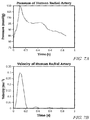
- FIGS. 7A-7F depict waveform analyses derived from evaluation of a human radial artery using a prototype of the vascular impedance measuring device FIG. 1 ;
- FIG. 8 depicts another embodiment of a vascular impedance measuring device using an intravascular wire capable of transducing both pressure and flow, a processing component, and feedback component.
- the present disclosure is directed to vascular impedance measuring devices and methods of using the same. While the apparatuses and methods of the present disclosure may be embodied in many different forms, several specific embodiments are discussed herein with the understanding that the present disclosure is to be considered only as an exemplification of the principles of the disclosure, and it is not intended to limit the disclosure to the embodiments illustrated.
- FIG. 1 A first embodiment of a vascular impedance measuring device 20 is depicted in FIG. 1 .
- a pressure measuring component 22 and a flow measuring component 24 are attached to a target vessel or artery 26 .
- Each of the pressure measuring component 22 and the flow measuring component 24 is operatively connected to a processing component 28 .
- the processing component 28 may be any suitable processor that is capable of receiving data from the pressure measuring component 22 and the flow measuring component 24 and which is programmed to process the data, as will be described in greater detail hereinbelow.
- the processing component 28 may include a display 29 , for example, a computer screen, a mobile device, or any other suitable display that is disposed within a housing or remote from the processing component and which may depict the processed data.
- a feedback component 30 may also be operatively connected to the processor 28 to provide appropriate feedback in the form of therapy to the body. More specifically, the feedback component 30 receives data and/or directions from the processing component 28 and, based on the received data and/or directions, provides an effective means for a physician or operator to provide automated treatment to a patient or targeted artery based on, for example, an impedance calculated by the processing component 28 (or based on any other calculations provided by the processing component 28 ).
- the vascular impedance measuring device 20 through the use of both a pressure measuring component 22 and the flow measuring component 24 , can evaluate a distal impedance of a single artery.
- the present disclosure provides an effective means for a physician or operator to determine impedance of the distal vasculature, where the heart is proximal, of a single point in the arterial system.
- the pressure measuring component 22 may record multiple waves of pressure related to heart cycles or pulse.
- the pressure measuring component 22 may record a discrete number of cycles, discrete duration of cycles, and/or record pressure waves continuously.
- the pressure wave data collected by the pressure measuring component 22 may be automatically transferred to the processing component 28 , for example, in real-time or at any suitable interval of time.
- the pressure wave data may be uploaded in any suitable manner to the processing component 28 .
- the pressure measuring component 22 may be non-invasive using any number of methods, for example, applanation tonometry.
- the pressure measuring component 22 may be implanted adjacent to a targeted vessel, for example, adjacent or around the internal carotid artery 40 with, for example, cuffs 42 , as depicted in FIG. 2 , using any number of methods including applanation tonometry or ultrasound.
- the pressure measuring component 22 may be implanted into the targeted vessel using any number of methods, including catheter-based pressure monitoring, electrical pressure monitoring with a wire probe, and/or any other suitable method. While FIG.
- FIG. 2 depicts the flow measuring component 24 and the pressure measuring component 22 as being adjacent the internal carotid artery 40 , the embodiments of the present disclosure are not limited to such artery. In fact, the principles of the present disclosure or variations thereof may be applied to any suitable vessel or artery.
- the flow measuring component 24 may record multiple waves of flow related to heart cycles or pulse.
- the flow measuring component 24 may record a discrete number of cycles, discrete duration of cycles, and/or record flow waves continuously.
- the flow wave data collected by the flow measuring component 24 may be automatically transferred to the processing component 28 , for example, in real-time or at any suitable interval of time.
- the flow wave data may be uploaded in any suitable manner to the processing component 28 .
- the flow measuring component 24 may be non-invasive using any number of methods, for example, Doppler ultrasound.
- the flow measuring component 24 may be implanted adjacent to a targeted vessel, for example, adjacent or around the internal carotid artery 40 , as depicted in FIG. 2 , using any number of methods including Doppler ultrasound.
- the flow measuring component 24 may be implanted into the targeted vessel using any number of methods, including a direct flow meter, ultrasound, and/or any other suitable method.
- the flow measuring component may be contained within a flow-wire 96 .
- a vascular impedance measuring device 60 includes a pressure measuring component and a flow measuring component combined into one non-invasive probe 62 pressed against the internal carotid artery 40 .
- a pressure signal may be obtained through applanation tonometry 64 through a first portion of the probe 62 and, simultaneously, flow data is obtained through an aligned Doppler ultrasound 66 in a second portion of the probe 62 .
- the probe 62 transmits data to the processing component 28 .
- a similar mechanism of data collection could be performed in other vessels.
- the flow measuring device 24 is depicted as being wrapped around the common carotid artery 70 , but may alternatively be placed around the internal carotid artery or any other suitable artery or vessel.
- a microcatheter 72 may be introduced percutaneously into the occipital artery or other artery and positioned at the origin of the external carotid artery 74 or other artery adjacent to the site of flow measuring device placement. The microcatheter 72 allows pressure transduction and serves as the pressure measuring device.
- a balloon 76 may be mounted on a tip of the microcatheter 72 , which allows isolation of the common and internal carotid arteries for both pressure measurement and delivery of therapeutics from the feedback component 30 . Pressure from the microcatheter 72 and flow data from the flow measuring device 24 may be transmitted to the processing component 28 , shown as two separate parts here. A similar mechanism of data collection and therapy delivery could be performed in other vessels.
- FIG. 5 Another embodiment of the vascular impedance measuring device 20 is depicted in FIG. 5 .
- the device 20 is depicted as being used to assess the renal artery 80 , which supplies blood to the kidney 82 .
- a pressure-measuring wire 84 may be introduced into the renal artery 80 through the aorta 86 .
- Flow data may be obtained from the flow measuring component 24 in the form of a non-invasive Doppler ultrasound, for example. A similar mechanism of data collection could be performed in other vessels.
- FIG. 8 Another embodiment of the vascular impedance measuring device 20 is depicted in FIG. 8 .
- the device uses a wire 92 , which has a pressure-measuring component 94 and a flow-measuring component 96 built into it. [Such a wire is currently commercially available].
- the wire can be inserted through a percutaneously inserted microcatheter 72 .
- the pressure 94 and flow 96 measuring components are connected through the wire 92 to a connector 98 , which transfers the signals to the processing component 22 .
- the processing component may deliver signals to a feedback component 30 , which is capable of therapeutic intervention.
- the processing component 28 may perform any suitable functions, for example, characterization of data received from the flow measuring component 22 , characterization of data from the pressure measuring component 24 , synchronization of flow and pressure data, derivation of reservoir, or steady state, or non-wave-related pressure, derivation of forward and backward waves, display of waves and wave components, display of a vascular impedance value, display of a wave reflection coefficient, signal transmission to the feedback component 30 for delivery of therapy, and/or any other suitable functions. While a number of different functions are disclosed, one skilled in the art will understand that the processing component 28 may implement any one or more of the functions disclosed herein.
- FIG. 6 A flow diagram depicting a data analysis that may be performed using the flow and/or pressure data is depicted in FIG. 6 .
- the data analysis begins at block 100 of FIG. 6 and moves to block 102 , wherein data, such as time, pressure, and velocity are loaded based on constants, such as radius and density, received from block 104 .
- the PU-loop pressure v. speed
- the PU-loop may be displayed and speed of the wave may be calculated at block 106 .
- Peak detection is thereafter performed at block 108 , wherein the highest amplitude point of both flow and pressure waves can be detected and synchronized.
- the processing component 28 may characterize raw data from the flow measuring component 22 by separating the flow component data into waves. This may be accomplished through peak detection or any other suitable method. For elimination of noise within the raw data, the flow component data may be averaged over a length of time or number of cycles to produce an averaged flow wave.
- the processing component 28 may characterize raw data from the pressure measuring component 24 by separating the pressure component data into waves. This may be accomplished through peak detection or any other suitable method. For elimination of noise within the raw data, the pressure component data may be averaged over a length of time or number of cycles to produce an averaged pressure wave.
- the processing component may synchronize the data from the pressure and flow measurement components.
- the synchronization may be accomplished with peak detection or any other suitable method.
- processing is passed to block 110 , wherein an optimal compliance for reservoir pressure is selected.
- the processing component 28 may derive the reservoir pressure of the system (i.e., patient) at block 114 , which represents the blood pressure of the system independent of propagating waves.
- the reservoir pressure of the system may be calculated using the windkessel model on pressure and velocity data collected.
- an exponential decay fit may be applied to the diastolic portion of a collection pressure wave past its maximum value. The decay fit may be further improved using initially determined values and the collected velocity data.
- the arterial compliance may be determined and the reservoir pressure calculated.
- the reservoir pressure may be subtracted from measured pressure data.
- the differential pressure and velocity are then calculated at block 114 based on a calculation of wave speed from block 116 .
- the differential pressure and velocity are then used at block 118 to calculate and display a wave intensity.
- the processing component 28 may thereafter calculate differential forward/backward for pressure and velocity at block 120 and calculate forward/backward pressure and velocity at block 122 .
- the wave separation analysis may be displayed at block 124 .
- the processing component 28 may derive the forward and backward waveforms. After subtracting reservoir pressure from a total pressure, a pressure waveform may be derived. The pressure waveform may be expressed in the time domain or the frequency domain. Given the pressure and flow waveforms, forward and backward waves may be derived using a set of differential equations. This is possible because the forward flow and pressure waves have positive amplitude, but the backward pressure wave has positive amplitude, while the backward flow wave has negative amplitude. The waveforms and waveform components may be displayed by the processing component 28 .
- the value of vascular impedance distal to the site of measurement may be displayed by the processing unit 28 on a display, as noted above.
- the processing component 28 may derive the wave intensity of the forward and backward waves, where wave intensity equals pressure multiplied by flow. Using this wave intensity calculation, the processing unit 28 may display a wave reflection coefficient, equal to backward wave divided by forward wave, that rises as distal impedance rises.
- the processing component 28 may send a signal based on one or more parameters to the feedback component 30 .
- the parameters may be impedance, wave reflection coefficient, and/or any other calculated value.
- the feedback component 30 may allow therapeutic intervention.
- the feedback component 30 may suggest a therapeutic intervention to the physician or operator.
- the feedback component 30 may deliver an intravenous medication.
- the feedback component 30 may deliver intra-arterial medication to the vessel 26 being monitored.
- the feedback component 30 may alert the patient to alter behavior or seek medical attention.
- Other embodiments of feedback may be employed and/or the feedback component 30 may provide any combination of the foregoing methods of feedback.
- an intra-arterial catheter may be placed in or adjacent to the target vessel 26 .
- the intra-arterial catheter may be used as part of the pressure measuring component 22 and the feedback component 30 to deliver intra-arterial medication.
- the device may be used to monitor and/or treat cerebral vasospasm following subarachnoid hemorrhage.
- the pressure and flow measuring components may be implanted to allow continuous monitoring.
- the processing and feedback components may provide continuous, optimized therapy.
- This therapy may include delivery of cardiac and vasoactive medications to optimize blood pressure and heart rate. It may include delivery of intra-arterial spasmolytic agents to treat vasospasm.
- FIGS. 7A-7F show pressure and velocity waveforms following recording and analysis. More particularly, FIGS. 7A and 7B depict a pressure within a human radial artery as a function of time and a velocity of the human radial artery as a function of time, respectively.
- FIG. 7C depicts pressure waveform separation as measured pressure (blue), forward pressure (red), backward pressure (green), and reservoir pressure (black). The forward and backward pressure is shifted up by minimum diastolic pressure to fit into the axes. The wave separation is performed on one cardiac cycle and its corresponding velocity.
- FIG. 7D depicts velocity waveform separation as the measure velocity (blue), forward velocity (red), and backward velocity (green). The wave separation is performed on one cardiac cycle and its corresponding velocity.
- FIG. 7E depicts wave intensity over time and FIG. 7F depicts the PU-loop, which shows pressure as a function of velocity.
- Continuous vasospasm monitoring with the devices presented herein may allow patients to be treated in intensive care units for a shorter duration of time.
- the period of risk for cerebral vasospasm is 2-3 weeks following aneurysmal subarachnoid hemorrhage. Most patients require at least one week of intensive care for vasospasm monitoring even if they do not have other intensive care needs.
- the devices presented may allow early transfer of patients to general monitoring units or rehabilitation units, thus saving enormous health care expenses of intensive care.
- the devices presented herein may serve as research tools to give high-quality feedback for investigational cerebral vasospasm treatment.
- the devices presented herein may play a significant role in future clinical trials for cerebral vasospasm interventions.
- Existing devices can approximate resistance by measuring the pressure at two points in the arterial tree. This provides a resistance approximation for the vessel between those two points. Existing devices cannot determine the resistance or impedance distal to a single point.
- the devices presented herein may provide data for end-organ arterial stenosis, including but not limited to, those within the coronary arteries to the heart and the renal arteries to the kidneys.
- a vessel will have multiple sites of stenosis, and it will be unclear which site is causing symptoms.
- One such condition is tandem stenosis of the cervical internal carotid artery and intracranial carotid artery. In this situation, it is important to treat the diseased vessel, but it may be hazardous to treat both sites of stenosis if only one is preventing adequate flow to the brain.
- the devices presented herein may allow a physician or operator to determine the segmental impedance at each site to guide treatment.
Landscapes
- Health & Medical Sciences (AREA)
- Life Sciences & Earth Sciences (AREA)
- Engineering & Computer Science (AREA)
- Public Health (AREA)
- Heart & Thoracic Surgery (AREA)
- Physics & Mathematics (AREA)
- Biophysics (AREA)
- Pathology (AREA)
- General Health & Medical Sciences (AREA)
- Biomedical Technology (AREA)
- Veterinary Medicine (AREA)
- Medical Informatics (AREA)
- Molecular Biology (AREA)
- Surgery (AREA)
- Animal Behavior & Ethology (AREA)
- Cardiology (AREA)
- Physiology (AREA)
- Vascular Medicine (AREA)
- Hematology (AREA)
- Signal Processing (AREA)
- Computer Vision & Pattern Recognition (AREA)
- Psychiatry (AREA)
- Artificial Intelligence (AREA)
- Biodiversity & Conservation Biology (AREA)
- Nuclear Medicine, Radiotherapy & Molecular Imaging (AREA)
- Radiology & Medical Imaging (AREA)
- Computer Networks & Wireless Communication (AREA)
- Chemical & Material Sciences (AREA)
- Bioinformatics & Cheminformatics (AREA)
- Medicinal Chemistry (AREA)
- Pharmacology & Pharmacy (AREA)
- Measuring Pulse, Heart Rate, Blood Pressure Or Blood Flow (AREA)
Abstract
Description
Claims (17)
Priority Applications (1)
| Application Number | Priority Date | Filing Date | Title |
|---|---|---|---|
| US15/316,018 US10842385B2 (en) | 2014-06-03 | 2015-06-01 | Vascular impedance measuring device and method of determining impedance |
Applications Claiming Priority (3)
| Application Number | Priority Date | Filing Date | Title |
|---|---|---|---|
| US201462007240P | 2014-06-03 | 2014-06-03 | |
| PCT/US2015/033566 WO2015187573A1 (en) | 2014-06-03 | 2015-06-01 | Vascular impedance measuring device and method of determining impedance |
| US15/316,018 US10842385B2 (en) | 2014-06-03 | 2015-06-01 | Vascular impedance measuring device and method of determining impedance |
Publications (2)
| Publication Number | Publication Date |
|---|---|
| US20170086682A1 US20170086682A1 (en) | 2017-03-30 |
| US10842385B2 true US10842385B2 (en) | 2020-11-24 |
Family
ID=54767248
Family Applications (1)
| Application Number | Title | Priority Date | Filing Date |
|---|---|---|---|
| US15/316,018 Expired - Fee Related US10842385B2 (en) | 2014-06-03 | 2015-06-01 | Vascular impedance measuring device and method of determining impedance |
Country Status (2)
| Country | Link |
|---|---|
| US (1) | US10842385B2 (en) |
| WO (1) | WO2015187573A1 (en) |
Families Citing this family (2)
| Publication number | Priority date | Publication date | Assignee | Title |
|---|---|---|---|---|
| WO2019060279A1 (en) * | 2017-09-22 | 2019-03-28 | The Research Institute At Nationwide Children's Hospital | Method and apparatus for malarial-neurologic-injury-mechanism diagnosis |
| GB2570131A (en) * | 2018-01-11 | 2019-07-17 | Imperial Innovations Ltd | Fluid flow analysis |
Citations (3)
| Publication number | Priority date | Publication date | Assignee | Title |
|---|---|---|---|---|
| US5873835A (en) | 1993-04-29 | 1999-02-23 | Scimed Life Systems, Inc. | Intravascular pressure and flow sensor |
| US7794403B2 (en) | 2004-04-21 | 2010-09-14 | Mear Holding B.V. | System for measuring pulsatile vascular resistance |
| US8271080B2 (en) | 2007-05-23 | 2012-09-18 | Cardiac Pacemakers, Inc. | Decongestive therapy titration for heart failure patients using implantable sensor |
-
2015
- 2015-06-01 WO PCT/US2015/033566 patent/WO2015187573A1/en not_active Ceased
- 2015-06-01 US US15/316,018 patent/US10842385B2/en not_active Expired - Fee Related
Patent Citations (3)
| Publication number | Priority date | Publication date | Assignee | Title |
|---|---|---|---|---|
| US5873835A (en) | 1993-04-29 | 1999-02-23 | Scimed Life Systems, Inc. | Intravascular pressure and flow sensor |
| US7794403B2 (en) | 2004-04-21 | 2010-09-14 | Mear Holding B.V. | System for measuring pulsatile vascular resistance |
| US8271080B2 (en) | 2007-05-23 | 2012-09-18 | Cardiac Pacemakers, Inc. | Decongestive therapy titration for heart failure patients using implantable sensor |
Non-Patent Citations (2)
| Title |
|---|
| Search Report and Written Opinion issued in Int'l App. No. PCT/US2015/033566 (dated 2015). |
| Tyberg et al., "Wave intensity analysis and the development of the reservoir-wave approach," Med. Biol. Eng. Comput., 47:221-232 (2009). |
Also Published As
| Publication number | Publication date |
|---|---|
| US20170086682A1 (en) | 2017-03-30 |
| WO2015187573A1 (en) | 2015-12-10 |
Similar Documents
| Publication | Publication Date | Title |
|---|---|---|
| JP7239644B2 (en) | Devices, systems and methods for grading vessels | |
| AU2019218655B2 (en) | Ultrasound blood-flow monitoring | |
| US11793460B2 (en) | Body-worn sensor for characterizing patients with heart failure | |
| JP6783863B2 (en) | Multi-site continuous ultrasonic flow measurement for blood circulation management | |
| JP6684929B2 (en) | RELATED DEVICES, SYSTEMS, AND METHODS FOR DETERMINING PULSE WAVE Velocity Using Intravascular Pressure Measurements and External Ultrasound Imaging | |
| US9339207B2 (en) | Endovascular devices and methods of use | |
| JP6786517B2 (en) | A system for non-invasively monitoring intracranial pressure and how it operates | |
| JP5665776B2 (en) | Estimating hemodynamic data | |
| CN102469947B (en) | Using Signal Transit Time to Monitor Cardiovascular Conditions | |
| US20140187976A1 (en) | Body-worn sensor for characterizing patients with heart failure | |
| WO2020144075A1 (en) | Ultrasound-based closed-loop control of patient therapy | |
| JP7155146B2 (en) | Functional Measurement Patient Interface Module (PIM) for Distributed Wireless Intraluminal Imaging Systems | |
| US20140276137A1 (en) | Systems and methods for determining coronary flow reserve | |
| JP2013542756A (en) | Apparatus and method for guiding a catheter using intravascular energy mapping | |
| WO2012007423A1 (en) | Method and apparatus for the non-invasive measurement of pulse transit times (ptt) | |
| GB2478291A (en) | Endothelium assessment probe | |
| CN102202566A (en) | Blood pressure determination method and device for determining blood pressure | |
| US20250295321A1 (en) | Body-worn sensor for characterizing patients with heart failure | |
| CA3090160A1 (en) | Ultrasound blood-flow monitoring | |
| US20210251504A1 (en) | System and method for determining pulse wave velocity of vessels | |
| US10842385B2 (en) | Vascular impedance measuring device and method of determining impedance | |
| US20220218301A1 (en) | Time-varying quantification of capacitive and resistive arterial blood flow | |
| CA3000814A1 (en) | Blood volume assessment using high frequency ultrasound | |
| CN109350123B (en) | Direct continuous vascular pressure measurement system based on ultrasound transducer | |
| Shah et al. | A proof-of-concept real-time processing to characterize vascular flow |
Legal Events
| Date | Code | Title | Description |
|---|---|---|---|
| AS | Assignment |
Owner name: RUSH UNIVERSITY MEDICAL CENTER, ILLINOIS Free format text: ASSIGNMENT OF ASSIGNORS INTEREST;ASSIGNOR:JOHNSON, ANDREW KELLY;REEL/FRAME:040499/0296 Effective date: 20150723 |
|
| STPP | Information on status: patent application and granting procedure in general |
Free format text: RESPONSE TO NON-FINAL OFFICE ACTION ENTERED AND FORWARDED TO EXAMINER |
|
| STPP | Information on status: patent application and granting procedure in general |
Free format text: NON FINAL ACTION MAILED |
|
| STPP | Information on status: patent application and granting procedure in general |
Free format text: RESPONSE TO NON-FINAL OFFICE ACTION ENTERED AND FORWARDED TO EXAMINER |
|
| STPP | Information on status: patent application and granting procedure in general |
Free format text: NOTICE OF ALLOWANCE MAILED -- APPLICATION RECEIVED IN OFFICE OF PUBLICATIONS |
|
| ZAAA | Notice of allowance and fees due |
Free format text: ORIGINAL CODE: NOA |
|
| ZAAB | Notice of allowance mailed |
Free format text: ORIGINAL CODE: MN/=. |
|
| STPP | Information on status: patent application and granting procedure in general |
Free format text: PUBLICATIONS -- ISSUE FEE PAYMENT VERIFIED |
|
| STCF | Information on status: patent grant |
Free format text: PATENTED CASE |
|
| FEPP | Fee payment procedure |
Free format text: MAINTENANCE FEE REMINDER MAILED (ORIGINAL EVENT CODE: REM.); ENTITY STATUS OF PATENT OWNER: SMALL ENTITY |
|
| LAPS | Lapse for failure to pay maintenance fees |
Free format text: PATENT EXPIRED FOR FAILURE TO PAY MAINTENANCE FEES (ORIGINAL EVENT CODE: EXP.); ENTITY STATUS OF PATENT OWNER: SMALL ENTITY |
|
| STCH | Information on status: patent discontinuation |
Free format text: PATENT EXPIRED DUE TO NONPAYMENT OF MAINTENANCE FEES UNDER 37 CFR 1.362 |
|
| FP | Lapsed due to failure to pay maintenance fee |
Effective date: 20241124 |