US10838610B2 - Graphical user interface control device and method for controlling graphical user interface - Google Patents
Graphical user interface control device and method for controlling graphical user interface Download PDFInfo
- Publication number
- US10838610B2 US10838610B2 US16/476,974 US201716476974A US10838610B2 US 10838610 B2 US10838610 B2 US 10838610B2 US 201716476974 A US201716476974 A US 201716476974A US 10838610 B2 US10838610 B2 US 10838610B2
- Authority
- US
- United States
- Prior art keywords
- area
- target area
- mode
- operation target
- case
- Prior art date
- Legal status (The legal status is an assumption and is not a legal conclusion. Google has not performed a legal analysis and makes no representation as to the accuracy of the status listed.)
- Expired - Fee Related
Links
Images


Classifications
-
- G—PHYSICS
- G06—COMPUTING OR CALCULATING; COUNTING
- G06F—ELECTRIC DIGITAL DATA PROCESSING
- G06F3/00—Input arrangements for transferring data to be processed into a form capable of being handled by the computer; Output arrangements for transferring data from processing unit to output unit, e.g. interface arrangements
- G06F3/01—Input arrangements or combined input and output arrangements for interaction between user and computer
- G06F3/048—Interaction techniques based on graphical user interfaces [GUI]
- G06F3/0484—Interaction techniques based on graphical user interfaces [GUI] for the control of specific functions or operations, e.g. selecting or manipulating an object, an image or a displayed text element, setting a parameter value or selecting a range
- G06F3/0485—Scrolling or panning
-
- G—PHYSICS
- G06—COMPUTING OR CALCULATING; COUNTING
- G06F—ELECTRIC DIGITAL DATA PROCESSING
- G06F3/00—Input arrangements for transferring data to be processed into a form capable of being handled by the computer; Output arrangements for transferring data from processing unit to output unit, e.g. interface arrangements
- G06F3/01—Input arrangements or combined input and output arrangements for interaction between user and computer
- G06F3/03—Arrangements for converting the position or the displacement of a member into a coded form
- G06F3/041—Digitisers, e.g. for touch screens or touch pads, characterised by the transducing means
- G06F3/0412—Digitisers structurally integrated in a display
-
- G—PHYSICS
- G06—COMPUTING OR CALCULATING; COUNTING
- G06F—ELECTRIC DIGITAL DATA PROCESSING
- G06F3/00—Input arrangements for transferring data to be processed into a form capable of being handled by the computer; Output arrangements for transferring data from processing unit to output unit, e.g. interface arrangements
- G06F3/01—Input arrangements or combined input and output arrangements for interaction between user and computer
- G06F3/048—Interaction techniques based on graphical user interfaces [GUI]
- G06F3/0487—Interaction techniques based on graphical user interfaces [GUI] using specific features provided by the input device, e.g. functions controlled by the rotation of a mouse with dual sensing arrangements, or of the nature of the input device, e.g. tap gestures based on pressure sensed by a digitiser
- G06F3/0488—Interaction techniques based on graphical user interfaces [GUI] using specific features provided by the input device, e.g. functions controlled by the rotation of a mouse with dual sensing arrangements, or of the nature of the input device, e.g. tap gestures based on pressure sensed by a digitiser using a touch-screen or digitiser, e.g. input of commands through traced gestures
Definitions
- the present invention relates to a graphical user interface (hereinafter referred to as GUI) control device for controlling a GUI related to an operation target area displayed on a screen and a method for controlling the GUI.
- GUI graphical user interface
- Electronic devices that accept operation on an operation target area displayed on a screen of a display device are widely used.
- a touch panel is arranged on the screen, and operation on the operation target area displayed on the screen is accepted as touch operation by the touch panel.
- Touch operation includes, for example, flick operation, tap operation, and slide operation.
- Flick operation is to flick or to sweep the screen in a scroll direction with a finger or the like.
- Tap operation is to touch the screen shortly with a finger.
- Slide operation is to move the finger touching the screen in a certain direction.
- Patent Literature 1 JP 2015-46009 A
- the portion for receiving the flick operation in the first operation target area is narrow. Therefore, operability for scrolling the first operation target area is not good enough, and erroneous operation is likely to occur.
- the present invention solves the problems as the above, and an object of the present invention is to provide a GUI control device and a method for controlling a GUI that are capable of suppressing erroneous operation.
- a GUI control device includes a display processing unit, an operation determination unit, and a control unit.
- the display processing unit displays, on a screen, an operation target area in which processing corresponding to first operation and processing corresponding to second operation which is different from the first operation can be executed.
- the operation determination unit determines operation executed on the operation target area.
- the control unit sets one of a first operation mode, in which the first operation is enabled and the second operation is disabled, and a second operation mode, in which the first operation is disabled and the second operation is enabled, to the operation target area and executes processing corresponding to the first operation or the second operation depending on the set operation mode.
- the control unit switches the operation mode of the operation target area.
- either the first operation mode or the second operation mode is set to an operation target area, and processing corresponding to the first operation or the second operation is executed depending on the set operation mode.
- the third operation is executed on the operation target area, the operation mode of the operation target area is switched.
- the third operation allows the first operation and the second operation to be switched between enabled and disabled states, erroneous operation can be suppressed in which the first operation is erroneously recognized as the second operation, or the second operation erroneously recognized as the first operation.
- FIG. 1 is a block diagram illustrating a functional configuration of a GUI control device according to a first embodiment of the present invention.
- FIG. 2A is a block diagram illustrating a hardware configuration of an electronic device according to the first embodiment.
- FIG. 2B is a block diagram illustrating a hardware configuration for executing software that implements functions of the electronic device according to the first embodiment.
- FIG. 3 is a flowchart illustrating an overview of the operation of the GUI control device according to the first embodiment.
- FIG. 4A is a diagram illustrating a first example of a GUI screen according to the first embodiment.
- FIG. 4B is a diagram illustrating a second example of a GUI screen according to the first embodiment.
- FIG. 4C is a diagram illustrating a third example of a GUI screen according to the first embodiment.
- FIG. 4D is a diagram illustrating a fourth example of a GUI screen according to the first embodiment.
- FIG. 5 is a flowchart illustrating details of the operation of the GUI control device according to the first embodiment.
- FIG. 6 is a block diagram illustrating a functional configuration of a GUI control device according to a second embodiment of the present invention.
- FIG. 7 is a flowchart illustrating an overview of the operation of the GUI control device according to the second embodiment.
- FIG. 8A is a diagram illustrating a first example of a GUI screen according to the second embodiment.
- FIG. 8B is a diagram illustrating a second example of a GUI screen according to the second embodiment.
- FIG. 8C is a diagram illustrating a third example of a GUI screen according to the second embodiment.
- FIG. 8D is a diagram illustrating a fourth example of a GUI screen according to the second embodiment.
- FIG. 9A is a diagram illustrating a fifth example of a GUI screen according to the second embodiment.
- FIG. 9B is a diagram illustrating a sixth example of a GUI screen according to the second embodiment.
- FIG. 9C is a diagram illustrating a seventh example of a GUI screen according to the second embodiment.
- FIG. 9D is a diagram illustrating an eighth example of a GUI screen according to the second embodiment.
- FIG. 10 is a flowchart illustrating discrimination processing of touch operation according to the second embodiment.
- FIG. 11 is a flowchart illustrating processing when an event of tap operation occurs.
- FIG. 12 is a flowchart illustrating processing when an event of flick operation or slide operation occurs.
- FIG. 13 is a block diagram illustrating a functional configuration of a GUI control device according to a third embodiment of the present invention.
- FIG. 14 is a flowchart illustrating an overview of the operation of the GUI control device according to the third embodiment.
- FIG. 15A is a diagram illustrating a first example of a GUI screen according to the third embodiment.
- FIG. 15B is a diagram illustrating a second example of a GUI screen according to the third embodiment.
- FIG. 15C is a diagram illustrating a third example of a GUI screen according to the third embodiment.
- FIG. 15D is a diagram illustrating a fourth example of a GUI screen according to the third embodiment.
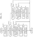
- FIG. 16 is a flowchart illustrating processing corresponding to operation on an operation target area in the third embodiment.
- FIG. 17 is a flowchart illustrating processing corresponding to operation on a mode-switching area in the third embodiment.
- FIG. 1 is a block diagram illustrating a functional configuration of a GUI control device 1 according to a first embodiment of the present invention.
- the GUI control device 1 is provided in an in-vehicle electronic device, for example, and controls the GUI between an operator and the in-vehicle electronic device.
- the GUI control device 1 includes a display processing unit 10 , an operation determination unit 11 , a control unit 12 , an area information storing unit 13 , and a graphic data storing unit 14 .
- the display processing unit 10 displays an image based on graphic data received from the control unit 12 on a screen of a display device. For example, the display processing unit 10 displays, on the screen, an operation target area in which processing corresponding to first operation and processing corresponding to second operation can be executed.
- a touch panel is provided on the screen of the display device and that this touch panel accepts touch operation on an operation target area.
- the first operation is flick operation or slide operation to which processing of scrolling an operation target area is assigned. It is assumed that the second operation is operation different from the first operation and is tap operation to which processing of selecting an object in an operation target area is assigned.
- the operation determination unit 11 determines operation executed on an operation target area. For example, the operation determination unit 11 determines the operation executed on the operation target area on the basis of event information of the touch operation on the operation target area. The operation determination unit 11 determines the type of touch operation, the operation position, or an object to be operated. The types of touch operation include flick operation, tap operation, and slide operation.
- the control unit 12 sets one of the first operation mode and the second operation mode on the operation target area and executes processing corresponding to the first operation or the second operation depending on the operation mode.
- the first operation In the first operation mode, the first operation is enabled, whereas the second operation is disabled, and in the second operation mode the first operation is disabled, whereas the second operation is enabled.
- Disabled means that even when operation is executed, processing corresponding to this operation is not executed, and “enabled” means that when operation is executed, processing corresponding to this operation is executed.
- control unit 12 executes processing of scrolling the operation target area since the first operation is “enabled.”
- control unit 12 when the second operation is executed on the operation target area, the control unit 12 does not execute processing corresponding to selection of an object since the second operation is “disabled.”
- control unit 12 When the first operation is executed on an operation target area in which the second operation mode is set, the control unit 12 does not execute processing of scrolling the operation target area since the first operation is “disabled.”
- control unit 12 executes processing corresponding to selection of an object since the second operation is “enabled.”
- control unit 12 switches the operation mode of the operation target area.
- the operation mode is switched to the second operation mode.
- the operation mode is switched to the first operation mode.
- the third operation is different from the first operation and the second operation.
- the third operation is, for example, slide operation in which an angle formed by the operation direction with respect to a direction in which the operation target area can be scrolled is equal to or more than a threshold value.
- the area information storing unit 13 stores area information related to operation target areas.
- Information related to an operation target area includes operation mode set to the operation target area.
- the graphic data storing unit 14 stores graphic data of operation target areas. Graphic data of an operation target area also includes graphic data of an operation target area to be transitioned to upon selection of an object in the operation target area.
- the control unit 12 receives discrimination information of touch operation from the operation determination unit 11 , reads an operation mode of the operation target area from the area information storing unit 13 , and executes processing corresponding to operation executed on the operation target area depending on this operation mode.
- control unit 12 switches and updates the operation mode in the area information of the operation target area stored in the area information storing unit 13 .
- the control unit 12 requests graphic data corresponding to the operation to the graphic data storing unit 14 , reads the graphic data corresponding to the request, and sends the data to the display processing unit 10 .
- the display processing unit 10 displays an operation target area on the screen on the basis of the graphic data received from the control unit 12 .
- GUI control device 1 including the area information storing unit 13 and the graphic data storing unit 14 is illustrated; however, no limitation thereto is intended.
- the storage devices may be provided separately from the GUI control device 1 . That is, the area information storing unit 13 and the graphic data storing unit 14 are not indispensable components to the GUI control device 1 .
- FIG. 2A is a block diagram illustrating a hardware configuration of the electronic device according to the first embodiment and illustrates an electronic device including the GUI control device 1 .
- FIG. 2B is a block diagram illustrating a hardware configuration for executing software implementing the functions of the electronic device according to the first embodiment and, likewise, illustrating an electronic device including the GUI control device 1 .
- the electronic device includes an input control unit 100 , an input device 101 , an output control unit 102 , and a display device 103 .
- the input control unit 100 generates event information of operation from detection information of the operation detected by the input device 101 .
- the event information of touch operation is a signal indicating the contents of the touch operation including the area touched and the type of the touch operation.
- the input device 101 accepts operation by an operator and is implemented by a touch panel.
- the operation determination unit 11 receives event information from the input control unit 100 and determines the operation executed on the operation target area via the input device 101 which is a touch panel from the operation contents indicated by the event information.
- the output control unit 102 displays display information on the screen of the display device 103 .
- the display device 103 is a display monitor included in the electronic device.
- the display processing unit 10 generates display information of the operation target area on the basis of the graphic data received from the control unit 12 and outputs the display information to the output control unit 102 .
- the output control unit 102 displays the operation target area on the screen of the display device 103 on the basis of the display information input from the display processing unit 10 .
- the functions of the display processing unit 10 , the operation determination unit 11 , the control unit 12 , the area information storing unit 13 , and the graphic data storing unit 14 in the GUI control device 1 are implemented by a processing circuit. That is, the GUI control device 1 includes a processing circuit for executing these functions.
- the processing circuit may be dedicated hardware or a central processing unit (CPU) for executing a program stored in a memory.
- the processing circuit is a processing circuit 104 of dedicated hardware as illustrated in FIG. 2A
- the processing circuit 104 may be a single circuit, a composite circuit, a programmed processor, a parallel programmed processor, an application specific integrated circuit (ASIC), a field-programmable gate array (FPGA), or a combination thereof.
- ASIC application specific integrated circuit
- FPGA field-programmable gate array
- the functions of the display processing unit 10 , the operation determination unit 11 , the control unit 12 , the area information storing unit 13 , and the graphic data storing unit 14 in the GUI control device 1 may be implemented by separate processing circuits, or the respective functions may be implemented collectively by a single processing circuit.
- the processing circuit is a CPU 105 illustrated in FIG. 2B
- the functions of the display processing unit 10 , the operation determination unit 11 , the control unit 12 , the area information storing unit 13 , and the graphic data storing unit 14 are implemented by software, firmware, or a combination of software and firmware.
- Software and firmware are described as a program and stored in a memory 106 .
- the memory 106 may include a random access memory (RAM) and a read only memory (ROM).
- the RAM stores data generated by information processing such as screen data displayed on the display device 103 and control data necessary for execution of the program
- the ROM stores the program to be executed by the CPU 105 .
- the CPU 105 reads and executes the program stored in the memory 106 and thereby implements the respective functions.
- the GUI control device 1 includes the memory for storing the program, upon executed by the processing circuit, which results in execution of processing from step ST 1 to step ST 4 illustrated in FIG. 3 .
- programs cause a computer to execute the procedures or methods of the display processing unit 10 , the operation determination unit 11 , the control unit 12 , the area information storing unit 13 , and the graphic data storing unit 14 .
- the memory may include a nonvolatile or volatile semiconductor memory such as a RAM, a ROM, a flash memory, an erasable programmable ROM (EPROM), or an electrically EPROM (EEPROM); a magnetic disc, a flexible disc, an optical disc, a compact disc, a mini disc, or a digital versatile disk (DVD).
- a nonvolatile or volatile semiconductor memory such as a RAM, a ROM, a flash memory, an erasable programmable ROM (EPROM), or an electrically EPROM (EEPROM); a magnetic disc, a flexible disc, an optical disc, a compact disc, a mini disc, or a digital versatile disk (DVD).
- Some of the functions of the display processing unit 10 , the operation determination unit 11 , the control unit 12 , the area information storing unit 13 , and the graphic data storing unit 14 may be implemented by dedicated hardware and a rest thereof may be implemented by software or firmware.
- the area information storing unit 13 and the graphic data storing unit 14 implement functions thereof by a processing circuit of dedicated hardware, and functions of the display processing unit 10 , the operation determination unit 11 , and the control unit 12 are implemented by the CPU 105 executing the program stored in the memory 106 .
- the processing circuit can implement the functions described above by hardware, software, firmware, or a combination thereof.
- FIG. 3 is a flowchart illustrating the outline of the operation of the GUI control device 1 , and illustrates a series of processing from the time when an operation target area is displayed on the screen to the time when processing corresponding to operation is executed.
- the display processing unit 10 displays an operation target area on the screen of the display device 103 on the basis of graphic data received from the control unit 12 (step ST 1 ).
- the operation determination unit 11 determines operation executed on the operation target area displayed on the screen (step ST 2 ).
- step ST 2 If the operation executed on the operation target area is either the first operation or the second operation (step ST 2 : first operation or second operation), the control unit 12 executes processing corresponding to the first operation or the second operation depending on an operation mode (step ST 3 ).
- control unit 12 executes processing of scrolling the operation target area.
- the control unit 12 does not execute processing corresponding to selection of an object even when the second operation is executed on the operation target area.
- control unit 12 does not execute processing of scrolling the operation target area even when the first operation is executed on the operation target area.
- control unit 12 executes processing corresponding to selection of an object.
- step ST 2 If the operation executed in the operation target area is the third operation (step ST 2 : third operation), the control unit 12 switches the operation mode of the operation target area (step ST 4 ).
- control unit 12 switches and updates the operation mode in the area information of the operation target area stored in the area information storing unit 13 .
- the operation mode is switched to the second operation mode.
- the operation mode is switched to the first operation mode.
- step ST 3 the processing is executed.
- GUI screens in the first embodiment will be described with specific examples.
- FIGS. 4A to 4D are diagrams illustrating specific examples of a GUI screen according to the first embodiment.
- FIG. 4A is a diagram illustrating a GUI screen 31 .
- FIG. 4B is a diagram illustrating a GUI screen 32 .
- FIG. 4C is a diagram illustrating a GUI screen 33 .
- FIG. 4D is a diagram illustrating a GUI screen 34 .
- An area 311 illustrated in FIG. 4A , an area 321 illustrated in FIG. 4B , an area 331 illustrated in FIG. 4C , and an area 341 illustrated in FIG. 4D are operation target areas which can be scrolled only in the vertical direction.
- a first operation mode in which operation corresponding to scroll processing is enabled and operation corresponding to selection of an object is disabled is set.
- a second operation mode in which operation corresponding to scroll processing is disabled and operation corresponding to selection of an object is enabled is set.
- a bar 3111 illustrated in FIG. 4A , a bar 3211 illustrated in FIG. 4B , a bar 3311 illustrated in FIG. 4C , and a bar 3411 illustrated in FIG. 4D indicate that the area 311 , the area 321 , the area 331 , and the area 341 can be scrolled in the vertical direction.
- the lengths of the bars 3111 , 3211 , 3311 , and 3411 correspond to the amount of information that can be viewed in the areas 311 , 321 , 331 , and 341 , respectively.
- a bar 3112 illustrated in FIG. 4A , a bar 3212 illustrated in FIG. 4B , a bar 3312 illustrated in FIG. 4C , and a bar 3412 illustrated in FIG. 4D indicate the positions in the vertical direction of the information currently displayed on the screen, out of information that can be viewed in the area 311 , the area 321 , the area 331 , and the area 341 , respectively.
- the information currently displayed on the screen is information at the scrollable upper limit position of the area 311 .
- the lengths of the bars 3112 , 3212 , 3312 , and 3412 correspond to the amount of information currently displayed on the screen.
- a text 3113 illustrated in FIG. 4A , a text 3313 illustrated in FIG. 4C , and a text 3413 illustrated in FIG. 4D are text items each set with a hyperlink. These text items are objects that can be selected by tap operation.
- Marks 3314 and 3315 illustrated in FIG. 4C are images indicating that the second operation mode, in which scroll processing is disabled, is set in the area 331 . An operator can recognize from the marks 3314 and 3315 that the area 331 cannot be scrolled.
- an operation target area is displayed on the screen in a display mode specified for each operation mode.
- a direction oriented upward in the drawings along a linear line forming an angle of less than 45 degrees with respect to a scrollable direction in the areas 311 , 321 , 331 , and 341 , respectively, is defined as an upward direction
- a direction oriented downward in the drawings along the linear line is defined as a downward direction.
- a direction oriented leftward in the drawings along a linear line forming an angle of equal to or greater than 45 degrees with respect to the scrollable direction in the areas 311 , 321 , 331 , and 341 is defined as a leftward direction
- a direction oriented rightward in the drawings along the linear line is defined as a rightward direction.
- the operator can perform flick operation or slide operation in the vertical direction and the horizontal direction in each of the areas 311 , 321 , 331 , and 341 .
- the control unit 12 does not execute processing corresponding to the selection of the text 3113 . As a result, the display on the GUI screen 31 remains unchanged.
- the control unit 12 executes scrolling of the area 311 .
- the display device 103 displays the GUI screen 32 which is the result of scrolling the area 311 .
- the control unit 12 switches the operation mode of the area 311 to the second operation mode.
- the display device 103 displays the GUI screen 33 in which the marks 3314 and 3315 are drawn.
- the control unit 12 executes scrolling of the area 321 .
- the display device 103 displays the GUI screen 31 which is the result of scrolling the area 321 .
- control unit 12 switches the operation mode of the area 321 to the second operation mode.
- the display device 103 displays a GUI screen on which marks indicating that scrolling cannot be executed are drawn. This GUI screen is not illustrated.
- the control unit 12 executes processing corresponding to the selection of the text 3313 .
- the display device 103 displays the GUI screen 34 corresponding to the selection of the text 3313 under the control by the display processing unit 10 .
- control unit 12 switches the operation mode of the area 331 to the first operation mode.
- the display device 103 Under the control by the display processing unit 10 instructed by the control unit 12 , the display device 103 hides the marks 3314 and 3315 and displays the GUI screen 31 .
- control unit 12 executes scrolling of the area 341 .
- the display device 103 displays a GUI screen which is the result of scrolling the area 341 . This GUI screen is not illustrated.
- the control unit 12 switches the operation mode of the area 341 to the second operation mode.
- the display device 103 displays a GUI screen in which the marks 3314 and 3315 are displayed. This GUI screen is not illustrated.
- FIG. 5 is a flowchart illustrating details of the operation of the GUI control device 1 , and illustrates details of processing from the time when an operation target area is displayed on the screen to the time when processing corresponding to operation is executed.
- the operation determination unit 11 determines whether the detected touch operation is tap operation (step ST 402 ).
- the control unit 12 confirms whether the second operation mode is set to the operation target area (step ST 403 ).
- the second operation mode is an operation mode in which scroll operation is disabled and the object selection operation is enabled.
- step ST 403 If the second operation mode is set to the operation target area (step ST 403 ; YES), the control unit 12 executes processing corresponding to selection of an object by tap operation (step ST 404 ). According to an instruction from the control unit 12 , the display processing unit 10 displays a screen based on the execution result of the processing on the display device 103 (step ST 405 ). If the second operation mode is not set to the operation target area (step ST 403 ; NO), the control unit 12 terminates the processing without any further action.
- the operation determination unit 11 determines whether the touch operation is flick operation or slide operation in which the angle formed by the operation direction with respect to the scrollable direction in the operation target area is less than 45 degrees (step ST 406 ).
- the control unit 12 confirms whether the first operation mode is set to the operation target area (step ST 407 ).
- the first operation mode is an operation mode in which scroll operation is enabled and object selection operation is disabled.
- step ST 407 If the first operation mode is set to the operation target area (step ST 407 ; YES), the control unit 12 executes processing of scrolling the operation target area (step ST 408 ).
- the display processing unit 10 displays a screen obtained by scrolling the operation target area on the display device 103 (step ST 409 ). Then, the processing is terminated. If the first operation mode is not set to the operation target area (step ST 407 ; NO), the processing is terminated.
- step ST 406 determines whether it is slide operation in which the angle is equal to or greater than 45 degrees. If it is determined as not being slide operation in which the angle is equal to or greater than 45 degrees (step ST 410 ; NO), the processing is terminated.
- step ST 410 If it is determined as slide operation in which the angle is equal to or greater than 45 degrees (step ST 410 ; YES), the control unit 12 determines that the third operation has been executed and switches the operation mode of the operation target area (step ST 411 ).
- the display processing unit 10 displays a screen corresponding to the operation mode after switching on the display device 103 (step ST 412 ). Then, the processing is terminated.
- control unit 12 may execute processing corresponding to selection of an object and may further switch the operation target area to the first operation mode.
- control unit 12 executes processing corresponding to selection of an object and then to switch the operation target area to the first operation mode, a newly displayed operation target area becomes scrollable, thereby facilitating viewing of the information.
- the control unit 12 sets one of the first operation mode and the second operation mode to the operation target area, and executes processing corresponding to the first operation or the second operation depending on the set operation mode.
- the control unit 12 switches the operation mode of the operation target area.
- the first operation is touch operation for scrolling the operation target area, and in particular, flick operation or slide operation in which the angle formed by an operation direction with respect to a scrollable direction in the operation target area is less than a threshold value.
- the second operation is touch operation for selecting an object in the operation target area.
- the third operation is different from the first operation and the second operation.
- the third operation is, for example, slide operation in which the angle formed by the operation direction with respect to a direction in which the operation target area can be scrolled is equal to or more than the threshold value.
- the third operation allows the first operation and the second operation to be switched between enabled and disabled states, erroneous operation can be suppressed in which the first operation is erroneously recognized as the second operation, or the second operation erroneously recognized as the first operation.
- FIG. 6 is a block diagram illustrating a functional configuration of a GUI control device 1 A according to a second embodiment of the present invention.
- the GUI control device 1 A is provided in an in-vehicle electronic device, for example, and controls the GUI between an operator and the in-vehicle electronic device.
- the GUI control device 1 A includes a display processing unit 10 A, an operation determination unit 11 A, a control unit 12 A, an area information storing unit 13 A, and a graphic data storing unit 14 A.
- the display processing unit 10 A displays the image based on graphic data received from the control unit 12 A on the screen of the display device 103 illustrated in FIGS. 2A and 2B .
- the display processing unit 10 A displays each of a plurality of operation target areas, on which processing corresponding to the first operation and processing corresponding to the second operation can be executed, on the screen in alignment.
- the display processing unit 10 A displays each of the plurality of operation target areas such that an inner area is arranged within an outer area on the screen.
- a touch panel is provided on the screen of the display device 103 and that this touch panel accepts touch operation on an operation target area.
- the first operation is flick operation or slide operation to which processing of scrolling an operation target area is assigned. It is assumed that the second operation is operation different from the first operation and is tap operation to which processing of selecting an object in an operation target area is assigned.
- the operation determination unit 11 A determines operation executed on each of the plurality of operation target areas.
- the operation determination unit 11 A determines operation executed on the operation target areas on the basis of an input control signal corresponding to touch operation on each of the plurality of operation target areas.
- the control unit 12 A sets one of the first operation mode and the second operation mode to each of the plurality of operation target areas and executes processing corresponding to the first operation or the second operation depending on the operation mode.
- the control unit 12 A executes processing of scrolling the operation target area since the first operation is “enabled.” Even when the second operation is executed on this operation target area, since the second operation is “disabled,” the control unit 12 A does not execute processing corresponding to the selection of an object.
- the control unit 12 A when the first operation is executed on an operation target area in which the second operation mode is set, the control unit 12 A does not execute processing of scrolling the operation target area since the first operation is “disabled.” However, when the second operation is executed on this operation target area, the control unit 12 A executes processing corresponding to the selection of an object since the second operation is “enabled.”
- control unit 12 A switches the operation mode of an operation target area in which operation determined by the operation determination unit 11 A is the third operation from among the plurality of operation target areas.
- the operation mode is switched to the second operation mode.
- the operation mode is switched to the first operation mode.
- the third operation is different from the first operation and the second operation.
- the third operation is, for example, slide operation in which an angle formed by the operation direction with respect to a direction in which the operation target area can be scrolled is equal to or more than a threshold value.
- the area information storing unit 13 A stores area information related to operation target areas.
- Information related to operation target areas includes operation modes set to each of the plurality of operation target areas.
- the graphic data storing unit 14 A stores graphic data of the plurality of operation target areas. Each piece of the graphic data of the plurality of operation target areas also includes graphic data of an operation target area to be transitioned to upon selection of an object in an operation target area. The graphic data also includes information indicating a positional relationship and an inclusion relation among the operation target areas.
- the control unit 12 A receives discrimination information of touch operation from the operation determination unit 11 A, reads an operation mode of an operation target area from the area information storing unit 13 A, and executes processing corresponding to operation executed on the operation target area depending on the operation mode.
- control unit 12 A switches and updates the operation mode in the area information of the operation target area stored in the area information storing unit 13 A.
- the control unit 12 A requests graphic data corresponding to the executed operation to the graphic data storing unit 14 A, reads the graphic data corresponding to the request, and sends the data to the display processing unit 10 A.
- the display processing unit 10 A displays an operation target area on the screen on the basis of the graphic data received from the control unit 12 A.
- GUI control device 1 A including the area information storing unit 13 A and the graphic data storing unit 14 A is illustrated; however, no limitation thereto is intended.
- the storage devices may be provided separately from the GUI control device 1 A. That is, the area information storing unit 13 A and the graphic data storing unit 14 A are not indispensable components to the GUI control device 1 A.
- the functions of the display processing unit 10 A, the operation determination unit 11 A, the control unit 12 A, the area information storing unit 13 A, and the graphic data storing unit 14 A in the GUI control device 1 A are implemented by a processing circuit. That is, the GUI control device 1 A includes a processing circuit for executing these functions.
- the processing circuit may be dedicated hardware or a CPU that executes a program stored in a memory.
- the processing circuit 104 corresponds to, for example, a single circuit, a composite circuit, a programmed processor, a parallel programmed processor, an ASIC, an FPGA, or a combination thereof.
- the functions of the display processing unit 10 A, the operation determination unit 11 A, the control unit 12 A, the area information storing unit 13 A, and the graphic data storing unit 14 A in the GUI control device 1 A may be implemented by separate processing circuits, or the respective functions may be implemented collectively by a single processing circuit.
- the functions of the display processing unit 10 A, the operation determination unit 11 A, the control unit 12 A, the area information storing unit 13 A, and the graphic data storing unit 14 A are implemented by software, firmware, or a combination of software and firmware.
- Software and firmware are described as a program and stored in a memory 106 .
- the memory 106 may include a RAM and a ROM.
- the RAM stores screen data displayed on the display device 103 and data generated by information processing such as control data necessary for execution of the program
- the ROM stores the program to be executed by the CPU 105 .
- the CPU 105 reads and executes the program stored in the memory 106 and thereby implements the respective functions.
- the GUI control device 1 A includes the memory for storing the program, upon executed by the processing circuit, which results in execution of processing from step ST 1 a to step ST 4 a illustrated in FIG. 7 .
- programs cause a computer to execute the procedures or methods of the display processing unit 10 A, the operation determination unit 11 A, the control unit 12 A, the area information storing unit 13 A, and the graphic data storing unit 14 A.
- Some of the functions of the display processing unit 10 A, the operation determination unit 11 A, the control unit 12 A, the area information storing unit 13 A, and the graphic data storing unit 14 A may be implemented by dedicated hardware and a rest thereof may be implemented by software or firmware.
- the area information storing unit 13 A and the graphic data storing unit 14 A implement functions thereof by a processing circuit of dedicated hardware, and functions of the display processing unit 10 A, the operation determination unit 11 A, and the control unit 12 A are implemented by the CPU 105 executing the program stored in the memory 106 .
- the processing circuit can implement the functions described above by hardware, software, firmware, or a combination thereof.
- FIG. 7 is a flowchart illustrating the outline of the operation of the GUI control device 1 A, and illustrates a series of processing from the time when an operation target area is displayed on the screen to the time when processing corresponding to operation is executed.
- the display processing unit 10 A displays a plurality of operation target areas on the screen of the display device 103 on the basis of graphic data received from the control unit 12 A (step ST 1 a ).
- the operation determination unit 11 A determines operation executed on each of the plurality of operation target areas displayed on the screen (step ST 2 a ).
- step ST 2 a first operation or second operation
- the control unit 12 A executes processing corresponding to the first operation or the second operation depending on an operation mode of the operation target area on which this operation is executed among the plurality of operation target areas (step ST 3 a ).
- control unit 12 A executes processing of scrolling the operation target area.
- the control unit 12 A does not execute processing corresponding to selection of an object even when the second operation is executed on the operation target area.
- control unit 12 A does not execute processing of scrolling the operation target area even when the first operation is executed on the operation target area.
- the control unit 12 A executes processing corresponding to selection of an object when the second operation is executed on the operation target area.
- step ST 2 a third operation
- the control unit 12 A switches the operation mode of the operation target area in which the third operation is executed (step ST 4 a ).
- control unit 12 A switches and updates the operation mode in area information of the operation target area in which the third operation is executed out of the area information stored in the area information storing unit 13 A.
- the operation mode is switched to the second operation mode, and if the second operation mode is set, the operation mode is switched to the first operation mode.
- step ST 3 a the flow proceeds to processing in step ST 3 a , and the processing is executed.
- GUI screens in the second embodiment will be described with specific examples.
- FIGS. 8A to 8D and FIGS. 9A to 9D illustrate specific examples of GUI screens in the second embodiment.
- FIG. 8A is a diagram illustrating a GUI screen 51 .
- FIG. 8B is a diagram illustrating a GUI screen 52 .
- FIG. 8C is a diagram illustrating a GUI screen 53 .
- FIG. 8D is a diagram illustrating a GUI screen 54 .
- FIG. 9A is a diagram illustrating a GUI screen 55 .
- FIG. 9B is a diagram illustrating a GUI screen 56 .
- FIG. 9C is a diagram illustrating a GUI screen 57 .
- FIG. 9D is a diagram illustrating a GUI screen 58 .
- An area 511 illustrated in FIG. 8A , an area 521 illustrated in FIG. 8B , an area 531 illustrated in FIG. 8C , an area 541 illustrated in FIG. 8D , an area 551 illustrated in FIG. 9A , an area 561 illustrated in FIG. 9B , and an area 581 illustrated in FIG. 9D are operation target areas that can be scrolled only in the vertical direction.
- An area 512 illustrated in FIG. 8A , an area 522 illustrated in FIG. 8B , an area 542 illustrated in FIG. 8D , an area 552 illustrated in FIG. 9A , an area 562 illustrated in FIG. 9B , and an area 582 illustrated in FIG. 9D are operation target areas that can be scrolled only in the vertical direction.
- the area 512 is arranged inside the area 511 . That is, the area 511 is an outer area, and the area 512 is an inner area.
- the area 522 (inner area) is arranged inside the area 521 (outer area).
- the area 542 (inner area) is arranged inside the area 541 (outer area).
- the area 552 (inner area) is arranged inside the area 551 (outer area).
- the area 562 (inner area) is arranged inside the area 561 (outer area).
- the area 582 (inner area) is arranged inside the area 581 (outer area).
- the first operation mode in which operation corresponding to scroll processing is enabled and operation corresponding to selection of an object is disabled is set.
- the second operation mode in which operation corresponding to scroll processing is disabled and operation corresponding to selection of an object is enabled is set.
- Bars 5111 and 5121 illustrated in FIG. 8A , bars 5211 and 5221 illustrated in FIG. 8B , a bar 5311 illustrated in FIG. 8C , bars 5411 and 5421 illustrated in FIG. 8D , bars 5511 and 5521 illustrated in FIG. 9A , bars 5611 and 5621 illustrated in FIG. 9B , and bars 5811 and 5821 illustrated in FIG. 9D indicate that the areas 511 and 512 , the areas 521 and 522 , the area 531 , the areas 541 and 542 , the areas 551 and 552 , the areas 561 and 562 , and the areas 581 and 582 , respectively, can be scrolled only in the vertical direction.
- the length of each of these bars corresponds to the amount of information viewable in each of the areas including the bar.
- Bars 5112 and 5122 illustrated in FIG. 8A , bars 5212 and 5222 illustrated in FIG. 8B , a bar 5312 illustrated in FIG. 8C , bars 5412 and 5422 illustrated in FIG. 8D , bars 5512 and 5522 illustrated in FIG. 9A , bars 5612 and 5622 illustrated in FIG. 9B , and bars 5812 and 5822 illustrated in FIG. 9D indicate the position in the vertical direction in the information currently displayed on the screen in the information that can be viewed in the areas 511 and 512 , the areas 521 and 522 , the area 531 , the areas 541 and 542 , the areas 551 and 552 , the areas 561 and 562 , and the areas 581 and 582 , respectively.
- the lengths of these bars correspond to the amount of information currently displayed on the screen.
- Texts 5113 and 5123 illustrated in FIG. 8A , texts 5213 and 5223 illustrated in FIG. 8B , texts 5413 and 5423 illustrated in FIG. 8D , texts 5513 and 5523 illustrated in FIG. 9A , a text 5623 illustrated in FIG. 9B , and texts 5813 and 5823 illustrated in FIG. 9D are text items each set with a hyperlink. These text items are objects that can be selected by tap operation.
- Marks 5424 and 5425 illustrated in FIG. 8D , marks 5514 and 5515 illustrated in FIG. 9A , a mark 5625 illustrated in FIG. 9B , marks 5814 and 5815 and marks 5824 and 5825 illustrated in FIG. 9D are images indicating that the second operation mode in which scroll processing is disabled is set to the areas 542 , 551 , 562 , 581 , and 582 . An operator can recognize from these marks that the above areas cannot be scrolled.
- an operation target area is displayed on the screen in a display mode specified for each operation mode.
- a direction oriented upward in the drawings along a linear line forming an angle of less than 45 degrees with respect to a scrollable direction in the areas 511 , 512 , 521 , 522 , 531 , 541 , 542 , 551 , 552 , 561 , 562 , 581 , and 582 is defined as an upward direction
- a direction oriented downward in the drawings along the linear line is defined as a downward direction.
- a direction oriented leftward in the drawings along a linear line forming an angle of equal to or greater than 45 degrees with respect to the scrollable direction in these areas is defined as a leftward direction
- a direction oriented rightward in the drawings along the linear line is defined as a rightward direction.
- operation determined by the operation determination unit 11 A in the GUI screen 51 is tap operation (second operation) of the text 5113 in the area 511 or the text 5123 in the area 512 is taken as an example.
- the control unit 12 A since the first operation mode is set in both the area 511 and the area 512 , the control unit 12 A does not execute processing corresponding to selection of the text 5113 or the text 5123 . As a result, the display on the GUI screen 51 remains unchanged.
- the control unit 12 A executes scrolling of the area 512 .
- the display device 103 displays the GUI screen 52 which is the result of scrolling the area 512 .
- the control unit 12 A executes scrolling of the area 511 .
- the display device 103 displays a GUI screen 53 which is the result of scrolling the area 511 .
- the control unit 12 A switches the operation mode of the area 512 to the second operation mode.
- the display device 103 displays the marks 5424 and 5425 indicating that scrolling cannot be executed under the control by the display processing unit 10 A instructed by the control unit 12 A. As a result, the GUI screen 54 is displayed on the screen.
- the control unit 12 A switches the operation mode of the area 511 to the second operation mode.
- the display device 103 displays the marks 5514 and 5515 indicating that scrolling cannot be executed under the control by the display processing unit 10 A instructed by the control unit 12 A. As a result, the GUI screen 55 is displayed on the screen.
- the control unit 12 A does not execute processing corresponding to selection of the text 5213 or the text 5223 . As a result, the display on the GUI screen 52 remains unchanged.
- operation determined by the operation determination unit 11 A is downward flick operation or slide operation (first operation) in the area 522
- first operation mode is set in the area 522
- the control unit 12 A executes scrolling of the area 522 .
- the display device 103 Under the control by the display processing unit 10 A, the display device 103 displays the GUI screen 51 which is the result of scrolling the area 522 .
- operation determined by the operation determination unit 11 A is upward flick operation or slide operation (first operation) in the area 521
- the control unit 12 A executes scrolling of the area 521 .
- the display device 103 Under the control by the display processing unit 10 A, the display device 103 displays a GUI screen which is the result of scrolling the area 521 . This GUI screen is not illustrated.
- the control unit 12 A switches the operation mode of the area 522 to the second operation mode.
- the display device 103 displays the marks 5424 and 5425 indicating that scrolling cannot be executed under the control by the display processing unit 10 A instructed by the control unit 12 A. This GUI screen is not illustrated.
- the control unit 12 A switches the operation mode of the area 521 to the second operation mode.
- the display device 103 displays the marks 5514 and 5515 indicating that scrolling cannot be executed under the control by the display processing unit 10 A instructed by the control unit 12 A. This GUI screen is not illustrated.
- the display device 103 Under the control by the display processing unit 10 A, the display device 103 displays the GUI screen 51 which is the result of scrolling the area 531 .
- the control unit 12 A switches the operation mode of the area 531 to the second operation mode.
- the display device 103 displays the marks 5514 and 5515 indicating that scrolling cannot be executed under the control by the display processing unit 10 A instructed by the control unit 12 A. This GUI screen is not illustrated.
- the control unit 12 A since the first operation mode is set in the area 541 though the second operation mode is set in the area 542 , the control unit 12 A does not execute processing corresponding to selection of the text 5423 . As a result, the display on the GUI screen 54 remains unchanged.
- the control unit 12 A does not execute processing corresponding to the selection of the text 5413 . As a result, the display on the GUI screen 54 remains unchanged.
- the control unit 12 A executes scrolling of the area 541 .
- the display device 103 displays the GUI screen 56 which is the result of scrolling the area 541 .
- the control unit 12 A executes scrolling of the area 541 .
- the display device 103 displays the GUI screen 56 which is the result of scrolling the area 541 .
- the control unit 12 A switches the operation mode of the area 542 to the first operation mode.
- the display device 103 hides the marks 5424 and 5425 , and the GUI screen 51 is displayed on the screen.
- the control unit 12 A switches the operation mode of the area 541 to the second operation mode.
- the display device 103 displays the marks 5814 and 5815 under the control by the display processing unit 10 A instructed by the control unit 12 A, and the GUI screen 58 is displayed on the screen.
- the control unit 12 A does not execute processing corresponding to the selection of the text 5523 . As a result, the display on the GUI screen 55 remains unchanged.
- operation determined by the operation determination unit 11 A is tap operation (second operation) of the text 5513 in the area 551
- the control unit 12 A executes processing corresponding to the selection of the text 5513 .
- the display device 103 displays the GUI screen 57 corresponding to the selection of the text 5513 under the control by the display processing unit 10 A.
- the control unit 12 A executes scrolling of the area 552 .
- the display device 103 displays a GUI screen which is the result of scrolling the area 552 . This GUI screen is not illustrated.
- operation determined by the operation determination unit 11 A is upward flick operation or slide operation (first operation) in the area 551
- the control unit 12 A since the second operation mode is set in the area 551 , the control unit 12 A does not execute scrolling of the area 551 .
- the display on the GUI screen 55 remains unchanged.
- the control unit 12 A switches the operation mode of the area 552 to the second operation mode.
- the display device 103 displays marks 5824 and 5825 indicating that scrolling cannot be executed under the control by the display processing unit 10 A instructed by the control unit 12 A. As a result, the GUI screen 58 is displayed on the screen.
- the control unit 12 A switches the operation mode of the area 551 to the first operation mode.
- the display device 103 hides the marks 5514 and 5515 indicating that scrolling cannot be executed under the control by the display processing unit 10 A instructed by the control unit 12 A. As a result, the GUI screen 51 is displayed on the screen.
- the control unit 12 A does not execute processing corresponding to the selection of the text 5623 . As a result, the display on the GUI screen 56 remains unchanged.
- operation determined by the operation determination unit 11 A is downward flick operation or slide operation (first operation) in the area 562
- first operation mode is set in the area 561 though the second operation mode is set in the area 562
- the control unit 12 A executes scrolling of the area 561 .
- the display device 103 displays the GUI screen 54 which is the result of scrolling the area 561 .
- control unit 12 A executes scrolling of the area 561 .
- the display device 103 displays the GUI screen 54 which is the result of scrolling the area 561 .
- the control unit 12 A switches the operation mode of the area 562 to the first operation mode.
- the display device 103 hides the mark 5625 indicating that scrolling cannot be executed under the control by the display processing unit 10 A instructed by the control unit 12 A. This GUI screen is not illustrated.
- the control unit 12 A switches the operation mode of the area 561 to the second operation mode.
- the display device 103 displays the marks 5814 and 5815 indicating that scrolling cannot be executed under the control by the display processing unit 10 A instructed by the control unit 12 A. This GUI screen is not illustrated.
- the control unit 12 A executes processing corresponding to the selection of the text 5823 .
- the display device 103 displays the GUI screen 53 corresponding to the selection of the text 5823 under the control by the display processing unit 10 A.
- operation determined by the operation determination unit 11 A is tap operation (second operation) of the text 5813 in the area 581
- the control unit 12 A executes processing corresponding to the selection of the text 5813 .
- the display device 103 displays the GUI screen 57 corresponding to the selection of the text 5813 under the control by the display processing unit 10 A.
- operation determined by the operation determination unit 11 A is upward flick operation or slide operation (first operation) in the area 581 or the area 582
- the control unit 12 A since the second operation mode is set in the area 581 and the area 582 , the control unit 12 A does not execute scrolling of the area 581 or the area 582 .
- the display on the GUI screen 58 remains unchanged.
- the control unit 12 A switches the operation mode of the area 582 to the first operation mode.
- the display device 103 hides the marks 5824 and 5825 indicating that scrolling cannot be executed under the control by the display processing unit 10 A instructed by the control unit 12 A. As a result, the GUI screen 55 is displayed.
- the control unit 12 A switches the operation mode of the area 581 to the first operation mode.
- the display device 103 hides the marks 5814 and 5815 indicating that scrolling cannot be executed under the control by the display processing unit 10 A instructed by the control unit 12 A. As a result, the GUI screen 54 is displayed.
- FIG. 10 is a flowchart illustrating processing for discriminating touch operation according to the second embodiment, which illustrates a series of processing from detection of touch operation by the touch panel to occurrence of an event of touch operation.
- FIG. 11 is a flowchart illustrating processing when an event of tap operation occurs, which is executed for each operation target area.
- FIG. 12 is a flowchart illustrating processing when an event of flick operation or slide operation occurs, which is executed for each operation target area.
- the input control unit 100 Upon detecting touch operation on an operation target area, the input control unit 100 outputs event information of the touch operation to the operation determination unit 11 A.
- the operation determination unit 11 A recognizes that touch operation has been detected by receiving the event information of the touch operation.
- the operation determination unit 11 A determines whether the detected touch operation is tap operation (step ST 602 ). In this example, the text 5823 is tapped (step ST 602 ; YES).
- the operation determination unit 11 A searches for the outermost area from the touched position in the plurality of operation target areas (areas 581 and 582 ) on the GUI screen 58 (step ST 603 ).
- the area 582 is touched, the area 581 is searched as the operation target area on the outermost position from the touched position.
- the operation determination unit 11 A sends, to the control unit 12 A, that event information of the touch operation is that of an event of touch operation of the searched area 581 (step ST 604 ).
- control unit 12 A Upon receiving the event of the touch operation in the area 581 , the control unit 12 A confirms whether the operation mode of the area 581 is the second operation mode (step ST 701 ).
- the operation determination unit 11 A confirms whether the area 581 is the innermost operation target area in the operation target areas including the touched position (step ST 702 ).
- the operation determination unit 11 A searches for the outermost operation target area out of operation target areas included in the operation target area (area 581 ) including the touched position (step ST 705 ).
- the area 582 is searched as the operation target area that matches the above search conditions out of the operation target areas included in the area 581 .
- the operation determination unit 11 A sends, to the control unit 12 A, that the touch operation on the area 582 is an event of touch operation of the searched area 582 (step ST 706 ).
- control unit 12 A Upon receiving the event of the touch operation of the area 582 from the operation determination unit 11 A, the control unit 12 A proceeds to step ST 701 .
- the operation determination unit 11 A confirms whether the area 582 is the innermost operation target area in the operation target areas including the touched position (step ST 702 ).
- step ST 703 Since the area 582 is the innermost operation target area in the operation target areas including the touched position (step ST 702 ; YES), the control unit 12 A executes processing corresponding to selection of the text 5823 (step ST 703 ).
- the display device 103 Under the control by the display processing unit 10 A, the display device 103 displays a GUI screen corresponding to selection of the text 5823 (step ST 704 ). In this manner, a series of processing completes.
- the operation determination unit 11 A determines whether the detected touch operation is tap operation (step ST 602 ). In this example, the text 5113 is tapped (step ST 602 ; YES).
- the operation determination unit 11 A searches for the outermost operation target area from the touched position in the plurality of operation target areas (areas 511 and 512 ) (step ST 603 ).
- the area 511 is searched as the outermost operation target area from the touched position.
- the operation determination unit 11 A sends, to the control unit 12 A, that event information of the touch operation is that of an event of touch operation of the searched area 511 (step ST 604 ).
- control unit 12 A Upon receiving the event of the touch operation in the area 511 , the control unit 12 A confirms whether the operation mode of the area 511 is the second operation mode (step ST 701 ).
- step ST 701 Since the first operation mode is set in the area 511 (step ST 701 ; NO), the control unit 12 A terminates the processing without any further action.
- the operation determination unit 11 A determines whether the detected touch operation is tap operation (step ST 602 ). Here, it is determined that the detected touch operation is not tap operation (step ST 602 ; NO).
- the operation determination unit 11 A determines whether the detected touch operation is flick operation or slide operation (step ST 605 ). It is determined that upward flick operation is executed in the area 512 (step ST 605 ; YES).
- step ST 606 the operation determination unit 11 A searches for the innermost operation target area including the touched position.
- the area 512 is searched as the innermost operation target area including the touched position.
- the operation determination unit 11 A determines that event information of the touch operation is that of an event of touch operation of the searched area 512 (step ST 604 ).
- the operation determination unit 11 A determines whether the touch operation determined as the event in the area 512 is flick operation or slide operation in which the angle formed by the operation direction with respect to a scrollable direction in the area 512 is less than 45 degrees (step ST 801 ).
- step ST 801 Since the touch operation is upward flick operation in the area 512 , it is determined as flick operation that satisfies the above conditions (step ST 801 ; YES).
- the control unit 12 A confirms whether the operation mode of the area 512 where the flick operation has been executed is the first operation mode (step ST 802 ).
- step ST 802 Since the first operation mode is set in the area 512 (step ST 802 ; YES), the control unit 12 A executes scroll processing of the area 512 (step ST 803 ).
- the display device 103 displays a GUI screen obtained by scrolling the area 512 (step ST 804 ). In this manner, a series of processing completes.
- the operation determination unit 11 A determines whether the detected touch operation is tap operation (step ST 602 ). Here, it is determined that the detected touch operation is not tap operation (step ST 602 ; NO).
- the operation determination unit 11 A determines whether the detected touch operation is flick operation or slide operation (step ST 605 ). It is determined that upward flick operation is executed in the area 542 (step ST 605 ; YES).
- the operation determination unit 11 A searches for the innermost operation target area including the touched position (step ST 606 ).
- the area 542 is searched as the innermost operation target area including the touched position.
- the operation determination unit 11 A determines that event information of the touch operation is that of an event of touch operation of the searched area 542 (step ST 604 ).
- the operation determination unit 11 A determines whether the touch operation determined as the event in the area 542 is flick operation or slide operation in which the angle formed by the operation direction with respect to a scrollable direction in the area 542 is less than 45 degrees (step ST 801 ).
- step ST 801 Since the touch operation is upward flick operation in the area 542 , it is determined as flick operation that satisfies the above conditions (step ST 801 ; YES).
- the control unit 12 A confirms whether the operation mode of the area 542 where the flick operation has been executed is the first operation mode (step ST 802 ).
- the operation determination unit 11 A determines whether the area 542 is the outermost operation target area including the touched position (step ST 805 ).
- the operation determination unit 11 A searches for the innermost operation target area including the operation target area including the touched position (step ST 806 ).
- the operation target area including the touched position is the area 542 in which it is determined that the event of touch operation has occurred in step ST 604 .
- the area 541 is searched as the operation target area that matches the above search conditions.
- the operation determination unit 11 A determines that event information of the touch operation is that of an event of touch operation of the searched area 541 (step ST 807 ).
- the operation determination unit 11 A determines whether the touch operation determined as the event in the area 541 is flick operation or slide operation in which the angle formed by the operation direction with respect to a scrollable direction in the area 541 is less than 45 degrees (step ST 801 ).
- step ST 801 Since the touch operation is upward flick operation in the area 541 , it is determined as flick operation that satisfies the above conditions (step ST 801 ; YES).
- the control unit 12 A confirms whether the operation mode of the area 541 where the flick operation has been executed is the first operation mode (step ST 802 ).
- step ST 802 Since the first operation mode is set in the area 541 (step ST 802 ; YES), the control unit 12 A executes scroll processing of the area 541 (step ST 803 ).
- the display device 103 displays a GUI screen obtained by scrolling the area 541 (step ST 804 ). In this manner, a series of processing completes.
- the operation determination unit 11 A determines whether the detected touch operation is tap operation (step ST 602 ). Here, it is determined that the detected touch operation is not tap operation (step ST 602 ; NO).
- the operation determination unit 11 A determines whether the detected touch operation is flick operation or slide operation (step ST 605 ). It is determined that upward flick operation is executed in the area 551 (step ST 605 ; YES).
- the operation determination unit 11 A searches for the innermost operation target area including the touched position (step ST 606 ).
- the area 551 is searched as the innermost operation target area including the touched position.
- the operation determination unit 11 A determines that event information of the touch operation is that of an event of touch operation of the searched area 551 (step ST 604 ).
- the operation determination unit 11 A determines whether the touch operation determined as the event in the area 551 is flick operation or slide operation in which the angle formed by the operation direction with respect to a scrollable direction in the area 551 is less than 45 degrees (step ST 801 ).
- step ST 801 Since the touch operation is upward flick operation in the area 551 , it is determined as flick operation that satisfies the above conditions (step ST 801 ; YES).
- the control unit 12 A confirms whether the operation mode of the area 551 where the flick operation has been executed is the first operation mode (step ST 802 ).
- the operation determination unit 11 A determines whether the area 551 is the outermost operation target area including the touched position (step ST 805 ).
- step ST 805 Since the area 551 is the outermost operation target area including the touched position (step ST 805 ; YES), the control unit 12 A terminates the processing without any further action.
- the operation determination unit 11 A determines whether the detected touch operation is tap operation (step ST 602 ). Here, it is determined that the detected touch operation is not tap operation (step ST 602 ; NO).
- the operation determination unit 11 A determines whether the detected touch operation is flick operation or slide operation (step ST 605 ). It is determined that rightward slide operation is executed in the area 512 (step ST 605 ; YES).
- the operation determination unit 11 A searches for the innermost operation target area including the touched position (step ST 606 ).
- the area 512 is searched as the innermost operation target area including the touched position.
- the operation determination unit 11 A determines that event information of the touch operation is that of an event of touch operation of the searched area 512 (step ST 604 ).
- the operation determination unit 11 A determines whether the touch operation determined as the event in the area 512 is flick operation or slide operation in which the angle formed by the operation direction with respect to a scrollable direction in the area 512 is less than 45 degrees (step ST 801 ).
- step ST 801 Since the touch operation is rightward slide operation in the area 512 , it is determined as the slide operation that does not satisfy the above conditions (step ST 801 ; NO).
- the operation determination unit 11 A determines whether the touch operation determined as an event in the area 512 is slide operation in which the angle formed by the operation direction with respect to a scrollable direction in the area 512 is equal to or greater than 45 degrees (step ST 808 ).
- step ST 808 Since the touch operation is rightward slide operation in the area 512 , it is determined as the slide operation that satisfies the above conditions (step ST 808 ; YES).
- control unit 12 A switches the operation mode of the area 512 (step ST 809 ).
- the control unit 12 A switches the operation mode of the area 512 to the second operation mode.
- the display device 103 displays a GUI screen indicating that scrolling cannot be executed under the control by the display processing unit 10 A instructed by the control unit 12 A (step ST 810 ).
- the operation determination unit 11 A determines whether the detected touch operation is tap operation (step ST 602 ). Here, it is determined that the detected touch operation is not tap operation (step ST 602 ; NO).
- the operation determination unit 11 A determines whether the detected touch operation is flick operation or slide operation (step ST 605 ). It is determined that rightward flick operation is executed in the area 511 (step ST 605 ; YES).
- the operation determination unit 11 A searches for the innermost operation target area including the touched position (step ST 606 ). Here, since there is no inner operation target area including the touched position, the area 511 is searched.
- the operation determination unit 11 A determines that event information of the touch operation is that of an event of touch operation of the searched area 511 (step ST 604 ).
- the operation determination unit 11 A determines whether the touch operation determined as the event in the area 511 is flick operation or slide operation in which the angle formed by the operation direction with respect to a scrollable direction in the area 511 is less than 45 degrees (step ST 801 ).
- step ST 801 Since the touch operation is rightward flick operation in the area 511 , it is determined as flick operation that does not satisfy the above conditions (step ST 801 ; NO).
- the operation determination unit 11 A determines whether the touch operation determined as an event in the area 511 is slide operation in which the angle formed by the operation direction with respect to a scrollable direction in the area 511 is equal to or greater than 45 degrees (step ST 808 ). Since the touch operation is rightward flick operation in the area 511 , it is determined as slide operation that does not satisfy the above conditions (step ST 808 ; NO), and the processing is terminated.
- the operation determination unit 11 A determines whether the detected touch operation is tap operation (step ST 602 ). Here, it is determined that the detected touch operation is not tap operation (step ST 602 ; NO).
- the operation determination unit 11 A determines whether the detected touch operation is flick operation or slide operation (step ST 605 ). Since pinch operation has been executed in the area 511 (step ST 605 ; NO), the processing is terminated.
- a first operation target area and a second operation target area may be displayed on the screen in alignment.
- the control unit 12 A In the case where, in the first operation target area in which the second operation mode is set, operation determined by the operation determination unit 11 A is the first operation, the control unit 12 A does not execute scrolling of the first operation target area in the case where the second operation mode is set in the second operation target area. At this time, in the case where the first operation mode is set in the second operation target area, the control unit 12 A scrolls the second operation target area.
- the second operation target area is scrolled.
- erroneous operation that the first operation is erroneously recognized as the second operation or that the second operation is erroneously recognized as the first operation can be suppressed.
- the display processing unit 10 A displays a plurality of operation target areas on the screen.
- the operation determination unit 11 A determines operation executed on each of the plurality of operation target areas.
- the control unit 12 A sets one of the first operation mode and the second operation mode to each of the plurality of operation target areas and executes processing corresponding to the first operation or the second operation depending on the set operation mode.
- the control unit 12 A switches, out of the plurality of operation target areas, the operation mode of an operation target area in which the operation determined by the operation determination unit 11 A is the third operation.
- the first operation is touch operation for scrolling the operation target area, and in particular, flick operation or slide operation in which the angle formed by an operation direction with respect to a scrollable direction in the operation target area is less than a threshold value.
- the second operation is touch operation for selecting an object in the operation target area.
- the third operation is different from the first operation and the second operation.
- the third operation is, for example, slide operation in which an angle formed by the operation direction with respect to a direction in which the operation target area can be scrolled is equal to or more than a threshold value.
- the third operation allows the first operation and the second operation to be switched between enabled and disabled states, erroneous operation can be suppressed in which the first operation is erroneously recognized as the second operation, or the second operation is erroneously recognized as the first operation.
- the display processing unit 10 A displays each of the plurality of operation target areas such that an inner area is arranged within an outer area on the screen.
- the control unit 12 A does not execute processing corresponding to selection of an object when the first operation mode is set in the outer area including the inner area. In this example, if the second operation mode is set in the outer area, the control unit 12 A executes processing corresponding to the selection of an object. In the case where operation determined by the operation determination unit 11 A is the first operation, the control unit 12 A does not execute processing of scrolling the inner area when the second operation mode is set in the outer area including the inner area. In this example, if the first operation mode is set in the outer area, the control unit 12 A executes processing of scrolling the outer area. This can enhance operability for performing the first operation on the outer area.
- first operation flick operation
- flick operation is erroneously executed on the portion occupied by the area 512 when scrolling the area 511 is intended, in the conventional art, the area 512 is scrolled.
- execution of the third operation on the area 512 to switch to the second operation mode avoids the area 512 from being scrolled even when flick operation is executed on the portion occupied by the area 512 .
- the area 511 can be scrolled.
- the above effect becomes remarkable as the area of an inner area within an outer area is larger since it becomes more difficult to flick the portion of the outer area that is not occupied by the inner area.
- FIG. 13 is a block diagram illustrating a functional configuration of a GUI control device 1 B according to a third embodiment of the present invention.
- the GUI control device 1 B is provided in an in-vehicle electronic device, for example, and controls the GUI between an operator and the in-vehicle electronic device.
- the GUI control device 1 B includes a display processing unit 10 B, an operation determination unit 11 B, a control unit 12 B, an area information storing unit 13 B, and a graphic data storing unit 14 B.
- the display processing unit 10 B displays the image based on graphic data received from the control unit 12 B on the screen of the display device 103 illustrated in FIGS. 2A and 2B .
- the display processing unit 10 B displays an operation target area in which processing corresponding to the first operation and processing corresponding to the second operation can be executed and a mode-switching area corresponding thereto adjacent to each other on the screen.
- a mode-switching area is an area operated for switching the operation mode of the operation target area, and operation on this mode-switching area corresponds to the third operation.
- Arranging these areas adjacent to each other facilitates execution of switching the operation mode.
- the operation determination unit 11 B determines operation executed on the operation target area and the mode-switching area. For example, the operation determination unit 11 B determines operation executed on these operation target areas on the basis of input control signals corresponding to touch operation on each of the operation target area and the mode-switching area.
- the control unit 12 B sets one of the first operation mode and the second operation mode in the operation target area and executes processing corresponding to the first operation or the second operation depending on the operation mode.
- control unit 12 B switches the operation mode of the operation target area corresponding to the mode-switching area.
- the area information storing unit 13 B stores area information related to operation target areas.
- Information related to an operation target area includes operation mode of the operation target area.
- the graphic data storing unit 14 B stores graphic data of operation target areas and graphic data of mode-switching areas.
- Graphic data of an operation target area also includes graphic data of an operation target area to be transitioned to upon selection of an object in the operation target area.
- Graphic data of a mode-switching area may be in different display modes before and after execution of operation in the mode-switching area. This allows an operator to recognize an operation mode from the display mode of the mode-switching area.
- the control unit 12 B receives discrimination information of touch operation from the operation determination unit 11 B, reads an operation mode of an operation target area from the area information storing unit 13 B, and executes processing corresponding to operation executed on the operation target area depending on the operation mode.
- control unit 12 B When operation is executed on the mode-switching area, the control unit 12 B switches and updates the operation mode in area information of the operation target area corresponding to this mode-switching area.
- the control unit 12 B requests graphic data corresponding to the executed operation to the graphic data storing unit 14 B, reads the graphic data corresponding to the request, and sends the data to the display processing unit 10 B.
- the display processing unit 10 B displays the operation target area and the mode-switching area on the screen on the basis of the graphic data received from the control unit 12 B.
- GUI control device 1 B including the area information storing unit 13 B and the graphic data storing unit 14 B is illustrated; however, no limitation thereto is intended.
- the storage devices may be provided separately from the GUI control device 1 B.
- the area information storing unit 13 B and the graphic data storing unit 14 B are not indispensable components to the GUI control device 1 B.
- the functions of the display processing unit 10 B, the operation determination unit 11 B, the control unit 12 B, the area information storing unit 13 B, and the graphic data storing unit 14 B in the GUI control device 1 B are implemented by a processing circuit. That is, the GUI control device 1 B includes processing circuit for executing these functions.
- the processing circuit may be dedicated hardware or a CPU that executes a program stored in a memory.
- the processing circuit 104 corresponds to, for example, a single circuit, a composite circuit, a programmed processor, a parallel programmed processor, an ASIC, an FPGA, or a combination thereof.
- the functions of the display processing unit 10 B, the operation determination unit 11 B, the control unit 12 B, the area information storing unit 13 B, and the graphic data storing unit 14 B in the GUI control device 1 B may be implemented by separate processing circuits, or the respective functions may be implemented collectively by a single processing circuit.
- the functions of the display processing unit 10 B, the operation determination unit 11 B, the control unit 12 B, the area information storing unit 13 B, and the graphic data storing unit 14 B are implemented by software, firmware, or a combination of software and firmware.
- Software and firmware are described as a program and stored in a memory 106 .
- the memory 106 may include a RAM and a ROM.
- the RAM stores data generated by information processing such as screen data displayed on the display device 103 and control data necessary for execution of the program
- the ROM stores the program to be executed by the CPU 105 .
- the CPU 105 reads and executes the program stored in the memory 106 and thereby implements the respective functions. That is, the GUI control device 1 B includes the memory for storing the program, upon executed by the processing circuit, which results in execution of processing from step ST 1 b to step ST 4 b illustrated in FIG. 14 .
- Such programs cause a computer to execute the procedures or methods of the display processing unit 10 B, the operation determination unit 11 B, the control unit 12 B, the area information storing unit 13 B, and the graphic data storing unit 14 B.
- Some of the functions of the display processing unit 10 B, the operation determination unit 11 B, the control unit 12 B, the area information storing unit 13 B, and the graphic data storing unit 14 B may be implemented by dedicated hardware and a rest thereof may be implemented by software or firmware.
- the area information storing unit 13 B and the graphic data storing unit 14 B implement functions thereof by a processing circuit of dedicated hardware, and functions of the display processing unit 10 B, the operation determination unit 11 B, and the control unit 12 B are implemented by the CPU 105 executing the program stored in the memory 106 .
- the processing circuit can implement the functions described above by hardware, software, firmware, or a combination thereof.
- FIG. 14 is a flowchart illustrating the outline of the operation of the GUI control device 1 B, and illustrates a series of processing from the time when an operation target area is displayed on the screen to the time when processing corresponding to operation is executed.
- the display processing unit 10 B displays an operation target area and a mode-switching area on the screen of the display device 103 on the basis of graphic data received from the control unit 12 B (step ST 1 b ).
- the operation determination unit 11 B determines operation executed on the operation target area and the mode-switching area displayed on the screen (step ST 2 b ).
- step ST 2 b first operation or second operation
- the control unit 12 B executes processing corresponding to the first operation or the second operation depending on the operation mode of the operation target area on which the operation is executed (step ST 3 b ).
- control unit 12 B executes processing of scrolling the operation target area.
- the control unit 12 B does not execute processing corresponding to selection of an object even when the second operation is executed on the operation target area.
- control unit 12 B does not execute processing of scrolling the operation target area even when the first operation is executed on the operation target area.
- the control unit 12 B executes processing corresponding to selection of an object when the second operation is executed on the operation target area.
- step ST 2 b operation on mode-switching area
- the control unit 12 B switches the operation mode of the operation target area corresponding to the mode-switching area (step ST 4 b ).
- control unit 12 B switches and updates the operation mode in area information of the operation target area corresponding to the mode-switching area out of the area information stored in the area information storing unit 13 B.
- the operation mode is switched to the second operation mode, and if the second operation mode is set, the operation mode is switched to the first operation mode. Thereafter, the flow proceeds to processing in step ST 3 b , and the processing is executed.
- GUI screens in the third embodiment will be described with specific examples.
- FIGS. 15A to 15D are diagrams illustrating specific examples of a GUI screen according to the third embodiment.
- FIG. 15A is a diagram illustrating a GUI screen 91 .
- FIG. 15B is a diagram illustrating the GUI screen 92 .
- FIG. 15C is a diagram illustrating the GUI screen 93 .
- FIG. 15D is a diagram illustrating the GUI screen 94 .
- An area 911 illustrated in FIG. 15A , an area 921 illustrated in FIG. 15B , and an area 931 illustrated in FIG. 15C are operation target areas which can be scrolled in any direction.
- the first operation mode in which operation corresponding to scroll processing is enabled and operation corresponding to selection of an object is disabled is set.
- the second operation mode in which operation corresponding to scroll processing is disabled and operation corresponding to selection of an object is enabled is set.
- An area 912 illustrated in FIG. 15A , an area 922 illustrated in FIG. 15B , and an area 932 illustrated in FIG. 15C are mode-switching areas corresponding to the areas 911 , 921 , and 931 , respectively.
- marks on the left side in which an arrow is drawn to indicate whether scroll operation is enabled, are selected, which indicates that the areas 911 and 921 corresponding thereto are in the first operation mode.
- a mark on the right side in which a circle is drawn to indicate whether selecting operation on an object is enabled, which indicates that the area 931 corresponding to the area 932 is in the second operation mode.
- An object 9111 illustrated in FIG. 15A , an object 9211 illustrated in FIG. 15B , and an object 9311 illustrated in FIG. 15C are images selectable by tap operation.
- An operator can execute flick operation or slide operation on the areas 911 , 921 , and 931 .
- the operator can perform tap operation, rightward flick operation or slide operation on the area 912 and the area 922 .
- the operator can execute tap operation, leftward flick operation or slide operation on the area 932 .
- the control unit 12 B does not execute processing corresponding to selection of the object 9111 . In this case, the display on the GUI screen 91 remains unchanged.
- the control unit 12 B executes scrolling of the area 911 .
- the display device 103 displays the GUI screen 92 which is the result of scrolling the area 911 .
- the control unit 12 B switches the area 911 to the second operation mode.
- the display device 103 changes the display of the area 912 to that of the area 932 under control by the display processing unit 10 B instructed by the control unit 12 B. As a result, the GUI screen 93 is displayed.
- the control unit 12 B does not execute processing corresponding to selection of the object 9211 . As a result, the display on the GUI screen 92 remains unchanged.
- the control unit 12 B executes scrolling of the area 921 .
- the display device 103 displays the GUI screen 91 which is the result of scrolling the area 921 .
- the control unit 12 B switches the area 921 to the second operation mode.
- the display device 103 changes the display of the area 922 to that of the area 932 under control by the display processing unit 10 B instructed by the control unit 12 B. A resulting GUI screen is not illustrated.
- the control unit 12 B executes processing corresponding to selection of the object 9311 .
- the display device 103 displays the GUI screen 94 corresponding to the selection of the object 9311 under control by the display processing unit 10 B.
- the control unit 12 B switches the area 931 to the first operation mode.
- the display device 103 displays the GUI screen 91 obtained by changing the display of the area 932 to that of the area 912 under control by the display processing unit 10 B instructed by the control unit 12 B.
- FIG. 16 is a flowchart illustrating processing corresponding to operation on an operation target area.
- a first operation target area illustrated in FIG. 16 is an operation target area in which processing corresponding to the first operation and processing corresponding to the second operation can be executed.
- the input control unit 100 Upon detection of touch operation on an operation target area, the input control unit 100 outputs event information of the touch operation to the operation determination unit 11 B.
- the operation determination unit 11 B recognizes that touch operation has been detected by receiving the event information of the touch operation.
- the operation determination unit 11 B determines whether the detected touch operation is tap operation (step ST 1002 ).
- step ST 1002 If the touch operation executed on the first operation target area is tap operation (step ST 1002 ; YES), the control unit 12 B confirms whether the second operation mode is set in the first operation target area (step ST 1003 ).
- step ST 1003 If the second operation mode is set in the first operation target area (step ST 1003 ; YES), the control unit 12 B executes processing corresponding to selection of an object by the tap operation (step ST 1004 ). Under control by the display processing unit 10 B, the display device 103 displays a GUI screen corresponding to the selection of an object (step ST 1005 ).
- step ST 1003 If the second operation mode is not set in the first operation target area (step ST 1003 ; NO), the processing is terminated.
- the operation determination unit 11 B determines whether the detected touch operation is flick operation or slide operation (step ST 1006 ).
- step ST 1006 If the detected touch operation is flick operation or slide operation (step ST 1006 ; YES), the control unit 12 B confirms whether the first operation mode is set in the first operation target area (step ST 1007 ).
- step ST 1007 If the first operation mode is set in the first operation target area (step ST 1007 ; YES), the control unit 12 B scrolls the first operation target area depending on the flick operation or the slide operation (step ST 1008 ).
- the display device 103 Under control by the display processing unit 10 B, the display device 103 displays a screen obtained by scrolling the first operation target area (step ST 1009 ).
- step ST 1006 If the touch operation executed on the first operation target area is not flick operation nor slide operation (step ST 1006 ; NO), or if the second operation mode is set in the first operation target area (step ST 1007 ; NO), the control unit 12 B does not respond to the touch operation and terminates the processing.
- FIG. 17 is a flowchart illustrating processing corresponding to operation on the mode-switching area corresponding to the operation target area in FIG. 16 .
- a second operation target area illustrated in FIG. 17 is the mode-switching area corresponding to the first operation target area.
- control unit 12 B Upon receiving an event of touch operation on the second operation target area (step ST 1101 ), the control unit 12 B confirms whether the first operation mode is set in the first operation target area (step ST 1102 ).
- the operation determination unit 11 B determines whether the detected touch operation is tap operation or rightward flick operation or slide operation (step ST 1103 ).
- step ST 1103 If the detected touch operation is tap operation or rightward flick operation or slide operation (step ST 1103 ; YES), the control unit 12 B switches the operation mode of the first operation target area to the second operation mode (step ST 1104 ).
- the display device 103 Under control by the display processing unit 10 B, the display device 103 displays a screen corresponding to the second operation mode set in the first operation target area (step ST 1105 ).
- step ST 1103 If the detected touch operation is not tap operation nor rightward flick operation or slide operation (step ST 1103 ; NO), the processing is terminated.
- the operation determination unit 11 B determines whether the detected touch operation is tap operation or leftward flick operation or slide operation (step ST 1106 ).
- step ST 1106 If the detected touch operation is tap operation or leftward flick operation or slide operation (step ST 1106 ; YES), the control unit 12 B switches the operation mode of the first operation target area to the first operation mode (step ST 1104 ).
- the display device 103 Under control by the display processing unit 10 B, the display device 103 displays a screen corresponding to the first operation mode set in the first operation target area (step ST 1105 ).
- an image indicating that selection of an object is disabled is displayed.
- step ST 1106 If the detected touch operation is not tap operation nor leftward flick operation or slide operation (step ST 1106 ; NO), the processing is terminated.
- control unit 12 B may execute processing corresponding to selection of an object and may further switch the operation target area to the first operation mode.
- control unit 12 B controls the control unit 12 B to execute processing corresponding to selection of an object and then to switch the operation target area to the first operation mode, a newly displayed operation target area becomes scrollable, thereby facilitating viewing of the information.
- the display processing unit 10 B displays an operation target area and a mode-switching area corresponding thereto on the screen.
- the operation determination unit 11 B determines operation on the operation target area and operation executed on the mode-switching area. In the case where the operation determined by the operation determination unit 11 B is operation on the mode-switching area, the control unit 12 B switches the operation mode of the operation target area.
- processing corresponding to the first operation and processing corresponding to the second operation can be switched between being enabled and disabled by operation on the mode-switching area, erroneous operation can be suppressed in which the first operation is erroneously recognized as the second operation, or the second operation erroneously recognized as the first operation.
- the present invention may include a flexible combination of the respective embodiments, a modification of any component of the respective embodiments, or omission of any component in the respective embodiments.
- a GUI control device is capable of suppressing erroneous operation and thus is suitable for, for example, a GUI control device in an in-vehicle electronic device.
- 1 , 1 A, 1 B GUI control device
- 10 , 10 A, 10 B Display processing unit
- 11 , 11 A, 11 B Operation determination unit
- 12 , 12 A, 12 B Control unit
- 13 , 13 A, 13 B Area information storing unit
- 14 , 14 A, 14 B Graphic data storing unit, 31 to 34 , 51 to 58 , 91 to 94 : GUI screen
- 100 Input control unit
- 101 Input device
- 102 Output control unit
- 103 Display device
- 104 Processing circuit
- 105 CPU
- 106 Memory, 311 , 321 , 331 , 341 , 511 , 512 , 521 , 522 , 531 , 541 , 542 , 551 , 552 , 561 , 562 , 581 , 582 , 911 , 912 , 921 , 922 , 931 , 932 : Area, 3111 , 3112 , 32
Landscapes
- Engineering & Computer Science (AREA)
- General Engineering & Computer Science (AREA)
- Theoretical Computer Science (AREA)
- Human Computer Interaction (AREA)
- Physics & Mathematics (AREA)
- General Physics & Mathematics (AREA)
- User Interface Of Digital Computer (AREA)
Abstract
Description
Claims (17)
Applications Claiming Priority (1)
| Application Number | Priority Date | Filing Date | Title |
|---|---|---|---|
| PCT/JP2017/004194 WO2018142609A1 (en) | 2017-02-06 | 2017-02-06 | Graphical user interface control device and method for controlling graphical user interface |
Publications (2)
| Publication Number | Publication Date |
|---|---|
| US20190354257A1 US20190354257A1 (en) | 2019-11-21 |
| US10838610B2 true US10838610B2 (en) | 2020-11-17 |
Family
ID=63040207
Family Applications (1)
| Application Number | Title | Priority Date | Filing Date |
|---|---|---|---|
| US16/476,974 Expired - Fee Related US10838610B2 (en) | 2017-02-06 | 2017-02-06 | Graphical user interface control device and method for controlling graphical user interface |
Country Status (4)
| Country | Link |
|---|---|
| US (1) | US10838610B2 (en) |
| JP (1) | JP6727347B2 (en) |
| DE (1) | DE112017006999T5 (en) |
| WO (1) | WO2018142609A1 (en) |
Families Citing this family (2)
| Publication number | Priority date | Publication date | Assignee | Title |
|---|---|---|---|---|
| CN108388393B (en) * | 2018-01-02 | 2020-08-28 | 阿里巴巴集团控股有限公司 | Identification method and device for mobile terminal click event |
| FR3095059B1 (en) * | 2019-04-15 | 2021-05-07 | Thales Sa | DISPLAY DEVICE, DISPLAY SYSTEM INCLUDING SUCH A DEVICE, ASSOCIATED DISPLAY METHOD AND COMPUTER PROGRAM |
Citations (7)
| Publication number | Priority date | Publication date | Assignee | Title |
|---|---|---|---|---|
| US20050005294A1 (en) | 2003-07-03 | 2005-01-06 | Tomomasa Kojo | Image display system |
| US20080204402A1 (en) | 2007-02-22 | 2008-08-28 | Yoichi Hirata | User interface device |
| US20110185308A1 (en) | 2010-01-27 | 2011-07-28 | Kabushiki Kaisha Toshiba | Portable computer device |
| US20130328827A1 (en) | 2012-06-11 | 2013-12-12 | Fujitsu Limited | Information terminal device and display control method |
| JP2015046009A (en) | 2013-08-28 | 2015-03-12 | 京セラ株式会社 | Electronic device, control method and program for electronic device |
| US20150261432A1 (en) * | 2014-03-12 | 2015-09-17 | Yamaha Corporation | Display control apparatus and method |
| US20160357428A1 (en) * | 2013-06-26 | 2016-12-08 | Sony Corporation | Display device, display controlling method, and computer program |
-
2017
- 2017-02-06 JP JP2018565221A patent/JP6727347B2/en not_active Expired - Fee Related
- 2017-02-06 WO PCT/JP2017/004194 patent/WO2018142609A1/en not_active Ceased
- 2017-02-06 US US16/476,974 patent/US10838610B2/en not_active Expired - Fee Related
- 2017-02-06 DE DE112017006999.8T patent/DE112017006999T5/en not_active Withdrawn
Patent Citations (12)
| Publication number | Priority date | Publication date | Assignee | Title |
|---|---|---|---|---|
| US20050005294A1 (en) | 2003-07-03 | 2005-01-06 | Tomomasa Kojo | Image display system |
| JP2005027245A (en) | 2003-07-03 | 2005-01-27 | Sony Corp | Image display system, image display apparatus, and image display method |
| US20080204402A1 (en) | 2007-02-22 | 2008-08-28 | Yoichi Hirata | User interface device |
| JP2008204402A (en) | 2007-02-22 | 2008-09-04 | Eastman Kodak Co | User interface device |
| US20110185308A1 (en) | 2010-01-27 | 2011-07-28 | Kabushiki Kaisha Toshiba | Portable computer device |
| JP2011154555A (en) | 2010-01-27 | 2011-08-11 | Fujitsu Toshiba Mobile Communications Ltd | Electronic apparatus |
| US20130328827A1 (en) | 2012-06-11 | 2013-12-12 | Fujitsu Limited | Information terminal device and display control method |
| JP2013257641A (en) | 2012-06-11 | 2013-12-26 | Fujitsu Ltd | Information terminal equipment and display control method |
| US20160357428A1 (en) * | 2013-06-26 | 2016-12-08 | Sony Corporation | Display device, display controlling method, and computer program |
| JP2015046009A (en) | 2013-08-28 | 2015-03-12 | 京セラ株式会社 | Electronic device, control method and program for electronic device |
| US20160179322A1 (en) | 2013-08-28 | 2016-06-23 | Kyocera Corporation | Electronic device and method for controlling electronic device |
| US20150261432A1 (en) * | 2014-03-12 | 2015-09-17 | Yamaha Corporation | Display control apparatus and method |
Non-Patent Citations (1)
| Title |
|---|
| International Search Report, issued in PCT/JP2017/004194, PCT/ISA/210, dated Mar. 28, 2017. |
Also Published As
| Publication number | Publication date |
|---|---|
| WO2018142609A1 (en) | 2018-08-09 |
| US20190354257A1 (en) | 2019-11-21 |
| DE112017006999T5 (en) | 2019-10-17 |
| JPWO2018142609A1 (en) | 2019-06-27 |
| JP6727347B2 (en) | 2020-07-22 |
Similar Documents
| Publication | Publication Date | Title |
|---|---|---|
| US20160004373A1 (en) | Method for providing auxiliary information and touch control display apparatus using the same | |
| US9804769B2 (en) | Interface switching method and electronic device using the same | |
| US10627990B2 (en) | Map information display device, map information display method, and map information display program | |
| JP4849412B2 (en) | Information input display device | |
| US10198163B2 (en) | Electronic device and controlling method and program therefor | |
| US20080129686A1 (en) | Gesture-based user interface method and apparatus | |
| US20120313858A1 (en) | Method and apparatus for providing character input interface | |
| US20120278745A1 (en) | Method and apparatus for arranging icon in touch screen terminal | |
| US20130290884A1 (en) | Computer-readable non-transitory storage medium having stored therein information processing program, information processing apparatus, information processing system, and information processing control method | |
| JP2011227854A (en) | Information display device | |
| JPWO2013099042A1 (en) | Information terminal, information terminal control method, and program | |
| JP2009003851A (en) | Information apparatus with touch panel, and icon selecting method and program used for the same | |
| US9052767B2 (en) | Information terminal device and touch panel display method | |
| US8558806B2 (en) | Information processing apparatus, information processing method, and program | |
| US10216401B2 (en) | Information processing device and method for multi-touch user interface | |
| US10838610B2 (en) | Graphical user interface control device and method for controlling graphical user interface | |
| US20150355819A1 (en) | Information processing apparatus, input method, and recording medium | |
| JPWO2012124279A1 (en) | Input device | |
| US11009991B2 (en) | Display control apparatus and control method for the display control apparatus | |
| JP5542624B2 (en) | Plant monitoring device | |
| JP2019078633A (en) | Waveform display device | |
| US20230013132A1 (en) | Navigation apparatus | |
| US12254166B2 (en) | Display control device and display control method | |
| US10261675B2 (en) | Method and apparatus for displaying screen in device having touch screen | |
| JP5683764B1 (en) | Data input system, data input method, data input program, and data input device |
Legal Events
| Date | Code | Title | Description |
|---|---|---|---|
| FEPP | Fee payment procedure |
Free format text: ENTITY STATUS SET TO UNDISCOUNTED (ORIGINAL EVENT CODE: BIG.); ENTITY STATUS OF PATENT OWNER: LARGE ENTITY |
|
| AS | Assignment |
Owner name: MITSUBISHI ELECTRIC CORPORATION, JAPAN Free format text: ASSIGNMENT OF ASSIGNORS INTEREST;ASSIGNOR:YOSHII, RYO;REEL/FRAME:049723/0316 Effective date: 20190521 |
|
| STPP | Information on status: patent application and granting procedure in general |
Free format text: NON FINAL ACTION MAILED |
|
| STPP | Information on status: patent application and granting procedure in general |
Free format text: RESPONSE TO NON-FINAL OFFICE ACTION ENTERED AND FORWARDED TO EXAMINER |
|
| STPP | Information on status: patent application and granting procedure in general |
Free format text: PUBLICATIONS -- ISSUE FEE PAYMENT RECEIVED |
|
| STPP | Information on status: patent application and granting procedure in general |
Free format text: PUBLICATIONS -- ISSUE FEE PAYMENT VERIFIED |
|
| STCF | Information on status: patent grant |
Free format text: PATENTED CASE |
|
| LAPS | Lapse for failure to pay maintenance fees |
Free format text: PATENT EXPIRED FOR FAILURE TO PAY MAINTENANCE FEES (ORIGINAL EVENT CODE: EXP.); ENTITY STATUS OF PATENT OWNER: LARGE ENTITY |
|
| STCH | Information on status: patent discontinuation |
Free format text: PATENT EXPIRED DUE TO NONPAYMENT OF MAINTENANCE FEES UNDER 37 CFR 1.362 |
|
| FP | Lapsed due to failure to pay maintenance fee |
Effective date: 20241117 |