US10837628B2 - Ceiling light LED retrofit kit with light panel defining a raceway disposed in between existing light fixture tombstones - Google Patents
Ceiling light LED retrofit kit with light panel defining a raceway disposed in between existing light fixture tombstones Download PDFInfo
- Publication number
- US10837628B2 US10837628B2 US16/546,729 US201916546729A US10837628B2 US 10837628 B2 US10837628 B2 US 10837628B2 US 201916546729 A US201916546729 A US 201916546729A US 10837628 B2 US10837628 B2 US 10837628B2
- Authority
- US
- United States
- Prior art keywords
- retrofit kit
- light
- fixture
- ceiling
- profile
- Prior art date
- Legal status (The legal status is an assumption and is not a legal conclusion. Google has not performed a legal analysis and makes no representation as to the accuracy of the status listed.)
- Expired - Fee Related
Links
Images


Classifications
-
- F—MECHANICAL ENGINEERING; LIGHTING; HEATING; WEAPONS; BLASTING
- F21—LIGHTING
- F21V—FUNCTIONAL FEATURES OR DETAILS OF LIGHTING DEVICES OR SYSTEMS THEREOF; STRUCTURAL COMBINATIONS OF LIGHTING DEVICES WITH OTHER ARTICLES, NOT OTHERWISE PROVIDED FOR
- F21V21/00—Supporting, suspending, or attaching arrangements for lighting devices; Hand grips
- F21V21/02—Wall, ceiling, or floor bases; Fixing pendants or arms to the bases
- F21V21/03—Ceiling bases, e.g. ceiling roses
-
- F—MECHANICAL ENGINEERING; LIGHTING; HEATING; WEAPONS; BLASTING
- F21—LIGHTING
- F21K—NON-ELECTRIC LIGHT SOURCES USING LUMINESCENCE; LIGHT SOURCES USING ELECTROCHEMILUMINESCENCE; LIGHT SOURCES USING CHARGES OF COMBUSTIBLE MATERIAL; LIGHT SOURCES USING SEMICONDUCTOR DEVICES AS LIGHT-GENERATING ELEMENTS; LIGHT SOURCES NOT OTHERWISE PROVIDED FOR
- F21K9/00—Light sources using semiconductor devices as light-generating elements, e.g. using light-emitting diodes [LED] or lasers
- F21K9/20—Light sources comprising attachment means
- F21K9/27—Retrofit light sources for lighting devices with two fittings for each light source, e.g. for substitution of fluorescent tubes
- F21K9/272—Details of end parts, i.e. the parts that connect the light source to a fitting; Arrangement of components within end parts
-
- F—MECHANICAL ENGINEERING; LIGHTING; HEATING; WEAPONS; BLASTING
- F21—LIGHTING
- F21S—NON-PORTABLE LIGHTING DEVICES; SYSTEMS THEREOF; VEHICLE LIGHTING DEVICES SPECIALLY ADAPTED FOR VEHICLE EXTERIORS
- F21S8/00—Lighting devices intended for fixed installation
- F21S8/04—Lighting devices intended for fixed installation intended only for mounting on a ceiling or the like overhead structures
-
- F—MECHANICAL ENGINEERING; LIGHTING; HEATING; WEAPONS; BLASTING
- F21—LIGHTING
- F21V—FUNCTIONAL FEATURES OR DETAILS OF LIGHTING DEVICES OR SYSTEMS THEREOF; STRUCTURAL COMBINATIONS OF LIGHTING DEVICES WITH OTHER ARTICLES, NOT OTHERWISE PROVIDED FOR
- F21V5/00—Refractors for light sources
- F21V5/04—Refractors for light sources of lens shape
-
- F—MECHANICAL ENGINEERING; LIGHTING; HEATING; WEAPONS; BLASTING
- F21—LIGHTING
- F21V—FUNCTIONAL FEATURES OR DETAILS OF LIGHTING DEVICES OR SYSTEMS THEREOF; STRUCTURAL COMBINATIONS OF LIGHTING DEVICES WITH OTHER ARTICLES, NOT OTHERWISE PROVIDED FOR
- F21V15/00—Protecting lighting devices from damage
- F21V15/01—Housings, e.g. material or assembling of housing parts
- F21V15/015—Devices for covering joints between adjacent lighting devices; End coverings
-
- F—MECHANICAL ENGINEERING; LIGHTING; HEATING; WEAPONS; BLASTING
- F21—LIGHTING
- F21V—FUNCTIONAL FEATURES OR DETAILS OF LIGHTING DEVICES OR SYSTEMS THEREOF; STRUCTURAL COMBINATIONS OF LIGHTING DEVICES WITH OTHER ARTICLES, NOT OTHERWISE PROVIDED FOR
- F21V3/00—Globes; Bowls; Cover glasses
- F21V3/02—Globes; Bowls; Cover glasses characterised by the shape
-
- F—MECHANICAL ENGINEERING; LIGHTING; HEATING; WEAPONS; BLASTING
- F21—LIGHTING
- F21Y—INDEXING SCHEME ASSOCIATED WITH SUBCLASSES F21K, F21L, F21S and F21V, RELATING TO THE FORM OR THE KIND OF THE LIGHT SOURCES OR OF THE COLOUR OF THE LIGHT EMITTED
- F21Y2107/00—Light sources with three-dimensionally disposed light-generating elements
- F21Y2107/10—Light sources with three-dimensionally disposed light-generating elements on concave supports or substrates, e.g. on the inner side of bowl-shaped supports
-
- F—MECHANICAL ENGINEERING; LIGHTING; HEATING; WEAPONS; BLASTING
- F21—LIGHTING
- F21Y—INDEXING SCHEME ASSOCIATED WITH SUBCLASSES F21K, F21L, F21S and F21V, RELATING TO THE FORM OR THE KIND OF THE LIGHT SOURCES OR OF THE COLOUR OF THE LIGHT EMITTED
- F21Y2115/00—Light-generating elements of semiconductor light sources
- F21Y2115/10—Light-emitting diodes [LED]
-
- Y—GENERAL TAGGING OF NEW TECHNOLOGICAL DEVELOPMENTS; GENERAL TAGGING OF CROSS-SECTIONAL TECHNOLOGIES SPANNING OVER SEVERAL SECTIONS OF THE IPC; TECHNICAL SUBJECTS COVERED BY FORMER USPC CROSS-REFERENCE ART COLLECTIONS [XRACs] AND DIGESTS
- Y02—TECHNOLOGIES OR APPLICATIONS FOR MITIGATION OR ADAPTATION AGAINST CLIMATE CHANGE
- Y02B—CLIMATE CHANGE MITIGATION TECHNOLOGIES RELATED TO BUILDINGS, e.g. HOUSING, HOUSE APPLIANCES OR RELATED END-USER APPLICATIONS
- Y02B20/00—Energy efficient lighting technologies, e.g. halogen lamps or gas discharge lamps
- Y02B20/30—Semiconductor lamps, e.g. solid state lamps [SSL] light emitting diodes [LED] or organic LED [OLED]
Definitions
- the present invention is directed toward a ceiling light LED retrofit kit; more specifically, a kit for installation of light emitting diode lighting mounted upon a previously-installed fluorescent lighting fixture.
- Fluorescent lighting is commonly used in commercial building and office interiors.
- a typical fluorescent lighting fixture includes a base that is mounted to a ceiling within a building. Carried upon the base is a first electrical receptacle and a second electrical receptacle, with a fluorescent light tube extending between and energized by the two electrical receptacles.
- a ballast for controlling the electrical power to the fluorescent light tube is connected to the first and second electrical receptacles.
- fluorescent lighting often exposes bare fluorescent light tubes to occupants of the building. From an energy standpoint, fluorescent lighting does not most efficiently convert electrical energy into illumination.
- LED lighting is more energy efficient than fluorescent lighting. It has been found that conversion from a fluorescent lighting fixture to an LED lighting fixture will provide a return on investment, in reduced energy consumption, sufficient to justify over time the costs of converting from fluorescent lighting to LED lighting.
- the previously-known methods and devices for converting from fluorescent lighting to LED lighting are not optimized.
- Various of the previously-known such devices require removal, in whole or in part, of the existing fluorescent lighting fixture. More specifically, the previously-known methods of such conversion require removal of at least the base, the electrical receptacles, and the ballast of the fluorescent lighting fixture, or some combination of such components, before an LED lighting system may be installed in its place.
- the previously-known methods of such conversion also require intensive use of skilled electricians to wire each of the new LED lighting devices, which increases the costs of such conversions.
- a simplified, optimized ceiling light retrofit kit is provided.
- the ceiling light LED retrofit kit includes a combination for illuminating the interior of a building.
- the combination comprises first a fixture attached to a building ceiling, and adapted for use of linear fluorescent light tubes.
- the fixture includes a base, a first electrical receptacle, and a second electrical receptacle, the first and second electrical receptacles configured for receipt of a fluorescent light tube disposed between them.
- the base includes a first longitudinal side and an opposite second longitudinal side.
- the combination further includes a retrofit kit, the retrofit kit including a light panel, a first profile, and a second profile.
- the light panel includes a first side facing the fixture and an opposite second side.
- the light panel, the first profile, and the second profile may extend longitudinally from proximate the first electrical receptacle to proximate the second electrical receptacle, and be parallel one-to-another.
- the retrofit kit also includes at least one light emitting diode, the at least one light emitting diode residing on the second side of the light panel.
- the first profile extends from the light panel to the first longitudinal side of the base and is engaged therewith.
- the second profile extends from the light profile to the second longitudinal side of the base, and is engaged therewith.
- the first profile, the second profile, light panel, and base define therebetween a raceway.
- Wiring in electrical communication with the light emitting diode, resides within the raceway.
- FIG. 1 is an end elevation view of an embodiment of a ceiling light LED retrofit kit in accordance with the present invention
- FIG. 2 is a perspective view of an embodiment of a portion of a retrofit kit in accordance with the present invention
- FIG. 3 is a perspective view of an embodiment of a ceiling light LED retrofit kit in accordance with the present invention.
- FIG. 4 is a perspective view of an embodiment of a ceiling light LED retrofit kit in accordance with the present invention.
- FIG. 5 is a perspective view of an embodiment of an endcap of a ceiling light LED retrofit kit in accordance with the present invention.
- FIG. 6 is a perspective view of an embodiment of a splice of a ceiling light LED retrofit kit in accordance with the present invention
- FIG. 7 is a perspective view of an embodiment of an endcap of a ceiling light LED retrofit kit in accordance with the present invention.
- FIG. 8 is a perspective view of an embodiment of a splice of a ceiling light LED retrofit kit in accordance with the present invention.
- a ceiling light LED retrofit kit 30 is disclosed.
- Retrofit kit 30 may be understood in certain embodiments to be included in a combination with a fixture 10 .
- Fixture 10 may include a pre-installed base 12 attached to the interior ceiling 68 of a building.
- Base 12 may be understood to define a first longitudinal side 14 and an opposed second longitudinal side 16 .
- Base 12 may also include a first electrical receptacle 21 , a second electrical receptacle 22 , a third electrical receptacle 23 , and so forth.
- First electrical receptacle 21 and second electrical receptacle 22 may be configured and positioned for receipt of a linear fluorescent light tube disposed between them and energized by them.
- Retrofit kit 30 is adapted to conceal or obscure the pre-installed base 12 so as to provide the appearance that the fixture 10 is new or completely replaced.
- Retrofit kit 30 may include a light panel 40 .
- Light panel 40 may define a first side 41 that faces fixture 10 and an opposed second side 42 .
- the light panel 40 may include a first angled wing 43 and a second angled wing 44 .
- One or more light emitting diode 60 may be disposed on second side 42 of light panel 40 . In certain embodiments, it may be found that disposing a light emitting diode 60 on first angled wing 43 or second wing 44 provides a more desirable path of illumination from light emitting diode 60 .
- Retrofit kit 30 may also include a power supply 64 , to energize the LED 60 .
- Retrofit kit 30 may also include a first profile 51 and second profile 52 .
- the first profile 51 and/or second profile 52 may be integral with light panel 40 , which may be disposed between the first profile 51 and the second profile 52 .
- first profile 51 and/or second profile 52 may be separate members that are attached to light panel 40 , for example, at opposing, longitudinal edges of light panel 40 .
- Light panel 40 , first profile 51 , and second profile 52 may extend longitudinally from proximate the first electrical receptacle 21 to proximate the second electrical receptacle 22 .
- First profile 51 may extend from light panel 40 to first longitudinal side 14 of base 12 of fixture 10 .
- Second profile 52 may extend from light panel 40 to the second longitudinal 16 of base 12 of fixture 10 .
- First profile 51 and second profile 52 may each be flat or may instead include a rib 59 that extends longitudinally from one end of the profile to the opposing end, respectively. Rib 59 may be optionally included to provide enhanced stiffness to first profile 51 and/or second profile 52
- First profile 51 and second profile 52 may be attached to first longitudinal side 14 and second longitudinal side 16 , respectively. With first profile 51 attached to first longitudinal side 14 and second profile 52 attached to second longitudinal side 16 , first profile 51 , second profile 52 , light panel 40 , and base 12 may define between them a raceway 62 . Upon final assembly, electrical wiring in electrical communication with light emitting diode 60 may reside within raceway 62 . Furthermore, power supply 64 for the LED 60 may be stored in raceway 62 .
- the present ceiling light LED retrofit kit When attached to pre-installed base, the present ceiling light LED retrofit kit is adapted to conceal the prior components and to provide the appearance of a new or replaced light fixture.
- FIG. 1 illustrates an embodiment of the present ceiling light LED retrofit kit.
- Base 12 of fixture 10 is attached to ceiling 68 .
- Base 12 includes first longitudinal side 14 and second longitudinal side 16 .
- first electrical receptacle 21 and third electrical receptacle 23 which had previously been used in base 12 to hold and power a longitudinal fluorescent light tube, may be left within the ceiling light LED retrofit kit.
- power supply 64 used to energize the LED, may be simply located within raceway 62 .
- first profile 51 and second profile 52 are integral. In other embodiments, first profile 51 and second profile 52 may be separate elements that have been attached to light panel 40 .
- First profile 51 is attached to first longitudinal side 14 of base 12 of fixture 10 .
- Second profile 52 is attached to second longitudinal side 16 of base 12 of fixture 10 .
- a light emitting diode 60 may be disposed on second angled wing 44 of light panel 40 .
- Light emitting diode 60 is in electrical communication with an electrical power source (not shown).
- a lens 66 may be attached to light panel 40 , as illustrated in FIG. 1 .
- Lens 66 may be configured to provide a pleasing and esthetically attractive dispersion of light emitted from light emitting diode 60 .
- FIG. 1 illustrates an angle A formed between the surface of first angled wing 43 and the surface of the lens 66 , when attached.
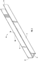
- FIG. 2 illustrates an embodiment of a retrofit kit 30 .
- retrofit kit 30 includes a first profile 51 , extending longitudinally, and a second profile 52 extending longitudinally.
- First profile 51 and second profile 52 may include a plurality of apertures, for example, 70 a and 70 b , for attachment to base 12 of fixture 10 .
- FIGS. 3 and 4 are illustrations of an assembled LED retrofit kit.
- retrofit kit 30 includes a first profile 51 , extending longitudinally, and a second profile 52 extending longitudinally.
- first profile 51 and second profile 52 are separate.
- a lens 66 is illustrated as attached to first profile and second profile, such as by an endcap or clip, for example, 72 (shown in FIG. 7 ).
- first profile 51 and second profile 52 may include one or more longitudinal ribs, for example, 59 , complimenting and corresponding to one or more endcap ribs.
- Second profile 52 is illustrated as attached to first longitudinal side 14 of base 12 of fixture 10 .
- FIG. 4 is an illustration of an assembled LED retrofit kit.
- Fixture 10 which includes second electrical receptacle 22 , is illustrated in phantom.
- First profile 51 is illustrated as attached to first longitudinal side 14 of base 12 of fixture 10 .
- Power supply 64 is illustrated as residing within raceway 62 and endcap 72 is shown in place upon the assembly.
- FIG. 5 is a perspective view of an endcap 72 , for use with one embodiment of the present ceiling light LED retrofit kit.
- a plurality of light panels 40 may be disposed end to end in electrical series, for particular advantages.
- a splice 74 may be used at the juncture of any two abutting light panels 40 .
- An embodiment of a splice 74 is depicted in FIG. 6 .
- FIG. 7 is a perspective view of an endcap 72 , for use with one embodiment the present ceiling light LED retrofit kit.
- endcap 72 includes one or more ribs that correspond the one or more longitudinal ribs, for example, 59 , along the first profile 51 and the second profile 52 , respectively.
- a plurality of light panels 40 may be disposed end to end in electrical series, for particular advantages.
- a splice 74 may be used at the juncture of any two abutting light panels 40 .
- An embodiment of a splice 74 is depicted in FIG. 8 .
- the splice may include one or more corresponding ribs, for example, 59 a and 59 b , that correspond to the one or more longitudinal ribs, for example, 59 , along the first profile 51 and the second profile 52 , respectively.
- the present invention further contemplates a method for retrofitting pre-installed fixtures or bases using the kit described herein.
- the method may include the steps of: 1) identifying a fixture having a pre-installed base having a first longitudinal side and a second longitudinal side; 2) providing a ceiling light LED retrofit kit comprising: a first profile, an opposing second profile, and a light panel, the light panel being disposed between the first profile and the opposing second profile; 3) connecting the first profile to the first longitudinal side, and the second profile to the second longitudinal side of the pre-installed base; 4) providing a light emitting diode and electrically connecting it to the light panel; and 5) covering the light panel with a lens.
- the ceiling light LED retrofit kit of the present invention offers several advantages, efficiencies, and optimizations. Because it is attached to an old fluorescent light fixture, added rigidity and strength is accomplished. For that reason, for example, thinner material may be used with first profile 51 and/or second profile 52 , achieving material costs savings, yet providing sufficient structural strength. Similarly, because the present ceiling light retrofit kit does not require disassembly of the first, second, and so forth electrical receptacles 21 , 22 of the earlier fixture 10 , labor and disposal costs are avoided. (Such electrical receptacles are sometimes referred to as “tombstones” by those with skill in this technology).
- the finished assembly of the within ceiling light LED retrofit kit includes a lens, rather than a previously-exposed linear fluorescent light tubes, providing a more attractive appearance and also enabling the user to provide custom refraction from the light illuminating from light emitting diode 60 , as may be desired in particular applications.
Landscapes
- Engineering & Computer Science (AREA)
- General Engineering & Computer Science (AREA)
- Physics & Mathematics (AREA)
- Microelectronics & Electronic Packaging (AREA)
- Optics & Photonics (AREA)
- Non-Portable Lighting Devices Or Systems Thereof (AREA)
Abstract
Description
Claims (28)
Priority Applications (4)
| Application Number | Priority Date | Filing Date | Title |
|---|---|---|---|
| US16/546,729 US10837628B2 (en) | 2016-02-24 | 2019-08-21 | Ceiling light LED retrofit kit with light panel defining a raceway disposed in between existing light fixture tombstones |
| US17/023,506 US11649952B2 (en) | 2016-02-24 | 2020-09-17 | Ceiling light LED retrofit kit |
| US18/130,531 US11953183B2 (en) | 2016-02-24 | 2023-04-04 | Ceiling light LED retrofit kit |
| US18/629,651 US12529469B2 (en) | 2016-02-24 | 2024-04-08 | Ceiling light LED retrofit kit |
Applications Claiming Priority (3)
| Application Number | Priority Date | Filing Date | Title |
|---|---|---|---|
| US201662299295P | 2016-02-24 | 2016-02-24 | |
| US15/441,447 US10429041B2 (en) | 2016-02-24 | 2017-02-24 | Ceiling light retrofit kit having a light panel and two profiles to surround preexisting base of a light fixture |
| US16/546,729 US10837628B2 (en) | 2016-02-24 | 2019-08-21 | Ceiling light LED retrofit kit with light panel defining a raceway disposed in between existing light fixture tombstones |
Related Parent Applications (1)
| Application Number | Title | Priority Date | Filing Date |
|---|---|---|---|
| US15/441,447 Continuation US10429041B2 (en) | 2016-02-24 | 2017-02-24 | Ceiling light retrofit kit having a light panel and two profiles to surround preexisting base of a light fixture |
Related Child Applications (1)
| Application Number | Title | Priority Date | Filing Date |
|---|---|---|---|
| US17/023,506 Continuation US11649952B2 (en) | 2016-02-24 | 2020-09-17 | Ceiling light LED retrofit kit |
Publications (2)
| Publication Number | Publication Date |
|---|---|
| US20190390843A1 US20190390843A1 (en) | 2019-12-26 |
| US10837628B2 true US10837628B2 (en) | 2020-11-17 |
Family
ID=59631007
Family Applications (5)
| Application Number | Title | Priority Date | Filing Date |
|---|---|---|---|
| US15/441,447 Active 2038-01-14 US10429041B2 (en) | 2016-02-24 | 2017-02-24 | Ceiling light retrofit kit having a light panel and two profiles to surround preexisting base of a light fixture |
| US16/546,729 Expired - Fee Related US10837628B2 (en) | 2016-02-24 | 2019-08-21 | Ceiling light LED retrofit kit with light panel defining a raceway disposed in between existing light fixture tombstones |
| US17/023,506 Active US11649952B2 (en) | 2016-02-24 | 2020-09-17 | Ceiling light LED retrofit kit |
| US18/130,531 Active US11953183B2 (en) | 2016-02-24 | 2023-04-04 | Ceiling light LED retrofit kit |
| US18/629,651 Active US12529469B2 (en) | 2016-02-24 | 2024-04-08 | Ceiling light LED retrofit kit |
Family Applications Before (1)
| Application Number | Title | Priority Date | Filing Date |
|---|---|---|---|
| US15/441,447 Active 2038-01-14 US10429041B2 (en) | 2016-02-24 | 2017-02-24 | Ceiling light retrofit kit having a light panel and two profiles to surround preexisting base of a light fixture |
Family Applications After (3)
| Application Number | Title | Priority Date | Filing Date |
|---|---|---|---|
| US17/023,506 Active US11649952B2 (en) | 2016-02-24 | 2020-09-17 | Ceiling light LED retrofit kit |
| US18/130,531 Active US11953183B2 (en) | 2016-02-24 | 2023-04-04 | Ceiling light LED retrofit kit |
| US18/629,651 Active US12529469B2 (en) | 2016-02-24 | 2024-04-08 | Ceiling light LED retrofit kit |
Country Status (2)
| Country | Link |
|---|---|
| US (5) | US10429041B2 (en) |
| WO (1) | WO2017147385A1 (en) |
Cited By (1)
| Publication number | Priority date | Publication date | Assignee | Title |
|---|---|---|---|---|
| US11649952B2 (en) | 2016-02-24 | 2023-05-16 | Power Concepts, Llc | Ceiling light LED retrofit kit |
Families Citing this family (5)
| Publication number | Priority date | Publication date | Assignee | Title |
|---|---|---|---|---|
| USD835826S1 (en) * | 2017-04-04 | 2018-12-11 | Lacks Home Products | Modular deck light |
| USD835824S1 (en) * | 2017-04-04 | 2018-12-11 | Lacks Home Products | Modular deck light |
| USD835825S1 (en) * | 2017-04-04 | 2018-12-11 | Lacks Home Products | Modular deck light |
| USD835822S1 (en) * | 2017-04-04 | 2018-12-11 | Lacks Home Products | Modular deck light |
| USD835823S1 (en) * | 2017-04-04 | 2018-12-11 | Lacks Home Products | Modular deck light |
Citations (7)
| Publication number | Priority date | Publication date | Assignee | Title |
|---|---|---|---|---|
| US6739743B2 (en) | 2001-06-27 | 2004-05-25 | Ichikoh Industries, Ltd. | Lamp device for vehicles, and combination of vehicle body and lamp device |
| US20070165399A1 (en) | 2006-01-05 | 2007-07-19 | Canlyte Inc. | Light Fixture and Assembly |
| US20100289428A1 (en) | 2009-05-12 | 2010-11-18 | Advanced Control Technologies, Inc. | Controllable Retroffited LED Panel Lighting |
| US8272763B1 (en) | 2009-10-02 | 2012-09-25 | Genesis LED Solutions | LED luminaire |
| US8696154B2 (en) | 2011-08-19 | 2014-04-15 | Lsi Industries, Inc. | Luminaires and lighting structures |
| US9163794B2 (en) * | 2012-07-06 | 2015-10-20 | Ilumisys, Inc. | Power supply assembly for LED-based light tube |
| US9307598B2 (en) | 2014-01-02 | 2016-04-05 | Lightel Technologies, Inc. | LED lighting device with replaceable driver-control module |
Family Cites Families (53)
| Publication number | Priority date | Publication date | Assignee | Title |
|---|---|---|---|---|
| US2981829A (en) | 1960-01-08 | 1961-04-25 | Globe Illumination Company | Recessed fluorescent troffer |
| US3673402A (en) | 1970-10-19 | 1972-06-27 | Harvey I Weiss | Extendible lighting fixture |
| US7038399B2 (en) | 2001-03-13 | 2006-05-02 | Color Kinetics Incorporated | Methods and apparatus for providing power to lighting devices |
| US6776504B2 (en) | 2001-07-25 | 2004-08-17 | Thomas C. Sloan | Perimeter lighting apparatus |
| US6860628B2 (en) | 2002-07-17 | 2005-03-01 | Jonas J. Robertson | LED replacement for fluorescent lighting |
| US7507001B2 (en) | 2002-11-19 | 2009-03-24 | Denovo Lighting, Llc | Retrofit LED lamp for fluorescent fixtures without ballast |
| US7296911B2 (en) | 2002-11-30 | 2007-11-20 | Genlyte Thomas Group, Llc | Surface mount fluorescent strip light fixture retrofit kit and method |
| US6739734B1 (en) | 2003-03-17 | 2004-05-25 | Ultimate Presentation Sytems, Inc. | LED retrofit method and kit for converting fluorescent luminaries |
| US7344279B2 (en) | 2003-12-11 | 2008-03-18 | Philips Solid-State Lighting Solutions, Inc. | Thermal management methods and apparatus for lighting devices |
| US20060221606A1 (en) | 2004-03-15 | 2006-10-05 | Color Kinetics Incorporated | Led-based lighting retrofit subassembly apparatus |
| CN2766345Y (en) | 2005-02-21 | 2006-03-22 | 陈仕群 | LED lighting lamp tube |
| US7661229B2 (en) | 2005-05-12 | 2010-02-16 | Worthington Armstrong Venture | Electrical conductivity in a suspended ceiling system |
| US7311423B2 (en) | 2005-09-21 | 2007-12-25 | Awi Licensing Company | Adjustable LED luminaire |
| AU2006294475B2 (en) | 2005-09-28 | 2010-11-11 | Armstrong World Industries, Inc. | Power and signal distribution system for use in interior building spaces |
| US7351075B1 (en) | 2006-10-17 | 2008-04-01 | Awi Licensing Company | Electrified ceiling framework connectors |
| US7762821B2 (en) | 2006-10-17 | 2010-07-27 | Worthington Armstrong Venture | Electrified ceiling framework |
| TWM314823U (en) | 2006-12-29 | 2007-07-01 | Edison Opto Corp | Light emitting diode light tube |
| US7936129B2 (en) | 2007-04-05 | 2011-05-03 | Eco Lighting Llc | Lighting conversion system |
| US20080266849A1 (en) | 2007-04-30 | 2008-10-30 | Nielson Lyman O | Fluorescent lighting conversion to led lighting using a power converter |
| US7614195B2 (en) | 2007-08-27 | 2009-11-10 | Worthington Armstrong Venture | Suspended ceiling grid network utilizing seismic separation joint clips |
| WO2009128909A1 (en) | 2008-04-15 | 2009-10-22 | Armstrong World Industries, Inc. | Connectors for electrically active grid |
| CN102318149B (en) | 2008-12-19 | 2014-05-28 | 威福公司 | Internal bus bars and electrical interconnections between them |
| US20100315001A1 (en) | 2009-06-11 | 2010-12-16 | Domagala Thomas W | Light emitting diode devices configured as a replacement to linear fluorescent tube devices |
| WO2011008684A2 (en) | 2009-07-13 | 2011-01-20 | Smashray, Ltd. | Light emitting diode retrofit conversion kit for a fluorescent light fixture |
| US9243759B2 (en) | 2009-10-08 | 2016-01-26 | I/O Controls Corporation | LED-based lighting system for retrofitting fluorescent lighting fixtures in a transit vehicle |
| US8896208B2 (en) | 2009-12-31 | 2014-11-25 | Larry N. Shew | Light assembly |
| US8616720B2 (en) | 2010-04-27 | 2013-12-31 | Cooper Technologies Company | Linkable linear light emitting diode system |
| CA2762143C (en) * | 2010-12-16 | 2014-08-12 | Abl Ip Holding, Llc | Led lighting assembly for fluorescent light fixtures |
| JP5714996B2 (en) | 2011-07-12 | 2015-05-07 | 株式会社ヴァレオジャパン | Rotating connector device |
| CN102913773B (en) | 2011-08-02 | 2016-05-04 | 欧司朗股份有限公司 | LED luminescence component and there is the LED remodeling lamp of this LED luminescence component |
| US8727566B1 (en) * | 2011-09-26 | 2014-05-20 | Oliver Szeto | Assembly and method for retrofitting LED lights into a fluorescent bulb ceiling fixture |
| US8905621B2 (en) | 2011-11-30 | 2014-12-09 | Osram Sylvania Inc. | Luminaire adapter with tombstone cover |
| US20140168961A1 (en) | 2012-12-18 | 2014-06-19 | Jack Guy Dubord | Retrofit kit for fluorescent lamp fixtures |
| US9146024B2 (en) | 2013-02-20 | 2015-09-29 | SEVLights | LED lighting module, LED lighting system and LED lighting retrofit kit |
| US9874333B2 (en) * | 2013-03-14 | 2018-01-23 | Cree, Inc. | Surface ambient wrap light fixture |
| US9243757B2 (en) | 2013-05-02 | 2016-01-26 | Lunera Lighting, Inc. | Retrofit LED lighting system for replacement of fluorescent lamp |
| KR102070096B1 (en) | 2013-06-27 | 2020-01-29 | 삼성전자주식회사 | Light source module and lighting device having the same |
| US9169977B2 (en) * | 2013-06-28 | 2015-10-27 | Cree, Inc. | LED lamp |
| US9380654B2 (en) | 2013-07-11 | 2016-06-28 | General Electric Company | Light emitting diode (LED) lamp replacement driver for linear fluorescent lamps |
| US9702531B2 (en) | 2014-04-23 | 2017-07-11 | General Led, Inc. | Retrofit system and method for replacing linear fluorescent lamp with LED modules |
| US10415773B2 (en) | 2014-05-27 | 2019-09-17 | Osram Sylvania Inc. | Elongated solid state light source holder for retrofitting luminaires with tombstone sockets |
| US9822937B2 (en) | 2014-06-16 | 2017-11-21 | Abl Ip Holding Llc | Light engine retrofit kit and method for installing same |
| CN105526563A (en) | 2014-09-30 | 2016-04-27 | 通用电气照明解决方案有限公司 | Connector and LED lighting device using such connector |
| CN105698064B (en) | 2014-11-28 | 2019-02-01 | 通用电气照明解决方案有限公司 | The repacking external member and method of modifying of recessed light fixture |
| MX393990B (en) | 2014-12-18 | 2025-03-24 | Armstrong World Ind Inc | INTEGRATED ROOFING AND LIGHTING SYSTEM. |
| US9550401B2 (en) | 2015-04-13 | 2017-01-24 | Reyco Granning, Llc | IFS including strut pivotally secured to chassis through torque tube assembly |
| US9845596B2 (en) | 2015-09-29 | 2017-12-19 | Awi Licensing Llc | Ceiling system |
| US9726332B1 (en) | 2016-02-09 | 2017-08-08 | Michael W. May | Networked LED lighting system |
| WO2017147385A1 (en) | 2016-02-24 | 2017-08-31 | Power Concepts, Llc | Ceiling light led retrofit kit |
| US10288240B2 (en) | 2016-06-23 | 2019-05-14 | Metaphase Technologies, Inc. | System and method for covering a fluorescent ceiling fixture with a matrix of LED lights |
| CN106366630A (en) | 2016-08-31 | 2017-02-01 | 上海新力动力设备研究所 | Liner material for improving interfacial bonding of HTPB propellant and preparation method thereof |
| US10807524B2 (en) | 2016-11-18 | 2020-10-20 | Saf-T-Glo Limited | Lighting unit |
| US10408394B2 (en) | 2017-02-01 | 2019-09-10 | Current Lighting Solutions, Llc | LED retrofit lighting apparatus for a light fixture |
-
2017
- 2017-02-24 WO PCT/US2017/019303 patent/WO2017147385A1/en not_active Ceased
- 2017-02-24 US US15/441,447 patent/US10429041B2/en active Active
-
2019
- 2019-08-21 US US16/546,729 patent/US10837628B2/en not_active Expired - Fee Related
-
2020
- 2020-09-17 US US17/023,506 patent/US11649952B2/en active Active
-
2023
- 2023-04-04 US US18/130,531 patent/US11953183B2/en active Active
-
2024
- 2024-04-08 US US18/629,651 patent/US12529469B2/en active Active
Patent Citations (7)
| Publication number | Priority date | Publication date | Assignee | Title |
|---|---|---|---|---|
| US6739743B2 (en) | 2001-06-27 | 2004-05-25 | Ichikoh Industries, Ltd. | Lamp device for vehicles, and combination of vehicle body and lamp device |
| US20070165399A1 (en) | 2006-01-05 | 2007-07-19 | Canlyte Inc. | Light Fixture and Assembly |
| US20100289428A1 (en) | 2009-05-12 | 2010-11-18 | Advanced Control Technologies, Inc. | Controllable Retroffited LED Panel Lighting |
| US8272763B1 (en) | 2009-10-02 | 2012-09-25 | Genesis LED Solutions | LED luminaire |
| US8696154B2 (en) | 2011-08-19 | 2014-04-15 | Lsi Industries, Inc. | Luminaires and lighting structures |
| US9163794B2 (en) * | 2012-07-06 | 2015-10-20 | Ilumisys, Inc. | Power supply assembly for LED-based light tube |
| US9307598B2 (en) | 2014-01-02 | 2016-04-05 | Lightel Technologies, Inc. | LED lighting device with replaceable driver-control module |
Cited By (2)
| Publication number | Priority date | Publication date | Assignee | Title |
|---|---|---|---|---|
| US11649952B2 (en) | 2016-02-24 | 2023-05-16 | Power Concepts, Llc | Ceiling light LED retrofit kit |
| US12529469B2 (en) | 2016-02-24 | 2026-01-20 | Power Concepts, Llc | Ceiling light LED retrofit kit |
Also Published As
| Publication number | Publication date |
|---|---|
| US20210003268A1 (en) | 2021-01-07 |
| US11649952B2 (en) | 2023-05-16 |
| WO2017147385A1 (en) | 2017-08-31 |
| US10429041B2 (en) | 2019-10-01 |
| US20230265995A1 (en) | 2023-08-24 |
| US20240255125A1 (en) | 2024-08-01 |
| US20190390843A1 (en) | 2019-12-26 |
| US12529469B2 (en) | 2026-01-20 |
| US11953183B2 (en) | 2024-04-09 |
| US20170241600A1 (en) | 2017-08-24 |
Similar Documents
| Publication | Publication Date | Title |
|---|---|---|
| US10837628B2 (en) | Ceiling light LED retrofit kit with light panel defining a raceway disposed in between existing light fixture tombstones | |
| US8955998B2 (en) | Lighting assembly for ceiling board | |
| US6585396B1 (en) | Fluorescent hanging light fixture | |
| US8206004B2 (en) | Distributed lighting apparatus | |
| US20160320553A1 (en) | Edge-Lit Light Guide Panel | |
| US5249112A (en) | Configurable lighting system | |
| KR101753613B1 (en) | Prefabricated ceiling lights | |
| US11396998B2 (en) | Mechanical and electric connection apparatus for continuous run luminaires | |
| WO2011106695A1 (en) | Led lighting element | |
| US10107460B2 (en) | Method and system for retrofitting luminaires | |
| US10788162B2 (en) | Retrofit kit and methods for conversion of fluorescent light assemblies to LED assemblies | |
| US10451230B2 (en) | Wall mount light fixture | |
| US11098880B2 (en) | Luminaire with improved assembly, installation, and wireless functionality | |
| US20100172141A1 (en) | Shop light fixture | |
| KR101037404B1 (en) | Ceiling LED lighting by extruded main body | |
| WO2014042506A1 (en) | Light bar assembly and its mounting arrangement | |
| KR20220063926A (en) | LED Lighting Apparatus | |
| CN218468894U (en) | Equidistant light distribution lamp | |
| KR200499071Y1 (en) | Ceiling buried lights using LED | |
| KR102859443B1 (en) | Ceiling edge lighting that creates side decorative light | |
| CN213927030U (en) | Grille decoration strip | |
| KR200389278Y1 (en) | Space coupler of fluorescent lamp facility | |
| KR200389277Y1 (en) | Space coupler of fluorescent lamp facility | |
| KR200427937Y1 (en) | Fixture structure of lighting lamp and lighting fixture using the same | |
| TWM619651U (en) | Long tubular LED lamp dustproof lamp holder device |
Legal Events
| Date | Code | Title | Description |
|---|---|---|---|
| FEPP | Fee payment procedure |
Free format text: ENTITY STATUS SET TO UNDISCOUNTED (ORIGINAL EVENT CODE: BIG.); ENTITY STATUS OF PATENT OWNER: SMALL ENTITY |
|
| FEPP | Fee payment procedure |
Free format text: ENTITY STATUS SET TO SMALL (ORIGINAL EVENT CODE: SMAL); ENTITY STATUS OF PATENT OWNER: SMALL ENTITY |
|
| AS | Assignment |
Owner name: POWER CONCEPTS, LLC, SOUTH CAROLINA Free format text: ASSIGNMENT OF ASSIGNORS INTEREST;ASSIGNORS:BEATENBOUGH, BRYAN;HALEY, RYAN;REEL/FRAME:050411/0121 Effective date: 20190909 |
|
| STPP | Information on status: patent application and granting procedure in general |
Free format text: DOCKETED NEW CASE - READY FOR EXAMINATION |
|
| STPP | Information on status: patent application and granting procedure in general |
Free format text: NON FINAL ACTION MAILED |
|
| STPP | Information on status: patent application and granting procedure in general |
Free format text: NOTICE OF ALLOWANCE MAILED -- APPLICATION RECEIVED IN OFFICE OF PUBLICATIONS |
|
| STPP | Information on status: patent application and granting procedure in general |
Free format text: PUBLICATIONS -- ISSUE FEE PAYMENT VERIFIED |
|
| STCF | Information on status: patent grant |
Free format text: PATENTED CASE |
|
| IPR | Aia trial proceeding filed before the patent and appeal board: inter partes review |
Free format text: TRIAL NO: IPR2022-00534 Opponent name: CURRENT LIGHTING SOLUTIONS, LLC, AND WALMART, INC. Effective date: 20220204 |
|
| DC | Disclaimer filed |
Free format text: DISCLAIM THE FOLLOWING COMPLETE CLAIMS 15, 16, 17 OF SAID Effective date: 20220622 |
|
| IPRC | Trial and appeal board: inter partes review certificate |
Kind code of ref document: K1 Free format text: INTER PARTES REVIEW CERTIFICATE; TRIAL NO. IPR2022-00534, FEB. 4, 2022 INTER PARTES REVIEW CERTIFICATE FOR PATENT 10,837,628, ISSUED NOV. 17, 2020, APPL. NO. 16/546,729, AUG. 21, 2019 INTER PARTES REVIEW CERTIFICATE ISSUED DEC. 1, 2023 Effective date: 20231201 |
|
| LAPS | Lapse for failure to pay maintenance fees |
Free format text: PATENT EXPIRED FOR FAILURE TO PAY MAINTENANCE FEES (ORIGINAL EVENT CODE: EXP.); ENTITY STATUS OF PATENT OWNER: SMALL ENTITY |
|
| STCH | Information on status: patent discontinuation |
Free format text: PATENT EXPIRED DUE TO NONPAYMENT OF MAINTENANCE FEES UNDER 37 CFR 1.362 |
|
| FP | Lapsed due to failure to pay maintenance fee |
Effective date: 20241117 |