US10834481B2 - Audio rack/chassis and patchbay device - Google Patents
Audio rack/chassis and patchbay device Download PDFInfo
- Publication number
- US10834481B2 US10834481B2 US16/046,890 US201816046890A US10834481B2 US 10834481 B2 US10834481 B2 US 10834481B2 US 201816046890 A US201816046890 A US 201816046890A US 10834481 B2 US10834481 B2 US 10834481B2
- Authority
- US
- United States
- Prior art keywords
- chassis
- bays
- analog
- outputs
- rack
- Prior art date
- Legal status (The legal status is an assumption and is not a legal conclusion. Google has not performed a legal analysis and makes no representation as to the accuracy of the status listed.)
- Active
Links
Images


Classifications
-
- H—ELECTRICITY
- H04—ELECTRIC COMMUNICATION TECHNIQUE
- H04Q—SELECTING
- H04Q1/00—Details of selecting apparatus or arrangements
- H04Q1/02—Constructional details
- H04Q1/13—Patch panels for monitoring, interconnecting or testing circuits, e.g. patch bay, patch field or jack field; Patching modules
-
- H—ELECTRICITY
- H04—ELECTRIC COMMUNICATION TECHNIQUE
- H04Q—SELECTING
- H04Q1/00—Details of selecting apparatus or arrangements
- H04Q1/02—Constructional details
- H04Q1/025—Cabinets
-
- H—ELECTRICITY
- H04—ELECTRIC COMMUNICATION TECHNIQUE
- H04Q—SELECTING
- H04Q1/00—Details of selecting apparatus or arrangements
- H04Q1/02—Constructional details
- H04Q1/06—Cable ducts or mountings specially adapted for exchange installations
- H04Q1/066—Cable ducts or mountings specially adapted for exchange installations arranged on the front side
-
- H—ELECTRICITY
- H04—ELECTRIC COMMUNICATION TECHNIQUE
- H04Q—SELECTING
- H04Q1/00—Details of selecting apparatus or arrangements
- H04Q1/02—Constructional details
- H04Q1/09—Frames or mounting racks not otherwise provided for
-
- H—ELECTRICITY
- H04—ELECTRIC COMMUNICATION TECHNIQUE
- H04Q—SELECTING
- H04Q2201/00—Constructional details of selecting arrangements
- H04Q2201/10—Housing details
Definitions
- aspects of the present disclosure involve signal processing devices and systems, and in particular, devices and systems that receive various audio inputs and output various audio outputs involving audio signals.
- a patchbay also called a patch panel or breakout panel
- a patchbay is a panel that provides cable connections for flexible signal routing between various devices (e.g., audio devices) and equipment. More specifically, cables connect to devices (e.g. jacks) at both front and rear faces of the patchbay thereby enabling connections to be dynamically established or broken between devices.
- Patchbay devices are typically arranged so that a number of circuits, usually of the same or similar type, appear on jacks for monitoring, interconnecting, and testing circuits in a convenient, flexible manner.
- a 500 Series rack (also called a chassis) is a centralized box device that provides power and input/output routing for 500 Series form factor audio modules.
- 500 Series racks enable consumers to use specific audio modules that were typically only available in large audio console desks and rack mountable equipment.
- the 500 Series rack is designed to provide the power and input/output to smaller modules that provide functions similar or equivalent to the modules normally received from the larger consoles or rack units.
- FIG. 1A is a front view of a rack/chassis, according to aspects of the present disclosure.
- FIG. 1B is a rear view of a rack/chassis, according to aspects of the present disclosure.
- FIG. 2 is a schematic of a module that may be installed in a rack/chassis, according to aspects of the present disclosure.
- FIG. 3 is a block diagram illustrating connections between rack/chassis module slots and built in patchbay jacks, according to aspects of the present disclosure.
- FIG. 4 is a schematic of a patchbay mult wiring diagram, according to aspects of the present disclosure.
- FIG. 5 is schematic of a Patchbay Rack 8 illustrating connections between rack/chassis module slots and built in patchbay jacks, according to aspects of the present disclosure.
- an audio signal processing system (digital and/or analog) that includes various audio signal inputs and outputs for producing distributed audio signals for use in audio processing and related applications.
- the digital and/or analog audio signal processing system includes a rack/chassis containing a central routing card, a plurality of slots for receiving input cards (e.g., 500 Series cards) referred to herein as “modules”, and a plurality of outputs for receiving and producing various processed audio signal outputs.
- the digital and/or analog audio signal processing system further includes a plurality of integrated power supply components and full set of connectors (e.g., XLR connectors) to enable the various inputs and outputs.
- the disclosed audio signal processing system may combine the function of a typical 500 Series rack/chassis, such as a Lunchbox® designed by API, with the functionality of a patchbay(s).
- a 500 Series rack is a system for mounting compact modules into a tabletop or rack-mountable chassis.
- a typical 500 Series rack/chassis may include: 6-8 slots (commonly referred to as “bays”) for receiving modules; DB-25 (D-Sub) connectors for input/output; one or more universal power supplies (e.g., 100-250V, 47 to 63 Hz); and mechanisms for enabling easy rack-mounting.
- a patchbay (also called a panel) is a device that provides or otherwise enables cable connections for routing signals between devices. More specifically, cables connect to devices (e.g., jacks) at front and rear panels of the patchbay. The devices are configured to enable a plurality of circuits to appear on jacks for monitoring, interconnecting, testing, etc., in a flexible manner. For example, patchbays are typically used to allow audio technicians to change the path of select signals, without the use of dedicated switching equipment.
- a user in order to fully employ a patchbay, a user must choose the pieces of audio equipment he/she wants to be hard-wired to the patchbay, choose the correct I/O connections for each piece of unique gear, and have those connections installed onto one end of the cabling being used to wire the patchbay. The user would then need to connect the other end of the cable to the patchbay through soldering individual connections, large form connectors or punchblocks, etc.
- a patchbay allows for the dynamic routing of signals between inputs and outputs of devices statically wired to it, and traditionally requires an end user to spend a significant amount of time and money to obtain and install it.
- the front panel of a patchbay consists of rows of jacks that can be connected together using “patch cables.”
- the back panel of a patchbay consists of solder posts, punch blocks, or various types of jacks that are statically wired to devices that an end user may want to connect together, or “patch.”
- the patchbay's front panel jacks and rear panel posts/jacks are connected internally, thus, all of the devices' inputs and outputs that are statically wired to the back panel posts/jacks of the patchbay are conveniently located and accessible in one place, the front panel jacks of the patchbay, and may be “patched” together using patch cables.
- an external patchbay wired to a 500 Series rack/chassis functions identically to a 500 Series rack/chassis fitted with a built-in patchbay, however, a 500 Series rack/chassis fitted with a built-in patchbay is a more attractive solution for adding flexible signal routing between modules in a 500 Series setup and external devices for the following reasons: an external patchbay is expensive to purchase in addition to a 500 Series rack/chassis; an external patchbay requires very expensive cabling & connectors in addition to the patchbay itself; an external patchbay requires a significant amount of time to hook up and install; and an external patchbay is not a mobile-friendly solution for signal routing between 500 Series devices.
- a 500 Series rack/chassis fitted with a built-in patchbay does not suffer from any of the abovementioned issues associated with an external patchbay wired to a 500 Series rack/chassis.
- an external patchbay undermines key advantages of the 500 Series format, which offers a standard for small footprint, low cost, mobile-friendly gear. Therefore, a 500 Series rack/chassis fitted with a built-in patchbay provides for much-needed, flexible signal routing in a convenient, affordable, and mobile manner that's consistent with the design standards of the 500 Series format.
- the present disclosure solves these technical issues, and others, by describing an audio signal processing system and/or device or apparatus that marries or otherwise couples the functionality and usability of a typical 500 Series rack/chassis and the functionality and usability of a patchbay into a single apparatus and/or device.
- the audio signal processing system 100 comprises a rack/chassis 102 having a front-facing panel 109 containing a plurality of slots 103 for receiving and securing a plurality of modules (e.g., printed circuit boards).
- each slot 103 may have mechanical guides 150 for receiving at least one module, such as a signal processing card, among other types of audio modules.
- each slot 103 may not require mechanical guides and thus a module may simply be directly inserted into a given slot 103 .
- each slot 103 may receive a power supply, although the power supply may be located elsewhere within or outside of the audio signal processing system or device 100 .
- FIG. 2 illustrates an example module 200 that may be inserted into one of the slots 103 of the rack/chassis 102 .
- the module 200 is able to be inserted into connectors 106 of the slots 103 .
- the rack/chassis 102 may be mounted in a standard audio equipment rack and is designed to accept the various modules (e.g., module 200 ) into their respective slots 103 , where electrical connections (e.g., incoming and outgoing) for use in audio processing are made.
- the rack/chassis 102 is constructed with eight slots 103 to house eight modules (e.g., eight of the modules 200 ).
- the rack/chassis 102 may be constructed with enough slots 103 to house a varying number of modules 200 that include more or less than eight.
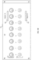
- FIG. 1B illustrates a rear panel 121 of the rack/chassis 102 , according to aspects of the present disclosure.
- the rear panel 121 includes various input and/or outputs, including a plurality of XLR jacks and DB25 connectors (illustrated as connections 1 - 8 ).
- the rear panel 121 provides access to the inputs and outputs for each module 200 loaded into each slot 103 .
- the rear panel 121 has 16 XLR jacks, each of which feature an XLR connection.
- the jacks are illustrated in two sections: an output section 115 with jacks 1 - 8 , and an input section 116 with jacks 1 - 8 .
- the rear panel 121 also includes two DB25 connectors 120 and 122 .
- the front-facing panel 109 of the rack/chassis 102 includes a series of outputs 130 , a series of inputs 132 , and a series of mult jacks 134 .
- a “mult” accepts a single instance of a signal as its input, and outputs multiple instances of the signal.
- a mult connection allows an end user to process and/or use the multiple instances of a signal in various ways.
- the series of outputs 130 , series of inputs 132 , and series of mult connections 134 are built directly into the rack/chassis 102 and function as a typical patchbay (e.g., similar or the same as an external patchbay).
- the series of outputs 130 , series of inputs 132 , and series of mult connections 134 on the rack/chassis 102 are connected to the various XLR and DB25 inputs and outputs on the back plate or rear panel 121 , as well as the I/O of each module connector 106 , which enables modules contained within a given slot 103 to be connected together or patched, thereby enabling the routing of a plurality of electrical signals to and from various audio equipment and devices.
- FIG. 3 illustrates an example block diagram 300 illustrating connections between rack/chassis module slots and the various jacks and connections that function as a patchbay.
- a module slot connector 310 (similar to connector 106 ) is connected or otherwise wired to a male XLR output jack 302 , which is connected to a female DB25 output jack 304 , which is connected to a female TT output jack 306 .
- the module slot connector 310 is connected to a female XLR input jack 312 , which is connected to a female DB25 input jack 314 , which is connected to a female TT input jack 316 .
- the module slot connector 310 may also be connected to a power supply 308 .
- the female TT jacks (e.g., 306 and 316 ) may be all or part of the mult(s) 134 .
- FIG. 4 is a wire schematic 400 of part of a patchbay directly integrated into a 500 Series rack, illustrating mult connections 402 and 404 that split signals for use in parallel signal processing and routing. As illustrated, an input jack receives an audio signal and routes the signal to two output jacks, effectively providing an end user with two instances of the same signal.
- FIG. 5 is a wire schematic 500 of a patchbay directly integrated into a 500 Series rack, illustrating connections between rack/chassis slots, various built in patchbay jacks, various back panel jacks, and module slot power rails. As illustrated, these connections make possible the integration of an external patchbay into a 500 Series rack/chassis without the need for additional wiring or connectors between the 500 Series rack/chassis and patchbay.
- FIG. 5 illustrates a single balanced input and output connection of a 500 Series rack/chassis with an integrated patchbay. Also shown is the power connection 520 from a 500 Series rack/chassis power supply to a 500 Series rack/chassis slot connector 502 .
- a common balanced audio connection is made up of 3 signals: + or hot, ⁇ or cold, and ground or GND (as illustrated at the various connections).
- the balanced output is an unbroken connection between the 500 Series rack/chassis slot connector 502 , Male XLR jack 504 , Female DB25 Output jack 506 , and a Female TT Output jack 508 .
- the balanced input is an unbroken connection between the Female XLR Input jack 510 , Female DB25 Input jack 512 , a Female TT Input jack 514 , as well as an unbroken connection between the Female TT Input jack and the 500 Series chassis/rack slot connector 502 .
- the Female TT Input jack has a breakable connection that can disconnect the 500 Series rack/chassis slot connector 502 from the Female DB25 Input jack 512 and Female XLR Input jack 510 if a TT cable is plugged into the Female TT Input jack 514 .
- Power is distributed to a 500 Series rack/chassis slot connector through 4 separate connections, illustrated at 520 .
- the audio signal processing system disclosed herein and discussed above enables users to configure the system to generate a plurality of inputs and outputs respectively, and enables the user to configure various audio processing components, such as effects, compressors, equalizers, among others.
- the unique configuration of the audio signal processing system and/or device enables users to combine the functionality of a typical patchbay and the functionality of a typical rack/chassis (e.g., a 500 Series rack) into a single device.
- a 500 Series rack/chassis e.g., the rack/chassis 102
- a 500 Series Rack a 500 Series Auteur microphone preamp
- a 500 Series B12A microphone preamp a 500 Series equalizer
- a 500 Series compressor a 500 Series compressor
- a 500 Series reverb unit a 500 Series reverb unit.
- Each of these 500 Series modules has a different function in processing audio and the EQ, Compressor and Reverb (processor's) are interchangeable in their place in the chain.
- the recording interface takes analog audio and converts it to digital audio, which is fed to a computer for recording purposes.
- the signal chain will be:
- these devices will be semi-hard wired to the recording interface via the 500 Series rack back panel inputs and outputs.
- the user would have the modules loaded into the 500 Series rack and the cables daisy chained in and out of each module slot until the 3 rd processor, which would be semi-hard wired to an input of the recording interface.
- the B12A preamp is not being used, but is installed in the rack/chassis.
- the user likes this setup. However, at some point in the future, the user decides it would be beneficial to use the B12A as the microphone preamp instead of the Auteur. In a normal setup, the user would have to either access the back of the 500 Series rack to move the microphone cable from the Auteur to the B12A, or power the rack/chassis down completely, unscrew the holding screws, remove each module, and trade where each one is inserted in the rack/chassis.
- the user enjoys the new signal chain until he/she decides the Reverb is not working well anymore.
- the user will need to power down the 500 Series rack, move the gear cabinet out, and reach through the cluster of cables and change the cabling around to omit the Reverb.
- the user realizes that the EQ should be placed after the Compressor in the chain. Again, the user must either power down everything, unscrew each module and swap their placement, or move the gear cabinet out and rearrange the cabling from behind.
- the solution is the disclosed signal processing device and/or system that integrates an internal patchbay directly into the rack/chassis. Such a device allows the user to make any configuration of signal flow to and from 500 Series modules loaded into the rack possible.
- the I/O for each 500 module is available on the patchbay and is front and center in any gear cabinet. Signal chains can be quickly tried and discarded as fast as a user can plug cables into the patchbay.
Landscapes
- Engineering & Computer Science (AREA)
- Computer Networks & Wireless Communication (AREA)
- Details Of Connecting Devices For Male And Female Coupling (AREA)
- Circuit For Audible Band Transducer (AREA)
Abstract
Description
-
- Microphone-Preamp-Processor 1-Processor 2-Processor 3-Interface-Computer.
Claims (10)
Priority Applications (1)
| Application Number | Priority Date | Filing Date | Title |
|---|---|---|---|
| US16/046,890 US10834481B2 (en) | 2018-07-26 | 2018-07-26 | Audio rack/chassis and patchbay device |
Applications Claiming Priority (1)
| Application Number | Priority Date | Filing Date | Title |
|---|---|---|---|
| US16/046,890 US10834481B2 (en) | 2018-07-26 | 2018-07-26 | Audio rack/chassis and patchbay device |
Publications (2)
| Publication Number | Publication Date |
|---|---|
| US20200037051A1 US20200037051A1 (en) | 2020-01-30 |
| US10834481B2 true US10834481B2 (en) | 2020-11-10 |
Family
ID=69177258
Family Applications (1)
| Application Number | Title | Priority Date | Filing Date |
|---|---|---|---|
| US16/046,890 Active US10834481B2 (en) | 2018-07-26 | 2018-07-26 | Audio rack/chassis and patchbay device |
Country Status (1)
| Country | Link |
|---|---|
| US (1) | US10834481B2 (en) |
Citations (2)
| Publication number | Priority date | Publication date | Assignee | Title |
|---|---|---|---|---|
| US20160269134A1 (en) * | 2015-03-12 | 2016-09-15 | Nathan Malone | Audio Processing Device |
| US20170324494A1 (en) * | 2015-04-08 | 2017-11-09 | John Donald Tillman | Modular platform for creation and manipulation of audio and musical signals |
-
2018
- 2018-07-26 US US16/046,890 patent/US10834481B2/en active Active
Patent Citations (2)
| Publication number | Priority date | Publication date | Assignee | Title |
|---|---|---|---|---|
| US20160269134A1 (en) * | 2015-03-12 | 2016-09-15 | Nathan Malone | Audio Processing Device |
| US20170324494A1 (en) * | 2015-04-08 | 2017-11-09 | John Donald Tillman | Modular platform for creation and manipulation of audio and musical signals |
Also Published As
| Publication number | Publication date |
|---|---|
| US20200037051A1 (en) | 2020-01-30 |
Similar Documents
| Publication | Publication Date | Title |
|---|---|---|
| US7259325B2 (en) | High density front access device | |
| US7217152B1 (en) | Patch panel with tracer | |
| US6641411B1 (en) | Low cost high speed connector | |
| US10235314B2 (en) | Fabric for modular solid-state storage systems | |
| US4764849A (en) | Data bus distribution apparatus | |
| US10579574B2 (en) | Instrumentation chassis with high speed bridge board | |
| US20150327381A1 (en) | Rack mountable network switch | |
| US7685349B2 (en) | Modules and backplanes | |
| US5984732A (en) | Method and apparatus for interconnection of modular electronic components | |
| US5173845A (en) | High density frontplane interconnection system | |
| EP1707038B1 (en) | Interface enhancement for modular platform applications | |
| US4272141A (en) | Electronic card cage interfacing assembly | |
| US20140301060A1 (en) | High Density Digital Signal Cross-Connect System | |
| US7283374B2 (en) | Grow as you go equipment shelf | |
| US7257223B2 (en) | Splitter assembly for a telecommunications system | |
| US11177618B1 (en) | Server blind-mate power and signal connector dock | |
| US20020050384A1 (en) | Multimedia system with a housing that operationally stores a plurality of multimedia modules | |
| US6608761B2 (en) | Multiple processor cards accessing common peripherals via transparent and non-transparent bridges | |
| US10834481B2 (en) | Audio rack/chassis and patchbay device | |
| US7715208B2 (en) | Configurable multi-faceted input/output panel | |
| CA2270041C (en) | Patch panel with incorporated distribution amplifiers | |
| US20070077811A1 (en) | Integrated connector including both data and power signals | |
| US10126789B2 (en) | Transfer module and electronic device having the same | |
| EP0785706A1 (en) | Drawer for electronic cards with automatic plug-in and draw-out, drawer and its receptacie and method for dismounting electronic cards | |
| CN215006490U (en) | Industrial control machine |
Legal Events
| Date | Code | Title | Description |
|---|---|---|---|
| AS | Assignment |
Owner name: BLACK LION AUDIO CHICAGO, INC., ILLINOIS Free format text: ASSIGNMENT OF ASSIGNORS INTEREST;ASSIGNORS:BIERDEMAN, NATHANIEL T.;LARSON, DANIEL S.;REEL/FRAME:046639/0018 Effective date: 20180725 |
|
| FEPP | Fee payment procedure |
Free format text: ENTITY STATUS SET TO UNDISCOUNTED (ORIGINAL EVENT CODE: BIG.); ENTITY STATUS OF PATENT OWNER: SMALL ENTITY |
|
| FEPP | Fee payment procedure |
Free format text: ENTITY STATUS SET TO SMALL (ORIGINAL EVENT CODE: SMAL); ENTITY STATUS OF PATENT OWNER: SMALL ENTITY |
|
| STPP | Information on status: patent application and granting procedure in general |
Free format text: FINAL REJECTION MAILED |
|
| STPP | Information on status: patent application and granting procedure in general |
Free format text: NOTICE OF ALLOWANCE MAILED -- APPLICATION RECEIVED IN OFFICE OF PUBLICATIONS |
|
| STPP | Information on status: patent application and granting procedure in general |
Free format text: PUBLICATIONS -- ISSUE FEE PAYMENT VERIFIED |
|
| STCF | Information on status: patent grant |
Free format text: PATENTED CASE |
|
| FEPP | Fee payment procedure |
Free format text: SURCHARGE FOR LATE PAYMENT, SMALL ENTITY (ORIGINAL EVENT CODE: M2554); ENTITY STATUS OF PATENT OWNER: SMALL ENTITY |
|
| MAFP | Maintenance fee payment |
Free format text: PAYMENT OF MAINTENANCE FEE, 4TH YR, SMALL ENTITY (ORIGINAL EVENT CODE: M2551); ENTITY STATUS OF PATENT OWNER: SMALL ENTITY Year of fee payment: 4 |