US10833792B2 - Overlapped multiplexing-based modulation and demodulation method and device - Google Patents
Overlapped multiplexing-based modulation and demodulation method and device Download PDFInfo
- Publication number
- US10833792B2 US10833792B2 US16/379,744 US201916379744A US10833792B2 US 10833792 B2 US10833792 B2 US 10833792B2 US 201916379744 A US201916379744 A US 201916379744A US 10833792 B2 US10833792 B2 US 10833792B2
- Authority
- US
- United States
- Prior art keywords
- information
- coding
- check
- decoding
- log
- Prior art date
- Legal status (The legal status is an assumption and is not a legal conclusion. Google has not performed a legal analysis and makes no representation as to the accuracy of the status listed.)
- Expired - Fee Related
Links
- 238000000034 method Methods 0.000 title claims abstract description 80
- 230000015654 memory Effects 0.000 claims description 18
- 230000008054 signal transmission Effects 0.000 claims description 4
- 230000008569 process Effects 0.000 abstract description 19
- 238000012545 processing Methods 0.000 abstract description 8
- 238000010586 diagram Methods 0.000 description 31
- 238000005516 engineering process Methods 0.000 description 22
- 238000004891 communication Methods 0.000 description 16
- 238000004422 calculation algorithm Methods 0.000 description 15
- 238000001514 detection method Methods 0.000 description 15
- 108010076504 Protein Sorting Signals Proteins 0.000 description 12
- 230000005540 biological transmission Effects 0.000 description 7
- 238000012937 correction Methods 0.000 description 6
- 238000013461 design Methods 0.000 description 6
- 238000007781 pre-processing Methods 0.000 description 5
- 230000000717 retained effect Effects 0.000 description 5
- 238000004364 calculation method Methods 0.000 description 4
- 239000011159 matrix material Substances 0.000 description 4
- 230000007704 transition Effects 0.000 description 4
- 238000004458 analytical method Methods 0.000 description 3
- 230000003595 spectral effect Effects 0.000 description 3
- 238000013507 mapping Methods 0.000 description 2
- 230000003287 optical effect Effects 0.000 description 2
- 238000005070 sampling Methods 0.000 description 2
- 238000007476 Maximum Likelihood Methods 0.000 description 1
- 108010074506 Transfer Factor Proteins 0.000 description 1
- 230000006978 adaptation Effects 0.000 description 1
- 238000006243 chemical reaction Methods 0.000 description 1
- 238000009795 derivation Methods 0.000 description 1
- 230000000694 effects Effects 0.000 description 1
- 230000006870 function Effects 0.000 description 1
- 230000006872 improvement Effects 0.000 description 1
- 238000002789 length control Methods 0.000 description 1
- 230000007246 mechanism Effects 0.000 description 1
- 238000010295 mobile communication Methods 0.000 description 1
- 230000010363 phase shift Effects 0.000 description 1
- 230000000644 propagated effect Effects 0.000 description 1
- 238000011160 research Methods 0.000 description 1
- 238000012216 screening Methods 0.000 description 1
Images


Classifications
-
- H—ELECTRICITY
- H04—ELECTRIC COMMUNICATION TECHNIQUE
- H04L—TRANSMISSION OF DIGITAL INFORMATION, e.g. TELEGRAPHIC COMMUNICATION
- H04L1/00—Arrangements for detecting or preventing errors in the information received
- H04L1/004—Arrangements for detecting or preventing errors in the information received by using forward error control
- H04L1/0041—Arrangements at the transmitter end
- H04L1/0043—Realisations of complexity reduction techniques, e.g. use of look-up tables
-
- H—ELECTRICITY
- H04—ELECTRIC COMMUNICATION TECHNIQUE
- H04J—MULTIPLEX COMMUNICATION
- H04J99/00—Subject matter not provided for in other groups of this subclass
-
- H04J15/00—
-
- H—ELECTRICITY
- H04—ELECTRIC COMMUNICATION TECHNIQUE
- H04L—TRANSMISSION OF DIGITAL INFORMATION, e.g. TELEGRAPHIC COMMUNICATION
- H04L1/00—Arrangements for detecting or preventing errors in the information received
- H04L1/004—Arrangements for detecting or preventing errors in the information received by using forward error control
- H04L1/0041—Arrangements at the transmitter end
-
- H—ELECTRICITY
- H03—ELECTRONIC CIRCUITRY
- H03M—CODING; DECODING; CODE CONVERSION IN GENERAL
- H03M13/00—Coding, decoding or code conversion, for error detection or error correction; Coding theory basic assumptions; Coding bounds; Error probability evaluation methods; Channel models; Simulation or testing of codes
- H03M13/03—Error detection or forward error correction by redundancy in data representation, i.e. code words containing more digits than the source words
- H03M13/05—Error detection or forward error correction by redundancy in data representation, i.e. code words containing more digits than the source words using block codes, i.e. a predetermined number of check bits joined to a predetermined number of information bits
- H03M13/11—Error detection or forward error correction by redundancy in data representation, i.e. code words containing more digits than the source words using block codes, i.e. a predetermined number of check bits joined to a predetermined number of information bits using multiple parity bits
- H03M13/1102—Codes on graphs and decoding on graphs, e.g. low-density parity check [LDPC] codes
- H03M13/1105—Decoding
- H03M13/1111—Soft-decision decoding, e.g. by means of message passing or belief propagation algorithms
-
- H—ELECTRICITY
- H03—ELECTRONIC CIRCUITRY
- H03M—CODING; DECODING; CODE CONVERSION IN GENERAL
- H03M13/00—Coding, decoding or code conversion, for error detection or error correction; Coding theory basic assumptions; Coding bounds; Error probability evaluation methods; Channel models; Simulation or testing of codes
- H03M13/29—Coding, decoding or code conversion, for error detection or error correction; Coding theory basic assumptions; Coding bounds; Error probability evaluation methods; Channel models; Simulation or testing of codes combining two or more codes or code structures, e.g. product codes, generalised product codes, concatenated codes, inner and outer codes
- H03M13/2906—Coding, decoding or code conversion, for error detection or error correction; Coding theory basic assumptions; Coding bounds; Error probability evaluation methods; Channel models; Simulation or testing of codes combining two or more codes or code structures, e.g. product codes, generalised product codes, concatenated codes, inner and outer codes using block codes
- H03M13/2909—Product codes
- H03M13/2915—Product codes with an error detection code in one dimension
-
- H—ELECTRICITY
- H03—ELECTRONIC CIRCUITRY
- H03M—CODING; DECODING; CODE CONVERSION IN GENERAL
- H03M13/00—Coding, decoding or code conversion, for error detection or error correction; Coding theory basic assumptions; Coding bounds; Error probability evaluation methods; Channel models; Simulation or testing of codes
- H03M13/29—Coding, decoding or code conversion, for error detection or error correction; Coding theory basic assumptions; Coding bounds; Error probability evaluation methods; Channel models; Simulation or testing of codes combining two or more codes or code structures, e.g. product codes, generalised product codes, concatenated codes, inner and outer codes
- H03M13/2906—Coding, decoding or code conversion, for error detection or error correction; Coding theory basic assumptions; Coding bounds; Error probability evaluation methods; Channel models; Simulation or testing of codes combining two or more codes or code structures, e.g. product codes, generalised product codes, concatenated codes, inner and outer codes using block codes
- H03M13/2927—Decoding strategies
-
- H—ELECTRICITY
- H04—ELECTRIC COMMUNICATION TECHNIQUE
- H04L—TRANSMISSION OF DIGITAL INFORMATION, e.g. TELEGRAPHIC COMMUNICATION
- H04L1/00—Arrangements for detecting or preventing errors in the information received
-
- H—ELECTRICITY
- H04—ELECTRIC COMMUNICATION TECHNIQUE
- H04L—TRANSMISSION OF DIGITAL INFORMATION, e.g. TELEGRAPHIC COMMUNICATION
- H04L1/00—Arrangements for detecting or preventing errors in the information received
- H04L1/004—Arrangements for detecting or preventing errors in the information received by using forward error control
- H04L1/0045—Arrangements at the receiver end
- H04L1/0052—Realisations of complexity reduction techniques, e.g. pipelining or use of look-up tables
-
- H—ELECTRICITY
- H04—ELECTRIC COMMUNICATION TECHNIQUE
- H04L—TRANSMISSION OF DIGITAL INFORMATION, e.g. TELEGRAPHIC COMMUNICATION
- H04L1/00—Arrangements for detecting or preventing errors in the information received
- H04L1/004—Arrangements for detecting or preventing errors in the information received by using forward error control
- H04L1/0056—Systems characterized by the type of code used
- H04L1/0057—Block codes
-
- H—ELECTRICITY
- H04—ELECTRIC COMMUNICATION TECHNIQUE
- H04L—TRANSMISSION OF DIGITAL INFORMATION, e.g. TELEGRAPHIC COMMUNICATION
- H04L27/00—Modulated-carrier systems
- H04L27/32—Carrier systems characterised by combinations of two or more of the types covered by groups H04L27/02, H04L27/10, H04L27/18 or H04L27/26
-
- H—ELECTRICITY
- H03—ELECTRONIC CIRCUITRY
- H03M—CODING; DECODING; CODE CONVERSION IN GENERAL
- H03M13/00—Coding, decoding or code conversion, for error detection or error correction; Coding theory basic assumptions; Coding bounds; Error probability evaluation methods; Channel models; Simulation or testing of codes
- H03M13/03—Error detection or forward error correction by redundancy in data representation, i.e. code words containing more digits than the source words
- H03M13/05—Error detection or forward error correction by redundancy in data representation, i.e. code words containing more digits than the source words using block codes, i.e. a predetermined number of check bits joined to a predetermined number of information bits
- H03M13/09—Error detection only, e.g. using cyclic redundancy check [CRC] codes or single parity bit
- H03M13/098—Error detection only, e.g. using cyclic redundancy check [CRC] codes or single parity bit using single parity bit
-
- H—ELECTRICITY
- H04—ELECTRIC COMMUNICATION TECHNIQUE
- H04L—TRANSMISSION OF DIGITAL INFORMATION, e.g. TELEGRAPHIC COMMUNICATION
- H04L5/00—Arrangements affording multiple use of the transmission path
- H04L5/22—Arrangements affording multiple use of the transmission path using time-division multiplexing
- H04L5/26—Arrangements affording multiple use of the transmission path using time-division multiplexing combined with the use of different frequencies
Definitions
- This application relates to the communications field, and in particular, to an overlapped multiplexing-based modulation and demodulation method and device.
- a modulation and demodulation technology based on overlapped multiplexing includes a plurality of specific implementation solutions, for example, a modulation and demodulation technology based on overlapped time division multiplexing (OvTDM: Overlapped Time Division Multiplexing), a modulation and demodulation technology based on overlapped frequency division multiplexing (OvFDM: Overlapped Frequency Division Multiplexing), a modulation and demodulation technology based on overlapped code division multiplexing (OvCDM: Overlapped Code Division Multiplexing), a modulation and demodulation technology based on overlapped space division multiplexing (OvSDM: Overlapped Space Division Multiplexing), and a modulation and demodulation technology based on overlapped hybrid division multiplexing (OvHDM: Overlapped Hybrid Division Multiplexing).
- OFDM Overlapped X Division Multiplexing
- OFDM Overlapped Time Division Multiplexing
- OFDM Overlapped Frequency Division Multiplexing
- OFDM Overlapped Code Division Multiplex
- X represents any domain, for example, time T, space S, frequency F, code C, and hybrid H.
- time division multiplexing (TDM: Time Division Multiplexing) is a technology in which a plurality of signal symbols occupying relatively narrow time durations share one relatively wide time duration in digital communication.
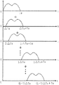
- FIG. 1 is a schematic diagram of a conventional time division multiplexing technology.
- time durations (referred to as timeslot widths in engineering) of multiplexed signal symbols are respectively T1, T2, T3, T4, . . . , and in engineering, the signal symbols usually occupy a same timeslot bandwidth.
- ⁇ T is a minimum guard timeslot, and an actual guard timeslot width should be larger.
- ⁇ T should be greater than a sum of a transition time width of a used demultiplexing gate circuit and a maximum time jitter of a system. This is a most common time division multiplexing technology. This technology is used in most existing systems such as multichannel digital broadcast systems and multichannel digital communications systems.
- a most significant feature of this technology when it is applied to digital communications is: Multiplexed signal symbols are fully isolated from each other in terms of time, without mutual interference.
- the multiplexed signal symbols are not limited, and symbol durations (timeslot widths) of signals may have different widths.
- this technology is applicable to different communications mechanisms, provided that timeslots of the multiplexed signal symbols do not overlap or cross with each other. Therefore, this technology is most widely used. However, such multiplexing has no effect in improving spectral efficiency of a system.
- a conventional idea is that adjacent channels do not overlap in time domain, to avoid interference between the adjacent channels.
- this technology limits improvement of spectral efficiency.
- An idea of a time division multiplexing technology in the prior art is that channels do not need to be isolated from each other and may strongly overlap with each other.
- overlapping between channels is considered as a new coding constraint relationship, and corresponding modulation and demodulation technologies are proposed based on the constraint relationship. Therefore, a technology is referred to as overlapped time division multiplexing (OvTDM: Overlapped Time Division Multiplexing).
- OFTDM Overlapped Time Division Multiplexing
- an overlapped time division multiplexing system includes a transmitter A 01 and a receiver A 02 .
- the transmitter A 01 includes an overlapped time division multiplexing-based modulation device 101 and a transmission device 102 .
- the overlapped time division multiplexing-based modulation device 101 is configured to generate a complex modulated envelope waveform carrying an input signal sequence.
- the transmission device 102 is configured to transmit the complex modulated envelope waveform to the receiver A 02 .
- the receiver A 02 includes a receiving device 201 and a sequence detection device 202 .
- the receiving device 201 is configured to receive the complex modulated envelope waveform transmitted by the transmission device 102 .
- the sequence detection device 202 is configured to perform data sequence detection on the received complex modulated envelope waveform in time domain, to perform decision output.
- the receiver A 02 further includes a preprocessing device 203 between the receiving device 201 and the sequence detection device 202 , configured to assist in forming a synchronously received digital signal sequence in each frame.
- the input digital signal sequence forms, by using the overlapped time division multiplexing-based modulation device 101 , transmit signals that have a plurality of symbols overlapped in time domain; and then the transmission device 102 transmits the transmit signals to the receiver A 02 .
- the receiving device 201 of the receiver A 02 receives the signals transmitted by the transmission device 102 .
- the signals form, by using the preprocessing device 203 , digital signals suitable for the sequence detection device 202 to detect and receive.
- the sequence detection device 202 performs data sequence detection on the received signals in time domain, to output a decision.
- the overlapped time division multiplexing-based modulation device 101 includes a waveform generation module 301 , a shift module 302 , a multiplication module 303 , and a superimposition module 304 .
- the waveform generation module 301 is configured to generate, based on a design parameter, an initial envelope waveform whose waveform is smooth in time domain.
- the shift module 302 is configured to shift the initial envelope waveform in time domain at a preset shift interval based on a quantity of times of overlapped multiplexing, to obtain shifted envelope waveforms at fixed intervals.
- the modulation module 305 is configured to convert an input digital signal sequence into a signal symbol sequence represented by using positive and negative symbols.
- the multiplication module 303 is configured to multiply the signal symbol sequence by offset shifted envelope waveforms at fixed intervals, to obtain modulated envelope waveforms.
- the superimposition module 304 is configured to superimpose the modulated envelope waveforms in time domain, to obtain a complex modulated envelope waveform carrying the input signal sequence.
- FIG. 5 is a block diagram of the preprocessing device 203 of the receiver A 02 .
- the preprocessing device 203 includes a synchronizer 501 , a channel estimator 502 , and a digital processor 503 .
- the synchronizer 501 implements symbol time synchronization of received signals in the receiver.
- the channel estimator 502 estimates a channel parameter.
- the digital processor 503 performs digital processing on received signals in each frame, to form a digital signal sequence suitable for the sequence detection device to perform sequence detection and receive.
- FIG. 6 is a block diagram of the sequence detection device 202 of the receiver A 02 .
- the sequence detection device 202 includes an analysis unit memory 601 , a comparator 602 , and a plurality of retained path memories 603 and Euclidean distance memories 604 or weighted Euclidean distance memories (not shown in the figure).
- the analysis unit memory 601 makes a complex convolutional coding model and a trellis diagram of the overlapped time division multiplexing system, and lists and stores all states of the overlapped time division multiplexing system;
- the comparator 602 finds, based on the trellis diagram in the analysis unit memory 601 , a path with a minimum Euclidean distance or a weighted minimum Euclidean distance to a received digital signal; and the retained path memories 603 and the Euclidean distance memories 604 or the weighted Euclidean distance memories are respectively configured to store a retained path and an Euclidean distance or a weighted Euclidean distance that are output by the comparator 602 .
- One retained path memory 603 and one Euclidean distance memory 604 or weighted Euclidean distance memory need to be prepared for each stable state.
- a length of the retained path memory 603 may be 4K-5K.
- the Euclidean distance memory 604 or the weighted Euclidean distance memory stores only a relative distance.
- a signal transmitter modulates a signal and then sends a modulated signal to a signal receiver, and the signal receiver demodulates the modulated signal after receiving it.
- a demodulation process includes a decoding step (that is, the sequence detection step performed by the foregoing sequence detection device).
- a Chase algorithm is used for decoding in most cases. The algorithm involves massive sorting operations, and a computation amount is very large.
- This application provides an overlapped multiplexing-based modulation and demodulation method and device, so as to resolve a problem in conventional decoding that a Chase algorithm is used for decoding in most cases, a process of the algorithm involves massive sorting operations, and therefore computation complexity is relatively high.
- this application provides an overlapped multiplexing-based modulation method, including:
- this application further provides an overlapped multiplexing-based demodulation method, including:
- this application further provides an overlapped multiplexing-based modulation device, including:
- an input information obtaining module configured to obtain input information
- parity check product code-based coding module configured to perform parity check product code-based coding on the input information
- an overlapped multiplexing-based modulation and coding module configured to perform overlapped multiplexing-based modulation and coding
- a signal transmission module configured to transmit a coded signal.
- a row coding unit configured to perform row coding on the information in the information bits, where specifically, the row coding unit is configured to perform row coding by assuming that information in the (k r +1) th bit of each row is a modulo-2 addition result of the first k c th columns of the current row;
- a column coding unit configured to perform column coding on the information in the information bits, where specifically, the column coding unit is configured to perform column coding by assuming that information in the (k c +1) th bit of each column is a modulo-2 addition result of the first k r th rows of the current column;
- a factor graph generation unit configured to generate a factor graph for a coding result according to a coding rule.
- the coding structure is a diagonal coding structure, a two-dimensional coding structure, a three-dimensional coding structure, or a four-dimensional coding structure.
- this application further provides an overlapped multiplexing-based demodulation device, including:
- an input signal obtaining module configured to obtain an input signal
- an overlapped multiplexing-based demodulation and decoding module configured to perform overlapped multiplexing-based demodulation and decoding on the input signal
- a factor graph-based belief propagation decoding module configured to perform factor graph-based belief propagation decoding
- a decoding result output module configured to output a decoding result.
- the factor graph-based belief propagation decoding module includes:
- an initial log-likelihood ratio calculation unit configured to calculate an initial log-likelihood ratio
- a maximum-quantity-of-iterations setting unit configured to set a maximum quantity of iterations
- a check information update unit configured to calculate a check node and update check information
- an information message update unit configured to calculate a variable node and update an information message
- a log-likelihood ratio update unit configured to calculate a log-likelihood ratio when all check nodes related to information bits provide information
- a decision unit configured to perform decision on an information sequence
- a decoding result output unit configured to output the decoding result after a specific preset condition is satisfied.
- the check information update unit is configured to calculate the check node by using a formula
- the preset condition is that the maximum quantity of iterations is reached.
- the information message update unit is configured to: calculate the variable node by using a formula
- ⁇ ji llr ⁇ ( x j ) + ⁇ i ′ ⁇ M ⁇ ( j ) ⁇ ⁇ ⁇ i ⁇ ⁇ i ′ ⁇ j , and update the information message;
- ⁇ j llr ⁇ ( x j ) + ⁇ i ′ ⁇ M ⁇ ( j ) ⁇ ⁇ i ′ ⁇ j , where
- x j is a transmit codeword in a transmit signal of a transmitter; y j is a receive codeword in the input signal received by a receiver; M(j) is a check set in which the variable node participates; M(j) ⁇ i represents a subset of the M(j) that does not include the i th check node; ⁇ i′j is the check information, and represents a log-likelihood ratio when other variable nodes except the j th variable node provide information; llr(x j ) is a representation form of a log-likelihood ratio when the receiver initially receives channel information; ⁇ ji is the information message, and represents a log-likelihood ratio when other check nodes except the i th check node provide information; and ⁇ j represents the log-likelihood ratio when all the check nodes related to the information bits provide information.
- This application provides the overlapped multiplexing-based modulation and demodulation method and device.
- a precoding structure is used, and a transmit end first performs parity check product code-based coding on an input information sequence, generates a factor graph for a coding result and according to a coding rule, then performs overlapped multiplexing-based modulation and coding, and transmits a coded signal by using an antenna.
- a signal is transmitted by using a channel, and after receiving the signal by using an antenna, a receive end first performs digital signal processing, including processes such as synchronization and equalization, then performs overlapped multiplexing-based demodulation and decoding, and finally performs factor graph-based belief propagation decoding on a decoding result, to finally obtain a decoded sequence.
- digital signal processing including processes such as synchronization and equalization
- a parity check code is used as a subcode
- a belief propagation idea of the factor graph is applied to a decoder end. Therefore, a parity check product code in a simple structure is used.
- the factor graph is used in a decoding process, thereby reducing operation complexity.
- FIG. 1 is a schematic diagram of a conventional time division multiplexing technology
- FIG. 2 is a schematic diagram of an overlapped time division multiplexing principle
- FIG. 3 is a schematic structural diagram of an overlapped time division multiplexing system
- FIG. 4 is a schematic structural diagram of an overlapped time division multiplexing-based modulation device
- FIG. 5 is a schematic structural diagram of a preprocessing device of a receiver
- FIG. 6 is a schematic structural diagram of a sequence detection device of a receiver
- FIG. 7 is a structural diagram of a parity check product code according to an embodiment of this application.
- FIG. 8 is a two-way transfer factor graph according to an embodiment of this application.
- FIG. 9 is a schematic diagram of a correspondence between a parity check product code matrix and a factor graph according to an embodiment of this application.
- FIG. 10 is a block diagram of a transmit end in a precoding OvXDM system according to an embodiment of this application.
- FIG. 11 is a schematic flowchart of an overlapped multiplexing-based modulation method according to an embodiment of this application.
- FIG. 12 is a schematic flowchart of a parity check product code-based coding step in an overlapped multiplexing-based modulation method according to an embodiment of this application;
- FIG. 13 is a schematic flowchart of a overlapped multiplexing-based modulation and coding step in an overlapped multiplexing-based modulation method according to an embodiment of this application;
- FIG. 14 is a schematic principle diagram of multiplexing of K waveforms
- FIG. 15 is a schematic principle diagram of a symbol superimposition process of K waveforms
- FIG. 16 is a schematic flowchart of an overlapped multiplexing-based demodulation method according to an embodiment of this application.
- FIG. 17 is a schematic flowchart of a decoding step in an overlapped multiplexing-based demodulation method according to an embodiment of this application;
- FIG. 19 is a node state transition diagram
- FIG. 21 is a schematic flowchart of a factor graph-based belief propagation decoding step in an overlapped multiplexing-based demodulation method according to an embodiment of this application;
- FIG. 22 is a schematic diagram of modules in an overlapped multiplexing-based modulation device according to an embodiment of this application.
- FIG. 23 is a schematic diagram of units of a parity check product code-based coding module in an overlapped multiplexing-based modulation device according to an embodiment of this application;
- FIG. 24 is a schematic diagram of modules in an overlapped multiplexing-based demodulation device according to an embodiment of this application.
- FIG. 25 is a schematic diagram of units of a factor graph-based belief propagation decoding module in an overlapped multiplexing-based demodulation device according to an embodiment of this application.
- X represents any domain, for example, time T, space S, frequency F, code C, and hybrid H.
- OvTDM overlapped time division multiplexing
- OFDM overlapped frequency division multiplexing
- a signal transmitter modulates a signal and then sends a modulated signal to a signal receiver, and the signal receiver demodulates the modulated signal after receiving it.
- a demodulation process includes a decoding step.
- a Chase algorithm is used in most cases. The algorithm involves massive sorting operations, and a computation amount is very large.
- an entire process usually ends after a receive end completes waveform decoding.
- the OvXDM system is used together with a common conventional communications technology, for example, a concatenated OvXDM system or a precoding OvXDM system, to improve overall system performance.
- a concatenated OvXDM system or a precoding OvXDM system to improve overall system performance.
- an error correction code has a relatively good error correction capability, and can improve overall system performance and reduce a bit error rate. Therefore, the error correction code is applied to the OvXDM system in most cases.
- a product code is an error correction code in a block structure.
- an idea of an iteration is introduced to a decoder end, to construct a currently popular Turbo product code.
- This is TPC-based coding.
- This type of coding is very widely used in existing communications systems.
- a Chase algorithm is used for decoding in most cases. The algorithm involves massive sorting operations, and a computation amount is very large.
- a very simple parity check code is used as a subcode, and code length control and adaptation can be performed very flexibly and conveniently.
- an iterative decoding method based on a belief propagation idea of a factor graph is used, and an operation is flexible and simple.
- the decoding idea based on belief propagation of a factor graph is introduced into a decoding method based on a parity check product code.
- Error correction codes include a product code (Turbo Product Code, TPC) and a low density parity check code (Low Density Parity Check Code, LDPC).
- TPC Tribo Product Code
- LDPC Low Density Parity Check Code
- a parity check product code is used as an example.
- a coding structure of the parity check product code is shown in FIG. 7 .
- the coding structure is very simple, and a same code length may be selected for row and column subcodes.
- a factor graph is obtained in coding relatively easily, as shown in FIG. 8 .
- Nodes shown in a lower part of the figure are variable nodes, and a quantity is a code length in a coding matrix block.
- Nodes shown in an upper part of the figure are check nodes, and a quantity is a length of a check bit.
- FIG. 9 a relationship between a corresponding coding matrix and a two-way factor graph is shown in FIG. 9 .
- the factor graph has a relatively large girth, is relatively applicable to decoding by using a belief propagation method.
- a message may be propagated by using an operation in log domain.
- an input information sequence is x
- a system processing process is: A transmit end first performs TPC-based coding on an input information sequence, then performs OvXDM-based coding, and transmits a coded signal by using an antenna.
- the signal is transmitted in a channel
- a receive end first performs digital signal processing, including processes such as synchronization and equalization; then performs OvXDM-based decoding; and finally performs TPC-based decoding on a decoding result, that is, by using a factor graph-based belief propagation decoding method in this application, to finally obtain a decoded sequence x′.
- OvXDM (X represents time T, frequency F, space S, code C, hybrid H, or the like)-based decoding includes a maximum likelihood sequence decoding algorithm such as Viterbi decoding, and a maximum posterior probability algorithm such as a BCJR algorithm, a MAP algorithm, or a Log_MAP algorithm.
- a maximum likelihood sequence decoding algorithm such as Viterbi decoding
- a maximum posterior probability algorithm such as a BCJR algorithm, a MAP algorithm, or a Log_MAP algorithm.
- N(i) a partial element information set constrained by a check node, where N(i) ⁇ j represents a subset of N(i) that does not include the j th variable node.
- M(j) a check set in which a variable node participates, where M(j) ⁇ i represents a subset of M(j) that does not include the i th check node.
- llr(x j ) a representation form of a log-likelihood ratio when channel information is initially received.
- ⁇ ji an information message, representing a log-likelihood ratio when other check nodes except the i th check node provide information.
- ⁇ j an information message, representing a log-likelihood ratio when all check nodes related to information bits provide information.
- ⁇ ij check information, representing a log-likelihood ratio when other variable nodes except the j th variable node provide information.
- this embodiment provides an overlapped multiplexing-based modulation method, including the following steps:
- Step 1 . 1 Obtain input information.
- the input information is the input digital signal sequence in FIG. 4 .
- Step 1 . 2 Perform parity check product code-based coding on the input information.
- Step 1 . 3 Perform overlapped multiplexing-based modulation and coding.
- Step 1 . 4 Transmit a coded signal, that is, transmit, to a receive end, a complex modulated envelope waveform generated in FIG. 4 as a transmit signal.
- step 1 . 2 includes the following substeps:
- Substep 1 - 1 Fill the input information into information bits in a coding structure.
- the coding structure may be a diagonal coding structure, a two-dimensional coding structure, a three-dimensional coding structure, or four-dimensional coding structure, or a higher-dimensional coding structure. This embodiment is described by using the two-dimensional coding structure as an example.
- an input information sequence is written into corresponding information bits according to a two-dimensional k c ⁇ k r structure, where k r represents a quantity of rows, and k c represents a quantity of columns.
- Substep 1 - 2 Perform row coding on the information in the information bits.
- row coding is performed by assuming that information in the (k r +1) th bit of each row is a modulo-2 addition result of the first k c th columns of the current row.
- Substep 1 - 3 Perform column coding on the information in the information bits.
- column coding is performed by assuming that information in the (k c +1) th bit of each column is a modulo-2 addition result of the first k r th rows of the current column.
- a size of matrix obtained after coding is (k c +1) ⁇ (k r +1).
- a TPC code rate thereof is
- Rate k c ⁇ k r ( k c + 1 ) ⁇ ( k r + 1 ) , and is 0.8264 in this embodiment.
- Substep 1 - 4 Generate a factor graph for a coding result according to a coding rule.
- step 1 . 3 includes the following substeps:
- Substep 2 . 1 Generate an initial envelope waveform h(t) in time domain based on a design parameter.
- a user may enter the design parameter, to implement flexible configuration in an actual system based on a system performance indicator.
- the design parameter when side lobe attenuation of the initial envelope waveform has been determined, the design parameter includes a window length L of the initial envelope waveform, for example, when the initial envelope waveform is a Bartlett envelope waveform.
- the design parameter includes a window length L and side lobe attenuation r of the initial envelope waveform, for example, when the initial envelope waveform is a Chebyshev envelope waveform.
- the design parameter may be determined based on characteristics of the corresponding initial envelope waveform.
- Substep 2 . 2 Shift the initial envelope waveform in a corresponding domain (time domain in this embodiment) based on a quantity K of times of overlapped multiplexing and a preset shift interval, to obtain shifted envelope waveforms h(t ⁇ i* ⁇ T) at fixed intervals.
- a symbol width of a signal is ⁇ T.
- ⁇ T is not less than a reciprocal of a system sampling rate.
- Substep 2 . 3 Convert a digital signal sequence obtained after coding in step 1 . 2 into a signal symbol sequence represented by using positive and negative symbols.
- 0 and 1 in the digital signal sequence are converted into +A and ⁇ A respectively, to obtain the positive-negative symbol sequence, where a value of A is any non-zero number.
- A an input ⁇ 0, 1 ⁇ bit sequence is converted into a ⁇ +1, ⁇ 1 ⁇ symbol sequence through BPSK (binary phase shift keying) modulation.
- Substep 2 . 5 Superimpose the modulated envelope waveforms x i h(t ⁇ i* ⁇ T) in the corresponding domain (time domain in this embodiment), to obtain a complex modulated envelope waveform carrying the input signal sequence, namely, a transmitted signal.
- the transmitted signal may be represented as
- the transmitting a coded signal in step 1 . 4 means: transmitting the obtained complex modulated envelope waveform as the transmit signal.
- FIG. 14 is a schematic principle diagram of multiplexing of K waveforms.
- the diagram is in a shape of a parallelogram.
- Each row represents a to-be-sent signal waveform x i h(t ⁇ i* ⁇ T) obtained after a to-be-sent symbol x i is multiplied by an envelope waveform h(t ⁇ i* ⁇ T) of a corresponding moment.
- a 0 to a k-1 represent a coefficient value of each part obtained after each window function waveform (an envelope waveform) is segmented for K times, and are specifically a coefficient related to an amplitude.
- FIG. 15 is a schematic principle diagram of a symbol superimposition process of K waveforms. In the superimposition process in FIG.
- left three numbers in the first row represent the first input symbol +1
- left three numbers in the second row represent the second input symbol +1
- left three numbers in the third row represent the third input symbol ⁇ 1
- middle three numbers in the first row represent the fourth input symbol ⁇ 1
- middle three numbers in the second row represent the fifth input symbol ⁇ 1
- middle three numbers in the third row represent the sixth input symbol +1
- right three numbers in the first row represent the seventh input symbol ⁇ 1
- right three numbers in the second row represent the eighth input symbol +1. Therefore, after three waveforms are superimposed, obtained output symbols are ⁇ +1 +2 +1 ⁇ 1 ⁇ 3 ⁇ 1 ⁇ 1 +1 ⁇ .
- superimposition may be performed based on the manner shown in FIG. 14 and FIG. 15 , to obtain output symbols.
- overlapped multiplexing-based modulation and coding may also be performed by using any feasible method in the prior art, in addition to the foregoing method.
- this embodiment correspondingly provides an overlapped multiplexing-based demodulation method.
- the overlapped multiplexing-based demodulation method includes the following steps:
- Step 3 . 1 Obtain an input signal.
- the input signal is the complex modulated envelope waveform signal transmitted in FIG. 4 .
- Step 3 . 2 Perform overlapped multiplexing-based demodulation and decoding on the input signal.
- Step 3 . 3 Perform factor graph-based belief propagation decoding.
- Step 3 . 4 Output a decoding result.
- step 3 . 2 specifically includes the following sub steps:
- FIG. 19 is a node state transition diagram.
- Viterbi decoding traversing all paths in the trellis diagram, comparing distances between a plurality of branches arriving at each state and a correct path in a state transition process in the trellis diagram, retaining only a path with a smallest distance, and obtaining an estimate of the correct path through comparison and screening, to implement decoding.
- step 3 . 2 may be performed by using the foregoing method, or may be performed in another feasible method in the prior art.
- step 3 . 3 includes the following substeps:
- Substep 3 - 1 Calculate an initial log-likelihood ratio.
- a result of a log-likelihood ratio is usually related to a modulation scheme, a decoding method of the OvXDM system (namely, the overlapped multiplexing-based demodulation and decoding method), and the like, with an ultimate objective to extract a soft value.
- Substep 3 - 2 Set a maximum quantity of iterations.
- a quantity of iterations is set to 50.
- a final decoded sequence is closer to an theoretical sequence.
- algorithm complexity also correspondingly increases.
- Substep 3 - 3 Calculate a check node and update check information.
- check nodes of each row and each column are calculated and updated based on a formula
- ⁇ ij 2 ⁇ tanh - 1 ( ⁇ j ′ ⁇ N ⁇ ( i ) ⁇ ⁇ ⁇ j ⁇ ⁇ tanh ⁇ ( ⁇ j ′ ⁇ i ⁇ / ⁇ 2 ) ) , where ⁇ is a continuous operation.
- Substep 3 - 4 Calculate a variable node and update an information message.
- information messages of each row and each column are updated based on a formula
- ⁇ ji llr ⁇ ( x j ) + ⁇ i ′ ⁇ M ⁇ ( j ) ⁇ ⁇ ⁇ i ⁇ ⁇ i ′ ⁇ j .
- Substep 3 - 5 Calculate a log-likelihood ratio when all check nodes related to information bits provide information.
- a new information message is calculated based on a formula
- ⁇ j llr ⁇ ( x j ) + ⁇ i ′ ⁇ M ⁇ ( j ) ⁇ ⁇ i ′ ⁇ j .
- Substep 3 - 6 Perform decision.
- a hard decision manner and a BPSK modulation scheme are used. It is assumed that corresponding modulation mapping herein is 1 ⁇ 1, 0 ⁇ +1, that is,
- x ⁇ j ⁇ 0 , ⁇ j ⁇ 0 1 , ⁇ j ⁇ 0 .
- Substep 3 - 7 Output the decoding result after a specific preset condition is satisfied.
- the preset condition is that the maximum quantity of iterations is reached.
- this embodiment correspondingly provides an overlapped multiplexing-based modulation device, including an input information obtaining module A 11 , a parity check product code-based coding module A 12 , an overlapped multiplexing-based modulation and coding module A 13 , and a signal transmission module A 14 .
- the input information obtaining module A 11 is configured to obtain input information.
- the parity check product code-based coding module A 12 is configured to perform parity check product code-based coding on the input information.
- the overlapped multiplexing-based modulation and coding module A 13 is configured to perform overlapped multiplexing-based modulation and coding.
- the signal transmission module A 14 is configured to transmit a coded signal.
- the parity check product code-based coding module A 12 includes an information bit filling unit A 21 , a row coding unit A 22 , a column coding unit A 23 , and a factor graph generation unit A 24 .
- the information bit filling unit A 21 is configured to fill the input information into information bits in a coding structure.
- the coding structure may be a diagonal coding structure, a two-dimensional coding structure, a three-dimensional coding structure, or four-dimensional coding structure, or a higher-dimensional coding structure. This embodiment is described by using the two-dimensional coding structure as an example.
- the row coding unit A 22 is configured to perform row coding on the information in the information bits. Specifically, the row coding unit is configured to perform row coding by assuming that information in the (k r +1) th bit of each row is a modulo-2 addition result of the first k c th columns of the current row.
- the column coding unit A 23 is configured to perform column coding on the information in the information bits. Specifically, the column coding unit is configured to perform column coding by assuming that information in the (k c +1) th bit of each column is a modulo-2 addition result of the first k r th rows of the current column.
- the factor graph generation unit A 24 is configured to generate a factor graph for a coding result according to a coding rule.
- the overlapped multiplexing-based modulation device provided in this embodiment is corresponding to the overlapped multiplexing-based modulation method provided in Embodiment 1. Therefore, a principle of the device is not described in detail herein.
- this embodiment correspondingly provides an overlapped multiplexing-based demodulation device, including an input signal obtaining module B 11 , an overlapped multiplexing-based demodulation and decoding module B 12 , a factor graph-based belief propagation decoding module B 13 , and a decoding result output module B 14 .
- the input signal obtaining module B 11 is configured to obtain an input signal.
- the overlapped multiplexing-based demodulation and decoding module B 12 is configured to perform overlapped multiplexing-based demodulation and decoding on the input signal.
- the factor graph-based belief propagation decoding module B 13 is configured to perform factor graph-based belief propagation decoding.
- the decoding result output module B 14 is configured to output a decoding result.
- the factor graph-based belief propagation decoding module B 13 includes an initial log-likelihood ratio calculation unit B 21 , a maximum-quantity-of-iterations setting unit B 22 , a check information update unit B 23 , an information message update unit B 24 , a log-likelihood ratio update unit B 25 , a decision unit B 26 , and a decoding result output unit B 27 .
- the initial log-likelihood ratio calculation unit B 21 is configured to calculate an initial log-likelihood ratio.
- the maximum-quantity-of-iterations setting unit B 22 is configured to set a maximum quantity of iterations.
- the check information update unit B 23 is configured to calculate a check node and update check information.
- the information message update unit B 24 is configured to calculate a variable node and update an information message.
- the log-likelihood ratio update unit B 25 is configured to calculate a log-likelihood ratio when all check nodes related to information bits provide information.
- the decision unit B 26 is configured to perform decision.
- the decoding result output unit B 27 is configured to output the decoding result after a specific preset condition is satisfied.
- the preset condition may be that the maximum quantity of iterations is reached.
- a hard decision manner and a BPSK modulation scheme are used. It is assumed that corresponding modulation mapping herein is 1 ⁇ 1, 0 ⁇ +1, that is,
- x ⁇ j ⁇ 0 , ⁇ j ⁇ 0 1 , ⁇ j ⁇ 0 .
- the check information update unit B 23 is configured to calculate the check node by using a formula
- the information message update unit B 24 is configured to calculate the variable node by using a formula
- ⁇ ji llr ⁇ ( x j ) + ⁇ i ′ ⁇ M ⁇ ( j ) ⁇ ⁇ ⁇ i ⁇ ⁇ i ′ ⁇ j , and update the information message.
- the log-likelihood ratio update unit B 25 is configured to calculate the log-likelihood ratio when all the check nodes related to the information bits provide information by using a formula
- ⁇ j llr ⁇ ( x j ) + ⁇ i ′ ⁇ M ⁇ ( j ) ⁇ ⁇ i ′ ⁇ j , where
- x j is a transmit codeword in a transmit signal of a transmitter; y j is a receive codeword in the input signal received by a receiver; M(j) is a check set in which the variable node participates; M(j) ⁇ i represents a subset of the M(j) that does not include the i th check node; ⁇ i′j is the check information, and represents a log-likelihood ratio when other variable nodes except the j th variable node provide information; llr(x j ) is a representation form of a log-likelihood ratio when the receiver initially receives channel information; ⁇ ji is the information message, and represents a log-likelihood ratio when other check nodes except the i th check node provide information; and ⁇ j represents the log-likelihood ratio when all the check nodes related to the information bits provide information.
- the overlapped multiplexing-based demodulation device provided in this embodiment is corresponding to the overlapped multiplexing-based demodulation method provided in Embodiment 2. Therefore, a principle of the device is not described in detail herein.
- the embodiments of this application provide the overlapped multiplexing-based modulation and demodulation method and device.
- a precoding structure is used, and a transmit end first performs parity check product code-based coding on an input information sequence, then performs overlapped multiplexing-based modulation and coding, and transmits a coded signal by using an antenna.
- a signal is transmitted by using a channel, and after receiving the signal by using an antenna, a receive end first performs digital signal processing, including processes such as synchronization and equalization, then performs overlapped multiplexing-based demodulation and decoding, and finally performs factor graph-based belief propagation decoding on a decoding result, to finally obtain a decoded sequence.
- a product code-based decoding method is used, a parity check code is used as a subcode, and a belief propagation idea of a factor graph is applied to a decoder end. Therefore, a parity check product code in a simple structure is used.
- the factor graph is used in a decoding process, thereby reducing operation complexity.
- overlapped multiplexing-based modulation and demodulation method and device may be applied to wireless communications systems such as mobile communications, satellite communications, microwave line-of-sight communications, scatter communications, atmospheric optical communications, infrared communications, and underwater acoustic communications systems; and may be applied to both large-capacity wireless transmission and small-capacity lightweight radio systems.
- the program may be stored in a computer-readable storage medium.
- the storage medium may include a read-only memory, a random access memory, a magnetic disk, an optical disk, or the like.
Landscapes
- Engineering & Computer Science (AREA)
- Computer Networks & Wireless Communication (AREA)
- Signal Processing (AREA)
- Physics & Mathematics (AREA)
- Probability & Statistics with Applications (AREA)
- Theoretical Computer Science (AREA)
- Error Detection And Correction (AREA)
Abstract
Description
and update the check information, where δij is the check information, and represents a log-likelihood ratio when other variable nodes except the jth variable node provide information; λj′i is the information message, and represents a log-likelihood ratio when other check nodes except the ith check node provide information; N(i) is a partial element information set constrained by the check node; N(i)/j represents a subset of N(i) that does not include the jth variable node; and Π is a continuous multiplication operation; and/or
and update the information message; and
where
and is 0.8264 in this embodiment.
where Π is a continuous operation.
and update the check information, where δij is the check information, and represents a log-likelihood ratio when other variable nodes except the jth variable node provide information; λj′i is the information message, and represents a log-likelihood ratio when other check nodes except the ith check node provide information; N(i) is a partial element information set constrained by the check node; N(i)\j represents a subset of N(i) that does not include the jth variable node; and Π is a continuous multiplication operation.
and update the information message.
where
Claims (7)
Applications Claiming Priority (4)
| Application Number | Priority Date | Filing Date | Title |
|---|---|---|---|
| CN201610886202.XA CN107919941B (en) | 2016-10-10 | 2016-10-10 | Modulation-demodulation method and device based on overlapping multiplexing |
| CN201610886202.X | 2016-10-10 | ||
| CN201610886202 | 2016-10-10 | ||
| PCT/CN2017/091965 WO2018068540A1 (en) | 2016-10-10 | 2017-07-06 | Overlapped multiplexing-based modulation and demodulation method and device |
Related Parent Applications (1)
| Application Number | Title | Priority Date | Filing Date |
|---|---|---|---|
| PCT/CN2017/091965 Continuation WO2018068540A1 (en) | 2016-10-10 | 2017-07-06 | Overlapped multiplexing-based modulation and demodulation method and device |
Publications (2)
| Publication Number | Publication Date |
|---|---|
| US20190238255A1 US20190238255A1 (en) | 2019-08-01 |
| US10833792B2 true US10833792B2 (en) | 2020-11-10 |
Family
ID=61891855
Family Applications (1)
| Application Number | Title | Priority Date | Filing Date |
|---|---|---|---|
| US16/379,744 Expired - Fee Related US10833792B2 (en) | 2016-10-10 | 2019-04-09 | Overlapped multiplexing-based modulation and demodulation method and device |
Country Status (6)
| Country | Link |
|---|---|
| US (1) | US10833792B2 (en) |
| EP (1) | EP3525373A4 (en) |
| JP (1) | JP2019535196A (en) |
| KR (1) | KR102212174B1 (en) |
| CN (1) | CN107919941B (en) |
| WO (1) | WO2018068540A1 (en) |
Families Citing this family (11)
| Publication number | Priority date | Publication date | Assignee | Title |
|---|---|---|---|---|
| CN107645461B (en) * | 2016-07-22 | 2021-09-24 | 广东恒域科技股份有限公司 | Modulation method and device suitable for OvXDM system and OvXDM system |
| CN107919937B (en) * | 2016-10-10 | 2020-10-27 | 深圳光启合众科技有限公司 | Decoding method, device, modulation and demodulation method and system based on overlapping multiplexing |
| JP2020535671A (en) | 2017-09-21 | 2020-12-03 | オッポ広東移動通信有限公司Guangdong Oppo Mobile Telecommunications Corp., Ltd. | Resource selection method, equipment and computer storage media |
| CN110808741A (en) * | 2019-11-19 | 2020-02-18 | 安徽新华学院 | LDPC channel coding method based on OVTDM and CS in WSN |
| CN110855297A (en) * | 2019-11-19 | 2020-02-28 | 安徽新华学院 | LDPC channel coding module and system applied to wireless sensor network |
| CN113949453B (en) * | 2020-07-15 | 2023-04-11 | 华为技术有限公司 | Modulation coding and demodulation decoding method, device, equipment and communication system |
| CN113949426A (en) * | 2020-07-16 | 2022-01-18 | 维沃移动通信有限公司 | Information sending method, receiving method and communication equipment |
| CN114301473B (en) * | 2021-12-30 | 2025-03-04 | 重庆两江卫星移动通信有限公司 | A multi-level LDPC decoding method based on CSK modulation |
| CN114615126B (en) * | 2022-03-04 | 2024-02-27 | 清华大学 | Signal demodulation methods, devices, equipment and media |
| CN115664904B (en) * | 2022-10-17 | 2024-12-27 | 贵州航天南海科技有限责任公司 | A signal processing method and device compatible with multi-order modulation and demodulation |
| CN117478254B (en) * | 2023-12-28 | 2024-05-17 | 深圳大学 | Method for improving LoRa network throughput by using partially overlapped channels |
Citations (11)
| Publication number | Priority date | Publication date | Assignee | Title |
|---|---|---|---|---|
| US20040221223A1 (en) * | 2003-04-29 | 2004-11-04 | Nam-Yul Yu | Apparatus and method for encoding a low density parity check code |
| US20070202889A1 (en) * | 2006-02-07 | 2007-08-30 | Samsung Electronics Co., Ltd. | Method for puncturing a low density parity check code |
| CN101388672A (en) | 2008-10-22 | 2009-03-18 | 山东大学 | An Improved Sphere Decoding Algorithm for Overlapping Code Multiplexing |
| CN101431393A (en) | 2007-11-05 | 2009-05-13 | 中国移动通信集团公司 | Overlapping multiplexing transmission method, base station and user terminal |
| CN101557364A (en) | 2009-05-12 | 2009-10-14 | 山东大学 | Joint-iterative channel estimation and decoding method of Turbo-OvCDM system |
| US20100077275A1 (en) * | 2006-10-18 | 2010-03-25 | Panasonic Corporation | Method and system for data transmission in a multiple input multiple output (mimo) system |
| US20120051208A1 (en) * | 2010-08-27 | 2012-03-01 | Daoben Li | Methods and systems for multiple access encoding, transmission and decoding |
| US20120159408A1 (en) * | 2010-01-13 | 2012-06-21 | Shawn Hershey | Implementation of factor graphs |
| US20160269049A1 (en) | 2015-03-12 | 2016-09-15 | Electronics And Telecommunications Research Institute | Data transmitting and receiving apparatus |
| US20170366201A1 (en) * | 2014-11-19 | 2017-12-21 | Lantiq Beteiligungs-GmbH & Co. KG | Low-density parity check decoding |
| EP3605898A1 (en) | 2017-04-27 | 2020-02-05 | Shen Zhen Kuang-chi Hezhong Technology Ltd. | Processing method, device and system for overlap multiplexing system |
Family Cites Families (6)
| Publication number | Priority date | Publication date | Assignee | Title |
|---|---|---|---|---|
| JP4898858B2 (en) * | 2009-03-02 | 2012-03-21 | パナソニック株式会社 | Encoder, decoder and encoding method |
| MY171443A (en) * | 2009-11-13 | 2019-10-15 | Panasonic Ip Corp America | Encoding method, decoding method, coder and decoder |
| CN101877591B (en) * | 2010-06-18 | 2016-08-03 | 中兴通讯股份有限公司 | A kind of method and apparatus of binary symmetric source coding |
| US8595590B1 (en) * | 2012-12-03 | 2013-11-26 | Digital PowerRadio, LLC | Systems and methods for encoding and decoding of check-irregular non-systematic IRA codes |
| CN104426553B (en) * | 2013-08-23 | 2017-07-28 | 上海数字电视国家工程研究中心有限公司 | The coding method of low-density parity check (LDPC) matrix |
| US9960790B2 (en) * | 2013-11-29 | 2018-05-01 | Kabushiki Kaisha Toshiba | Belief propagation decoding for short algebraic codes with permutations within the code space |
-
2016
- 2016-10-10 CN CN201610886202.XA patent/CN107919941B/en active Active
-
2017
- 2017-07-06 EP EP17861120.8A patent/EP3525373A4/en not_active Withdrawn
- 2017-07-06 KR KR1020197011049A patent/KR102212174B1/en not_active Expired - Fee Related
- 2017-07-06 JP JP2019517838A patent/JP2019535196A/en active Pending
- 2017-07-06 WO PCT/CN2017/091965 patent/WO2018068540A1/en not_active Ceased
-
2019
- 2019-04-09 US US16/379,744 patent/US10833792B2/en not_active Expired - Fee Related
Patent Citations (11)
| Publication number | Priority date | Publication date | Assignee | Title |
|---|---|---|---|---|
| US20040221223A1 (en) * | 2003-04-29 | 2004-11-04 | Nam-Yul Yu | Apparatus and method for encoding a low density parity check code |
| US20070202889A1 (en) * | 2006-02-07 | 2007-08-30 | Samsung Electronics Co., Ltd. | Method for puncturing a low density parity check code |
| US20100077275A1 (en) * | 2006-10-18 | 2010-03-25 | Panasonic Corporation | Method and system for data transmission in a multiple input multiple output (mimo) system |
| CN101431393A (en) | 2007-11-05 | 2009-05-13 | 中国移动通信集团公司 | Overlapping multiplexing transmission method, base station and user terminal |
| CN101388672A (en) | 2008-10-22 | 2009-03-18 | 山东大学 | An Improved Sphere Decoding Algorithm for Overlapping Code Multiplexing |
| CN101557364A (en) | 2009-05-12 | 2009-10-14 | 山东大学 | Joint-iterative channel estimation and decoding method of Turbo-OvCDM system |
| US20120159408A1 (en) * | 2010-01-13 | 2012-06-21 | Shawn Hershey | Implementation of factor graphs |
| US20120051208A1 (en) * | 2010-08-27 | 2012-03-01 | Daoben Li | Methods and systems for multiple access encoding, transmission and decoding |
| US20170366201A1 (en) * | 2014-11-19 | 2017-12-21 | Lantiq Beteiligungs-GmbH & Co. KG | Low-density parity check decoding |
| US20160269049A1 (en) | 2015-03-12 | 2016-09-15 | Electronics And Telecommunications Research Institute | Data transmitting and receiving apparatus |
| EP3605898A1 (en) | 2017-04-27 | 2020-02-05 | Shen Zhen Kuang-chi Hezhong Technology Ltd. | Processing method, device and system for overlap multiplexing system |
Non-Patent Citations (10)
| Title |
|---|
| Andres I Vila, "LDPC Decoders with Informed Dynamic Scheduling", IEE Translations on Communications, vol. 58, No. 12, Dec. 1, 2010, pp. 3470-3479, XP011340164. |
| ANDRES I. VILA CASADO ; MIGUEL GRIOT ; RICHARD D. WESEL: "LDPC Decoders with Informed Dynamic Scheduling", IEEE TRANSACTIONS ON COMMUNICATIONS., IEEE SERVICE CENTER, PISCATAWAY, NJ. USA., vol. 58, no. 12, 1 December 2010 (2010-12-01), PISCATAWAY, NJ. USA., pages 3470 - 3479, XP011340164, ISSN: 0090-6778, DOI: 10.1109/TCOMM.2010.101910.070303 |
| English Translation of International Search Report dated Sep. 28, 2017 for PCT Patent Application No. PCT/CN2017/091965 filed Jul. 6, 2017, 2 pages., dated Sep. 28, 2017. |
| European Search Report for corresponding application EP 17861120: Report dated May 20, 2020. |
| Japanese Office Action for Japanese Patent Application No. 2019-517838; dated Jun. 19, 2020. |
| JUN DENG ; BING LI ; LINTAO LIU ; RUI CHEN: "AProgrammable IP Core for LDPC Decoder Based onASIP", ASIC (ASICON), 2011 IEEE 9TH INTERNATIONAL CONFERENCE ON, IEEE, 25 October 2011 (2011-10-25), pages 764 - 767, XP032120531, ISBN: 978-1-61284-192-2, DOI: 10.1109/ASICON.2011.6157317 |
| Jun Deng et al, "A Programmable IP Core for LDPC Decoder Based on ASIP", 2011 IEE 9th International Conference, Oct. 25, 2011, pp. 764-767, XP032120531. |
| Korean Office Action for Korean Application 10-2019-7011049; dated May 29, 2020. |
| XIA ZHANG ; PEIJIAN ZHANG ; DAOBEN LI: "Overlapped Time Division Multiplexing System Using Turbo Product Code", WIRELESS COMMUNICATIONS NETWORKING AND MOBILE COMPUTING (WICOM), 2010 6TH INTERNATIONAL CONFERENCE ON, IEEE, PISCATAWAY, NJ, USA, 23 September 2010 (2010-09-23), Piscataway, NJ, USA, pages 1 - 5, XP031828063, ISBN: 978-1-4244-3708-5 |
| Xia Zhang, "Overlapped Time Division Multiplexing System Using Turbo Product Code", Wireless Communication Networking and Mobile Computing, Sep. 23, 2010, pp. 1-5, XP031828063. |
Also Published As
| Publication number | Publication date |
|---|---|
| KR20190053237A (en) | 2019-05-17 |
| WO2018068540A1 (en) | 2018-04-19 |
| CN107919941B (en) | 2022-01-25 |
| JP2019535196A (en) | 2019-12-05 |
| EP3525373A4 (en) | 2020-06-17 |
| EP3525373A1 (en) | 2019-08-14 |
| KR102212174B1 (en) | 2021-02-03 |
| CN107919941A (en) | 2018-04-17 |
| US20190238255A1 (en) | 2019-08-01 |
Similar Documents
| Publication | Publication Date | Title |
|---|---|---|
| US10833792B2 (en) | Overlapped multiplexing-based modulation and demodulation method and device | |
| US8369448B2 (en) | Bit mapping scheme for an LDPC coded 32APSK system | |
| US8352846B2 (en) | Method an apparatus for low density parity check codes encoding and decoding | |
| US11082147B2 (en) | Processing method, device and system for overlap multiplexing system | |
| Massey | Deep-space communications and coding: A marriage made in heaven | |
| Yuan et al. | Polar-coded non-coherent communication | |
| US8386904B2 (en) | High speed low density parity check codes encoding and decoding | |
| US10771303B2 (en) | Overlapped multiplexing-based decoding method and device, and modulation and demodulation method and system | |
| CN108667561A (en) | signal processing method, device and storage medium and processor | |
| Cuc et al. | Performances Comparison between Low Density Parity Check Codes and Polar Codes | |
| CN109560820A (en) | A kind of simplified method of decoding of combined channel coding and physical-layer network coding | |
| Calderbank et al. | Synchronizable codes for the optical OPPM channel | |
| Alqudah et al. | Efficient generation of puncturing-assisted rate-matched 5G new radio LDPC codes for faster-than-Nyquist signaling | |
| Geller | Advanced synchronization techniques for the Internet of Things | |
| EP3490177A1 (en) | Fast decoding method and device suitable for ovxdm system, and ovxdm system | |
| CN102148619B (en) | Self-adaptive linear programming decoding algorithm applied in LDPC (Low Density Parity Code) | |
| CN106385306B (en) | A Coding Cooperative Method Based on Rate Compatible Convolutional LDPC Codes | |
| EP1901436A2 (en) | Bit mapping scheme for an LDPC coded 16APSK system | |
| Hsu | Robust wireless communications for low power short message Internet-of-Things applications | |
| CN109302269A (en) | A method and system for obtaining approximate optimal decoding of bit error rate | |
| Khan et al. | Puncturing optimization algorithm and its applications in free space communications | |
| Kumaraswamy | Simplified detection techniques for serially concatenated coded continuous phase modulations | |
| CN117528699A (en) | Optimal relay node selection and power allocation method and system based on interruption performance | |
| CN116684042A (en) | Decoding method and system for sliding window packet scheduling based on dual spatially coupled LDPC codes | |
| KR101687243B1 (en) | Method and apparatus for providing data transmission and receiving |
Legal Events
| Date | Code | Title | Description |
|---|---|---|---|
| FEPP | Fee payment procedure |
Free format text: ENTITY STATUS SET TO UNDISCOUNTED (ORIGINAL EVENT CODE: BIG.); ENTITY STATUS OF PATENT OWNER: SMALL ENTITY |
|
| AS | Assignment |
Owner name: SHENZHEN SUPER DATA LINK TECHNOLOGY LTD., CHINA Free format text: ASSIGNMENT OF ASSIGNORS INTEREST;ASSIGNORS:LIU, RUOPENG;JI, CHUNLIN;ZHENG, HAO;AND OTHERS;SIGNING DATES FROM 20190321 TO 20190326;REEL/FRAME:048845/0272 |
|
| FEPP | Fee payment procedure |
Free format text: ENTITY STATUS SET TO SMALL (ORIGINAL EVENT CODE: SMAL); ENTITY STATUS OF PATENT OWNER: SMALL ENTITY |
|
| AS | Assignment |
Owner name: SHENZHEN SHEN ZHEN KUANG-CHI HEZHONG TECHNOLOGY LT Free format text: ASSIGNMENT OF ASSIGNORS INTEREST;ASSIGNOR:SHENZHEN SUPER DATA LINK TECHNOLOGY LTD.;REEL/FRAME:049930/0386 Effective date: 20190715 Owner name: SHENZHEN SHEN ZHEN KUANG-CHI HEZHONG TECHNOLOGY LTD, CHINA Free format text: ASSIGNMENT OF ASSIGNORS INTEREST;ASSIGNOR:SHENZHEN SUPER DATA LINK TECHNOLOGY LTD.;REEL/FRAME:049930/0386 Effective date: 20190715 |
|
| STPP | Information on status: patent application and granting procedure in general |
Free format text: NON FINAL ACTION MAILED |
|
| AS | Assignment |
Owner name: SHEN ZHEN KUANG-CHI HEZHONG TECHNOLOGY LTD, CHINA Free format text: ASSIGNMENT OF ASSIGNORS INTEREST;ASSIGNOR:SHENZHEN SUPER DATA LINK TECHNOLOGY LTD;REEL/FRAME:052880/0977 Effective date: 20200608 |
|
| STPP | Information on status: patent application and granting procedure in general |
Free format text: RESPONSE TO NON-FINAL OFFICE ACTION ENTERED AND FORWARDED TO EXAMINER |
|
| STPP | Information on status: patent application and granting procedure in general |
Free format text: NOTICE OF ALLOWANCE MAILED -- APPLICATION RECEIVED IN OFFICE OF PUBLICATIONS |
|
| STPP | Information on status: patent application and granting procedure in general |
Free format text: PUBLICATIONS -- ISSUE FEE PAYMENT VERIFIED |
|
| STCF | Information on status: patent grant |
Free format text: PATENTED CASE |
|
| LAPS | Lapse for failure to pay maintenance fees |
Free format text: PATENT EXPIRED FOR FAILURE TO PAY MAINTENANCE FEES (ORIGINAL EVENT CODE: EXP.); ENTITY STATUS OF PATENT OWNER: SMALL ENTITY |
|
| STCH | Information on status: patent discontinuation |
Free format text: PATENT EXPIRED DUE TO NONPAYMENT OF MAINTENANCE FEES UNDER 37 CFR 1.362 |
|
| FP | Lapsed due to failure to pay maintenance fee |
Effective date: 20241110 |