US10832532B2 - Automated transaction machine - Google Patents
Automated transaction machine Download PDFInfo
- Publication number
- US10832532B2 US10832532B2 US16/344,117 US201716344117A US10832532B2 US 10832532 B2 US10832532 B2 US 10832532B2 US 201716344117 A US201716344117 A US 201716344117A US 10832532 B2 US10832532 B2 US 10832532B2
- Authority
- US
- United States
- Prior art keywords
- currency
- interior
- atm
- holding portion
- shell
- Prior art date
- Legal status (The legal status is an assumption and is not a legal conclusion. Google has not performed a legal analysis and makes no representation as to the accuracy of the status listed.)
- Active
Links
Images


Classifications
-
- G—PHYSICS
- G07—CHECKING-DEVICES
- G07F—COIN-FREED OR LIKE APPARATUS
- G07F19/00—Complete banking systems; Coded card-freed arrangements adapted for dispensing or receiving monies or the like and posting such transactions to existing accounts, e.g. automatic teller machines
- G07F19/20—Automatic teller machines [ATMs]
- G07F19/205—Housing aspects of ATMs
-
- G—PHYSICS
- G06—COMPUTING OR CALCULATING; COUNTING
- G06Q—INFORMATION AND COMMUNICATION TECHNOLOGY [ICT] SPECIALLY ADAPTED FOR ADMINISTRATIVE, COMMERCIAL, FINANCIAL, MANAGERIAL OR SUPERVISORY PURPOSES; SYSTEMS OR METHODS SPECIALLY ADAPTED FOR ADMINISTRATIVE, COMMERCIAL, FINANCIAL, MANAGERIAL OR SUPERVISORY PURPOSES, NOT OTHERWISE PROVIDED FOR
- G06Q20/00—Payment architectures, schemes or protocols
- G06Q20/08—Payment architectures
- G06Q20/18—Payment architectures involving self-service terminals [SST], vending machines, kiosks or multimedia terminals
-
- G—PHYSICS
- G07—CHECKING-DEVICES
- G07D—HANDLING OF COINS OR VALUABLE PAPERS, e.g. TESTING, SORTING BY DENOMINATIONS, COUNTING, DISPENSING, CHANGING OR DEPOSITING
- G07D11/00—Devices accepting coins; Devices accepting, dispensing, sorting or counting valuable papers
- G07D11/40—Device architecture, e.g. modular construction
Definitions
- the present disclosure relates to automated transaction machines.
- ATMs Automated transactions machines, hereafter “ATMs,” are commonly used to carry out a variety of financial or commercial transactions. Most commonly, these transactions include dispensing cash, providing checking account balances, paying bills and/or receiving deposits from users. ATMs may also perform a variety of other transactions, including the sale and purchase of tickets, issuance of coupons, check or voucher presentation, the printing of script and a variety of other functions.
- An automated transaction machine can include at least one currency cassette, a currency recycler, a user interface, a transceiver, a shell, a door, a slot, and a cart.
- the at least one currency cassette can be configured to a hold a plurality of banknotes.
- the currency recycler can be configured to selectively extract one or more of the plurality of banknotes held by the at least one currency cassette.
- the user interface can be configured to receive an input from a user.
- the input can correspond to at least part of a request for currency dispensing.
- the transceiver can be configured to communicate with the user interface and can be configured to receive the input and transmit the input remotely for approval of the request for currency dispensing.
- the shell can have an interior sized to at least partially enclose the at least one currency cassette and the currency recycler.
- the door can be configured to selectively close the interior of the shell.
- the slot can be formed in the door.
- the currency recycler when positioned in the interior, can be aligned with the slot and can be configured to direct the one or more banknotes extracted from the at least one currency cassette through the slot.
- the cart can have a holding portion and a plurality of wheels.
- the holding portion can rest on the plurality of wheels.
- the shell can have an opening sized to receive the cart.
- the at least one currency cassette can be carried by the holding portion and also rests on the plurality of wheels through the holding portion when the at least one currency cassette is in the interior.
- Respective, lowermost edges of the plurality of wheels can be positioned lower than a lowermost edge of the holding portion and lower than a lowermost edge of the at least one currency cassette when the at least one currency cassette is in the interior.
- FIG. 1 is a schematic, functional block diagram of an exemplary ATM according to one or more implementations of the present disclosure
- FIG. 2 is a perspective view of an ATM according to one or more implementations of the present disclosure
- FIG. 3 is a top view of the ATM shown in FIG. 2 ;
- FIG. 4 is a front view of the ATM shown in FIG. 2 ;
- FIG. 5 is a left side view of the ATM shown in FIG. 2 ;
- FIG. 6 is another perspective view of the ATM shown in FIG. 2 ;
- FIG. 7 is another perspective view of the ATM shown in FIG. 2 ;
- FIG. 8 is a partial perspective view of the ATM shown in FIG. 2 ;
- FIG. 9 is another partial perspective view of the ATM shown in FIG. 2 ;
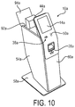
- FIG. 10 is another perspective view of the ATM of FIG. 2 , showing a currency cassette being removed;
- FIG. 11 is another perspective view of the ATM of FIG. 2 , showing components of the ATM associated with currency dispensing being removed from an external shell of the ATM;
- FIG. 12 is a perspective view of the ATM of FIG. 2 , generally from the side, showing the components of the ATM associated with currency dispensing being removed from the external shell of the ATM;
- FIG. 13 is a perspective view of an ATM according to one or more implementations of the present disclosure, showing components of the ATM associated with currency dispensing being removed from an external shell of the ATM;
- FIG. 14 is a perspective view of the ATM of FIG. 13 , generally from the side, showing the components of the ATM associated with currency dispensing being removed from the external shell of the ATM;
- FIG. 15 is another perspective view of the ATM of FIG. 13 , showing the components of the ATM associated with currency dispensing being removed from the external shell of the ATM;
- FIG. 16 is a front view of a cart according to another exemplary implementation of the present disclosure.
- FIG. 17 is a top view of the cart shown in FIG. 16 ;
- FIG. 18 is a bottom view of the cart shown in FIG. 16 ;
- FIG. 19 is a right-hand view of the cart shown in FIG. 16 ;
- FIG. 20 is a left-hand view of the cart shown in FIG. 16 ;
- FIG. 21 is a first perspective view of the cart shown in FIG. 16 ;
- FIG. 22 is a second perspective view of the cart shown in FIG. 16 ;
- FIG. 23 is a perspective view of an ATM according to an implementation of the present disclosure, the ATM incorporating the cart shown in FIG. 16 ;
- FIG. 24 is a perspective view of the ATM of FIG. 23 with the cart being removed from an interior of a shell of the ATM;
- FIG. 25 is a detail view of a portion of an interior of a shell of the ATM shown in FIG. 2 ;
- FIG. 26 is a detail view of a portion of a cart that is a portion of the ATM shown in FIG. 2 ;
- FIG. 27 is a perspective view of a cart and a composite currency unit according to another implementation of the present disclosure.
- FIG. 28 is a first perspective view of the cart shown FIG. 27 with the composite currency unit removed;
- FIG. 29 is a second perspective view of a cart of FIG. 27 ;
- FIG. 30 is a front view of a cart of FIG. 27 ;
- FIG. 31 is a front view of a cart of FIG. 27 with the composite currency unit removed;
- FIG. 32 is a bottom view of a cart of FIG. 27 ;
- FIG. 33 is a right-side view of a cart of FIG. 27 ;
- FIG. 34 is a right-side view of a cart of FIG. 27 with the composite currency unit removed;
- FIG. 35 is a top view of a cart of FIG. 27 ;
- FIG. 36 is a top view of a cart of FIG. 27 with the composite currency unit removed.
- the present disclosure can provide an ATM with an external shell and components associated with currency dispensing positioned within the shell.
- User interfaces can be positioned on a door that closes the shell.
- Currency cassettes of the ATM can be easily removable from the external shell to allow the cassettes to be stored elsewhere when the ATM is not in use. For example, the cassettes can be taken out of the shell of the ATM and stored in another room.
- components of the ATM associated with currency dispensing, other than the cassettes can be removeable and stored elsewhere during time periods when the ATM is not in use.
- an ATM may be positioned near a window inside a convenience store. Thieves have been known to drive vehicles into a store when the store is closed, at a location near the ATM, in order to take the entire ATM.
- An ATM according to one or more implementations of the present disclosure can be utilized in the exemplary operating environment to deter such actions and prevent loss. For example, the cassettes and other components of the ATM associated with currency dispensing can be removed and stored elsewhere during time periods when the store is closed and the ATM is not in use. If an aspiring thief can see that the ATM is fully or partially empty, the thief will be disincentivized from driving into the building in order to take the ATM. This is one example of a benefit provided by the present disclosure and should not be viewed as the only benefit.
- FIG. 1 discloses a functional block diagram of an exemplary ATM 10 according to one or more implementations of the present disclosure.
- the ATM 10 includes different structures and subsystems for receiving input from a user and executing transactions. Implementations of the present disclosure that are shown in detail in FIGS. 2-24 can include one or more of the components shown schematically in FIG. 1 and described below.
- the ATM 10 includes a computing device 12 .
- the exemplary computing device 12 has one or more processors and a non-transitory, computer readable medium.
- the computing device 12 operates under the control of an operating system, kernel and/or firmware and executes or otherwise relies upon various computer software applications, components, programs, objects, modules, data structures, etc.
- the exemplary computing device 12 can operate under the control of the Windows® operating system.
- the computer readable medium (memory) of the computing device 12 can include random access memory (RAM) devices comprising the main storage of computing device 12 , as well as any supplemental levels of memory, e.g., cache memories, non-volatile or backup memories (e.g., programmable or flash memories), read-only memories, etc.
- RAM random access memory
- the memory may be considered to include memory storage physically located elsewhere from RAM in the computing device 12 , such as any cache memory in a processor, as well as any storage capacity used as a virtual memory.
- the computing device 12 can also include one or more mass storage devices, e.g., a floppy or other removable disk drive, a hard disk drive, a direct access storage device (DASD), an optical drive (e.g., a CD drive, a DVD drive, etc.), and/or a tape drive, among others, represented by memory 46 .
- mass storage devices e.g., a floppy or other removable disk drive, a hard disk drive, a direct access storage device (DASD), an optical drive (e.g., a CD drive, a DVD drive, etc.), and/or a tape drive, among others, represented by memory 46 .
- mass storage devices e.g., a floppy or other removable disk drive, a hard disk drive, a direct access storage device (DASD), an optical drive (e.g
- the exemplary ATM 10 also includes a display 14 .
- the computing device 12 can control the display 14 to present information to the user for furthering completion of the transaction.
- the display 14 can be a touch screen that allows the user to enter information through the display 14 .
- the exemplary display 14 is configured to transmit any user-entered information to the computing device 12 .
- the exemplary ATM 10 also includes a key pad 16 and an encryption module 18 .
- the exemplary key pad 16 includes a plurality of keys, such as key 20 .
- the exemplary encryption module 18 has one or more processors and a non-transitory, computer readable medium. The user can press the keys of the key pad 16 to enter a Personal Identification Number (PIN).
- PIN Personal Identification Number
- the key pad 16 is placed in communication with the encryption module 18 and therefore the numbers of the PIN are received by the encryption module 18 . It is noted that the communication of the PIN is direct and secure; the PIN cannot be intercepted between the key pad 16 and the encryption module 18 .
- the PIN is then encrypted by the encryption module 18 to define a PIN block.
- the encryption module 18 includes a network encryption key and applies the network encryption key to encrypt the PIN to the PIN block.
- the exemplary encryption module 18 is configured to transmit the PIN block to the computing device 12 , which can direct the PIN block away from the ATM 10 during the completion of a financial transaction.
- the exemplary ATM 10 also includes a card reader 22 .
- the card reader 22 can receive a token from the user, such as a card.
- the card reader 22 can be configured to execute read and write operations with respect to any storage medium fixed to the user's card.
- the exemplary card reader 22 can be configured to read data from a magnetic strip on the back of a card or a chip embedded in the card.
- the exemplary card reader 22 can be configured to transmit any data read from the user's card to the computing device 12 , which can direct the data read from the card away from the ATM 10 during completion of a financial transaction.
- the exemplary card reader 22 can also be configured to receive commands and data from the computing device 12 and change data stored on the user's card.
- the exemplary ATM 10 also includes a printer module 24 .
- the computing device 12 can control the printer module 24 to print a receipt when a transaction has been completed.
- the printer module 24 can communicate one or more messages to the computing device 12 , such as a maintenance message regarding the need to refill printer paper.
- the exemplary ATM 10 also includes an article exchange unit 26 .
- the article exchange unit 26 is configured to receive items such as checks.
- An exemplary article exchange unit 26 can include a drum on which received items are stored.
- the exemplary article exchange unit 26 includes a slot 28 open to an exterior of the ATM 10 for the receipt of such items.
- an article exchange unit can be configured to facilitate the receipt of other items, different than paper.
- the article exchange unit 26 can include one or more sensors and transmit signals from any such sensors to the computing device 12 to execute an exchange.
- the computing device 12 can control the article exchange unit 26 in response to such signals.
- the article exchange unit 26 can include a sensor that detects receipt of an item such as a check.
- the article exchange unit 26 can include a further sensor in the form of a scanner that generates an image of the received item and transmits the image to the computing device 12 .
- the computing device 12 can control the article exchange unit 26 to dispense the item(s) requested by the user.
- the exemplary ATM 10 also includes a printer module 30 .
- the printer module 30 can generate a continuous record of all transactions executed by the ATM 10 .
- the computing device 12 can control the printer module 30 to supplement the record after each transaction has been completed.
- the printer module 30 can communicate one or more messages to the computing device 12 , such as a maintenance message regarding the need to refill printer paper.
- the exemplary ATM 10 also includes an access module 32 .
- the access module 32 can be positioned proximate to a rear side of the ATM 10 .
- the access module 32 can be utilized by service and support technicians.
- the access module 32 can be utilized by a field engineer to complete software updates to the computing device 12 .
- the access module 32 can also be utilized when non-software updates and maintenance is performed, such as the refilling of printer paper or currency.
- the exemplary ATM 10 also includes a transceiver 34 .
- the exemplary transceiver 34 is configured to facilitate communication between the computing device 12 and other computing devices that are distinct from and physically remote from the computing device 12 .
- An example of such a remote computing device is a server computing device, such as a banking or financial institution server communicating with a plurality of ATMs.
- the exemplary transceiver 34 places the computing device 12 in communication with one or more networks, such as network 36 .
- the network 36 can be a local area network (LAN), a wide area network (WAN) such as the Internet, a Multi-protocol label switching (MPLS) network, a cellular network such as operated by cellular phone companies, or any combination thereof.
- LAN local area network
- WAN wide area network
- MPLS Multi-protocol label switching
- cellular network such as operated by cellular phone companies, or any combination thereof.
- the network 36 can be a financial/bank network such as NYCE, PULSE, PLUS, Cirrus, AFFN, Interac, Interswitch, STAR, LINK, MegaLink, or BancNet.
- the transceiver 34 can transmit data and requests for input generated by the computing device 12 and receive responses to these requests, directing these responses to the computing device 12 .
- the exemplary ATM 10 also includes a transceiver 38 .
- the exemplary transceiver 38 is configured to facilitate communication between at least one of the encryption module 18 and the computing device 12 and other computing devices that are distinct from and physically proximate to the ATM 10 .
- An example of such a proximate computing device is a smartphone possessed by the user.
- the dashed connection lines in FIG. 1 represent optional interconnections.
- the exemplary transceiver 38 can place the user's smartphone in communication with the encryption module 18 , the computing device 12 , or both.
- the exemplary transceiver 38 can implement various communication protocols.
- the transceiver 38 can be a Near Field Communication (NFC) device.
- the transceiver 38 can be a Bluetooth beacon.
- the transceiver 38 can transmit and receive data and requests for input generated by the encryption module 18 and/or the computing device 12 , such transmissions occurring with the user's smart phone for example.
- NFC Near Field Communication
- the exemplary ATM 10 also includes a currency recycler or advanced function dispenser (AFD) 40 .
- the AFD 40 can dispense banknotes, such as currency, and also receive banknotes.
- the exemplary AFD 40 is positioned in a safe 42 .
- One or more cassettes or cash boxes 44 are also positioned and protected in the safe 42 .
- Banknotes are stored in the cassettes 44 for disbursement to a user of the ATM 10 .
- the exemplary AFD 40 can extract the banknotes from one or more of the cassettes 44 and direct them out of the ATM 10 through the slot 28 .
- the AFD 40 thus communicates with the slot 28 in parallel with the article exchange unit 26 .
- the exemplary AFD 40 can communicate with and be controlled by the computing device 12 for at least some operations.
- Each of the cassettes 44 can engage the AFD 40 through a rack whereby the positioning of the cassettes is controlled. Further, the each of the cassettes 44 and the AFD 40 can include mating connectors of any form, whereby a positive interconnection is confirmed electronically. When one or more of the cassettes 44 and the AFD 40 are not properly interconnected, a signal or lack thereof can be communicated to the computing device 12 whereby an error message is generated or the ATM 10 can be disabled.
- the exemplary ATM 10 also includes a scanner 48 .
- the scanner 48 can scan, for example, at least a portion of a display of a smart phone and communicate the scanned display to the computing device 12 .
- a token can be displayed on the display of the smart phone and thus scanned by the scanner 48 .
- the token can be a bar code, a quick response (QR) code, a number, a string of alphanumeric characters, a weblink, or some other symbolic indicia.
- QR quick response
- the exemplary scanner 48 is configured to transmit any scanned data to the computing device 12 , which can direct the scanned away from the ATM 10 during completion of a financial transaction.
- an exemplary ATM 10 a includes at least one currency cassette configured to a hold a plurality of banknotes and a currency recycler configured to selectively extract one or more of the plurality of banknotes held by the at least one currency cassette.
- the cassette 44 and dispenser 40 described above and illustrated schematically in FIG. 1 can be utilized in the ATM 10 a .
- a structure containing both of the at least one currency cassette and the currency recycler is referenced at 52 a and is designated a composite currency unit.
- the exemplary ATM 10 a includes a plurality of user interfaces.
- a user interface in the form of a display 14 a is a touch screen display that can display information to a user and receive data from the user.
- a user interface in the form of a transceiver 38 a can communicate with a computing device of a user, such as a smartphone.
- the communication protocol between the transceiver 38 a and the smartphone can be NFC or Bluetooth.
- a user interface in the form of a biometric sensor 50 a can detect the fingerprint of a user.
- the input that is received from the user with one or all of the user interfaces 14 a , 38 a , 50 a can correspond to a request for currency dispensing.
- the user can enter a personal identification number (PIN), a desired amount of currency, and/or data associated with a pre-staged transaction through the display 14 a or with a smartphone through the transceiver 38 a .
- PIN personal identification number
- the user can place his/her finger on the biometric sensor 50 a for the ATM 10 a to search for and access a pre-staged transaction based on the fingerprint data or to confirm the user's identity before currency is dispensed.
- Other implementations of the present disclosure can incorporate user interfaces having other forms, such as by way of example and not limitation, a key pad.
- the exemplary ATM 10 a includes a second transceiver communicating with the user interface, such as transceiver 34 illustrated schematically in FIG. 1 .
- This second transceiver of the ATM 10 a is internal relative to the structure shown in FIGS. 2-12 and therefore not visible.
- the second transceiver can be configured to receive the input received by a user interface, such as any of the exemplary user interfaces set forth above.
- the communication of the input to the second transceiver can be direct from the user interface or indirect, such as through the computing device 12 illustrated in FIG. 1 .
- the second transceiver is configured to transmit the input remotely, such as to a bank server or a switch on the ATM network, for approval of the request for currency dispensing.
- the exemplary ATM 10 a includes a shell 54 a having an interior 56 a sized to at least partially enclose the at least one currency cassette and the currency recycler, referenced by the composite currency unit 52 a .
- the exemplary shell 54 a partially encloses the composite currency unit 52 a on five sides: top, bottom, left, right, and rear.
- the exemplary shell 54 a is mounted on a plate 58 a .
- a shell could enclose four sides, such as if the plate formed the bottom side of the interior 56 a .
- the exemplary shell 54 a can be formed from sheet metal or plastic and can be relatively thin and light-weight.
- the exemplary ATM 10 a includes a door 60 a configured to selectively close the interior 56 a of the shell 54 a .
- the door 60 a is arranged to be moveable between a first position and a second position. In the first position, the door 60 a closes an opening 62 a in the shell 54 a to the interior 56 a .
- the exemplary door 60 a thus closes a sixth side of the shell 54 a , the front side, when in the first position.
- the door 60 a is shown in FIGS. 2-10 in the first position. In the second position, the door 60 a is spaced from the first position and the opening 62 a in the shell 54 a to the interior 56 a is unblocked.
- the door 60 a is shown in FIGS. 11 and 12 in an exemplary second position. Alternative second positions could be defined when the door 60 a is more remote from the shell 54 a than shown in FIGS. 11 and 12 .
- the opening 62 a to the interior 56 a and the user interfaces 14 a , 38 a , 50 a are on the same side of the shell 54 a when the opening 62 a is closed by the door 60 a , the front side.
- a lock can be arranged to selectively lock the door 60 a in the first position.
- the exemplary ATM 10 a includes a slot 28 a formed in the door 60 a .
- the currency recycler when positioned in the interior 56 a , is aligned with the slot 28 a and is configured to direct banknotes that have been extracted from the currency cassette through the slot 28 a .
- the exit port of the composite currency unit 52 a is referenced at 64 a.
- the exemplary ATM 10 a includes a cart 66 a .
- the cart 66 a has a holding portion 68 a and a plurality of wheels, such as wheels 70 a and 72 a .
- the exemplary cart 66 a includes two other wheels opposite to the wheels 70 a , 72 a , on an opposite side of the holding portion 68 a .
- the holding portion 68 a rests on the plurality of wheels 70 a , 72 a and the wheels that are not visible in the Figures.
- the exemplary holding portion 68 a is supported by the plurality of wheels 70 a , 72 a and the wheels that are not visible in the Figures.
- the exemplary holding portion 68 a is carried by the plurality of wheels 70 a , 72 a and the wheels that are not visible in the Figures.
- the weight of the exemplary holding portion 68 a is transmitted to the plurality of wheels 70 a , 72 a and the wheels that are not visible in the Figures, to a bottom portion of the shell 54 a and not sides of the shell 54 a , and then to the plate 58 a.
- the opening 62 a of the exemplary shell 54 a is sized to receive the cart 66 a .
- the exemplary cart 66 a is moveable fully in and fully out of the interior 56 a of the shell 54 a while the at least one currency cassette and the currency recycler (combined in the exemplary composite currency unit 52 a ) are carried by the holding portion 68 a and resting on the plurality of wheels 70 a , 72 a and the wheels that are not visible in the Figures.
- the currency cassette is carried by the holding portion 68 a and also rests on the plurality of wheels 70 a , 72 a and the wheels that are not visible in the Figures, through the holding portion 68 a , when the currency cassette is in the interior 56 a.
- the exemplary cart 66 a and exemplary shell 54 a are thus selectively engagable with one another.
- the exemplary cart 66 a can be wheeled into the exemplary shell 54 a , the door 60 a shut (the first position), and the ATM 10 can then be used to dispense currency.
- the door 60 a can be opened, the exemplary cart 66 a can be wheeled out of the shell 54 a and be unconnected with the shell 54 a without damage to the exemplary cart 66 a or the exemplary shell 54 a , and then reengaged again to accomplish currency dispensing.
- either the exemplary cart 66 a or the exemplary shell 54 a can be replaced with a newer version and engage the remaining component.
- Respective lowermost edges of the plurality of wheels 70 a , 72 a and the wheels that are not visible in the Figures contact a plane referenced at 78 a , referenced in FIG. 5 .
- a lowermost edge of the holding portion 68 a is in a plane referenced at 80 a .
- a lowermost edge of the at least one currency cassette is no lower than a lowermost edge of the composite currency unit 52 a , which is in a plane referenced at 82 a .
- the lowermost edges of the plurality of wheels 70 a , 72 a and the wheels that are not visible in the Figures are positioned lower than the lowermost edge of the holding portion 68 a because the plane 78 a is lower than the plane 80 a .
- the lowermost edges of the plurality of wheels 70 a , 72 a and the wheels that are not visible in the Figures are positioned lower than the lowermost edge of the currency cassette when the at least one currency cassette is in the interior because the plane 78 a is lower than the plane 82 a .
- a weight of the at least one currency cassette is not transmitted to sides of the shell 54 a in the exemplary ATM 10 a , but to a bottom or floor portion of the shell 54 a through the wheels 70 a , 72 a and the wheels that are not visible in the Figures.
- the currency recycler as part of the composite current unit 52 a , is also carried by the holding portion 68 a and also rests on the plurality of wheels 70 a , 72 a and the wheels that are not visible in the Figures, through the holding portion 68 a , when the currency recycler is in the interior 56 a .
- a lowermost edge of the currency recycler is no lower than the lowermost edge of the composite currency unit 52 a , which is in the plane 82 a . Therefore, the respective lowermost edges of the plurality of wheels 70 a , 72 a and the wheels that are not visible in the Figures are positioned lower than a lowermost edge of the currency recycler when the currency recycler is in the interior 56 a.
- the exemplary user interfaces 14 a , 38 a , and 50 a are mounted on the door 60 a and the door 60 a is mounted on the composite currency unit 52 a .
- the exemplary user interfaces 14 a , 38 a , and 50 a are carried by the holding portion 68 a and also rest on the plurality of wheels 70 a , 72 a and the wheels that are not visible in the Figures, through the holding portion 68 a , when the currency recycler is in the interior 56 a as well as when the currency recycler is not in the interior 56 a .
- the respective lowermost edges of the plurality of wheels 70 a , 72 a and the wheels that are not visible in the Figures (in plane 78 a ) are positioned lower than a lowermost edge of the user interfaces 14 a , 38 a , and 50 a , as shown by a comparison between FIGS. 4 and 5 .
- the exemplary ATM 10 a also includes a guide track 84 a positioned in the interior 56 a .
- the exemplary ATM 10 a also includes a rail 86 a engaged, directly or indirectly, with the cart 66 a .
- the exemplary rail 86 a extends along a longitudinal axis 88 a that is parallel to or colinear with an axis 90 a of movement of the cart 66 a in and out of the interior 56 a .
- the exemplary rail 86 a and the exemplary guide track 84 a are engageable with one another upon movement of the cart 66 a into the interior 56 a .
- the rail 86 a and the guide track 84 a can engage one another in a tongue and groove, or spline type arrangement.
- the exemplary cart 66 a thus engages the guide track 84 a during movement into the interior 56 a.
- the exemplary ATM 10 a also includes a second opening 92 a in the shell 54 a to the interior 56 a .
- the exemplary ATM 10 a also includes a hatch 94 a mounted on the shell 54 a .
- the exemplary hatch 94 a is spaced from the door 60 a .
- the exemplary hatch 94 a is moveable between a first position closing the second opening 92 a and second position spaced from the first position.
- the currency cassette 44 a is accessible through the second opening 92 a when the hatch 94 a is away from the first position.
- the exemplary ATM 10 a also includes a first electrical coupling 96 a and a second electrical coupling 98 a .
- the exemplary first electrical coupling 96 a is mounted to the shell 54 a .
- the first electrical coupling 96 a can be male or female coupling, can include both male prongs and female sockets, and/or can include flat contacts.
- the exemplary second electrical coupling 98 a is mounted in the holding portion 68 a .
- the second electrical coupling 98 a can be male or female coupling, can include both male prongs and female sockets, and/or can include flat contacts.
- the first electrical coupling 96 a and the second electrical coupling 98 a come into engagement with one another when the cart 66 a is rolled into the interior 56 a .
- electrical data and/or power signals can be communicated through the couplings 96 a , 98 a .
- Such signals can be directed to any components positioned within the composite currency unit 52 a .
- Similar couplings can be utilized between the holding portion 48 a and the composite currency unit 52 a so that when the composite currency unit 52 a is lowered onto the holding portion 48 a the electrical connection is completed.
- an exemplary ATM 10 b includes at least one currency cassette configured to a hold a plurality of banknotes and a currency recycler configured to selectively extract one or more of the plurality of banknotes held by the at least one currency cassette, such as the cassette 44 and dispenser 40 illustrated schematically in FIG. 1 .
- a structure containing both of the at least one currency cassette and the currency recycler is referenced at 52 b in the form of a composite currency unit.
- the exemplary ATM 10 b includes a plurality of user interfaces.
- a user interface in the form of a display 14 b is a touch screen display that can display information to a user and receive data from the user.
- a user interface in the form of a transceiver 38 b can communicate with a computing device of a user, such as a smartphone.
- the communication protocol can be NFC or Bluetooth.
- a user interface in the form of a biometric sensor 50 b can detect the fingerprint of a user.
- the input from the user can correspond to a request for currency dispensing. For example, the user can enter a personal identification number (PIN), a desired amount of currency, or data associated with a pre-staged transaction through the display 14 b or with a smartphone through the transceiver 38 b .
- PIN personal identification number
- the user can place his/her finger on the biometric sensor 50 b for the ATM 10 b to access a pre-staged transaction or confirm identity.
- Other implementations of the present disclosure can incorporate user interfaces having other forms, such as by way of example and not limitation, a key pad.
- the exemplary ATM 10 b includes a second transceiver communicating with the user interface, such as second transceiver 34 illustrated schematically in FIG. 1 .
- the second transceiver of the ATM 10 b is internal relative to the structure shown in FIGS. 13-15 and therefore not visible.
- the second transceiver can be configured to receive the input received by the user interface, any of the exemplary user interfaces set forth above.
- the second transceiver is configured to transmit the input remotely for approval of the request for currency dispensing.
- the exemplary ATM 10 b includes a shell 54 b having an interior 56 b sized to at least partially enclose the at least one currency cassette and the currency recycler, referenced by the composite currency unit 52 b .
- the exemplary shell 54 b partially encloses the composite currency unit 52 b on five sides: top, bottom, left, right, and rear.
- the exemplary shell 54 b is mounted on a plate 58 b . In one or more other implementations of the present disclosure, a shell could enclose four sides.
- the exemplary shell 54 b can be formed from sheet metal or plastic and can be relatively thin and light-weight.
- the exemplary ATM 10 b includes a door 60 b configured to selectively close the interior 56 b of the shell 54 b .
- the door 60 b is arranged to be moveable between a first position and a second position. In the first position, the door 60 b closes an opening 62 b in the shell 54 b to the interior 56 b .
- the exemplary door 60 b closes a sixth side of the shell 54 b when in the first position. In the second position, the door 60 b is spaced from the first position and the opening 62 b in the shell 54 b to the interior 56 b is unblocked.
- the door 60 b is shown in FIGS. 13-15 in an exemplary second position.
- the opening 62 b to the interior 56 b and the user interfaces 14 a , 38 a , 50 a are on the same side of the shell 54 b when the opening 62 b is closed by the door 60 b , the front side.
- a lock can be arranged to selectively lock the door 60 b in the first position.
- the door 60 b is mounted on the shell 54 b for pivoting movement between the first and second positions.
- the exemplary user interfaces 14 b , 38 b , 50 b are mounted on the door 60 b.
- the exemplary ATM 10 b includes a slot 28 b formed in the door 60 b .
- the currency recycler when positioned in the interior 56 b , is aligned with the slot 28 b and is configured to direct banknotes that have been extracted from the currency cassette through the slot 28 b .
- the exit port of the composite currency unit 52 b is referenced at 64 b.
- the exemplary ATM 10 b includes a cart 66 b .
- the cart 66 b has a holding portion 68 b and a plurality of wheels, such as wheels 70 b , 74 b .
- the exemplary cart 66 b includes two other wheels opposite to the wheels 70 b , 74 b , on an opposite side of the holding portion 68 b .
- the holding portion 68 b rests on the plurality of wheels 70 b , 74 b and the wheels that are not shown.
- the exemplary holding portion 68 b is supported by the plurality of wheels 70 b , 74 b and the wheels that are not shown.
- the exemplary holding portion 68 b is carried by the plurality of wheels 70 b , 74 b and the wheels that are not shown.
- the weight of the exemplary holding portion 68 b is transmitted to the plurality of wheels 70 b , 74 b and the wheels that are not shown.
- the opening 62 b in the exemplary shell 54 b is sized to receive the cart 66 b .
- the exemplary cart 66 b is moveable fully in and fully out of the interior 56 b of the shell 54 b while the at least one currency cassette and the currency recycler (combined in the exemplary composite currency unit 52 b ) are carried by the holding portion 68 b and are resting on the plurality of wheels 70 b , 74 b and the wheels that are not shown.
- the currency cassette is carried by the holding portion 68 b and also rests on the plurality of wheels 70 b , 74 b and the wheels that are not shown, through the holding portion 68 b , when the currency cassette is in the interior 56 b.
- the exemplary cart 66 b and exemplary shell 54 b are thus selectively engagable with one another.
- the exemplary cart 66 b can be wheeled into the exemplary shell 54 b , the door 60 b shut (the first position), and the ATM 10 b can be used to dispense currency.
- the exemplary cart 66 b can be wheeled out of the shell 54 b and be unconnected with the shell 54 b without damage to the exemplary cart 66 b or the exemplary shell 54 b and reengaged again to accomplish currency dispensing.
- either the exemplary cart 66 b or the exemplary shell 54 b can be replaced with a newer version and engage the remaining component.
- the exemplary cart 66 b includes a handle 100 b configured to be grasped and held by hand, to be used to pull the cart 66 b out of the shell 54 b .
- the exemplary handle 100 b is positioned closer to the door 60 b than the at least one currency cassette 44 b , which is shown in phantom in FIG. 15 .
- the exemplary handle 100 b is positioned vertically between the slot 28 b and the user interface 14 b when the cart 66 b is positioned in the interior 56 b . This allows the handle 100 b to be easily grasped when needed.
- Respective lowermost edges of the plurality of wheels 70 b , 74 b and the wheels not visible in the Figures contact a plane such as the plane 78 a shown in FIG. 5 .
- a lowermost edge of the holding portion 68 b is in a plane such as the plane 80 a shown in FIG. 5 .
- a lowermost edge of the at least one currency cassette is no lower than a lowermost edge of the composite currency unit 52 b , which is in a plane such as the plane 82 a shown in FIG. 5 .
- the relative positions of planes for the ATM 10 b are the same as the ATM 10 a , so FIG. 5 is applicable to the ATM 10 b .
- the lowermost edges of the plurality of wheels 70 b , 74 b and the wheels not visible in the Figures are positioned lower than the lowermost edge of the holding portion 68 b because the plane 78 a is lower than the plane 80 a .
- the lowermost edges of the plurality of wheels 70 b , 74 b and the wheels not visible in the Figures are positioned lower than the lowermost edge of the currency cassette when the at least one currency cassette is in the interior because the plane 78 a is lower than the plane 82 a .
- a weight of the at least one currency cassette is not transmitted to any side of the shell 54 b.
- the currency recycler as part of the composite current unit 52 b , is also carried by the holding portion 68 b and also rests on the plurality of wheels 70 b , 74 b and the wheels not visible in the Figures, through the holding portion 68 b , when the currency recycler is in the interior 56 b .
- a lowermost edge of the currency recycler is no lower than the lowermost edge of the composite currency unit 52 b , which is in the plane 82 b . Therefore, the respective lowermost edges of the plurality of wheels 70 b , 74 b and the wheels not visible in the Figures are positioned lower than a lowermost edge of the currency recycler when the currency recycler is in the interior 56 b.
- the exemplary ATM 10 b also includes a first electrical coupling 96 b and a second electrical coupling 98 b .
- the exemplary first electrical coupling 96 b is mounted to the door 60 b .
- the first electrical coupling 96 b can include flat contacts.
- the exemplary second electrical coupling 98 b is mounted to the currency cassette 44 b , through the composite currency unit 52 b .
- the second electrical coupling 98 b can include flat contacts.
- the first electrical coupling 96 b and the second electrical coupling 98 b come into contact and electrical engagement with one another when the cart 66 b is in the interior 56 b and the door 60 b has been moved to the first position (the closed position). Electrical data and/or power signals can be communicated through the couplings 96 b , 98 b . Such signals can be directed to any component positioned within the composite currency unit 52 b.
- an exemplary ATM 10 c includes at least one currency cassette configured to a hold a plurality of banknotes and a currency recycler configured to selectively extract one or more of the plurality of banknotes held by the at least one currency cassette, such as the cassette 44 and dispenser 40 illustrated schematically in FIG. 1 .
- a structure containing both of the at least one currency cassette and the currency recycler is referenced at 52 c in the form of a composite currency unit.
- the exemplary ATM 10 c includes a plurality of user interfaces.
- a user interface in the form of a display 14 c is a touch screen display that can display information to a user and receive data from the user.
- a user interface in the form of a keypad 102 c can allow a user to enter in a PIN.
- a user interface in the form of a card reader 104 c receive a card from a user and read data on the card (from a chip or from a strip).
- the input from the user can correspond to a request for currency dispensing.
- the user can enter a personal identification number (PIN), a desired amount of currency, or data associated with a pre-staged transaction.
- PIN personal identification number
- Other implementations of the present disclosure can incorporate user interfaces having other forms.
- the exemplary ATM 10 c includes a second transceiver communicating with the user interface, such as second transceiver 34 illustrated schematically in FIG. 1 .
- the second transceiver of the ATM 10 c is internal relative to the structure shown in FIGS. 23 and 24 and therefore not visible.
- the second transceiver can be configured to receive the input received by the user interface, any of the exemplary user interfaces set forth above.
- the second transceiver is configured to transmit the input remotely for approval of the request for currency dispensing.
- the exemplary ATM 10 c includes a shell 54 c having an interior 56 c sized to at least partially enclose the at least one currency cassette and the currency recycler, referenced by the composite currency unit 52 c .
- the exemplary shell 54 c partially encloses the composite currency unit 52 c on five sides: top, bottom, left, right, and rear.
- the exemplary ATM 10 c includes a door 60 c configured to selectively close the interior 56 c of the shell 54 c .
- the door 60 c is arranged to be moveable between a first position and a second position.
- the door 60 c is mounted on the shell 54 c for pivoting movement.
- the door 60 c closes an opening 62 c in the shell 54 c to the interior 56 c .
- the exemplary door 60 c closes a sixth side, the front side, of the shell 54 c when in the first position.
- the door 60 c is shown in FIG. 23 in the first position.
- the door 60 c In the second position, the door 60 c is spaced from the first position and the opening 62 c of the shell 54 c to the interior 56 c is unblocked.
- the door 60 c is shown in FIG. 24 in an exemplary second position.
- the opening 62 c to the interior 56 c and the user interfaces 14 c , 102 c , 104 c are on the same side of the shell 54 c when the opening 62 c is closed by the door 60 c .
- the exemplary user interfaces 102 c and 104 c are mounted on the door 60 c and the user interface 14 c is mounted on the shell 54 c .
- a lock can be arranged to selectively lock the door 60 c in the first position.
- the exemplary ATM 10 c includes a slot 28 c formed in the door 60 c .
- the currency recycler when positioned in the interior 56 c , is aligned with the slot 28 c and is configured to direct banknotes that have been extracted from the currency cassette through the slot 28 c .
- the exit port of the composite currency unit 52 c is referenced at 64 c.
- the exemplary ATM 10 c includes a cart 66 c .
- the exemplary cart 66 c includes a handle 100 c configured to be grasped and held by hand and positioned closer to the door 60 c than the at least one currency cassette.
- the exemplary cart 66 c also has a holding portion 68 c and a plurality of wheels 70 c , 72 c , 74 c , 76 c .
- the holding portion 68 c rests on the plurality of wheels 70 c , 72 c , 74 c , 76 c .
- the exemplary holding portion 68 c is supported by the plurality of wheels 70 c , 72 c , 74 c , 76 c .
- the exemplary holding portion 68 c is carried by the plurality of wheels 70 c , 72 c , 74 c , 76 c .
- the weight of the exemplary holding portion 68 c is transmitted to the plurality of wheels 70 c , 72 c , 74 c , 76 c.
- the opening 62 c in the exemplary shell 54 c is sized to receive the cart 66 c .
- the exemplary cart 66 c is further defined as moveable fully in and fully out of the interior 56 c of the shell 54 c while the at least one currency cassette and the currency recycler (combined in the exemplary composite currency unit 52 c ) are carried by the holding portion 68 c and resting on the plurality of wheels 70 c , 72 c , 74 c , 76 c .
- the currency cassette as part of the composite currency unit 52 c is carried by the holding portion 68 c and thus rests on the plurality of wheels 70 c , 72 c , 74 c , 76 c through the holding portion 68 c when the currency cassette is in the interior 56 c.
- the exemplary cart 66 c and exemplary shell 54 c are thus selectively engagable with one another.
- the exemplary cart 66 c can be wheeled into the exemplary shell 54 c , the door 60 c shut (the first position), and the ATM 10 can be used to dispense currency.
- the exemplary cart 66 c can be wheeled out of the shell 54 c and be unconnected with the shell 54 c when the door 60 c is opened, without damage to the exemplary cart 66 c or the exemplary shell 54 c and reengaged again to accomplish currency dispensing.
- either the exemplary cart 66 c or the exemplary shell 54 c can be replaced with a newer version and engage the remaining component.
- Respective lowermost edges of the plurality of wheels 70 c , 72 c , 74 c , 76 c contact a plane referenced at 78 c .
- a lowermost edge of the holding portion 68 c is in a plane referenced at 80 c .
- a lowermost edge of the at least one currency cassette is no lower than a lowermost edge of the composite currency unit 52 c , which is in a plane referenced at 82 c .
- the lowermost edges of the plurality of wheels 70 c , 72 c , 74 c , 76 c are positioned lower than the lowermost edge of the holding portion 68 c because the plane 78 c is lower than the plane 80 c .
- the lowermost edges of the plurality of wheels 70 c , 72 c , 74 c , 76 c are positioned lower than the lowermost edge of the currency cassette when the at least one currency cassette is in the interior of the composite currency unit 52 c because the plane 78 c is lower than the plane 82 c .
- a weight of the at least one currency cassette is not transmitted to a side of the shell 54 c.
- the currency recycler as part of the composite current unit 52 c , is also carried by the holding portion 68 c and also rests on the plurality of wheels 70 c , 72 c , 74 c , 76 c through the holding portion 68 c when the currency recycler is in the interior 56 c .
- a lowermost edge of the currency recycler is no lower than the lowermost edge of the composite currency unit 52 c , which is in the plane 82 c . Therefore, the respective lowermost edges of the plurality of wheels 70 c , 72 c , 74 c , 76 c positioned lower than a lowermost edge of the currency recycler when the currency recycler is in the interior 56 c.
- the exemplary ATM 10 c can also include first and second electrical couplings to deliver power and communicate data to the composite currency unit 52 c .
- the first electrical coupling of the ATM 10 c can be mounted to the shell 54 c as in the ATM 10 a or to the door as in the ATM 10 b .
- the second electrical coupling can be mounted to the currency cassette, the currency recycler or a composite currency unit, as done in the ATM 10 b .
- the second electrical coupling can be mounted to the holding portion 68 c , as done in the ATM 10 a.
- the exemplary ATM 10 c includes guide tracks 84 c , 85 c positioned in the interior 56 c .
- the cart 66 c engages the guide tracks 84 , 85 c during movement into the interior 56 c .
- the wheels 70 c and 72 c engage the guide track 84 c during movement within the interior 56 c .
- the wheels 74 c and 76 c engage the guide track 85 c during movement within the interior 56 c .
- the guide tracks 84 c , 85 c face upwardly and limit movement of the wheels 70 c , 72 , 74 c , 76 c so that the cart 66 c is guided into a desired position.
- guide tracks 84 c , 85 c and the wheels 70 c , 72 c , 74 c , 76 c can ensure that mating electrical, mechanical, and electro-mechanical couplings are aligned and couple when the cart 66 c is moved into the interior 56 c.
- the exemplary cart 66 c further comprises a depression 106 c or cavity, inside the holding portion 68 c , that receives the composite currency unit 52 c .
- the exemplary depression 106 c is not symmetrical across two or more planes that extend through the depression 106 c .
- the exemplary depression 106 c is symmetrical across a single plane that extends through the depression. This plane is referenced at 108 c in FIG. 17 .
- the half of the void defined by the depression 106 c above the plane 108 c in FIG. 17 is symmetrical to or mirrored relative to the half of the void defined by the depression 106 c below the plane 108 c . It is noted that “above” and “below” are used because of the orientation of FIG.
- these void halves would be viewed as being on alternative sides of the plane 108 c , such as the void half on the left side of the plane 108 c and the void half on the right side of the plane 108 c .
- the exemplary depression 106 c is not symmetrical across two or more planes that extend through the depression 106 c so that the composite currency unit 52 c can be received in the cart 66 c in only one spatial orientation.
- only the cash cassette(s) can be carried by a cart such as the carts 66 a , 66 b , 66 c .
- a cart such as the carts 66 a , 66 b , 66 c .
- portions of the cassette(s) would be aligned with mating electrical, mechanical, and electro-mechanical couplings.
- a banknote exit port through which banknotes pass would be aligned with an intake port of the currency recycler.
- any electrical coupling(s) on the cassette for power and data would align with corresponding coupling(s) to a power bus, the computing device of the ATM, the currency recycler, and/or other components of the ATM.
- Implementations of the present disclosure can include security protocols to prevent the removal of banknotes from the currency cassette when the cart is removed from the shell.
- the cassette can include a lock that requires, to unlock, data communication between the cassette and the computing device of the ATM, the currency recycler, and/or other components of the ATM.
- the cassette can also include an alarm that is battery-powered and activated if the cassette is opened and the cassette is not in data communication between the cassette and the computing device of the ATM, the currency recycler, and/or other components of the ATM.
- a cart 66 d can be applied in one or more implementations of the present disclosure.
- the exemplary cart 66 d has a holding portion 68 d to receive a composite currency unit 52 d , which includes at least one currency cassette configured to a hold a plurality of banknotes and a currency recycler configured to selectively extract one or more of the plurality of banknotes held by the at least one currency cassette.
- the exit port of the composite currency unit 52 d is referenced at 64 d .
- the exemplary cart 66 d also includes a plurality of wheels 70 d , 72 d , 74 d , 76 d.
- the holding portion 68 d rests on the plurality of wheels 70 d , 72 d , 74 d , 76 d .
- the exemplary holding portion 68 d is supported by the plurality of wheels 70 d , 72 d , 74 d , 76 d .
- the exemplary holding portion 68 d is carried by the plurality of wheels 70 d , 72 d , 74 d , 76 d .
- the weight of the exemplary holding portion 68 d is transmitted to the plurality of wheels 70 d , 72 d , 74 d , 76 d.
- Respective lowermost edges of the plurality of wheels 70 d , 72 d , 74 d , 76 d contact a plane referenced at 78 d , referenced in FIG. 30 .
- a lowermost edge of the holding portion 68 d is in a plane referenced at 80 d .
- a lowermost edge of the at least one currency cassette is no lower than a lowermost edge of the composite currency unit 52 d , which is in a plane referenced at 82 d . As shown in FIG.
- the lowermost edges of the plurality of wheels 70 d , 72 d , 74 d , 76 d are positioned lower than the lowermost edge of the holding portion 68 d because the plane 78 d is lower than the plane 80 d .
- the lowermost edges of the plurality of wheels 70 d , 72 d , 74 d , 76 d are positioned lower than the lowermost edge of the currency cassette when the at least one currency cassette is in the interior because the plane 78 d is lower than the plane 82 d .
- a weight of the at least one currency cassette is not transmitted to sides of a shell, but to the bottom or floor portion of a shell through the wheels 70 d , 72 d , 74 d , 76 d.
- the currency recycler as part of the composite current unit 52 d , is also carried by the holding portion 68 d and also rests on the plurality of wheels 70 d , 72 d , 74 d , 76 d , through the holding portion 68 d , when the currency recycler is in an interior of a shell.
- a lowermost edge of the currency recycler is no lower than the lowermost edge of the composite currency unit 52 d , which is in the plane 82 d . Therefore, the respective lowermost edges of the plurality of wheels 70 d , 72 d , 74 d , 76 d are positioned lower than a lowermost edge of the currency recycler when the currency recycler is in the interior 56 d.
- the exemplary cart 66 d also includes a guide track 84 d positioned on an underside of the cart 66 d .
- the exemplary guide track 84 includes walls 110 d , 112 d .
- the lateral gap between the walls 110 d , 112 d narrows from the rear of the cart 66 d to the front of the cart 66 d .
- the walls 110 d , 112 d can engage a structure in the shell during movement into the interior of the shell to progressively position the cart 66 d as desired.
- the exemplary cart 66 d also includes a post 114 d fixedly mounted on the underside at the narrowest lateral width between the walls 110 d , 112 d .
- the guide track 84 d engages a portion of a shell or a component mounted on the shell during movement into the interior of the shell.
- the post 114 d can engage a corresponding aperture formed in the shell or a component mounted on the shell during movement into the interior of the shell to precisely position the cart 66 d as desired.
- the cart 66 d can also include structures to adjust a position the composite currency unit 52 d on the holding portion 68 d .
- the exemplary cart 66 d includes a base plate 116 d , a setting plate 118 d , and set screws 120 d , 122 d , 124 d .
- the composite currency unit 52 d can rest on the setting plate 118 d .
- the setting plate 118 d can be moveably mounted on and guided in motion by the remainder of the holding portion 68 d .
- the base plate 116 d can be fixedly positioned.
- the set screws 120 d , 122 d , 124 d can be rotated as desired to raise or lower the setting plate 118 d relative to the base plate 116 d , in order to adjust a height of the composite currency unit 52 d from the plane 78 d .
- the height of the composite currency unit 52 d can be adjusted in order to align the exit port 64 d with a slot in the door of the ATM.
- the exemplary cart 66 d also includes jigs to adjustably, laterally position the composite currency unit 52 d on the holding portion 68 d .
- exemplary jig brackets 126 d , 128 d , 130 d are mounted on the setting plate 118 d with fasteners, such as bolts. The bolts can be untightened to change respective positions of the jig brackets 126 d , 128 d , 130 d on the setting plate 118 d .
- the bolts can be tightened to fix the respective positions to fix the jig brackets 126 d , 128 d , 130 d to the setting plate 118 d .
- the lateral position of the composite currency unit 52 d can be adjusted to align the exit port 64 d with the slot in the door of the ATM.
Landscapes
- Business, Economics & Management (AREA)
- Accounting & Taxation (AREA)
- Physics & Mathematics (AREA)
- General Physics & Mathematics (AREA)
- Finance (AREA)
- Strategic Management (AREA)
- General Business, Economics & Management (AREA)
- Engineering & Computer Science (AREA)
- Theoretical Computer Science (AREA)
- Financial Or Insurance-Related Operations Such As Payment And Settlement (AREA)
- Control Of Vending Devices And Auxiliary Devices For Vending Devices (AREA)
Abstract
Description
Claims (30)
Priority Applications (1)
| Application Number | Priority Date | Filing Date | Title |
|---|---|---|---|
| US16/344,117 US10832532B2 (en) | 2016-10-23 | 2017-10-23 | Automated transaction machine |
Applications Claiming Priority (3)
| Application Number | Priority Date | Filing Date | Title |
|---|---|---|---|
| US201662411680P | 2016-10-23 | 2016-10-23 | |
| US16/344,117 US10832532B2 (en) | 2016-10-23 | 2017-10-23 | Automated transaction machine |
| PCT/US2017/057903 WO2018076012A1 (en) | 2016-10-23 | 2017-10-23 | Automated transaction machine |
Publications (2)
| Publication Number | Publication Date |
|---|---|
| US20200066110A1 US20200066110A1 (en) | 2020-02-27 |
| US10832532B2 true US10832532B2 (en) | 2020-11-10 |
Family
ID=60245246
Family Applications (1)
| Application Number | Title | Priority Date | Filing Date |
|---|---|---|---|
| US16/344,117 Active US10832532B2 (en) | 2016-10-23 | 2017-10-23 | Automated transaction machine |
Country Status (2)
| Country | Link |
|---|---|
| US (1) | US10832532B2 (en) |
| WO (1) | WO2018076012A1 (en) |
Families Citing this family (7)
| Publication number | Priority date | Publication date | Assignee | Title |
|---|---|---|---|---|
| US11625699B1 (en) | 2016-12-27 | 2023-04-11 | Wells Fargo Bank, N.A. | Adaptive daily withdrawal limits for smart chip ATM transactions |
| WO2019217538A1 (en) * | 2018-05-11 | 2019-11-14 | Diebold Nixdorf Incorporated | Method of operating an automated transaction machine for enhanced security |
| USD928226S1 (en) * | 2019-03-01 | 2021-08-17 | Alonyal Ltd | Payment machine |
| CN110459021A (en) * | 2019-07-31 | 2019-11-15 | 中国工商银行股份有限公司 | Article retrieving device and article extracting method |
| JP1662152S (en) * | 2019-09-09 | 2020-06-22 | ||
| JP7472092B2 (en) * | 2021-11-16 | 2024-04-22 | キヤノン株式会社 | Program, setting method, and information processing device |
| US20240407582A1 (en) * | 2023-06-09 | 2024-12-12 | Cleveron As | Automated parcel machine devices and systems |
Citations (12)
| Publication number | Priority date | Publication date | Assignee | Title |
|---|---|---|---|---|
| GB2025106A (en) | 1978-07-10 | 1980-01-16 | Hitachi Ltd | Automatic transaction equipment |
| US5593149A (en) * | 1994-01-13 | 1997-01-14 | Oki Electric Industry Co., Ltd. | Automatic teller machine managing system |
| WO1997029444A1 (en) | 1996-02-12 | 1997-08-14 | Interbold | Automated teller machine with enhanced service access |
| US5804804A (en) * | 1995-04-19 | 1998-09-08 | Kabushiki Kaisha Toshiba | Device for supplying and receiving medium between a plurality of apparatuses, cash transaction system with the device, and method of supplying and receiving the medium |
| US6036089A (en) * | 1996-07-19 | 2000-03-14 | Sankyo Seiki Mfg. Co., Ltd. | Automatic transaction apparatus |
| US6082616A (en) * | 1998-06-02 | 2000-07-04 | Diebold, Incorporated | Automated banking machine enclosure |
| US6845905B2 (en) * | 1997-03-26 | 2005-01-25 | Vendingdata Corporation | Currency container tracking system and a currency container for use therewith |
| US20050189266A1 (en) | 2004-01-23 | 2005-09-01 | Junji Fujita | Bill receiving and paying apparatus |
| FR2886330A1 (en) | 2005-05-27 | 2006-12-01 | Scve Sarl | Stored product protection installation e.g. open kiosk, has base and specific modules constituting partition panel having shielded structure and bi-metal shield and modules connected by hinges allowing angular positioning of modules |
| US7395965B2 (en) * | 2005-12-06 | 2008-07-08 | Giesecke & Devrient America, Inc. | Mobile bulk depositor |
| US20100059330A1 (en) | 2008-09-05 | 2010-03-11 | Emn8, Inc. | Customer-operated ordering kiosk having modular hardware configuration including overlay and inlay plates |
| US20110132718A1 (en) | 2008-08-11 | 2011-06-09 | Chang Ho Park | Automatic teller machine |
-
2017
- 2017-10-23 US US16/344,117 patent/US10832532B2/en active Active
- 2017-10-23 WO PCT/US2017/057903 patent/WO2018076012A1/en not_active Ceased
Patent Citations (12)
| Publication number | Priority date | Publication date | Assignee | Title |
|---|---|---|---|---|
| GB2025106A (en) | 1978-07-10 | 1980-01-16 | Hitachi Ltd | Automatic transaction equipment |
| US5593149A (en) * | 1994-01-13 | 1997-01-14 | Oki Electric Industry Co., Ltd. | Automatic teller machine managing system |
| US5804804A (en) * | 1995-04-19 | 1998-09-08 | Kabushiki Kaisha Toshiba | Device for supplying and receiving medium between a plurality of apparatuses, cash transaction system with the device, and method of supplying and receiving the medium |
| WO1997029444A1 (en) | 1996-02-12 | 1997-08-14 | Interbold | Automated teller machine with enhanced service access |
| US6036089A (en) * | 1996-07-19 | 2000-03-14 | Sankyo Seiki Mfg. Co., Ltd. | Automatic transaction apparatus |
| US6845905B2 (en) * | 1997-03-26 | 2005-01-25 | Vendingdata Corporation | Currency container tracking system and a currency container for use therewith |
| US6082616A (en) * | 1998-06-02 | 2000-07-04 | Diebold, Incorporated | Automated banking machine enclosure |
| US20050189266A1 (en) | 2004-01-23 | 2005-09-01 | Junji Fujita | Bill receiving and paying apparatus |
| FR2886330A1 (en) | 2005-05-27 | 2006-12-01 | Scve Sarl | Stored product protection installation e.g. open kiosk, has base and specific modules constituting partition panel having shielded structure and bi-metal shield and modules connected by hinges allowing angular positioning of modules |
| US7395965B2 (en) * | 2005-12-06 | 2008-07-08 | Giesecke & Devrient America, Inc. | Mobile bulk depositor |
| US20110132718A1 (en) | 2008-08-11 | 2011-06-09 | Chang Ho Park | Automatic teller machine |
| US20100059330A1 (en) | 2008-09-05 | 2010-03-11 | Emn8, Inc. | Customer-operated ordering kiosk having modular hardware configuration including overlay and inlay plates |
Non-Patent Citations (2)
| Title |
|---|
| International Preliminary Report on Patentability and Written Opinion filed in the corresponding PCT Application; 8 pages. |
| International Search Report filed in the corresponding PCT Application; 7 pages. |
Also Published As
| Publication number | Publication date |
|---|---|
| WO2018076012A1 (en) | 2018-04-26 |
| US20200066110A1 (en) | 2020-02-27 |
Similar Documents
| Publication | Publication Date | Title |
|---|---|---|
| US10832532B2 (en) | Automated transaction machine | |
| US11727745B2 (en) | Modular automated transaction machine | |
| US20230281595A1 (en) | Financial transaction system and method | |
| US12327229B2 (en) | Self service terminal with magnetic card reader and optical scanner | |
| US11055971B1 (en) | Bendable anti-skimming plate for a card reader | |
| AU2024205518A1 (en) | Automated transaction machine | |
| US11869297B2 (en) | Cassettes for an automated transaction machine | |
| JP2009181251A (en) | Automatic transaction equipment | |
| US12056557B2 (en) | Card reader with enhanced tamper resistance | |
| EP4481659A2 (en) | End-to-end secured currency dispensing | |
| JP2007299412A (en) | Automatic transaction equipment | |
| US20220154519A1 (en) | Safe door with improved bolt mechanism and automated transaction machine with the same |
Legal Events
| Date | Code | Title | Description |
|---|---|---|---|
| FEPP | Fee payment procedure |
Free format text: ENTITY STATUS SET TO UNDISCOUNTED (ORIGINAL EVENT CODE: BIG.); ENTITY STATUS OF PATENT OWNER: LARGE ENTITY |
|
| AS | Assignment |
Owner name: DIEBOLD INCORPORATED, OHIO Free format text: ASSIGNMENT OF ASSIGNORS INTEREST;ASSIGNORS:NELSON, DONALD;YI, DAHAE;DE OLIVEIRA, SERGIO;AND OTHERS;SIGNING DATES FROM 20120206 TO 20170111;REEL/FRAME:049275/0245 |
|
| STPP | Information on status: patent application and granting procedure in general |
Free format text: NON FINAL ACTION MAILED |
|
| STPP | Information on status: patent application and granting procedure in general |
Free format text: RESPONSE TO NON-FINAL OFFICE ACTION ENTERED AND FORWARDED TO EXAMINER |
|
| AS | Assignment |
Owner name: JPMORGAN CHASE BANK, N.A,, AS ADMINISTRATIVE AGENT, ILLINOIS Free format text: SECURITY INTEREST (SUPPLEMENT);ASSIGNORS:DIEBOLD NIXDORF INCORPORATED (F/K/A DIEBOLD, INCORPORATED);DIEBOLD SELF-SERVICE SYSTEMS;REEL/FRAME:053268/0908 Effective date: 20200720 Owner name: U.S. BANK TRUSTEES LIMITED, UNITED KINGDOM Free format text: SECURITY INTEREST (NOTES);ASSIGNORS:DIEBOLD NIXDORF, INCORPORATED (F/K/A DIEBOLD, INCORPORATED);DIEBOLD SELF-SERVICE SYSTEMS;REEL/FRAME:053271/0067 Effective date: 20200720 Owner name: U.S. BANK NATIONAL ASSOCIATION, AS COLLATERAL AGENT, OHIO Free format text: SECURITY INTEREST (NOTES);ASSIGNORS:DIEBOLD NIXDORF, INCORPORATED (F/K/A DIEBOLD, INCORPORATED);DIEBOLD SELF-SERVICE SYSTEMS;REEL/FRAME:053270/0783 Effective date: 20200720 |
|
| STPP | Information on status: patent application and granting procedure in general |
Free format text: AWAITING TC RESP., ISSUE FEE NOT PAID |
|
| STPP | Information on status: patent application and granting procedure in general |
Free format text: PUBLICATIONS -- ISSUE FEE PAYMENT VERIFIED |
|
| STCF | Information on status: patent grant |
Free format text: PATENTED CASE |
|
| AS | Assignment |
Owner name: DIEBOLD NIXDORF, INCORPORATED, OHIO Free format text: CHANGE OF NAME;ASSIGNOR:DIEBOLD INCORPORATED;REEL/FRAME:062221/0278 Effective date: 20161209 |
|
| AS | Assignment |
Owner name: JPMORGAN CHASE BANK, N.A., AS COLLATERAL AGENT, ILLINOIS Free format text: SECURITY INTEREST (ABL);ASSIGNOR:DIEBOLD NIXDORF, INCORPORATED;REEL/FRAME:062250/0387 Effective date: 20221229 |
|
| AS | Assignment |
Owner name: GLAS AMERICAS LLC, AS COLLATERAL AGENT, NEW JERSEY Free format text: PATENT SECURITY AGREEMENT - SUPERPRIORITY;ASSIGNOR:DIEBOLD NIXDORF, INCORPORATED;REEL/FRAME:062299/0618 Effective date: 20221229 Owner name: GLAS AMERICAS LLC, AS COLLATERAL AGENT, NEW JERSEY Free format text: PATENT SECURITY AGREEMENT - 2026 NOTES;ASSIGNOR:DIEBOLD NIXDORF, INCORPORATED;REEL/FRAME:062299/0794 Effective date: 20221229 Owner name: GLAS AMERICAS LLC, AS COLLATERAL AGENT, NEW JERSEY Free format text: PATENT SECURITY AGREEMENT - TERM LOAN;ASSIGNOR:DIEBOLD NIXDORF, INCORPORATED;REEL/FRAME:062299/0717 Effective date: 20221229 |
|
| AS | Assignment |
Owner name: GLAS AMERICAS LLC, AS THE SUCCESSOR AGENT, NEW JERSEY Free format text: NOTICE OF SUCCESSOR AGENT AND ASSIGNMENT OF SECURITY INTEREST (INTELLECTUAL PROPERTY) - EUR NOTES;ASSIGNORS:U.S. BANK TRUSTEES LIMITED, AS RESIGNING AGENT;DIEBOLD NIXDORF, INCORPORATED, AS GRANTOR;DIEBOLD SELF-SERVICE SYSTEMS, AS GRANTOR;REEL/FRAME:062308/0587 Effective date: 20221229 Owner name: GLAS AMERICAS LLC, AS THE SUCCESSOR AGENT, NEW JERSEY Free format text: NOTICE OF SUCCESSOR AGENT AND ASSIGNMENT OF SECURITY INTEREST (INTELLECTUAL PROPERTY) - USD NOTES;ASSIGNORS:U.S. BANK NATIONAL ASSOCIATION, AS THE RESIGNING AGENT;DIEBOLD NIXDORF, INCORPORATED, AS GRANTOR;DIEBOLD SELF-SERVICE SYSTEMS, AS GRANTOR;REEL/FRAME:062308/0499 Effective date: 20221229 |
|
| AS | Assignment |
Owner name: DIEBOLD SELF-SERVICE SYSTEMS, OHIO Free format text: RELEASE OF SECURITY INTEREST IN PATENTS INTELLECTUAL PROPERTY;ASSIGNOR:JPMORGAN CHASE BANK, N.A., AS AGENT;REEL/FRAME:062338/0429 Effective date: 20221229 Owner name: DIEBOLD NIXDORF, INCORPORATED (F/K/A DIEBOLD, INCORPORATED), OHIO Free format text: RELEASE OF SECURITY INTEREST IN PATENTS INTELLECTUAL PROPERTY;ASSIGNOR:JPMORGAN CHASE BANK, N.A., AS AGENT;REEL/FRAME:062338/0429 Effective date: 20221229 |
|
| AS | Assignment |
Owner name: DIEBOLD NIXDORF, INCORPORATED, OHIO Free format text: TERMINATION AND RELEASE OF SECURITY INTEREST IN PATENTS;ASSIGNOR:JPMORGAN CHASE BANK, N.A.;REEL/FRAME:064021/0405 Effective date: 20230605 |
|
| AS | Assignment |
Owner name: DIEBOLD NIXDORF, INCORPORATED, OHIO Free format text: TERMINATION AND RELEASE OF SECURITY INTEREST IN PATENTS (R/F 062299/0618);ASSIGNOR:GLAS AMERICAS LLC;REEL/FRAME:064008/0852 Effective date: 20230605 |
|
| AS | Assignment |
Owner name: DIEBOLD NIXDORF, INCORPORATED, OHIO Free format text: TERMINATION AND RELEASE OF SECURITY INTEREST IN PATENTS (NEW TERM LOAN REEL/FRAME 062299/0717);ASSIGNOR:GLAS AMERICAS LLC, AS COLLATERAL AGENT;REEL/FRAME:064642/0288 Effective date: 20230811 Owner name: DIEBOLD NIXDORF, INCORPORATED, OHIO Free format text: TERMINATION AND RELEASE OF SECURITY INTEREST IN PATENTS (2026 NOTES REEL/FRAME 062299/0794);ASSIGNOR:GLAS AMERICAS LLC, AS COLLATERAL AGENT;REEL/FRAME:064642/0202 Effective date: 20230811 Owner name: DIEBOLD NIXDORF, INCORPORATED, OHIO Free format text: TERMINATION AND RELEASE OF SECURITY INTEREST IN PATENTS (2025 EUR NOTES REEL/FRAME 053271/0067);ASSIGNOR:GLAS AMERICAS LLC, AS COLLATERAL AGENT;REEL/FRAME:064641/0836 Effective date: 20230811 Owner name: DIEBOLD NIXDORF, INCORPORATED, OHIO Free format text: TERMINATION AND RELEASE OF SECURITY INTEREST IN PATENTS (2025 USD NOTES REEL/FRAME 053270/0783);ASSIGNOR:GLAS AMERICAS LLC, AS COLLATERAL AGENT;REEL/FRAME:064642/0001 Effective date: 20230811 |
|
| AS | Assignment |
Owner name: GLAS AMERICAS LLC, AS COLLATERAL AGENT, NEW JERSEY Free format text: SECURITY INTEREST;ASSIGNOR:DIEBOLD NIXDORF, INCORPORATED;REEL/FRAME:066545/0078 Effective date: 20230811 |
|
| AS | Assignment |
Owner name: PNC BANK, NATIONAL ASSOCIATION, PENNSYLVANIA Free format text: SECURITY INTEREST;ASSIGNORS:DIEBOLD NIXDORF, INCORPORATED;DIEBOLD SELF-SERVICE SYSTEMS;REEL/FRAME:066599/0767 Effective date: 20240213 |
|
| MAFP | Maintenance fee payment |
Free format text: PAYMENT OF MAINTENANCE FEE, 4TH YEAR, LARGE ENTITY (ORIGINAL EVENT CODE: M1551); ENTITY STATUS OF PATENT OWNER: LARGE ENTITY Year of fee payment: 4 |
|
| AS | Assignment |
Owner name: GOLDMAN SACHS BANK USA, AS COLLATERAL AGENT, TEXAS Free format text: SECURITY INTEREST;ASSIGNOR:DIEBOLD NIXDORF, INCORPORATED;REEL/FRAME:069740/0014 Effective date: 20241218 Owner name: REGIONS BANK, AS COLLATERAL AGENT, GEORGIA Free format text: SECURITY INTEREST;ASSIGNOR:DIEBOLD NIXDORF, INCORPORATED;REEL/FRAME:069738/0001 Effective date: 20241218 |
|
| AS | Assignment |
Owner name: DIEBOLD NIXDORF, INCORPORATED, OHIO Free format text: TERMINATION AND RELEASE OF PATENT SECURITY AGREEMENT RECORDED AT R/F 066599/0767;ASSIGNOR:PNC BANK, NATIONAL ASSOCIATION, AS AGENT;REEL/FRAME:069743/0497 Effective date: 20241218 Owner name: DIEBOLD SELF-SERVICE SYSTEMS, OHIO Free format text: TERMINATION AND RELEASE OF PATENT SECURITY AGREEMENT RECORDED AT R/F 066599/0767;ASSIGNOR:PNC BANK, NATIONAL ASSOCIATION, AS AGENT;REEL/FRAME:069743/0497 Effective date: 20241218 Owner name: DIEBOLD NIXDORF, INCORPORATED, OHIO Free format text: TERMINATION AND RELEASE OF SECURITY INTEREST IN PATENTS RECORDED AT R/F 066545/0078;ASSIGNOR:GLAS AMERICAS LLC, AS COLLATERAL AGENT;REEL/FRAME:069743/0001 Effective date: 20241218 |