US10831128B2 - Image forming apparatus having image formation interruption - Google Patents
Image forming apparatus having image formation interruption Download PDFInfo
- Publication number
- US10831128B2 US10831128B2 US16/281,288 US201916281288A US10831128B2 US 10831128 B2 US10831128 B2 US 10831128B2 US 201916281288 A US201916281288 A US 201916281288A US 10831128 B2 US10831128 B2 US 10831128B2
- Authority
- US
- United States
- Prior art keywords
- developer
- amount
- image
- developing apparatus
- supplying
- Prior art date
- Legal status (The legal status is an assumption and is not a legal conclusion. Google has not performed a legal analysis and makes no representation as to the accuracy of the status listed.)
- Expired - Fee Related
Links
- 230000015572 biosynthetic process Effects 0.000 title description 2
- 238000007599 discharging Methods 0.000 claims description 30
- 238000000034 method Methods 0.000 description 72
- 238000012546 transfer Methods 0.000 description 69
- 230000008569 process Effects 0.000 description 53
- 239000000463 material Substances 0.000 description 34
- 230000007246 mechanism Effects 0.000 description 34
- 238000001514 detection method Methods 0.000 description 25
- 230000035699 permeability Effects 0.000 description 21
- 230000003247 decreasing effect Effects 0.000 description 17
- 238000004804 winding Methods 0.000 description 17
- 230000008859 change Effects 0.000 description 15
- 230000002950 deficient Effects 0.000 description 13
- 230000007423 decrease Effects 0.000 description 10
- 239000007787 solid Substances 0.000 description 10
- 238000010586 diagram Methods 0.000 description 9
- 238000004140 cleaning Methods 0.000 description 8
- 238000011161 development Methods 0.000 description 7
- 230000006870 function Effects 0.000 description 7
- 238000012545 processing Methods 0.000 description 7
- 238000012937 correction Methods 0.000 description 4
- 230000006866 deterioration Effects 0.000 description 4
- 229920002799 BoPET Polymers 0.000 description 3
- 239000005041 Mylar™ Substances 0.000 description 3
- 239000003086 colorant Substances 0.000 description 3
- 230000001276 controlling effect Effects 0.000 description 3
- 239000005022 packaging material Substances 0.000 description 3
- 238000007789 sealing Methods 0.000 description 3
- 239000000126 substance Substances 0.000 description 3
- JOYRKODLDBILNP-UHFFFAOYSA-N Ethyl urethane Chemical compound CCOC(N)=O JOYRKODLDBILNP-UHFFFAOYSA-N 0.000 description 2
- 239000000654 additive Substances 0.000 description 2
- 230000000996 additive effect Effects 0.000 description 2
- 230000008901 benefit Effects 0.000 description 2
- 230000000694 effects Effects 0.000 description 2
- 230000005674 electromagnetic induction Effects 0.000 description 2
- 230000007774 longterm Effects 0.000 description 2
- 238000012423 maintenance Methods 0.000 description 2
- 230000003287 optical effect Effects 0.000 description 2
- 239000002245 particle Substances 0.000 description 2
- 238000005192 partition Methods 0.000 description 2
- 229920006395 saturated elastomer Polymers 0.000 description 2
- 238000012360 testing method Methods 0.000 description 2
- 238000009825 accumulation Methods 0.000 description 1
- 230000033228 biological regulation Effects 0.000 description 1
- 230000007547 defect Effects 0.000 description 1
- 238000002474 experimental method Methods 0.000 description 1
- 239000004744 fabric Substances 0.000 description 1
- 229910052736 halogen Inorganic materials 0.000 description 1
- 150000002367 halogens Chemical class 0.000 description 1
- 239000000696 magnetic material Substances 0.000 description 1
- 238000012986 modification Methods 0.000 description 1
- 230000004048 modification Effects 0.000 description 1
- 239000002985 plastic film Substances 0.000 description 1
- 229920006255 plastic film Polymers 0.000 description 1
- 239000000843 powder Substances 0.000 description 1
- 230000001105 regulatory effect Effects 0.000 description 1
- 238000011144 upstream manufacturing Methods 0.000 description 1
Images


Classifications
-
- G—PHYSICS
- G03—PHOTOGRAPHY; CINEMATOGRAPHY; ANALOGOUS TECHNIQUES USING WAVES OTHER THAN OPTICAL WAVES; ELECTROGRAPHY; HOLOGRAPHY
- G03G—ELECTROGRAPHY; ELECTROPHOTOGRAPHY; MAGNETOGRAPHY
- G03G15/00—Apparatus for electrographic processes using a charge pattern
- G03G15/06—Apparatus for electrographic processes using a charge pattern for developing
- G03G15/08—Apparatus for electrographic processes using a charge pattern for developing using a solid developer, e.g. powder developer
- G03G15/0822—Arrangements for preparing, mixing, supplying or dispensing developer
- G03G15/0848—Arrangements for testing or measuring developer properties or quality, e.g. charge, size, flowability
- G03G15/0856—Detection or control means for the developer level
- G03G15/0858—Detection or control means for the developer level the level being measured by mechanical means
-
- G—PHYSICS
- G03—PHOTOGRAPHY; CINEMATOGRAPHY; ANALOGOUS TECHNIQUES USING WAVES OTHER THAN OPTICAL WAVES; ELECTROGRAPHY; HOLOGRAPHY
- G03G—ELECTROGRAPHY; ELECTROPHOTOGRAPHY; MAGNETOGRAPHY
- G03G15/00—Apparatus for electrographic processes using a charge pattern
- G03G15/06—Apparatus for electrographic processes using a charge pattern for developing
- G03G15/08—Apparatus for electrographic processes using a charge pattern for developing using a solid developer, e.g. powder developer
- G03G15/0822—Arrangements for preparing, mixing, supplying or dispensing developer
- G03G15/0848—Arrangements for testing or measuring developer properties or quality, e.g. charge, size, flowability
- G03G15/0849—Detection or control means for the developer concentration
- G03G15/0851—Detection or control means for the developer concentration the concentration being measured by electrical means
-
- G—PHYSICS
- G03—PHOTOGRAPHY; CINEMATOGRAPHY; ANALOGOUS TECHNIQUES USING WAVES OTHER THAN OPTICAL WAVES; ELECTROGRAPHY; HOLOGRAPHY
- G03G—ELECTROGRAPHY; ELECTROPHOTOGRAPHY; MAGNETOGRAPHY
- G03G15/00—Apparatus for electrographic processes using a charge pattern
- G03G15/06—Apparatus for electrographic processes using a charge pattern for developing
- G03G15/08—Apparatus for electrographic processes using a charge pattern for developing using a solid developer, e.g. powder developer
- G03G15/0822—Arrangements for preparing, mixing, supplying or dispensing developer
- G03G15/0848—Arrangements for testing or measuring developer properties or quality, e.g. charge, size, flowability
- G03G15/0849—Detection or control means for the developer concentration
- G03G15/0853—Detection or control means for the developer concentration the concentration being measured by magnetic means
-
- G—PHYSICS
- G03—PHOTOGRAPHY; CINEMATOGRAPHY; ANALOGOUS TECHNIQUES USING WAVES OTHER THAN OPTICAL WAVES; ELECTROGRAPHY; HOLOGRAPHY
- G03G—ELECTROGRAPHY; ELECTROPHOTOGRAPHY; MAGNETOGRAPHY
- G03G15/00—Apparatus for electrographic processes using a charge pattern
- G03G15/06—Apparatus for electrographic processes using a charge pattern for developing
- G03G15/08—Apparatus for electrographic processes using a charge pattern for developing using a solid developer, e.g. powder developer
- G03G15/0822—Arrangements for preparing, mixing, supplying or dispensing developer
- G03G15/0877—Arrangements for metering and dispensing developer from a developer cartridge into the development unit
- G03G15/0881—Sealing of developer cartridges
-
- G—PHYSICS
- G03—PHOTOGRAPHY; CINEMATOGRAPHY; ANALOGOUS TECHNIQUES USING WAVES OTHER THAN OPTICAL WAVES; ELECTROGRAPHY; HOLOGRAPHY
- G03G—ELECTROGRAPHY; ELECTROPHOTOGRAPHY; MAGNETOGRAPHY
- G03G15/00—Apparatus for electrographic processes using a charge pattern
- G03G15/06—Apparatus for electrographic processes using a charge pattern for developing
- G03G15/08—Apparatus for electrographic processes using a charge pattern for developing using a solid developer, e.g. powder developer
- G03G15/0822—Arrangements for preparing, mixing, supplying or dispensing developer
- G03G15/0887—Arrangements for conveying and conditioning developer in the developing unit, e.g. agitating, removing impurities or humidity
- G03G15/0891—Arrangements for conveying and conditioning developer in the developing unit, e.g. agitating, removing impurities or humidity for conveying or circulating developer, e.g. augers
-
- G—PHYSICS
- G03—PHOTOGRAPHY; CINEMATOGRAPHY; ANALOGOUS TECHNIQUES USING WAVES OTHER THAN OPTICAL WAVES; ELECTROGRAPHY; HOLOGRAPHY
- G03G—ELECTROGRAPHY; ELECTROPHOTOGRAPHY; MAGNETOGRAPHY
- G03G15/00—Apparatus for electrographic processes using a charge pattern
- G03G15/06—Apparatus for electrographic processes using a charge pattern for developing
- G03G15/08—Apparatus for electrographic processes using a charge pattern for developing using a solid developer, e.g. powder developer
- G03G15/0896—Arrangements or disposition of the complete developer unit or parts thereof not provided for by groups G03G15/08 - G03G15/0894
- G03G15/0898—Arrangements or disposition of the complete developer unit or parts thereof not provided for by groups G03G15/08 - G03G15/0894 for preventing toner scattering during operation, e.g. seals
-
- G—PHYSICS
- G03—PHOTOGRAPHY; CINEMATOGRAPHY; ANALOGOUS TECHNIQUES USING WAVES OTHER THAN OPTICAL WAVES; ELECTROGRAPHY; HOLOGRAPHY
- G03G—ELECTROGRAPHY; ELECTROPHOTOGRAPHY; MAGNETOGRAPHY
- G03G15/00—Apparatus for electrographic processes using a charge pattern
- G03G15/50—Machine control of apparatus for electrographic processes using a charge pattern, e.g. regulating differents parts of the machine, multimode copiers, microprocessor control
- G03G15/5054—Machine control of apparatus for electrographic processes using a charge pattern, e.g. regulating differents parts of the machine, multimode copiers, microprocessor control by measuring the characteristics of an intermediate image carrying member or the characteristics of an image on an intermediate image carrying member, e.g. intermediate transfer belt or drum, conveyor belt
-
- G—PHYSICS
- G03—PHOTOGRAPHY; CINEMATOGRAPHY; ANALOGOUS TECHNIQUES USING WAVES OTHER THAN OPTICAL WAVES; ELECTROGRAPHY; HOLOGRAPHY
- G03G—ELECTROGRAPHY; ELECTROPHOTOGRAPHY; MAGNETOGRAPHY
- G03G15/00—Apparatus for electrographic processes using a charge pattern
- G03G15/55—Self-diagnostics; Malfunction or lifetime display
- G03G15/553—Monitoring or warning means for exhaustion or lifetime end of consumables, e.g. indication of insufficient copy sheet quantity for a job
- G03G15/556—Monitoring or warning means for exhaustion or lifetime end of consumables, e.g. indication of insufficient copy sheet quantity for a job for toner consumption, e.g. pixel counting, toner coverage detection or toner density measurement
-
- G—PHYSICS
- G03—PHOTOGRAPHY; CINEMATOGRAPHY; ANALOGOUS TECHNIQUES USING WAVES OTHER THAN OPTICAL WAVES; ELECTROGRAPHY; HOLOGRAPHY
- G03G—ELECTROGRAPHY; ELECTROPHOTOGRAPHY; MAGNETOGRAPHY
- G03G15/00—Apparatus for electrographic processes using a charge pattern
- G03G15/06—Apparatus for electrographic processes using a charge pattern for developing
- G03G15/08—Apparatus for electrographic processes using a charge pattern for developing using a solid developer, e.g. powder developer
- G03G15/0822—Arrangements for preparing, mixing, supplying or dispensing developer
- G03G15/0887—Arrangements for conveying and conditioning developer in the developing unit, e.g. agitating, removing impurities or humidity
- G03G15/0891—Arrangements for conveying and conditioning developer in the developing unit, e.g. agitating, removing impurities or humidity for conveying or circulating developer, e.g. augers
- G03G15/0893—Arrangements for conveying and conditioning developer in the developing unit, e.g. agitating, removing impurities or humidity for conveying or circulating developer, e.g. augers in a closed loop within the sump of the developing device
Definitions
- the present invention relates to image forming apparatuses such as copying machines, printers, facsimiles, and multifunction printers having a plurality of functions of these products.
- Developing apparatuses used for image forming apparatuses use two-component developer containing toner and carrier.
- such a developing apparatus discharges excess developer, and is supplied with toner by the amount of toner consumed for forming images.
- Japanese Patent Application Publication No. 2011-53632 proposes a technique which counts the number of sheets on which an image has been formed since a new developing apparatus was attached to an image forming apparatus, sets an exposure amount in accordance with the number of the image-formed sheets, and thereby suppresses change in image density when the developing apparatus is used.
- the change in image density may be caused by the amount of developer contained in the developing apparatus. For example, when the amount of initial developer of a new developing apparatus is small, the amount of carrier of the developing apparatus is also small. Thus, when toner is supplied, the supplied toner may not be sufficiently charged, causing unstable images. Such a problem is required to be solved.
- An object of the present invention is to provide a configuration which increase the stability of images even when the amount of initial developer of a developing apparatus is small.
- an image forming apparatus includes an image bearing member, a developing apparatus configured to contain developer containing toner and carrier, and develop an electrostatic latent image formed on the image bearing member, by using the toner, the developer being enclosed in the developing apparatus by a seal member before use of the developing apparatus is started, the developing apparatus comprising an outlet configured to discharge the developer of the developing apparatus, a developer supplying container configured to contain supplying developer to be supplied to the developing apparatus, a supplying portion configured to supply the supplying developer from the developer supplying container to the developing apparatus, a density detecting portion configured to detect a density of a control toner image formed by the developing apparatus, the control toner image is formed every time when an image is formed on a predetermined number of sheets in successively forming the image on sheets, and a control portion configured to control an amount of supplying developer supplied by the supplying portion, in accordance with a detection result by the density detecting portion.
- the control portion controls forming of the control toner image so that the predetermined number of image-formed sheets is a first number of image-formed sheets in a period of time from when the use of the developing apparatus is started, until when an amount of developer of the developing apparatus reaches a set value which is larger than an amount of initial developer of the developing apparatus obtained before the developing apparatus is used, and the predetermined number of image-formed sheets is a second number of image-formed sheets which is larger than the first number of image-formed images, after the amount of developer of the developing apparatus reaches the set value.
- an image forming apparatus includes an image bearing member, a developing apparatus configured to contain developer containing toner and carrier, and develop an electrostatic latent image formed on the image bearing member, by using the toner, the developer being enclosed in the developing apparatus by a seal member before use of the developing apparatus is started, the developing apparatus comprising an outlet configured to discharge the developer of the developing apparatus, an exposure portion configured to expose the image bearing member and form the electrostatic latent image, a developer supplying container configured to contain supplying developer to be supplied to the developing apparatus, a supplying portion configured to supply the supplying developer from the developer supplying container to the developing apparatus, a density detecting portion configured to detect a density of a control toner image formed by the developing apparatus, the control toner image is formed every time when an image is formed on a predetermined number of sheets in successively forming the image on sheets, a setting portion configured to set an amount of exposure performed by a laser beam emitted from the exposure portion, the setting portion setting the amount of exposure, depending on a detection
- an image forming apparatus includes an image bearing member, a developing apparatus configured to contain developer containing toner and carrier, and develop an electrostatic latent image formed on the image bearing member, by using the toner, the developer being enclosed in the developing apparatus by a seal member before use of the developing apparatus is started, the developing apparatus comprising an outlet configured to discharge the developer of the developing apparatus, a developer bearing member disposed in the developing apparatus and configured to bear and convey the developer, a developer supplying container configured to contain supplying developer to be supplied to the developing apparatus, a supplying portion configured to supply the supplying developer from the developer supplying container to the developing apparatus, and a discharging control portion configured to control execution of discharging operation to discharge the developer from the image bearing member if an image having a low image ratio smaller than a predetermined value is successively formed on sheets such that a number of image-formed sheets in a period from an execution of one discharging operation to an execution of a following discharging operation is a first number of image-formed sheets during from
- an image forming apparatus includes an image bearing member, a developing apparatus configured to contain developer containing toner and carrier, and develop an electrostatic latent image formed on the image bearing member, by using the toner, the developer being enclosed in the developing apparatus by a seal member before use of the developing apparatus is started, the developing apparatus comprising an outlet configured to discharge the developer of the developing apparatus, a developer bearing member disposed in the developing apparatus and configured to bear and convey the developer, a developer supplying container configured to contain supplying developer to be supplied to the developing apparatus, a supplying portion configured to supply the supplying developer from the developer supplying container to the developing apparatus, and a discharging control portion configured to control a discharging operation to discharge the developer from the developer bearing member if an image having a low image ratio smaller than a predetermined value is successively formed on sheets such that an amount of discharged developer in the discharging operation is a first discharged amount in a period of time from when the use of the developing apparatus is started, until when an amount of developer of the
- an image forming apparatus includes an image bearing member, a developing apparatus configured to contain developer containing toner and carrier, and develop an electrostatic latent image formed on the image bearing member, by using the toner, the developer being enclosed in the developing apparatus by a seal member before use of the developing apparatus is started, the developing apparatus comprising an outlet configured to discharge the developer of the developing apparatus, a developer bearing member disposed in the developing apparatus and configured to bear and convey the developer, a conveyance portion disposed in the developing apparatus and configured to circulate the developer in the developing apparatus, a developer supplying container configured to contain supplying developer to be supplied to the developing apparatus, a supplying portion configured to supply the supplying developer from the developer supplying container to the developing apparatus, and a control portion configured to stop an image forming operation and drive the conveyance portion for a predetermined time if the supplying developer is supplied by a predetermined amount or more through a single supplying operation in the image forming operation in a period of time from when the use of the developing apparatus is started, until
- FIG. 1 is a schematic configuration diagram of an image forming apparatus of a first embodiment.
- FIG. 2 is a schematic configuration diagram of an image forming portion PK of the first embodiment and its surroundings.
- FIG. 3 is a schematic configuration diagram of a developing apparatus and a supplying apparatus of the first embodiment.
- FIG. 4 is a schematic cross-sectional view of the developing apparatus of the first embodiment.
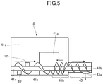
- FIG. 5 is a schematic configuration diagram of a communicating opening of the developing apparatus and its surroundings.
- FIG. 6 is a diagram illustrating a toner collection configuration of the first embodiment.
- FIG. 7 is a schematic configuration diagram illustrating a state where a seal is applied to the communicating opening of the developing apparatus of the first embodiment.
- FIG. 8 is a schematic cross-sectional view illustrating the state where the seal is applied to the communicating opening of the developing apparatus of the first embodiment.
- FIG. 9 is a control block diagram of the image forming apparatus of the first embodiment.
- FIG. 10 is a perspective view of a permeability sensor of the first embodiment.
- FIG. 11 is a graph illustrating a relationship between toner density and the output voltage of the permeability sensor.
- FIG. 12 is a diagram illustrating an operation process of the image forming apparatus of the first embodiment.
- FIG. 13 is a flowchart illustrating induction-detection toner supply control of the first embodiment.
- FIG. 14 is a flowchart illustrating an initializing operation of the developing apparatus of the first embodiment.
- FIG. 15 is a graph illustrating a relationship between accumulated supplied-developer amount and patch image forming interval.
- FIG. 16 is a graph illustrating a relationship of a second embodiment, between supplying-screw rotation time and carrier supply amount.
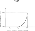
- FIG. 17 is a graph illustrating a relationship of the second embodiment, between the amount of developer of the developing apparatus and developer discharge speed.
- FIG. 18 is a graph illustrating a relationship of the second embodiment, between the amount of developer of the developing apparatus and patch image forming interval.
- FIG. 19 is a flowchart illustrating induction-detection toner supply control of the second embodiment.
- FIG. 20 is a flowchart illustrating laser power control of a third embodiment, performed for an exposure apparatus by using patch detection.
- FIG. 21 is a graph illustrating a relationship of the third embodiment, between accumulated supplied-developer amount and patch image forming interval.
- FIG. 22 is a graph illustrating a relationship of a fourth embodiment, between the amount of developer of the developing apparatus and patch image forming interval.
- FIG. 23 is a flowchart illustrating laser power control of the fourth embodiment, performed for an exposure apparatus by using patch detection.
- FIG. 24 is a flowchart illustrating a developer replacement mode of a fifth embodiment, performed by using average image ratio.
- FIG. 25 is a diagram illustrating an operation process of the image forming apparatus, of the fifth embodiment.
- FIG. 26 is a graph illustrating a relationship of the fifth embodiment, between accumulated supplied-developer amount and threshold of the average image ratio used for determining whether to perform the developer replacement mode.
- FIG. 27 is a graph illustrating a relationship of a sixth embodiment, between the amount of developer of the developing apparatus and threshold of the average image ratio used for determining whether to perform the developer replacement mode.
- FIG. 28 is a flowchart illustrating a developer replacement mode of the sixth embodiment, performed by using the average image ratio.
- FIG. 29 is a flowchart illustrating an idling mode of a seventh embodiment, performed by using accumulated supplied-developer amount.
- FIG. 30 is a graph illustrating a relationship of the seventh embodiment, between accumulated supplied-developer amount and idling-mode time.
- FIG. 31 is a graph illustrating a relationship of an eighth embodiment, between the amount of developer of the developing apparatus and idling-mode time.
- FIG. 32 is a flowchart illustrating an idling mode of the eighth embodiment, performed by using the amount of developer of the developing apparatus.
- FIGS. 1 to 15 A first embodiment will be described with reference to FIGS. 1 to 15 .
- a schematic configuration of an image forming apparatus of the present embodiment will be described with reference to FIGS. 1 and 2 .
- An image forming apparatus 100 is a tandem-type electrophotographic full-color printer.
- the image forming apparatus 100 includes four image forming portions PY, PM, PC, and PK, each having a photosensitive drum 1 which serves as an image bearing member.
- the image forming apparatus 100 forms a toner image (image) on a recording material, in accordance with an image signal sent from a document reading apparatus (not illustrated) connected to an apparatus body 100 A, or from a host device, such as a personal computer, communicatively connected to the apparatus body 100 A.
- the recording material may be a sheet material, such as a paper sheet, a plastic film, or a cloth sheet.
- the image forming portions PY, PM, PC, and PK respectively form toner images of yellow, magenta, cyan, and black.
- the four image forming portions PY, PM, PC, and PK of the image forming apparatus 100 are substantially the same as each other, except that they have different developing colors from each other.
- the image forming portion PK will be described as one example, and the description for the other image forming portions will be omitted.
- the image forming portion PK includes a cylindrical photosensitive member, or the photosensitive drum 1 as an image bearing member.
- the photosensitive drum 1 is rotated in a direction indicated by an arrow of FIG. 2 .
- a charging roller 2 which serves as a charging portion
- a developing apparatus 4 Around the photosensitive drum 1 , there are disposed a charging roller 2 which serves as a charging portion, a developing apparatus 4 , a primary transfer roller 52 which serves as a primary transfer portion, and a cleaning apparatus 7 which serves as a cleaning portion.
- an exposure apparatus 3 (a laser scanner in the present embodiment) is disposed as an exposure portion.
- an intermediate transfer apparatus 5 is disposed as a transfer portion.
- the intermediate transfer apparatus 5 is configured such that an endless intermediate transfer belt 51 , which serves as an intermediate transfer member, is wound around a plurality of rollers, and is revolved (rotated) in a direction indicated by an arrow of FIG. 1 .
- the intermediate transfer belt 51 carries and conveys a toner image which has been primary-transferred onto the intermediate transfer belt 51 .
- a secondary transfer outer roller 54 which serves as a secondary transfer member, is disposed at a position at which the secondary transfer outer roller 54 faces, via the intermediate transfer belt 51 , a secondary transfer inner roller 53 which is one of the rollers, around which the intermediate transfer belt 51 is wound.
- the secondary transfer outer roller 54 and the secondary transfer inner roller 53 constitute a secondary transfer portion T 2 , which transfers the toner image formed on the intermediate transfer belt 51 , onto the recording material.
- a fixing apparatus 6 is disposed downstream from the secondary transfer portion T 2 in a recording-material conveyance direction.
- a cassette 9 in which a recording material S is stored.
- the recording material S is fed from the cassette 9 and conveyed by a conveyance roller 10 toward a registration roller 11 .
- a conveyance roller 10 When the leading edge of the recording material S abuts against the registration roller 11 which is in a stop state, a loop is formed, and then skew of the recording material S is corrected.
- the registration roller 11 starts to rotate and conveys the recording material S to the secondary transfer portion T 2 , in synchronization with the conveyance of the toner image formed on the intermediate transfer belt 51 .
- the image forming process is performed to create a full-color image having four colors, for example.
- the surface of the rotating photosensitive drum 1 is uniformly charged by the charging roller 2 .
- the photosensitive drum 1 is then exposed to a laser beam emitted from the exposure apparatus 3 and corresponding to an image signal. With this operation, an electrostatic latent image is formed on the photosensitive drum 1 in accordance with the image signal.
- the electrostatic latent image on the photosensitive drum 1 is then made visible and becomes a visible image by using toner contained in the developing apparatus 4 and serving as developer.
- the toner image formed on the photosensitive drum 1 is then primary-transferred onto the intermediate transfer belt 51 in a primary transfer portion T 1 ( FIG. 2 ), constituted by the photosensitive drum 1 and a primary transfer roller 52 .
- the primary transfer roller 52 is disposed at a position at which the primary transfer roller 52 faces the photosensitive drum 1 via the intermediate transfer belt 51 .
- the primary transfer roller 52 is being applied with a primary transfer bias.
- Sticking substance, such as toner (remaining toner) left on the surface of the photosensitive drum 1 after the primary transfer, is removed by a cleaning apparatus 7 . With this operation, the photosensitive drum 1 is made ready for the next image forming process.
- Such an operation is performed sequentially in the image forming portions of yellow, magenta, cyan, and black; and four-color toner images are superposed on each other on the intermediate transfer belt 51 .
- the recording material S stored in the cassette 9 is conveyed to the secondary transfer portion T 2 in synchronization with the formation of the toner image.
- the four-color toner images on the intermediate transfer belt 51 are collectively secondary-transferred onto the recording material S.
- Sticking substance, such as toner not used for the secondary transfer in the secondary transfer portion T 2 and left on the intermediate transfer belt 51 is removed by an intermediate transfer belt cleaner 55 .
- the sticking substance, such as toner, removed by the cleaning apparatus 7 and the intermediate transfer belt cleaner 55 is conveyed through conveyance pipes 56 , and collected in a toner collection box 57 .
- Toner is supplied from a toner container 8 by the amount of toner consumed for forming images.
- the recording material S is then conveyed to the fixing apparatus 6 which serves as a fixing portion.
- the fixing apparatus 6 includes a fixing roller 61 having a heat source such as a halogen heater, and a pressure roller 62 .
- the fixing roller 61 and the pressure roller 62 form a fixing nip portion.
- the recording material S on which the toner image has been transferred is heated and pressurized.
- the toner on the recording material S is melted and mixed, and fixed to the recording material S as a full-color image.
- the recording material S is then discharged to a discharging tray 102 by a discharge roller 101 . With this operation, a series of image forming processes are completed.
- the image forming apparatus 100 of the present embodiment may form a monochrome image by using an image forming portion for a desired monochrome image, such as a black image, or may form a multicolor image by using image forming portions for some of the four colors.
- the developing apparatus 4 includes a developer container 41 which contains two-component developer containing nonmagnetic toner and magnetic carrier.
- the developer container 41 includes a developing sleeve 44 which serves as a developer bearing member and a magnet roll 44 a disposed in and fixed to the developing sleeve 44 .
- the magnet roll 44 a is a magnet which serves as a magnetic-field generating portion.
- the developer container 41 includes a developing blade 42 and agitating-and-conveying screws 41 d and 41 e .
- the developing blade 42 serves as a developer regulation member and forms a thin layer of developer on the surface of the developing sleeve 44 .
- the agitating-and-conveying screws 41 d and 41 e serve as conveyance portions and convey the developer of the developer container 41 while agitating the same.
- the interior of the developer container 41 is partitioned into a developing chamber 41 a which is a first chamber and an agitating chamber 41 b which is a second chamber, by a partition wall 41 c extending in a vertical direction.
- the agitating-and-conveying screw 41 d is disposed in the developing chamber 41 a
- the agitating-and-conveying screw 41 e is disposed in the agitating chamber 41 b .
- communicating openings 41 f and 41 g are formed to cause the developing chamber 41 a and the agitating chamber 41 b to communicate with each other.
- the communicating openings 41 f and 41 g allow the developer to flow from the developing chamber 41 a to the agitating chamber 41 b , and vice versa.
- the agitating-and-conveying screws 41 d and 41 e are both screw-like members. That is, each of the agitating-and-conveying screws 41 d and 41 e includes a magnetic rotation shaft and a spiral blade formed around the rotation shaft and serving as a conveyance portion.
- the agitating-and-conveying screw 41 e disposed in the agitating chamber 41 b further includes agitating ribs 12 in addition to the blade.
- the agitating ribs 12 protrude from the rotation shaft toward a radial direction of the shaft, and each has a predetermined width in the developer conveyance direction.
- the agitating ribs 12 agitate the developer with the rotation of the agitating-and-conveying screw 41 e.
- the agitating-and-conveying screw 41 d conveys the developer of the developing chamber 41 a , while agitating the developer.
- the agitating-and-conveying screw 41 e conveys supplying developer supplied by a later-described developer supplying mechanism 49 and the developer having been contained in the agitating chamber 41 b while agitating the supplied developer and the developer; and thereby equalizes toner density (i.e. ratio of a toner weight to a total weight of toner and carrier).
- the developer supplying mechanism 49 which serves as a supplying portion, performs auto toner replenisher (ATR) control.
- the supplying developer is supplied to the developing apparatus 4 , depending on an image ratio determined when an image is formed, a detection result determined by a later-described permeability sensor 45 , and a detection result of a patch image density determined by an image density sensor 90 ( FIGS. 1 and 2 ) used to detect the density of toner image.
- the agitating-and-conveying screws 41 d and 41 e are disposed substantially parallel to each other in a direction (i.e. development width direction) in which the rotation axis of the developing sleeve 44 extends.
- the agitating-and-conveying screw 41 d conveys the developer along the rotation axis of the developing sleeve 44 toward a direction opposite to a direction toward which the agitating-and-conveying screw 41 e conveys the developer.
- the developer is circulated through the communicating openings 41 f and 41 g , in the developer container 41 by the agitating-and-conveying screws 41 d and 41 e .
- the developer of the developing chamber 41 a whose toner density is reduced due to toner consumption in the developing process is moved through the one communicating opening 41 f (the left one in FIG. 3 ) to the agitating chamber 41 b by the conveyance force of the agitating-and-conveying screws 41 d and 41 e , and the developer of the agitating chamber 41 b whose toner is increased and agitated is moved through the other communicating opening 41 f (the right one in FIG. 3 ) to the developing chamber 41 a.
- the developing chamber 41 a of the developing apparatus 4 has a developing area (a facing area) which faces the photosensitive drum 1 and which is opened.
- the developing sleeve 44 is rotatably disposed in the opening of the developer container 41 such that one portion of the developing sleeve 44 is exposed.
- the developing sleeve 44 is made of a nonmagnetic material and is rotated in a direction indicated by an arrow of FIG. 4 when the developing operation is performed.
- a magnet roll 44 a is fixed to the developing sleeve 44 .
- the magnet roll 44 a serves as a magnetic-field generating portion and has a plurality of magnetic poles formed along the circumferential direction of the magnet roll 44 a.
- the developer of the developing chamber 41 a (first chamber) is supplied to the developing sleeve 44 by the agitating-and-conveying screw 41 d .
- the developer supplied to the developing sleeve 44 is carried by the developing sleeve 44 , by a predetermined amount, due to a magnetic field generated by the magnet roll 44 a , and thus an accumulated developer is formed on the developing sleeve 44 .
- the developing sleeve 44 When the developing sleeve 44 rotates, the accumulated two-component developer formed on the developing sleeve 44 contacts the developing blade 42 , then the thickness of the accumulated two-component developer is regulated by the developing blade 42 , and then the accumulated two-component developer is conveyed to the developing area that faces the photosensitive drum 1 . That is, the developing sleeve 44 carries the developer of the developing chamber 41 a and conveys the developer to the developing area that faces the photosensitive drum 1 .
- the developer on the developing sleeve 44 is napped in the developing area to form magnetic brush.
- toner of the developer is supplied to the photosensitive drum 1 , and thereby the electrostatic latent image on the photosensitive drum 1 is developed as a toner image.
- the developing sleeve 44 is commonly applied with a development bias voltage from a development bias power source (not illustrated) which serves as a voltage applying portion.
- the development bias voltage is a voltage in which a direct-current voltage is added with an alternate-current voltage.
- the rotational speed (process speed) of the photosensitive drum 1 of the image forming apparatus 100 of the present embodiment is 300 mm/sec
- the rotational speed of the developing sleeve 44 is 450 mm/sec.
- the toner and the carrier of the two-component developer of the developing apparatus 4 are agitated and charged by friction. Then the toner is supplied to the photosensitive drum 1 by the developing sleeve 44 to develop an electrostatic latent image on the photosensitive drum 1 . In this time, although the toner is consumed and supplied, the carrier is neither consumed nor supplied, and left in the developing apparatus 4 . Thus, since the carrier is agitated more in the developing apparatus 4 than the toner, the charging ability of the carrier easily deteriorates because of accumulation of additive, adhesion of wax, and toner spent.
- the amount of conveyance of the developer is decreased and reduces friction (rubbing amount) of the developer and the amount of charge of the toner becomes short and causes defective images.
- uneven density or fogged white will be produced in a formed image.
- the fogged white is a defect in which the toner sticks to an area of the photosensitive drum 1 in which no electrostatic latent image is formed.
- the developer supplying mechanism 49 includes a supplying screw 4 h to supply the developer from the toner container 8 , a motor 49 a to drive the supplying screw 4 h , and a conveyance screw 49 b to convey the developer, supplied via the supplying screw 4 h toward the developing apparatus 4 , to the agitating chamber 41 b .
- the conveyance screw 49 b is formed integrally with the agitating-and-conveying screw 41 e , and has the same axis as that of the agitating-and-conveying screw 41 e .
- the conveyance screw 49 b conveys the developer, supplied to a supplying chamber 49 c , to the agitating chamber 41 b in a forward direction.
- the supplying chamber 49 c has a supplying inlet which is connected to a conveyance path for the developer.
- the conveyance path extends from a position at which the supplying screw 4 h is disposed.
- the two-component developer containing the carrier is supplied by the developer supplying mechanism 49 , and excess two-component developer which has been supplied and gradually increased in the developing apparatus 4 is discharged by a later-described auto carrier refresh (ACR) mechanism 43 .
- ACR auto carrier refresh
- the two-component developer containing carrier is supplied and discharged in this configuration, the deterioration of carrier is prevented, and the developing property of the two-component developer of the developing apparatus 4 is kept constant. As a result, the deterioration of image quality due to change in the developing property of the developer can be prevented for a long time.
- the developer discharged by the ACR mechanism 43 is stored by the toner collection box 57 , together with the toner removed by the cleaning apparatus 7 and the intermediate transfer belt cleaner 55 .
- the ACR mechanism 43 which serves as a discharging portion to discharge the developer of the developing apparatus 4 , is disposed at an end portion of the agitating chamber 41 b in the developer conveyance direction.
- the agitating-and-conveying screw 41 e of the agitating chamber 41 b includes the spiral blade having fins and the agitating ribs 12 each formed like a plate. Each of the agitating ribs 12 is disposed perpendicular to the rotation shaft, between adjacent fins.
- a backing screw 41 h is formed at an end portion of the agitating-and-conveying screw 41 e in the developer conveyance direction.
- the backing screw 41 h has fins wound in an opposite direction so that the developer is conveyed in a direction opposite to the developer conveyance direction (forward direction).
- the fins of the backing screw 41 h have a pitch smaller than that of the other fins of the agitating-and-conveying screw 41 e , to increase conveyance force.
- the backing screw 41 h receives the developer, which has been conveyed in the forward direction and delivers the developer to the developing chamber 41 a through the communicating opening 41 g.
- the amount of developer of the developer container 41 tends to gradually increase because only the toner is consumed in the image forming operation.
- the height of the surface of the developer of the developer container 41 increases with the increase in the amount of the developer.
- the conveyance capability of the backing screw 41 h is exceeded. As a result, the developer climbs over the backing screw 41 h.
- the auto carrier refresh mechanism 43 Downstream from the backing screw 41 h , there is disposed the auto carrier refresh mechanism 43 which includes a small discharging screw 43 b having a conveyance capability to convey the developer in the forward direction and a developer outlet 43 a .
- the developer having climbed over the backing screw 41 h is conveyed to the developer outlet 43 a by the discharging screw 43 b and collected in the toner collection box 57 illustrated in FIG. 6 .
- the initial carrier is replaced with the carrier to be used for forming images.
- the ratio of the toner to the carrier of the supplying developer is 9:1.
- the developing apparatus 4 of the present embodiment can be detachably attached to the apparatus body 100 A ( FIG. 1 ).
- a developing apparatus whose life has been reached can be removed from the apparatus body 100 A, and another developing apparatus containing initial developer can be attached to the apparatus body 100 A.
- seals 46 which serve as sealing members are detachably attached to seal the communicating openings 41 f and 41 g , which are formed between the agitating chamber 41 b and the developing chamber 41 a . That is, the seals 46 seal the communicating openings 41 f and 41 g in a state where the agitating chamber 41 b (second chamber) contains the developer (initial developer) and are removed from the communicating openings 41 f and 41 g when the developing apparatus 4 is used.
- the seals 46 can be peeled off from slits 41 i 1 formed in a top cover 41 i of the developing apparatus 4 , so that the seals 46 can be removed even when the developing apparatus 4 is positioned with respect to a drum unit including the photosensitive drum 1 .
- urethane members 47 having elasticity are disposed at both sides of each of the slits 41 i 1 to sandwich the seals 46 .
- the drum unit includes the charging roller 2 , the cleaning apparatus 7 , and the photosensitive drum 1 , for example.
- the seals 46 to seal the communicating openings 41 f and 41 g which allow the developing chamber 41 a and the agitating chamber 41 b to communicate with each other, may be Mylar sheets.
- the Mylar sheets cover and heat-seal the communicating openings 41 f and 41 g .
- the seals 46 which may be Mylar sheets, protrude upward from the slits 41 i 1 of the top cover 41 i , sandwiched by the urethane members 47 . Thus, when the seals 46 are pulled upward and removed, the sealing is released.
- the communicating openings 41 f and 41 g are sealed by the seals 46 in the state where the agitating chamber 41 b contains the initial developer, the developer is prevented from leaking from a portion between the developing sleeve 44 and the developer container 41 , or a portion between the developing sleeve 44 and the developing blade 42 .
- soiling caused by the leakage of the developer can be prevented during delivery of the developing apparatus 4 .
- the configuration to enclose the initial developer has an advantage in which the seals 46 can be removed from a top portion or a side portion of the developer container 41 in a state where the developing apparatus 4 is in contact with the drum unit including the photosensitive drum 1 .
- a frame unit in which the developing apparatus 4 and the drum unit are set can be drawn from the front side of the apparatus body 100 A for maintenance of the developing apparatus 4 and the drum unit.
- the developing apparatus 4 and the drum unit are pressed toward each other to keep a constant developing nip distance between the developing sleeve 44 and the photosensitive drum 1 .
- the configuration that allows the seals 46 to be pulled upward and removed facilitates maintenance, because the above-described configuration, in which the developing apparatus 4 and the drum unit are pressed toward each other, needs not to be changed when the seals 46 are removed.
- the control portion 200 includes a central processing unit (CPU) 201 which serves as a control unit or a setting portion, and a memory 202 .
- the memory 202 includes a read only memory (ROM) 202 a .
- the ROM 202 a stores programs associated with control procedures.
- the CPU 201 controls each unit while reading the programs stored in the ROM 202 a .
- the memory 202 also includes a random access memory (RAM) 202 b which stores work data and input data.
- the CPU 201 performs control, depending on the above-described programs and referring to the data stored in the RAM 202 b.
- the CPU 201 is connected to an input/output (I/O) device 203 and an engine control portion 204 .
- the input/output device 203 sends/receives signals to/from a host device or the like.
- the engine control portion 204 receives instructions from the CPU 201 , and controls an image forming engine portion 205 of each image forming portion.
- the image forming engine portion 205 is used to form images, and includes the charging roller 2 , the exposure apparatus 3 , the developing apparatus 4 , the developer supplying mechanism 49 , the intermediate transfer apparatus 5 , and the fixing apparatus 6 .
- the engine control portion 204 is connected to a new-article detecting device 206 to detect whether the developing apparatus 4 is a new article or not.
- the engine control portion 204 detects whether the developing apparatus 4 is a new article or not, depending on a detection result by the new-article detecting device 206 .
- the developer supplying mechanism 49 includes the supplying screw 4 h , which is driven by the motor 49 a .
- the rotation of the motor 49 a is controlled by the engine control portion 204 .
- a relationship between the rotation time of the motor 49 a and the mount of toner supplied to the developer container 41 by the supplying screw 4 h has been determined in advance through an experiment.
- the relationship is stored, as table data, in the ROM 202 a connected to the CPU 201 , or included in the CPU 201 . That is, the CPU 201 adjusts the amount of toner to be supplied to the developer container 41 , by controlling (adjusting) the rotation time of the motor 49 a.
- the developer container 41 is provided with the permeability sensor (inductance sensor) 45 which serves as a toner-density detecting portion to detect the toner density of the developing apparatus 4 .
- the permeability sensor 45 is disposed downstream in the agitating chamber 41 b , in the direction in which the developer is conveyed by the agitating-and-conveying screw 41 e.
- a cylindrical detecting head 45 a is disposed on a sensor body 45 c , and is formed integrally with the same.
- the permeability sensor 45 sends/receives signals to/from the CPU 201 ( FIG. 9 ) of the image forming apparatus 100 , via a signal line 45 b used for input and output.
- the detecting head 45 a includes a detecting transformer.
- the detecting transformer includes three windings: a primary winding, a reference winding, and a detecting winding.
- the reference winding and the detecting winding constitute a secondary winding.
- the detecting winding is disposed on the top surface side of the detecting head 45 a
- the reference winding is disposed on the bottom surface side of the detecting head 45 a
- the primary winding is disposed between the detecting winding and the reference winding.
- the permeability sensor 45 causes a comparator of the sensor body 45 c to compare the current signal generated by the oscillator and having the predetermined waveform, with the current signal induced in the detecting winding due to the electromagnetic induction and having the waveform; and thereby detects the density of the magnetic material that exists near the top surface of the detecting head 45 a.
- FIG. 11 illustrates one example of the output characteristic of the permeability sensor 45 .
- the output voltage (sensor output) is saturated at a large value in a range where the toner density is small, gradually decreased as the toner density is increased, and saturated at a small value in a range where the toner density is large.
- the permeability sensor 45 is adjusted so as to output a voltage of about 2.5 V when the toner density has a normal value of 8% (weight percentage, which holds true also in the following description). In a range of voltages near 2.5 V, the output voltage changes almost linearly with respect to the toner density.
- the toner density of the developer of the developing apparatus 4 is detected by the permeability sensor 45 .
- the supplying screw 4 h ( FIG. 3 ) of the developer supplying mechanism 49 is driven, the supplying developer is supplied to the developing apparatus 4 , and thereby the toner density of the developing apparatus 4 is kept constant. That is, depending on the detection result by the permeability sensor 45 , the CPU 201 determines the rotation time of the motor 49 a , and rotates the motor 49 a for the rotation time.
- the ROM 202 a (or the CPU) stores information used to determine the amount of developer to be supplied to the developing apparatus 4 .
- the information is determined, depending on the relationship between the sensor output from the permeability sensor 45 illustrated in FIG. 11 and the toner density; and is stored as table data.
- the CPU 201 can use the information and table data indicating a relationship between the above-described rotation time of the motor 49 a and the amount of toner to be supplied, determine the number of rotations of the supplying screw 4 h , and thereby control the amount of developer to be supplied.
- the developer supplying control which uses the permeability sensor 45 and the inductance detecting method, determines the number of rotations of the supplying screw 4 h and supplies toner every time an image forming operation is performed on a single recording material.
- a target toner density of the present embodiment is 8% for all developers of yellow, magenta, cyan, and black.
- the toner collection box 57 collects the developer discharged from the cleaning apparatus 7 , the intermediate transfer belt cleaner 55 , and the auto carrier refresh mechanism 43 of the developing apparatus 4 .
- the toner collection box 57 includes a near end sensor 57 a which detects that the toner collection box 57 is nearly full of the toner. As the toner is accumulated in the toner collection box 57 , the surface of the powder rises and reaches the near end sensor 57 a . At this time, the CPU 201 determines that the toner collection box 57 is nearly full of the toner.
- the CPU 201 When the near end sensor 57 a detects that the toner collection box 57 is nearly full of the toner, the CPU 201 causes a control panel (not illustrated) of the image forming apparatus 100 to display a message instructing a user to prepare a new toner collection box. This message can inform the user that the toner collection box 57 is nearly full of the toner.
- the CPU 201 calculates an accumulated supplied-developer amount in which supplied developers of yellow, magenta, cyan, and black are totalized, and stores the accumulated supplied-developer amount.
- the CPU 201 determines that the toner collection box is full of the toner and causes the control panel to display a message instructing a user to replace the toner collection box with a new toner collection box. During this operation, the image forming operation is disabled.
- This process is performed in starting-operation time (warm-up time) for the image forming apparatus 100 .
- a power switch is turned on, preparatory operations of predetermined processing components are performed.
- a main motor of the image forming apparatus 100 is started, the photosensitive drum 1 is rotated, and the fixing apparatus 6 is heated to a predetermined temperature.
- the main motor is stopped, and the image forming apparatus 100 is kept in a standby mode until a print job (image forming job) start signal is received.
- This process is performed, before an image is formed, in a preparatory rotation time from when the print job start signal is received until when an actual image forming (or print) operation is started. More specifically, in this process, the print job start signal is received by the image forming apparatus 100 , then an image is developed by a formatter (the developing time depends on the amount of data of the image and the processing speed of the formatter), and then the pre-rotation process is started.
- the standby mode is not performed, and the pre-rotation process is performed after the initial rotation.
- the main motor is stopped after the initial rotation, the rotation of the photosensitive drum 1 is stopped, and the printer is kept in the standby mode until the print job start signal is received.
- the pre-rotation process is performed.
- an image forming process is performed on the rotating photosensitive drum 1 . Then, a toner image formed on the surface of the rotating photosensitive drum 1 is transferred onto a recording material via the intermediate transfer belt 51 , then the transferred toner image is fixed to the recording material by the fixing apparatus 6 , and then the formed image is printed out.
- the above-described printing process is repeated a predetermined number n of times equal to the number of sheets on which an image is to be formed.
- This process is performed, in a continuous printing job, in a period of time from when the trailing edge of a recording material passes a transfer position (of the secondary transfer portion T 2 ) until when the leading edge of the following recording material reaches the transfer position.
- the period of time corresponds to a gap between successive recording materials.
- the recording material may not be a paper sheet
- the period of time in which the recording material does not pass the transfer position is referred to as a paper sheet gap for convenience.
- the main motor is continuously driven for a predetermined period of time after an image-formed recording material is outputted in a printing job for a single sheet, or after an image-formed last recording material is outputted in a continuous printing job.
- post-operations of the predetermined processing components are performed after the printing job.
- the photosensitive drum 1 is rotated by the continuously-driven main motor to perform the predetermined post-operation, for the predetermined time even after the printing process for the last recording material is completed.
- the main motor is stopped to stop the rotation of the photosensitive drum 1 .
- the image forming apparatus 100 is then kept in a standby mode until the next print job start signal is received.
- the printer enters the standby mode after the printing and the post-rotation process are completed.
- the printer performs the pre-rotation process.
- an image is formed in the above-described printing process, and no image is formed in the above-described pre-rotation process with the large number of rotations, pre-rotation process, paper-sheet gap process, and post-rotation process.
- the period of time in which no image is formed corresponds to at least one of the above-described pre-rotation processes with the large number of rotations, pre-rotation process, paper-sheet gap process, and post-rotation process, or a predetermined time of the at least one of the above-described processes.
- the image forming apparatus 100 includes the image density sensor 90 , which serves as a density detecting portion and detects the density of a control toner image (patch image).
- the image density sensor 90 is disposed downstream from the image forming portion PK (which is one of the image forming portions and located most downstream); and faces an outer circumferential surface of the intermediate transfer belt 51 , located upstream from the secondary transfer portion T 2 .
- the image density sensor 90 detects the density of the patch image, which has been transferred onto the intermediate transfer belt 51 .
- patch detection forming the patch image and detecting the density of the patch image by using the image density sensor 90
- the developer supplying control is performed by using the patch detection (patch detecting method) and the above-described inductance detecting method.
- a predetermined reference latent image (patch latent image) is formed on the photosensitive drum 1 when no image is formed, and then a reference toner image (control toner image, or patch image) is formed on the photosensitive drum 1 by developing the predetermined reference latent image under a predetermined developing condition.
- the patch image is then transferred onto the intermediate transfer belt 51 , and the density of the patch image is detected by the image density sensor 90 .
- the image density sensor 90 sends a density signal indicating the patch image density (the amount of sticking toner), to the CPU 201 ( FIG. 9 ).
- the CPU 201 compares the density signal from the image density sensor 90 , with an initial reference signal pre-stored in the CPU 201 ; and performs later-described control, in accordance with a comparison result.
- the image density sensor 90 may use an ordinary reflective optical sensor.
- the CPU 201 reads a predetermined environment table (which stores set values for process conditions based on temperature and humidity information and set values for process conditions such as exposure intensity, developing bias, and transfer bias) stored in the ROM 202 a when the image forming apparatus 100 was installed.
- the charged photosensitive drum 1 is exposed to the laser beam in accordance with this table, to form the patch latent image, and a patch image is formed by developing the patch latent image.
- the CPU 201 corrects a target value (i.e. target inductance signal value corresponding to a target toner density) of the inductance detection signal detected by the permeability sensor 45 , by using a signal value of the patch image density detected by the image density sensor 90 .
- the amount of charge of the toner of the developer of the developing apparatus 4 significantly varies depending on long-term use, continuous use, change in use condition, deteriorated carrier, and the like. In this case, even though the toner density is kept constant, it may be difficult to keep stable image density and color.
- the CPU 201 corrects the target value of the inductance detection signal, as appropriate, by using the patch image density (detection result) detected by the image density sensor 90 .
- the amount of developer to be supplied from the developer supplying mechanism 49 is controlled.
- the CPU 201 controls the amount of developer to be supplied from the developer supplying mechanism 49 , depending on a detection result by the image density sensor 90 . With this operation, since the change in the amount of charge of the toner can be suppressed, significant change in image density can be suppressed.
- FIG. 13 is a flowchart illustrating processes from the start to the end of an image forming operation.
- a symbol T denotes the number of image-outputted sheets (the number of image-formed sheets) counted from when a patch image was formed in the last time by using the developing apparatus 4
- a symbol T_p denotes the number of sheets (frequency) which causes the patch image to be formed
- a symbol Ptrg1 denotes a target toner-image-density value (a target signal value) of the patch image.
- the target toner-image-density value Ptrg1 of the present embodiment is 500.
- a symbol Psig is an image-density signal value of the patch image
- a symbol Itrg(n) is a pre-correction target inductance signal value
- a symbol Itrg(n+1) is a post-correction target inductance signal value.
- the number of image-outputted sheets produced by using the developing apparatus 4 is calculated by the CPU 201 and stored in the memory 202 included in or connected to the CPU 201 .
- the CPU 201 After starting to form an image (S 1 ), the CPU 201 determines T_p in steps S 2 to S 4 . The steps S 2 to S 4 will be described later. The CPU 201 then determines whether the number T of image-outputted sheets counted from when a patch image was formed in the last time reaches T_p (S 5 ). If the number T of image-outputted sheets reaches T_p in S 5 (S 5 : Yes), then the CPU 201 forms a patch image, causes the image density sensor 90 to detect the density of the patch image, and calculates an image density Psig (S 6 ).
- the CPU 201 determines whether the relationship between the detected image density Psig of the patch image and the target toner-image-density value Ptrg1 satisfies Ptrg1 ⁇ Psig (S 7 ). If the relationship does not satisfy the above-described expression, that is, if Ptrg1>Psig (S 7 : No), then the CPU 201 changes the target inductance signal value (target toner density) (S 8 ). Specifically, the CPU 201 subtracts 0.15 V (which corresponds to a toner density of 0.5%) from Itrg(n), and sets the resulting value (Itrg(n) ⁇ 0.15) to the post-corrected target inductance signal value Itrg(n+1) (S 8 ).
- the CPU 201 increases the density of the toner of the developing apparatus 4 , by using the relationship illustrated in FIG. 11 and decreasing the target inductance signal value.
- the toner density is increased, the toner contacts the carrier less frequently, which decreases the amount of charge of the toner.
- the CPU 201 determines whether the relationship between the patch image density Psig and the target toner-image-density value Ptrg1 satisfies Psig ⁇ Ptrg1 (S 9 ). If the relationship does not satisfy the above-described expression, that is, if Psig>Ptrg1 (S 9 : No), then the CPU 201 changes the target inductance signal value (target toner density) (S 10 ).
- the CPU 201 adds 0.15 V (which corresponds to a toner density of 0.5%) to the target inductance signal value Itrg(n) and sets the resulting value (Itrg(n)+0.15) to the post-corrected target inductance signal value Itrg(n+1) (S 10 ).
- the CPU 201 decreases the density of the toner of the developing apparatus 4 , by using the relationship illustrated in FIG. 11 and increasing the target inductance signal value.
- the toner density is decreased, the toner contacts the carrier more frequently, which increases the amount of charge of the toner.
- the CPU 201 determines whether the image forming operation is completed (S 11 ).
- the CPU 201 ends the image forming process (S 12 ) if the image forming operation is completed (S 11 : Yes), or returns to S 5 if not (S 11 : No).
- Psig is equal to Ptrg1.
- the target inductance signal value target toner density
- the CPU 201 does not change the target inductance signal value (target toner density), and continues to form images.
- the CPU 201 determines whether the image forming operation is completed (S 13 ). The CPU 201 ends the image forming process (S 14 ) if the image forming operation is completed (S 13 : Yes), or returns to S 5 if not (S 13 : No).
- upper and lower limits of the above-described target inductance signal value Itrg are provided.
- the upper and lower limits are 2.5 ⁇ 0.6 V (which correspond to toner densities of 8 ⁇ 2%).
- the upper and lower limits are provided because toner fog and toner fly may occur when the toner density is extremely high, and carrier sticking and rough image may occur when the toner density is extremely low.
- Ptrg1 ⁇ Psig Itrg(n+1) does not become larger than 3.1 V
- Ptrg1>Psig Itrg(n+1) does not become smaller than 1.9 V.
- Itrg(n+1) is 3.1 V or 1.9 V (that is, fixed to 3.1 V or 1.9 V).
- the toner supply control using the inductance detecting method is corrected by using the patch detecting method.
- the inductance detecting method typically determines the number of rotations of the supplying screw 4 h and supplies toner every time an image forming operation is performed on the single recording material S.
- the developing apparatus 4 includes a fuse which is the new-article detecting device 206 ( FIG. 9 ), and a board terminal of the fuse is in contact with a contact of the apparatus body of the image forming apparatus 100 .
- a fuse which is the new-article detecting device 206 ( FIG. 9 )
- a board terminal of the fuse is in contact with a contact of the apparatus body of the image forming apparatus 100 .
- the engine control portion 204 determines that the developing apparatus 4 is a new article. If the developing apparatus 4 is not a new article, the current does not flow through the fuse because the fuse has already been blown. In this case, the engine control portion 204 determines that the developing apparatus 4 is a used article.
- the image forming apparatus 100 performs an initializing operation after the power is turned on.
- the initializing operation when the power for the image forming apparatus 100 is turned on (S 21 ), the CPU 201 causes the developing apparatus 4 to run idle for a predetermined period of time, so that the developer of the developing apparatus 4 is uniformly distributed in the developer container, and that the amount of charge of the developer is increased (S 22 ). In the present embodiment, the CPU 201 causes the developing apparatus 4 to run idle for 60 seconds.
- the developing apparatus 4 is activated in a state where the other units, such as the photosensitive drum 1 , the intermediate transfer belt 51 , and the fixing apparatus 6 , are deactivated, and where high voltages used for various purposes are turned off; and the agitating-and-conveying screws 41 d and 41 e are rotated.
- the developing apparatus 4 may be activated in a state where no image is formed (no electrostatic latent image is formed, that is, a so-called solid white image is formed).
- the developing sleeve 44 and the agitating-and-conveying screws 41 d and 41 e can be separately driven, at least the agitating-and-conveying screws 41 d and 41 e may be rotated in the idling operation.
- the CPU 201 sets conditions for the permeability sensor 45 (S 23 ). In the present embodiment, after the idling operation for 60 seconds, the CPU 201 causes the developing apparatus 4 to run idle for 1 second without stopping the developing apparatus 4 . In this period of time, the CPU 201 receives output values from the permeability sensor 45 , 20 times, at intervals of 50 milliseconds. The CPU 201 then calculates an average detection value of the twenty output values and stores the average detection value in the CPU 201 , as a target value of the permeability sensor 45 .
- the CPU 201 sets a patch image forming condition (S 24 ). Then, a patch image (toner test pattern) formed under predetermined image-forming conditions (charging voltage for the photosensitive drum 1 , development bias voltage, transfer voltage, exposure amount) is formed on the photosensitive drum 1 . The patch image is then transferred onto the intermediate transfer belt 51 , then the density of the patch image is detected by the image density sensor 90 , and then the toner-image-density signal value detected by the image density sensor 90 is stored in the CPU 201 , as a target value.
- the CPU 201 sets image forming conditions (S 25 ). Patch images (toner test patterns) formed under predetermined image-forming conditions (charging voltage for the photosensitive drum 1 , development bias voltage, transfer voltage, gradation correction table, etc.) are formed on the photosensitive drum 1 . The patch images are formed with a plurality of different exposure amounts (low density and medium density). Then, the patch images are transferred onto the intermediate transfer belt 51 , and the CPU 201 causes the image density sensor 90 to estimate output values (optimum charging voltage, optimum development bias voltage, optimum transfer voltage, and optimum gradation correction table). The CPU 201 then causes the image forming apparatus 100 to enter the standby mode again and completes the initializing operation (S 26 ).
- image forming conditions Charging voltage for the photosensitive drum 1 , development bias voltage, transfer voltage, gradation correction table, etc.
- the new developing apparatus 4 contains the developer by predetermined amount (120 g in the present embodiment).
- the developing apparatus 4 of the present embodiment causes the auto carrier refresh mechanism 43 to discharge the developer when the amount of developer of the developing apparatus 4 is 150 g or more.
- the amount (120 g) of the developer contained in the agitating chamber 41 b in a state where the communicating openings 41 f and 41 g are sealed by the seals 46 is smaller than the amount (150 g) of the developer obtained when the auto carrier refresh mechanism 43 starts to discharge the developer in use of the developing apparatus 4 .
- the amount of developer of the developing apparatus 4 is 120 g. After that, as the image forming operation proceeds, toner and carrier will be supplied to the developing apparatus 4 by the developer supplying mechanism 49 . In addition, when the amount of developer of the developing apparatus 4 reaches 150 g, the auto carrier refresh mechanism 43 starts to discharge the developer.
- the developing apparatus 4 When the developing apparatus 4 is attached to the apparatus body 100 A of the image forming apparatus 100 , and the power is turned on, the developing apparatus 4 is detected as a new article, and the above-described initializing operation is performed.
- the developer of the agitating chamber 41 b flows downstream in the agitating chamber 41 b , and gradually flows to the developing chamber 41 a and the surface of the developing sleeve 44 . Eventually, the developer spreads uniformly in the developer container 41 .
- the amount of developer of the developing apparatus 4 is large (120 g or more in the present embodiment), some developer may climb over the backing screw 41 h with the aid of the auto carrier refresh mechanism 43 and may be discharged from the developer outlet 43 a ( FIG. 5 ). Thus, if the developer of the developing apparatus 4 is discharged, the toner collection box 57 will be replaced sooner. In addition, since the discharged developer is not used for forming images, it will be uselessly disposed of. For these reasons, in the present embodiment, the amount of developer of the developing apparatus 4 is 120 g.
- the amount of initial developer of the developing apparatus 4 is reduced. In this manner, the developer is prevented from being discharged in the idling operation.
- the frequency of forming the patch image is changed in accordance with the amount of carrier supplied to the developing apparatus 4 , that is, the amount of developer of the developing apparatus 4 . Specifically, the frequency of forming the patch image is increased when the amount of developer is small and decreased when the amount of developer is increased due to a long-time image forming operation.
- the frequency of forming the patch image corresponds to the number of image-formed sheets between the patch images in a successive image forming process, which causes the patch image to be formed.
- the ratio of the toner to the carrier of the supplying developer is 9:1.
- the present embodiment uses an accumulated supplied-developer amount H_s calculated from the initializing operation of the developing apparatus 4 , as information on the amount of developer of the developing apparatus 4 and changes the frequency of forming the patch image.
- the frequency of forming the patch image corresponds to the number of image-formed sheets which causes the patch image to be formed. That is, the information on the amount of developer of the developing apparatus 4 indicates the amount of developer (accumulated supplied-developer amount H_s) supplied by the developer supplying mechanism 49 from when the seals 46 are removed and the use of the developing apparatus 4 is started. Specifically, as illustrated in FIG. 13 , after starting to form an image (S 1 ), the CPU 201 determines whether 0 ⁇ H_s ⁇ 300 g is satisfied (S 2 ).
- the CPU 201 determines the number T_p of image-formed sheets which causes the patch image to be formed (that is, patch image forming interval), depending on a table of FIG. 15 (S 3 ). That is, the CPU 201 changes the frequency of forming the patch image (patch image forming interval T_p), in accordance with the accumulated supplied-developer amount H_s, in a period of time from when the seals 46 are removed and the use of the developing apparatus 4 is started, until when the amount of developer of the developer container 41 reaches the predetermined amount of developer (150 g).
- the CPU 201 makes the frequency of forming the patch image higher at a second amount of developer of the developing apparatus 4 than that at a first amount of developer larger than the second amount. That is, when the accumulated supplied-developer amount H_s is small (the amount of developer of the developing apparatus 4 is small), the frequency of forming the patch image becomes high. In other words, when an image is successively formed on sheets, and when the patch image is formed by the developing apparatus 4 every time the image is formed on a predetermined number of sheets, the CPU 201 controls forming of the patch image, as follows.
- the CPU 201 controls forming of the patch image so that the predetermined number of image-formed sheets is a first number of image-formed sheets in a period of time from when the use of the developing apparatus 4 is started, until when the amount of developer of the developing apparatus 4 reaches a set value which is larger than the amount of initial developer of the developing apparatus 4 obtained before the developing apparatus 4 is used.
- the CPU 201 controls forming of the patch image so that the predetermined number of image-formed sheets is a second number of image-formed sheets which is larger than the first number of image-formed images, after the amount of developer of the developing apparatus 4 reaches the set value. If H_s ⁇ 300 g (S 2 : No), the CPU 201 sets 250 to T_p (S 4 ).
- the CPU 201 adjusts the amount of toner to be supplied to the developer container 41 , by controlling (adjusting) the rotation time of the motor 49 a . Since the rotation time of the motor 49 a corresponds to the number of rotations of the supplying screw 4 h , the accumulated supplied-developer amount H_s can be calculated from the rotation time of the motor 49 a . That is, when the number of rotations of the supplying screw 4 h reaches a predetermined value, the amount of developer of the developing apparatus 4 reaches the set value.
- the number of rotations of the supplying screw 4 h may correspond not to the rotation time of the motor 49 a , but to the number of rotations of the motor 49 a .
- the information on the amount of developer of the developing apparatus 4 may be the rotation time of the motor 49 a.
- the frequency of forming the patch image is changed in accordance with the amount of developer, and thereby the amount of charge of the toner of the developing apparatus 4 can be detected at high frequency and optimized.
- the defective images which are easily produced when the amount of developer of the developing apparatus 4 is small. For example, unstable image density, toner fly, fogged white, and rough image can be suppressed. That is, the defective images can be suppressed in accordance with the amount of developer of the developing apparatus 4 .
- the accumulated supplied-developer amount H_s is used as information on the amount of developer of the developing apparatus 4 , for determining the frequency of forming the patch image.
- the present disclosure is not limited to this.
- a video count value may be used as information on the amount of developer of the developing apparatus 4 .
- the video count value is a value obtained by totalizing levels (for example, each level has a value of 0 to 255) of the pixels of an image of inputted image data. Since the amount of developer to be supplied can be estimated from image information such as the video count value, the same effects can be produced even when the frequency of forming the patch image is determined by using the video count value.
- the frequency of forming the patch image may be determined by using the amount of supplied carrier because the amount of developer of the developing apparatus 4 can be estimated by using the amount of supplied carrier.
- the developer is discharged when the amount of developer of the developing apparatus 4 is 150 g or more.
- a slight amount of developer (for example, about 30 mg/min or less) may leak even when the amount of developer of the developing apparatus 4 is less than 150 g. Such slight leakage of the developer is not regarded as the discharge of the developer.
- the second embodiment differs from the first embodiment in that the frequency of forming the patch image is changed even when the amount of developer of the developing apparatus 4 is larger than the amount of developer obtained when the auto carrier refresh mechanism 43 starts to discharge the developer. Since the other configuration and operation are the same as those of the first embodiment, duplicated description and illustration will be omitted or simplified, and different features from the first embodiment will be mainly described.
- the amount of initial developer of the developing apparatus 4 is about 120 g, and the auto carrier refresh mechanism 43 of the developing apparatus 4 starts to discharge the developer when the amount of developer of the developing apparatus 4 reaches 150 g.
- the amount of developer (carrier) discharged from the developing apparatus 4 per unit time may be smaller than the amount of carrier supplied per unit time. For example, this case may occur when a solid image is successively formed on sheets.
- the solid image is an image formed in a predetermined-size image forming area at an image ratio (print ratio) of 100%.
- the amount of developer of the developing apparatus 4 increases.
- the amount of developer increases up to 180 g. This is because, when the amount of developer is 180 g, the supply speed of the carrier supplied when the solid image is successively formed on sheets becomes substantially equal to the discharge speed of the developer.
- the maximum amount of developer predetermined amount of developer, up to which the frequency of forming the patch image is increased, is 180 g.
- the frequency of forming the patch image is changed in accordance with the amount of developer of the developing apparatus 4 when the amount of developer of the developing apparatus 4 is in a range from 120 to 150 g as in the first embodiment, and also when the amount of developer of the developing apparatus 4 is in a range from 150 to 180 g. Specifically, the frequency of forming the patch image is increased as the amount of developer of the developing apparatus 4 decreases.
- the detailed description thereof will be made.
- FIG. 16 illustrates a relationship between the rotation time of the supplying screw 4 h ( FIG. 3 ) and the amount of supplied carrier.
- the amount of supplied carrier can be calculated from the rotation time of the supplying screw 4 h .
- FIG. 17 illustrates a relationship between the amount of developer of the developing apparatus 4 and the speed of the developer discharged from the developing apparatus 4 by the auto carrier refresh mechanism 43 .
- the developer discharge speed can be calculated from the amount of developer.
- the amount of carrier supplied per unit time and the amount of carrier discharged from the developing apparatus 4 can be determined, and thereby the amount M_a of developer of the developing apparatus 4 can be calculated.
- the amount of developer is in a range from 120 to 150 g
- the amount of discharged developer is zero as in the first embodiment
- the amount of supplied carrier calculated by using FIG. 16 is added to the amount M_a of developer.
- the amount M_a of developer calculated by using the tables of FIGS. 16 and 17 is the information on the amount of developer of the developing apparatus 4 .
- the amount of developer of the developing apparatus 4 is 170 g at a predetermined time. Then, an image forming operation is performed. In the image forming operation, the developing apparatus 4 is operated for 10 seconds, and the supplying screw 4 h is rotated for 5 seconds. In this case, by using FIG. 16 , the amount of supplied carrier obtained when the supplying screw 4 h is rotated for 5 seconds is calculated as 250 mg; and by using the table of FIG. 17 , the developer discharge amount obtained when the developing apparatus 4 contains 170 g of the developer and is operated for 10 seconds is calculated as 180 mg. Thus, since the difference 70 mg between the amount of supplied carrier 250 mg and the amount of discharged developer 180 mg is added to 170 g, the amount M_a of developer of the developing apparatus 4 obtained after the image forming job is completed is calculated as 170.07 g.
- FIG. 19 is a flowchart illustrating processes from the start to the end of an image forming operation.
- symbols used in FIG. 19 are the same as those used in FIG. 13 .
- the target toner-image-density value Ptrg1 is 500
- the number of image-outputted sheets produced by using the developing apparatus 4 is calculated by the CPU 201 , and stored in the memory 202 included in or connected to the CPU 201 .
- the CPU 201 After starting to form an image (S 1 ), the CPU 201 refers to the tables of FIGS. 16 and 17 , and calculates the amount M_a of developer of the developing apparatus 4 (S 31 ). The CPU 201 then uses the table of FIG. 18 , and determines T_p (S 32 ). As illustrated in FIG. 18 , the CPU 201 makes the frequency of forming the patch image, higher at a second amount of developer of the developing apparatus 4 than that at a first amount of developer larger than the second amount.
- the steps S 5 to S 14 are the same as the steps S 5 to S 14 of FIG. 13 of the first embodiment.
- the third embodiment differs from the first embodiment in that the laser power (exposure amount) of the exposure apparatus 3 is controlled in the image forming operation in accordance with the patch image density (detection result) detected by the image density sensor 90 . Since the other configuration and operation are the same as those of the first embodiment, duplicated description and illustration will be omitted or simplified, and different features from the first embodiment will be mainly described.
- the target value of the inductance detection signal is corrected in accordance with the patch image density detected by the image density sensor 90 , to suppress change in the amount of charge of the toner and change in the image density.
- the laser power of the exposure apparatus 3 is corrected as appropriate in the image forming operation in accordance with the patch image density (detection result) detected by the image density sensor 90 , to suppress change in the image density caused by change in the amount of charge of the toner.
- a predetermined reference latent image (patch latent image) is formed on the photosensitive drum 1 when no image is formed, and then a patch image (control toner image, or reference toner image) is formed on the photosensitive drum 1 by developing the predetermined reference latent image under a predetermined developing condition.
- the patch image is then transferred onto the intermediate transfer belt 51 , and the density of the patch image is detected by the image density sensor 90 .
- the image density sensor 90 sends a density signal indicating a patch image density (the amount of sticking toner), to the CPU 201 ( FIG. 9 ).
- the CPU 201 compares the density signal from the image density sensor 90 , with an initial reference signal pre-stored in the CPU 201 ; and performs later-described control, in accordance with a comparison result.
- the CPU 201 reads a predetermined environment table (which stores set values for process conditions based on temperature and humidity information and set values for process conditions such as exposure intensity, developing bias, and transfer bias) stored in the ROM 202 a when the image forming apparatus 100 was installed.
- the charged photosensitive drum 1 is exposed to the laser beam in accordance with this table, to form the patch latent image; and the patch image is formed by developing the patch latent image.
- the laser power control in the present embodiment will be described with reference to FIG. 20 .
- the amount of charge of the toner of the developer changes due to long-term use, continuous use, change in use condition, and the like.
- the laser power of the exposure apparatus 3 is controlled as appropriate in the image forming operation in accordance with the patch image density detected by the image density sensor 90 . Since the exposure is performed with the laser power determined in accordance with the change in the amount of charge of the toner, an image having appropriate image density is outputted.
- a symbol K denotes the number of image-outputted sheets (the number of image-formed sheets) counted from when a patch image was formed in the last time by using the developing apparatus 4
- a symbol T_ 1 denotes the number of sheets (frequency) which causes the patch image to be formed
- a symbol Ftrg1 denotes a target toner-image-density value (a target signal value) of the patch image.
- the target toner-image-density value Ftrg1 of the present embodiment is 500.
- a symbol Fsig denotes an image-density signal value of the patch image
- a symbol LP denotes a laser power of the exposure apparatus 3 .
- the minimum level of the laser power is 128, and the maximum level of the same is 255.
- the number of image-outputted sheets produced by using the developing apparatus 4 is calculated by the CPU 201 and stored in the memory 202 included in or connected to the CPU 201 .
- the CPU 201 After starting to form an image (S 41 ), the CPU 201 determines T_ 1 in steps S 42 to S 44 . The steps S 42 to S 44 will be described later. The CPU 201 then determines whether the number K of image-outputted sheets counted from when a patch image was formed in the last time reaches T_ 1 (S 45 ). If the number K of image-outputted sheets reaches T_ 1 in S 45 (S 45 : Yes), then the CPU 201 forms a patch image, causes the image density sensor 90 to detect the density of the patch image, and calculates the image density Fsig (S 46 ).
- the CPU 201 determines whether the relationship between the detected image density Fsig of the patch image and the target toner-image-density value Ftrg1 satisfies Ftrg1 ⁇ Fsig (S 47 ). If the relationship does not satisfy Ftrg1 ⁇ Fsig, that is, if Ftrg1>Fsig (S 47 : No), the laser power (exposure amount) LP of the exposure apparatus 3 is changed (S 48 ). Specifically, the level of the laser power LP of the exposure apparatus 3 is increased by 10 (S 48 ).
- the amount of charge of the toner of the developing apparatus 4 is large.
- the laser power LP is increased, so that an image having a desired density is obtained even when the amount of charge of the toner is large. That is, when the laser power LP is increased, a potential difference (developing contrast) between a potential of an exposed portion of the photosensitive drum 1 and a direct-current voltage (developing potential) of developing bias of the developing apparatus 4 becomes large. Consequently, the image density can be increased even when the image density is low due to the large amount of charge of the toner.
- the CPU 201 determines whether the relationship between the patch image density Fsig and the target toner-image-density value Ftrg1 satisfies Fsig ⁇ Ftrg1 (S 49 ). If the relationship does not satisfy Fsig ⁇ Ftrg1 in S 49 , that is, if Fsig>Ftrg1 (S 49 : No), the laser power (exposure amount) LP of the exposure apparatus 3 is changed (S 50 ). Specifically, the level of the laser power LP of the exposure apparatus 3 is decreased by 10 (S 50 ).
- the image density Fsig of the patch image is higher than the target toner-image-density value Ftrg1, the amount of charge of the toner of the developing apparatus 4 is small.
- the laser power LP is decreased, so that an image having a desired density is obtained even when the amount of charge of the toner is small. That is, when the laser power LP is decreased, the developing contrast is decreased. Consequently, the image density can be decreased even when the image density is high due to the small amount of charge of the toner.
- the minimum level is 128 and the maximum level is 255.
- the corrected value of the laser power becomes larger than 255 or smaller than 128, the corrected value will be fixed to 255 or 128.
- the CPU 201 determines whether the image forming operation is completed (S 51 ).
- the CPU 201 ends the image forming process (S 52 ) if the image forming operation is completed (S 51 : Yes) or returns to S 45 if not (S 51 : No).
- Ftrg1 ⁇ Fsig in S 47 and Fsig ⁇ Ftrg1 in S 49 , Fsig is equal to Ftrg1.
- the laser power (exposure amount) LP needs not to be changed, the image forming operation will be continued with the same laser power (exposure amount) LP.
- the CPU 201 determines whether the image forming operation is completed (S 53 ). The CPU 201 ends the image forming process (S 54 ) if the image forming operation is completed (S 53 : Yes) or returns to S 45 if not (S 53 : No).
- the ratio of the toner to the carrier of the supplying developer is 9:1.
- the present embodiment also uses the accumulated supplied-developer amount H_s calculated from when the initializing operation of the developing apparatus 4 is completed, as information on the amount of developer of the developing apparatus 4 ; and changes the frequency of forming the patch image.
- the frequency of forming the patch image corresponds to the number of image-formed sheets which causes the patch image to be formed. Specifically, as illustrated in FIG. 20 , after starting to form an image (S 41 ), the CPU 201 determines whether 0 ⁇ H_s ⁇ 300 g is satisfied (S 42 ).
- the CPU 201 determines the number T_ 1 of image-formed sheets which causes the patch image to be formed (that is, patch image forming interval), depending on the table of FIG. 21 (S 43 ).
- the CPU 201 makes the frequency of forming the patch image, higher at a second amount of developer of the developing apparatus 4 than that at a first amount of developer larger than the second amount. That is, when the accumulated supplied-developer amount H_s is small (the amount of developer of the developing apparatus 4 is small), the frequency of forming the patch image becomes high. In other words, when an image is successively formed on sheets, and when the patch image is formed by the developing apparatus 4 every time the image is formed on a predetermined number of sheets, the CPU 201 controls forming of the patch image, as follows.
- the CPU 201 controls forming of the patch image so that the predetermined number of image-formed sheets is a first number of image-formed sheets in a period of time from when the use of the developing apparatus 4 is started, until when the amount of developer of the developing apparatus 4 reaches a set value which is larger than the amount of initial developer of the developing apparatus 4 obtained before the developing apparatus 4 is used.
- the CPU 201 controls forming of the patch image so that the predetermined number of image-formed sheets is a second number of image-formed sheets which is larger than the first number of image-formed images, after the amount of developer of the developing apparatus 4 reaches the set value. If H_s ⁇ 300 g (S 42 : No), the CPU 201 sets 200 to T_ 1 (S 44 ).
- the frequency of forming the patch image is changed in accordance with the amount of developer, and thereby the laser power of the exposure apparatus 3 is changed as appropriate.
- the change in image density, caused by the change in the amount of charge of the toner can be suppressed. That is, the defective images can be suppressed in accordance with the amount of developer of the developing apparatus 4 .
- the fourth embodiment differs from the third embodiment in that the frequency of forming the patch image is changed even when the amount of developer of the developing apparatus 4 is larger than the amount of developer obtained when the auto carrier refresh mechanism 43 starts to discharge the developer. Since the other configuration and operation are the same as those of the third embodiment, duplicated description and illustration will be omitted or simplified, and different features from the third embodiment will be mainly described.
- the maximum amount of developer (predetermined amount of developer), up to which the frequency of forming the patch image is increased, is 180 g as in the second embodiment. That is, in the present embodiment, the frequency of forming the patch image is changed to adjust the laser power of the exposure apparatus 3 , when the amount of developer of the developing apparatus 4 is in a range from 120 to 150 g as in the first embodiment, and also when the amount of developer of the developing apparatus 4 is in a range from 150 to 180 g. Specifically, the frequency of forming the patch image is increased as the amount of developer of the developing apparatus 4 decreases.
- the detailed description thereof will be made.
- the amount of carrier supplied per unit time and the amount of carrier discharged from the developing apparatus 4 can be determined, and thereby the amount M_a of developer of the developing apparatus 4 can be calculated.
- the amount of developer is in a range from 120 to 150 g
- the amount of discharged developer is zero as in the first embodiment, and the amount of supplied carrier calculated by using FIG. 16 is added to the amount of developer.
- the laser power control of the present embodiment will be described with reference to FIGS. 22 and 23 .
- symbols used in FIG. 23 are the same as those used in FIG. 20 .
- the target toner-image-density value Ftrg1 is 500
- the minimum level of the laser power is 128, and the maximum level of the same is 255.
- the number of image-outputted sheets produced by using the developing apparatus 4 is calculated by the CPU 201 and stored in the memory 202 included in or connected to the CPU 201 .
- the CPU 201 After starting to form an image (S 41 ), the CPU 201 refers to the tables of FIGS. 16 and 17 and calculates the amount M_a of developer of the developing apparatus 4 (S 411 ). Then the CPU 201 determines T_ 1 by using the table of FIG. 22 (S 412 ). As illustrated in FIG. 22 , the CPU 201 makes the frequency of forming the patch image, higher at a second amount of developer of the developing apparatus 4 than that at a first amount of developer larger than the second amount.
- the steps S 45 to S 54 are the same as the steps S 45 to S 54 of FIG. 20 of the third embodiment.
- the fifth embodiment differs from the first embodiment in that the developer is forced to be consumed in a developer replacement mode, and that the amount of developer forced to be consumed is determined depending on an average image ratio and the accumulated supplied-developer amount H_s. Since the other configuration and operation are the same as those of the first embodiment, duplicated description and illustration will be omitted or simplified, and different features from the first embodiment will be mainly described.
- the toner of the developing apparatus 4 is hardly replaced.
- the toner will stay and circulate in the developing apparatus 4 for a long time. If the toner stays in the developing apparatus 4 for a long time, the toner will be repeatedly rubbed and agitated in the developing apparatus 4 for the long time and charged up.
- the shape of toner particles will become uneven, and the additive added to the developer for increasing flowability of the developer will be buried in surfaces of the toner particles. As a result, defective images will be easily produced. For example, developing performance by the toner is decreased, transfer efficiency is decreased, the image density is decreased, and rough images are produced.
- the CPU 201 which serves as a discharging control portion can perform a developer replacement mode in which the developer is discharged. That is, the CPU 201 calculates an image ratio of an image which is being formed and performs the developer replacement mode when detecting that the calculated image ratio is smaller than a predetermined value.
- the developer replacement mode the developer of the developing apparatus 4 is forced to be consumed, and the supplying developer is supplied to the developing apparatus 4 by the developer supplying mechanism 49 .
- an electrostatic latent image formed on a non-image area is developed by using a predetermined amount of toner to consume the toner of the developing apparatus 4 , and the supplying toner is newly supplied to the developing apparatus 4 by the amount of consumed toner by the developer supplying mechanism 49 , so that the deteriorated toner is replaced with the new toner.
- the image forming apparatus of the present embodiment uses a so-called video counting method, which can estimate the amount of toner to be consumed, by using a video count value of the image density of an image signal having been read by a CCD or the like. That is, a video count value of a single document is determined by detecting a level of each pixel of an output signal from an image signal processing circuit and totalizing detected values of the pixels that define the size of the document sheet. For example, the maximum video count value for a single A4-size sheet is 3884 ⁇ 106 in 400 dpi and 256-step gradation. The average image ratio can be calculated by multiplying the video count value by the number of image-formed sheets.
- the developer replacement mode will be described in detail below.
- the toner when an image having a low image ratio is successively formed on sheets, the toner is forced to be consumed to replace the toner, for preventing deterioration of the toner and image quality.
- the flow of the control will be described with reference to FIGS. 24 and 25 .
- the CPU 201 determines, in S 62 to S 64 , a threshold m (%) of the average image ratio used for determining whether to perform the developer replacement mode. The steps S 62 to S 64 will be described later.
- the CPU 201 then reads inputted image data, calculates an image ratio of the image by using its video count value, and stores the image ratio in the ROM 202 a .
- the ROM 202 a sequentially stores images ratios of previously-read one-hundred images (or previously-read predetermined number of images) including the image ratio of the image data.
- the CPU 201 reads the image ratios of the previously-read one-hundred images from the ROM 202 a and calculates an average image ratio n (%) of the previously-read one-hundred images (S 65 ).
- the average image ratio of the predetermined number of images corresponds to an average image ratio of toner images formed while the developing apparatus 4 has been driven for a predetermined period of time.
- the average image ratio may be calculated not by using the number of image-formed sheets, but by using the period of time in which the developing apparatus 4 has been driven.
- the CPU 201 determines whether the average image ratio n (%) calculated in S 65 is smaller than the threshold m (%) determined in S 63 (S 66 ). If the CPU 201 determines in S 66 that the average image ratio n (%) is smaller than the threshold m (%) (S 66 : Yes), the CPU 201 calculates a toner replacement amount X (mg) (S 67 ). Then the CPU 201 forces a predetermined amount of toner to be consumed and forces the supplying toner to be supplied (that is, the CPU 201 performs the developer replacement mode) (S 68 ).
- a non-image area of the photosensitive drum 1 (which is a paper-sheet gap portion as illustrated in FIG. 25 , in the present embodiment) is irradiated with the laser beam to form an electrostatic latent image, and the electrostatic latent image is developed.
- the non-image area extends across the surface of the photosensitive drum 1 in the axial direction and is irradiated with the laser beam by an amount FFH of irradiation.
- the toner image developed in the developer replacement mode is all removed by the cleaning apparatus 7 , without transferred onto the intermediate transfer belt 51 .
- the supplying toner is supplied to the developing apparatus 4 by the developer supplying mechanism 49 , by the same amount as that of consumed toner. In this manner, the toner of the developing apparatus 4 is replaced to optimize the flowability of the toner and the amount of charge of the toner.
- the ratio of the toner to the carrier of the supplying developer is 9:1.
- the present embodiment uses the accumulated supplied-developer amount H_s calculated from when the initializing operation of the developing apparatus 4 is completed, as information on the amount of developer of the developing apparatus 4 ; and determines the threshold m (%).
- the CPU 201 which serves also as a determination portion determines whether 0 ⁇ H_s ⁇ 300 g is satisfied (S 62 ). If 0 ⁇ H_s ⁇ 300 g is satisfied (S 62 : Yes), then the CPU 201 uses the table of FIG. 26 and determines the threshold m (%) of the average image ratio used for determining whether to perform the developer replacement mode (S 63 ).
- the CPU 201 makes the threshold m (%) larger at a second amount of developer of the developing apparatus 4 than that at a first amount of developer larger than the second amount. That is, when the accumulated supplied-developer amount H_s is small (the amount of developer of the developing apparatus 4 is small), the threshold m (%) becomes large. That is, when an image having an image ratio smaller than a predetermined value is successively formed on sheets, and when a discharging operation to discharge the developer from the developing sleeve 44 is performed every time the image is formed on a predetermined number of sheets, the CPU 201 controls the discharging operation to the developer as follows.
- the CPU 201 controls the discharging operation to the developer so that the amount of discharged developer in the discharging operation is a first discharged amount in a period of time from when the use of the developing apparatus 4 is started, until when the amount of developer of the developing apparatus 4 reaches a first developer amount which is larger than the amount of initial developer of the developing apparatus 4 obtained before the developing apparatus 4 is used.
- the CPU 201 controls the discharging operation to the developer so that the amount of discharged developer in the discharging operation is a second discharged amount which is smaller than the first discharged amount, when the amount of developer of the developing apparatus 4 is a second developer amount larger than the first developer amount after reaching the first developer amount. If H_s ⁇ 300 g (S 62 : No), the CPU 201 sets 1% to m (%) (S 64 ).
- the amount of developer of the developing apparatus 4 is constant, the amount of developer forced to be consumed in the developer replacement mode and obtained when the average image ratio n (%) is a first ratio is larger than that obtained when the average image ratio n (%) is a second ratio smaller than the first ratio. That is, if the threshold m (%) is constant (the amount of developer of the developing apparatus 4 is constant), the amount of developer forced to be consumed in the developer replacement mode increases as the average image ratio n (%) decreases.
- the average image ratio n (%) is constant, the amount of developer forced to be consumed in the developer replacement mode and obtained when the amount of developer of the developing apparatus 4 is a first amount is larger than that obtained when the amount of developer is a second amount smaller than the first amount. That is, if the average image ratio n (%) is constant, the amount of developer forced to be consumed in the developer replacement mode increases as the threshold m (%) increases (the amount of developer of the developing apparatus 4 decreases).
- the amount of developer forced to be consumed in the developer replacement mode obtained in a period of time from when the seals 46 are removed and the use of the developing apparatus 4 is started, until when the amount of developer of the developing apparatus 4 reaches the predetermined amount of developer (0 ⁇ H_s ⁇ 300 g), will be compared with the amount of developer forced to be consumed in the developer replacement mode, obtained after the amount of developer of the developing apparatus 4 reaches the predetermined amount of developer (H_s ⁇ 300 g). If the average image ratio n (%) is constant, the amount of developer obtained when 0 ⁇ H_s ⁇ 300 g is larger than the amount of developer obtained when H_s ⁇ 300 g.
- the toner replacement amount is changed in accordance with the amount of developer.
- defective images such as decreased toner density and rough image, which are easily produced when the amount of developer of the developing apparatus 4 is small. That is, the defective images can be suppressed in accordance with the amount of developer of the developing apparatus 4 .
- the toner replacement amount is increased when the amount of developer of the developing apparatus 4 is small.
- the present disclosure is not limited to this.
- the frequency of the toner replacement mode may be increased.
- the discharging operation to the developer is controlled such that a number of image-formed sheets in a period from an execution of one discharging operation to an execution of a following discharging operation is a first number of image-formed sheets during from when the use of the developing apparatus 4 is started, until when the amount of developer of the developing apparatus 4 reaches a first developer amount which is larger than the amount of initial developer of the developing apparatus 4 obtained before the developing apparatus 4 is used.
- the discharging operation to the developer is controlled such that a number of image-formed sheets in a period from an execution of one discharging operation to an execution of a following discharging operation is a second number of image-formed sheets larger than the first number of image-formed sheets.
- the sixth embodiment differs from the fifth embodiment in that the toner replacement amount is changed in the developer replacement mode even when the amount of developer of the developing apparatus 4 is larger than the amount of developer obtained when the auto carrier refresh mechanism 43 starts to discharge the developer. Since the other configuration and operation are the same as those of the fifth embodiment, duplicated description and illustration will be omitted or simplified, and different features from the fifth embodiment will be mainly described.
- the maximum amount of developer (predetermined amount of developer), up to which the toner replacement amount is increased in the developer replacement mode, is 180 g, as in the second embodiment. That is, in the present embodiment, when an image having a low image ratio is successively formed on sheets, the toner replacement amount is changed when the amount of developer of the developing apparatus 4 is in a range from 120 to 150 g as in the fifth embodiment, and also when the amount of developer of the developing apparatus 4 is in a range from 150 to 180 g. Specifically, the toner replacement amount is increased as the amount of developer of the developing apparatus 4 decreases.
- the detailed description thereof will be made.
- the amount of carrier supplied per unit time and the amount of carrier discharged from the developing apparatus 4 can be determined, and thereby the amount M_a of developer of the developing apparatus 4 can be calculated.
- the amount of developer is in a range from 120 to 150 g
- the amount of discharged developer is zero as in the first embodiment, and the amount of supplied carrier calculated by using FIG. 16 is added to the amount of developer.
- the CPU 201 After starting to form an image (S 61 ), the CPU 201 refers to the tables of FIGS. 16 and 17 and calculates the amount M_a of developer of the developing apparatus 4 (S 71 ). Then the CPU 201 determines the threshold m (%) by using the table of FIG. 27 (S 72 ). As illustrated in FIG. 27 , the CPU 201 makes the threshold m (%) larger at a second amount of developer of the developing apparatus 4 than that at a first amount of developer larger than the second amount.
- the steps S 65 to S 69 are the same as the steps S 65 to S 69 of FIG. 24 of the fifth embodiment.
- the seventh embodiment differs from the first embodiment in that an idling-mode time is provided and determined by using a toner supply amount Q_t and the accumulated supplied-developer amount H_s.
- the toner supply amount Q_t is the amount of toner continuously supplied at one time and will be described later. Since the other configuration and operation are the same as those of the first embodiment, duplicated description and illustration will be omitted or simplified, and different features from the first embodiment will be mainly described.
- a method of the present embodiment stops the image forming operation and performs an idling operation (idling mode) of the developing apparatus 4 , when the supplying toner is supplied by a predetermined amount or more at one time.
- the supplied toner is circulated and charged in the developing apparatus 4 .
- the agitating-and-conveying screws 41 d and 41 e are driven, in an extended predetermined period of time, without forming an electrostatic latent image on the photosensitive drum 1 .
- the idling mode is performed when the amount of developer of the developing apparatus 4 is small. The detailed description thereof will be described with reference to FIGS. 29 and 30 .
- the CPU 201 which serves as a control portion determines whether the toner supply amount Q_t of toner, which has been continuously supplied at one time, satisfies Q_t ⁇ 300 mg (S 82 ). That is, the CPU 201 determines whether the amount Q_t of supplied developer, continuously supplied by the developer supplying mechanism 49 , is equal to or larger than a predetermined amount (300 mg). In the present embodiment, the amount Q_t is the amount of developer continuously supplied at one time. The amount Q_t corresponds to the amount of developer supplied through a single supplying operation.
- the amount Q_t is regarded as the amount of continuously supplied developer if the supplied developer does not circulate sufficiently in the developer container 41 . If Q_t ⁇ 300 mg in S 82 (S 82 : Yes), the CPU 201 uses the table of FIG. 30 , and determines a developing-apparatus idling time (extended time) T_r (sec) in the steps S 83 and S 84 . The steps S 83 and S 84 will be described later.
- the CPU 201 causes the developing apparatus 4 to perform the idling operation (idling mode) (S 85 ).
- the idling operation of the developing apparatus 4 is performed in a predetermined period of time in which no image is formed (the period of time corresponds to a paper-sheet gap portion in the present embodiment). That is, the predetermined period of time corresponds to a portion between successive recording materials, and the time T_r determined in S 84 is obtained by extending the paper-sheet gap time.
- the CPU 201 determines whether the image forming operation is completed and ends this process (S 87 ) if the image forming operation is completed (S 86 : Yes).
- the ratio of the toner to the carrier of the supplying developer is 9:1.
- the present embodiment uses the accumulated supplied-developer amount H_s calculated from when the initializing operation of the developing apparatus 4 is completed, as information on the amount of developer of the developing apparatus 4 ; and determines the developing-apparatus idling time T_r.
- the CPU 201 which serves also as a determination portion determines whether 0 ⁇ H_s ⁇ 300 g is satisfied (S 83 ). If 0 ⁇ H_s ⁇ 300 g is satisfied (S 83 : Yes), the CPU 201 uses the table of FIG. 30 and determines the developing-apparatus idling time T_r (sec).
- the CPU 201 determines the developing-apparatus idling time T_r, in accordance with the accumulated supplied-developer amount H_s, in a period of time from when the seals 46 are removed and the use of the developing apparatus 4 is started, until when the amount of developer of the developer container 41 reaches the predetermined amount of developer (0 ⁇ H_s ⁇ 300 g).
- the CPU 201 stops the image forming operation and drives the agitating-and-conveying screws 41 d and 41 e for a predetermined time, that is, causes the developing apparatus 4 to perform the idling operation. After the amount of developer of the developing apparatus 4 reaches the predetermined amount of developer, when the supplying developer is supplied by the predetermined amount or more through a single supplying operation in the image forming operation, the CPU 201 continues the image forming operation without stopping it.
- the developing-apparatus idling time is changed in accordance with the amount of developer if the supplying toner is supplied by a predetermine amount or more.
- defective images such as decreased toner density and rough image, which are easily produced when the amount of developer of the developing apparatus 4 is small. That is, the defective images can be suppressed in accordance with the amount of developer of the developing apparatus 4 .
- the eighth embodiment differs from the seventh embodiment in that the developing-apparatus idling time T_r (extended time) is changed even when the amount of developer of the developing apparatus 4 is larger than the amount of developer obtained when the auto carrier refresh mechanism 43 starts to discharge the developer. Since the other configuration and operation are the same as those of the seventh embodiment, duplicated description and illustration will be omitted or simplified, and different features from the seventh embodiment will be mainly described.
- the maximum amount of developer (predetermined amount of developer), up to which the developing-apparatus idling time T_r is changed, is 180 g, as in the second embodiment. That is, in the present embodiment, the developing-apparatus idling time T_r, in which the idling operation is performed when the supplying toner is supplied by a predetermined amount or more per one time, is changed in accordance with the amount of developer when the amount of developer of the developing apparatus 4 is in a range from 120 to 150 g as in the seventh embodiment, and also when the amount of developer of the developing apparatus 4 is in a range from 150 to 180 g.
- the developing-apparatus idling time T_r in which the idling operation is performed when a larger amount of toner is supplied, is increased as the amount of developer of the developing apparatus 4 decreases.
- the amount of carrier supplied per unit time and the amount of carrier discharged from the developing apparatus 4 can be determined, and thereby the amount of developer of the developing apparatus 4 can be calculated.
- the amount of developer is in a range from 120 to 150 g
- the amount of discharged developer is zero as in the first embodiment, and the amount of supplied carrier calculated by using FIG. 16 is added to the amount of developer.
- the CPU 201 determines whether the toner supply amount Q_t of developer, which has been continuously supplied at one time, satisfies Q_t ⁇ 300 mg (S 82 ). If Q_t ⁇ 300 mg is satisfied in S 82 (S 82 : Yes), the CPU 201 refers to the tables of FIGS. 16 and 17 and calculates the amount M_a of developer of the developing apparatus 4 (S 91 ). Then the CPU 201 determines the developing-apparatus idling time T_r (sec) by using the table of FIG. 31 (S 92 ). As illustrated in FIG.
- the CPU 201 makes the developing-apparatus idling time T_r longer at a second amount of developer of the developing apparatus 4 than that at a first amount of developer larger than the second amount.
- the steps S 85 to S 87 are the same as the steps S 85 to S 87 of FIG. 29 of the seventh embodiment.
- control for the developer supply amount, performed in the first or the second embodiment by detecting the patch image may be combined with the control for the amount of exposure, performed in the third or the fourth embodiment by the exposure apparatus.
- control performed in any one of the first to the fourth embodiments may be added with the control performed in the developer replacement mode in the fifth or the sixth embodiment.
- control performed in any one of the first to the sixth embodiments may be added with the control of the idling mode in the seventh or the eighth embodiment.
- the supplying screw is used.
- the present invention is not limited to this. That is, the supplying developer may be directly supplied from the developer supplying container to the developing apparatus 4 .
- the number of rotations (or rotation time) of the developer supplying container is counted, and when the number of rotations reaches a predetermined value, it may be regarded that the amount of developer of the developing apparatus 4 reaches a predetermined amount.
- the present invention may be applied not only for printers, but also for image forming apparatuses, such as copying machines, facsimiles, and multifunction printers having a plurality of functions of these products.
- the present invention may be applied not only for full-color-image forming apparatuses, but also for monochrome-image forming apparatuses used for forming monochrome images.
- the present invention may be applied for a direct-transfer image forming apparatus in which a toner image is directly transferred onto a recording material from a photosensitive drum.
- the image density sensor 90 serving as a density detecting portion is disposed so as to detect a toner image formed on the photosensitive drum.
- Embodiment(s) of the present invention can also be realized by a computer of a system or apparatus that reads out and executes computer executable instructions (e.g., one or more programs) recorded on a storage medium (which may also be referred to more fully as a ‘non-transitory computer-readable storage medium’) to perform the functions of one or more of the above-described embodiment(s) and/or that includes one or more circuits (e.g., application specific integrated circuit (ASIC)) for performing the functions of one or more of the above-described embodiment(s), and by a method performed by the computer of the system or apparatus by, for example, reading out and executing the computer executable instructions from the storage medium to perform the functions of one or more of the above-described embodiment(s) and/or controlling the one or more circuits to perform the functions of one or more of the above-described embodiment(s).
- computer executable instructions e.g., one or more programs
- a storage medium which may also be referred to more fully as a
- the computer may comprise one or more processors (e.g., central processing unit (CPU), micro processing unit (MPU)) and may include a network of separate computers or separate processors to read out and execute the computer executable instructions.
- the computer executable instructions may be provided to the computer, for example, from a network or the storage medium.
- the storage medium may include, for example, one or more of a hard disk, a random-access memory (RAM), a read only memory (ROM), a storage of distributed computing systems, an optical disk (such as a compact disc (CD), digital versatile disc (DVD), or Blu-ray Disc (BD)TM), a flash memory device, a memory card, and the like.
Landscapes
- Physics & Mathematics (AREA)
- General Physics & Mathematics (AREA)
- Engineering & Computer Science (AREA)
- Microelectronics & Electronic Packaging (AREA)
- Dry Development In Electrophotography (AREA)
- Control Or Security For Electrophotography (AREA)
Abstract
Description
X (mg)=400 (mg)×[(m−n)/100]×100 (1)
where X is a toner replacement amount, m (%) is a threshold of the average image ratio used for determining whether to perform the toner replacing operation, and n (%) is an average image ratio.
Claims (4)
Applications Claiming Priority (2)
| Application Number | Priority Date | Filing Date | Title |
|---|---|---|---|
| JP2018-035074 | 2018-02-28 | ||
| JP2018035074A JP2019148771A (en) | 2018-02-28 | 2018-02-28 | Image forming device |
Publications (2)
| Publication Number | Publication Date |
|---|---|
| US20190265612A1 US20190265612A1 (en) | 2019-08-29 |
| US10831128B2 true US10831128B2 (en) | 2020-11-10 |
Family
ID=67685783
Family Applications (1)
| Application Number | Title | Priority Date | Filing Date |
|---|---|---|---|
| US16/281,288 Expired - Fee Related US10831128B2 (en) | 2018-02-28 | 2019-02-21 | Image forming apparatus having image formation interruption |
Country Status (2)
| Country | Link |
|---|---|
| US (1) | US10831128B2 (en) |
| JP (1) | JP2019148771A (en) |
Families Citing this family (2)
| Publication number | Priority date | Publication date | Assignee | Title |
|---|---|---|---|---|
| JP7465434B2 (en) * | 2019-09-25 | 2024-04-11 | 株式会社リコー | Developing device and image forming apparatus |
| JP7593059B2 (en) * | 2020-10-30 | 2024-12-03 | 京セラドキュメントソリューションズ株式会社 | Image forming apparatus and regulation method |
Citations (8)
| Publication number | Priority date | Publication date | Assignee | Title |
|---|---|---|---|---|
| JPS59100471A (en) | 1982-12-01 | 1984-06-09 | Fuji Xerox Co Ltd | Developing device for electrophotographic copying machine |
| US7010237B2 (en) | 2003-09-22 | 2006-03-07 | Canon Kabushiki Kaisha | Image forming apparatus with residual toner replenishing feature based on two detection results |
| US7027746B2 (en) | 2003-09-22 | 2006-04-11 | Canon Kabushiki Kaisha | Image forming apparatus including a plurality of developing devices with a toner density detecting feature |
| US7536120B2 (en) | 2005-08-26 | 2009-05-19 | Canon Kabushiki Kaisha | Image forming apparatus with toner content detection and image density detection |
| JP2011053632A (en) | 2009-09-04 | 2011-03-17 | Murata Machinery Ltd | Image forming apparatus |
| US20110176839A1 (en) * | 2010-01-18 | 2011-07-21 | Konica Minolta Business Technologies, Inc. | Image forming unit and image forming apparatus |
| US20130084106A1 (en) * | 2011-09-29 | 2013-04-04 | Canon Kabushiki Kaisha | Developer conveyance apparatus and process cartridge |
| US20160170327A1 (en) * | 2014-12-12 | 2016-06-16 | Canon Kabushiki Kaisha | Image forming apparatus |
-
2018
- 2018-02-28 JP JP2018035074A patent/JP2019148771A/en active Pending
-
2019
- 2019-02-21 US US16/281,288 patent/US10831128B2/en not_active Expired - Fee Related
Patent Citations (9)
| Publication number | Priority date | Publication date | Assignee | Title |
|---|---|---|---|---|
| JPS59100471A (en) | 1982-12-01 | 1984-06-09 | Fuji Xerox Co Ltd | Developing device for electrophotographic copying machine |
| US7010237B2 (en) | 2003-09-22 | 2006-03-07 | Canon Kabushiki Kaisha | Image forming apparatus with residual toner replenishing feature based on two detection results |
| US7027746B2 (en) | 2003-09-22 | 2006-04-11 | Canon Kabushiki Kaisha | Image forming apparatus including a plurality of developing devices with a toner density detecting feature |
| US7512348B2 (en) | 2003-09-22 | 2009-03-31 | Canon Kabushiki Kaisha | Image forming apparatus with a toner replenishment feature |
| US7536120B2 (en) | 2005-08-26 | 2009-05-19 | Canon Kabushiki Kaisha | Image forming apparatus with toner content detection and image density detection |
| JP2011053632A (en) | 2009-09-04 | 2011-03-17 | Murata Machinery Ltd | Image forming apparatus |
| US20110176839A1 (en) * | 2010-01-18 | 2011-07-21 | Konica Minolta Business Technologies, Inc. | Image forming unit and image forming apparatus |
| US20130084106A1 (en) * | 2011-09-29 | 2013-04-04 | Canon Kabushiki Kaisha | Developer conveyance apparatus and process cartridge |
| US20160170327A1 (en) * | 2014-12-12 | 2016-06-16 | Canon Kabushiki Kaisha | Image forming apparatus |
Also Published As
| Publication number | Publication date |
|---|---|
| JP2019148771A (en) | 2019-09-05 |
| US20190265612A1 (en) | 2019-08-29 |
Similar Documents
| Publication | Publication Date | Title |
|---|---|---|
| US7925175B2 (en) | Developing device and image forming apparatus including the same | |
| US7831159B2 (en) | Image forming apparatus for forming toner image using developer made of toner and carrier | |
| US10845729B2 (en) | Image forming apparatus having toner density control | |
| US7149437B2 (en) | Image forming apparatus, and control system, cartridge and memory medium for the same apparatus | |
| JP2009092903A (en) | Image forming apparatus | |
| US9122196B2 (en) | Image forming apparatus | |
| US11143979B2 (en) | Image forming apparatus having simple configuration and capable of measuring toner current included in developing current, and accurately calculating toner charge amount based on measurement result | |
| US10831128B2 (en) | Image forming apparatus having image formation interruption | |
| US11143980B2 (en) | Image forming apparatus | |
| JP2009251263A (en) | Image forming device | |
| US11150574B2 (en) | Image forming apparatus | |
| JP2004198544A (en) | Image forming apparatus | |
| US11249415B2 (en) | Image forming apparatus using two-component developer including toner and carrier that determines toner charge amount based on a developing current | |
| JP5428207B2 (en) | Image density control method and image forming apparatus in development | |
| JP4743272B2 (en) | Image forming apparatus | |
| JP6632554B2 (en) | Image forming device | |
| US11307513B2 (en) | Image forming apparatus | |
| JP7646318B2 (en) | Image forming device | |
| JP7338253B2 (en) | Developing device, image forming device, method for controlling developing device, and program for controlling developing device | |
| US20250053127A1 (en) | Developing device and image forming apparatus | |
| CN112241116B (en) | Image forming apparatus having a plurality of image forming units | |
| JP5023504B2 (en) | Developing device and image forming apparatus using the same | |
| JP2009181114A (en) | Image forming apparatus and density control method for the image forming apparatus | |
| JP2008015089A (en) | Developing device and image forming apparatus | |
| JP2014092558A (en) | Developing device, image forming apparatus, and developing method |
Legal Events
| Date | Code | Title | Description |
|---|---|---|---|
| FEPP | Fee payment procedure |
Free format text: ENTITY STATUS SET TO UNDISCOUNTED (ORIGINAL EVENT CODE: BIG.); ENTITY STATUS OF PATENT OWNER: LARGE ENTITY |
|
| AS | Assignment |
Owner name: CANON KABUSHIKI KAISHA, JAPAN Free format text: ASSIGNMENT OF ASSIGNORS INTEREST;ASSIGNORS:ISHIDA, YUSUKE;IIDA, TAKANORI;WAKISAKA, MASASHI;AND OTHERS;REEL/FRAME:049001/0574 Effective date: 20190212 |
|
| STPP | Information on status: patent application and granting procedure in general |
Free format text: NON FINAL ACTION MAILED |
|
| STPP | Information on status: patent application and granting procedure in general |
Free format text: RESPONSE TO NON-FINAL OFFICE ACTION ENTERED AND FORWARDED TO EXAMINER |
|
| STPP | Information on status: patent application and granting procedure in general |
Free format text: NON FINAL ACTION MAILED |
|
| STPP | Information on status: patent application and granting procedure in general |
Free format text: NOTICE OF ALLOWANCE MAILED -- APPLICATION RECEIVED IN OFFICE OF PUBLICATIONS |
|
| STPP | Information on status: patent application and granting procedure in general |
Free format text: PUBLICATIONS -- ISSUE FEE PAYMENT RECEIVED |
|
| STCF | Information on status: patent grant |
Free format text: PATENTED CASE |
|
| LAPS | Lapse for failure to pay maintenance fees |
Free format text: PATENT EXPIRED FOR FAILURE TO PAY MAINTENANCE FEES (ORIGINAL EVENT CODE: EXP.); ENTITY STATUS OF PATENT OWNER: LARGE ENTITY |
|
| STCH | Information on status: patent discontinuation |
Free format text: PATENT EXPIRED DUE TO NONPAYMENT OF MAINTENANCE FEES UNDER 37 CFR 1.362 |
|
| FP | Lapsed due to failure to pay maintenance fee |
Effective date: 20241110 |