US10830902B2 - Real-time kinematic using standalone global navigation satellite system receiver - Google Patents
Real-time kinematic using standalone global navigation satellite system receiver Download PDFInfo
- Publication number
- US10830902B2 US10830902B2 US16/134,664 US201816134664A US10830902B2 US 10830902 B2 US10830902 B2 US 10830902B2 US 201816134664 A US201816134664 A US 201816134664A US 10830902 B2 US10830902 B2 US 10830902B2
- Authority
- US
- United States
- Prior art keywords
- gnss receiver
- epoch
- signal
- standalone
- determining
- Prior art date
- Legal status (The legal status is an assumption and is not a legal conclusion. Google has not performed a legal analysis and makes no representation as to the accuracy of the status listed.)
- Active, expires
Links
- 238000000034 method Methods 0.000 claims abstract description 79
- 230000008569 process Effects 0.000 abstract description 21
- 238000005259 measurement Methods 0.000 description 44
- 238000012937 correction Methods 0.000 description 20
- 230000000694 effects Effects 0.000 description 14
- 238000004891 communication Methods 0.000 description 11
- 239000005433 ionosphere Substances 0.000 description 11
- 241001061260 Emmelichthys struhsakeri Species 0.000 description 9
- 239000005436 troposphere Substances 0.000 description 9
- 238000012545 processing Methods 0.000 description 5
- 238000010586 diagram Methods 0.000 description 4
- 230000003287 optical effect Effects 0.000 description 4
- 230000003416 augmentation Effects 0.000 description 3
- 230000008859 change Effects 0.000 description 3
- 238000004590 computer program Methods 0.000 description 3
- 230000000717 retained effect Effects 0.000 description 3
- 239000004065 semiconductor Substances 0.000 description 3
- 241001635598 Enicostema Species 0.000 description 2
- 206010027626 Milia Diseases 0.000 description 2
- 230000008901 benefit Effects 0.000 description 2
- 230000002596 correlated effect Effects 0.000 description 2
- 230000001934 delay Effects 0.000 description 2
- 230000001419 dependent effect Effects 0.000 description 2
- 230000006870 function Effects 0.000 description 2
- 238000003306 harvesting Methods 0.000 description 2
- 239000000463 material Substances 0.000 description 2
- 230000000116 mitigating effect Effects 0.000 description 2
- 238000009331 sowing Methods 0.000 description 2
- 238000005507 spraying Methods 0.000 description 2
- 230000004075 alteration Effects 0.000 description 1
- 230000005540 biological transmission Effects 0.000 description 1
- 230000015556 catabolic process Effects 0.000 description 1
- 238000010276 construction Methods 0.000 description 1
- 238000006731 degradation reaction Methods 0.000 description 1
- 238000013461 design Methods 0.000 description 1
- 230000008030 elimination Effects 0.000 description 1
- 238000003379 elimination reaction Methods 0.000 description 1
- 238000009499 grossing Methods 0.000 description 1
- 238000012423 maintenance Methods 0.000 description 1
- 238000005295 random walk Methods 0.000 description 1
- 230000009467 reduction Effects 0.000 description 1
- 230000008054 signal transmission Effects 0.000 description 1
- 238000006467 substitution reaction Methods 0.000 description 1
- 230000009897 systematic effect Effects 0.000 description 1
- 230000007704 transition Effects 0.000 description 1
Images


Classifications
-
- G—PHYSICS
- G01—MEASURING; TESTING
- G01S—RADIO DIRECTION-FINDING; RADIO NAVIGATION; DETERMINING DISTANCE OR VELOCITY BY USE OF RADIO WAVES; LOCATING OR PRESENCE-DETECTING BY USE OF THE REFLECTION OR RERADIATION OF RADIO WAVES; ANALOGOUS ARRANGEMENTS USING OTHER WAVES
- G01S19/00—Satellite radio beacon positioning systems; Determining position, velocity or attitude using signals transmitted by such systems
- G01S19/01—Satellite radio beacon positioning systems transmitting time-stamped messages, e.g. GPS [Global Positioning System], GLONASS [Global Orbiting Navigation Satellite System] or GALILEO
- G01S19/13—Receivers
- G01S19/24—Acquisition or tracking or demodulation of signals transmitted by the system
- G01S19/29—Acquisition or tracking or demodulation of signals transmitted by the system carrier including Doppler, related
-
- G—PHYSICS
- G01—MEASURING; TESTING
- G01S—RADIO DIRECTION-FINDING; RADIO NAVIGATION; DETERMINING DISTANCE OR VELOCITY BY USE OF RADIO WAVES; LOCATING OR PRESENCE-DETECTING BY USE OF THE REFLECTION OR RERADIATION OF RADIO WAVES; ANALOGOUS ARRANGEMENTS USING OTHER WAVES
- G01S19/00—Satellite radio beacon positioning systems; Determining position, velocity or attitude using signals transmitted by such systems
- G01S19/38—Determining a navigation solution using signals transmitted by a satellite radio beacon positioning system
- G01S19/39—Determining a navigation solution using signals transmitted by a satellite radio beacon positioning system the satellite radio beacon positioning system transmitting time-stamped messages, e.g. GPS [Global Positioning System], GLONASS [Global Orbiting Navigation Satellite System] or GALILEO
- G01S19/42—Determining position
- G01S19/43—Determining position using carrier phase measurements, e.g. kinematic positioning; using long or short baseline interferometry
- G01S19/44—Carrier phase ambiguity resolution; Floating ambiguity; LAMBDA [Least-squares AMBiguity Decorrelation Adjustment] method
-
- G—PHYSICS
- G01—MEASURING; TESTING
- G01S—RADIO DIRECTION-FINDING; RADIO NAVIGATION; DETERMINING DISTANCE OR VELOCITY BY USE OF RADIO WAVES; LOCATING OR PRESENCE-DETECTING BY USE OF THE REFLECTION OR RERADIATION OF RADIO WAVES; ANALOGOUS ARRANGEMENTS USING OTHER WAVES
- G01S19/00—Satellite radio beacon positioning systems; Determining position, velocity or attitude using signals transmitted by such systems
- G01S19/38—Determining a navigation solution using signals transmitted by a satellite radio beacon positioning system
- G01S19/39—Determining a navigation solution using signals transmitted by a satellite radio beacon positioning system the satellite radio beacon positioning system transmitting time-stamped messages, e.g. GPS [Global Positioning System], GLONASS [Global Orbiting Navigation Satellite System] or GALILEO
- G01S19/42—Determining position
- G01S19/51—Relative positioning
Definitions
- Position correction occurs through signal error reduction and/or elimination, wherein a known, or surveyed, position of a reference receiver is compared to a determined position of the reference receiver based on a signal received at the reference receiver at an epoch, determining a position correction based on the signal received at the reference receiver at the epoch, and applying the position correction to a rover, or portable GNSS receiver.
- Position correction with reference receiver stations incurs users costs associated with purchasing and installing reference receiver equipment, communication equipment to transmit position correction information to portable receivers, and network or transmission services to communicate correction information.
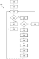
- FIG. 1 is a flow diagram of a method of determining position using a standalone GNSS receiver, in accordance with some embodiments.
- FIG. 2 is a schematic diagram of a standalone GNSS receiver in accordance with some embodiments.
- Global Navigation Satellite Systems are widely used for positioning, navigation, and timing.
- Global Navigation Satellite Systems include the United States' Global Positioning System (GPS), Russia's Global Navigation System (GLONASS), China's Beidou Navigation Satellite System (BDS), the European Union's Galileo Satellite Navigation System (Galileo), Japan's Quasi-Zenith Satellite System (QZSS), and the Indian Regional Navigation Satellite System (IRNSS).
- a GNSS receiver tracks signals from satellites of one, several or all of the global navigation systems listed above and determines, based on the received signals, pseudo-range and carrier phase measurements that are used to determine a GNSS receiver position. Signals and associated position measurements are degraded by systematic errors such as ionospheric effects, tropospheric delay, multipath, and so forth. Imprecision in satellite orbit and clock measurements that are calculated from real-time navigation messages also contribute to position uncertainty. Although ionospheric effects are mitigated by using dual-frequency measurements, and tropospheric delay is mitigated using meteorological data to model signal degradation, the errors resulting from ionospheric effects and tropospheric delays still accumulate up to several meters in position uncertainty in some instances. Thus Standard Point Positioning (SPP) is only accurate to several meter levels, even using dual-frequency GNSS receivers to mitigate ionospheric effects in some instances.
- SPP Standard Point Positioning
- Satellite Based Augmentation Systems such as Wide Area Augmentation System (WAAS), European Geostationary Navigation Overlay Service (EGNOS), and Multi-Functional Satellite Augmentation System (MSAS) provide orbit and clock corrections and further provide ionospheric grids for single frequency GNSS receivers to mitigate ionospheric effects.
- Global positioning using SBAS corrections routinely achieves meter-level accuracy, and sometimes achieves sub-meter level accuracy. Positioning accuracy of a standalone receiver improves positioning accuracy to meter level with SBAS corrections.
- SBAS involves real-time corrections that are free to a GNSS receiver user.
- PPP Precise Point Positioning
- the precise products used for real-time PPP are transmitted over geostationary satellite with L-Band signal, or over Internet.
- receivers that lack L-Band or Internet capability are unable to benefit from PPP.
- real-time precise products used for PPP are not free to a GNSS receiver user.
- a further drawback of PPP is the amount of convergence time to achieve a position determination. PPP convergence to centimeter-level accuracy takes longer than 10 minutes in some instances. Even with PPP ambiguity resolution (AR), the time to fix of PPP is still up to several minutes in some instances.
- AR PPP ambiguity resolution
- Real-time positioning methods circumvent the convergence delay concerns associated with PPP.
- Two principal methods of real-time positioning are Real-Time Kinematic (RTK) and Differential GPS (DGPS).
- DGPS uses pseudo-range measurements to determine position. Due to limitations on the resolution of measurements based on pseudo-range noise and multipath determination, DGPS positioning is limited to sub-meter level accuracy schemes.
- Real-Time Kinematic is a method of positioning that employs reference stations or reference receivers more quickly than PPP.
- RTK uses carrier phase measurements, which are much more accurate than pseudo-ranges, but sometimes provide ambiguous results.
- RTK positioning achieves centimeter level accuracy after the double-differenced ambiguities are fixed.
- AR ambiguity resolution
- RTK is the most widely used satellite positioning system when centimeter level accuracy is sought. Further, RTK methods provide greater accuracy than DGPS, down to centimeter-level accuracy, which is comparable to PPP accuracy. To achieve centimeter-level accuracy, and because of the convergence delay associated with PPP, RTK is more commonly used in terrestrial positioning. PPP is a predominant method of positioning in maritime applications, where reference receivers are not feasible.
- RTK positioning improves GNSS receiver accuracy by use of a reference station or reference receiver. Both real and virtual reference receiver are used in RTK positioning methodologies.
- a real reference receiver is a GNSS receiver tied to a single, fixed location that has been accurately measured or surveyed.
- Network RTK uses a receiver connected to a communication device such as an Internet connection and/or a radio transmitter. When a rover and a reference station are physically close, the error sources described above are common or correlated because the signals received by each of the rover and reference station passed through near-identical paths, with similar temperatures, thicknesses, ionization, refractive indices, and so forth.
- a communication device such as a radio or an Internet connection, is used to coordinate signals between a reference receiver and a portable GNSS receiver, or rover.
- the cost associated with setup and maintenance of a reference station which normally includes a high quality GNSS receiver, a surveying GNSS antenna, and of a communication device to distribute RTK correction data, is significantly more than a cost of a portable GNSS receiver.
- a Network RTK service To reduce the cost of RTK positioning, some users employ a Network RTK service. Network RTK service providers send real or virtual reference data to customers. Costs of Network RTK services are often still charged to a system user on, e.g., a per-minute basis.
- Hatch describes using carrier phase to smooth pseudo-range and reduce multipath and the noise of pseudo-range to improve positioning accuracy.
- Whitehead describes using internally generated differential corrections from an initial or initial epoch to get differenced position relative to an initial point, or a waypoint at which the corrections are computed for the initial epoch. The corrections are retained until the standalone GNSS receiver either returns to the start point or arrives at a different waypoint.
- the satellites visible to the standalone GNSS receiver (common view satellites) change during navigation, due to signal blockage or satellites traveling below the horizon. Further, satellite orbit and clock errors, ionospheric and tropospheric effects also change slowly.
- Ford describes using delta phase, Doppler and pseudo-range measurements in a Kalman filter, namely PDP Kalman filter, to improve position accuracy.
- PDP Kalman filter delta phases are used to estimate position errors of both current and previous epochs.
- a PDP Kalman filter of delta phase data is more precise than pseudo-range measurements, the Ford method provides smoother transitions between positions than point positioning.
- a disadvantage of the Ford method is that PDP Kalman filter uses continuous tracking between epochs to get delta phase measurements. Once a portable GNSS receiver loses tracking of a majority of satellites present at the start of tracking, the PDP filter has to be reset, causing a jump or discontinuity in the reported the standalone GNSS receiver position.
- a standalone GNSS receiver saves the coordinate determined at any epoch, as a reference coordinate.
- the reference coordinate is precisely surveyed, measured, or calculated.
- Pseudo-range and carrier phase measurements of the epoch are measured and saved as reference data associated with the reference coordinate at the reference epoch.
- the coordinate and measurements work as reference data for later epochs.
- the standalone GNSS receiver performs a RTK process using the current epoch measurements, the reference data, and the reference coordinate. When there is no cycle slip between the reference data and current epoch data, all ambiguities are zero and the position of current epoch is centimeter level accurate relative to the reference coordinate.
- ambiguity resolution is performed prior to the RTK process. Once the ambiguities are resolved, the coordinate of current epoch retains centimeter level accuracy relative to the reference coordinate. The coordinate and measurements of the ambiguity fixed epoch will be saved as new reference data for future positioning, old reference data will be discarded, and so forth.
- the current or original reference data is used for reporting position of the standalone GNSS receiver until an epoch when ambiguity resolution is successful.
- initial or original reference is replaced by new reference data associated with the epoch at which ambiguity resolution succeeded.
- the standalone GNSS receiver uses satellite signal to calculate comparison data used to determine a current coordinate.
- the comparison data and reference data are calculated in similar manners.
- the current coordinate are as accurate as the reference location.
- the coordinates associated with the epochs are all centimeter-level accurate relative to the first reference position.
- the accuracy with which the reference position is measured or determined is passed down to the current positions determined at later epochs.
- a centimeter-level accurate reference position provides centimeter-level accuracy for later epochs with resolved ambiguities.
- the coordinates of the later epochs are at least decimeter-level accurate.
- At least one embodiment of the present disclosure works similar to traditional RTK, but generates reference data within the standalone GNSS receiver at the start of navigation or positioning.
- the reference data for a later epoch, or a current epoch is not determine at a same epoch at a different coordinate, but at an initial epoch with respect to the later or current epoch.
- the present disclosure allows a standalone GNSS receiver to recover centimeter-level accurate positions once ambiguity resolution is successful after signal lock is reacquired. At least one embodiment of the present disclosure is capable of working in all scenarios where traditional RTK works, and provides comparable accuracy to a GNSS receiver used in conjunction with a reference station performing traditional RTK.
- a user is concerned with relative position.
- Some GNSS receivers are used for relative positioning in agricultural settings. For example, sowing, harvesting, fertilizing, and/or spraying vehicles rely on accurate relative positioning on subsequent passes through a field to avoid wasting product or harming crops.
- automated lawn mowers or Unmanned Aerial Vehicles (UAV) also rely on accurate relative positioning for subsequent passes through an area.
- Using traditional RTK methods to achieve high accurate relative positioning involves installing a reference receiver or using corrections from a network RTK service provider.
- a standalone GNSS receiver performs centimeter-level accurate relative positioning free of reliance on a reference receiver or a network RTK service provider.
- FIG. 1 is a flow diagram of a method 100 of determining position using a standalone GNSS receiver, according to some embodiments.
- Method 100 includes an operation 105 in which a standalone GNSS receiver observes a signal from a global navigation system satellite. Subsequent to observing for a signal, the standalone GNSS receiver receives an observed signal and records the signal to the standalone GNSS receiver storage medium. The signal, or reference signal, is received at a reference epoch.
- the standalone GNSS receiver generates a set of reference data based on the reference signal at the reference epoch.
- the reference data includes a coordinate position at the reference epoch, and reference observables such as a reference pseudo-range measurement and a reference carrier phase measurement.
- the reference position, or reference coordinate is precisely surveyed or estimated in order to help ensure that the reference position has centimeter-level accuracy.
- the reference position is determined using point positioning, or some other suitable method of reaching centimeter-level accurate positioning.
- the reference position is determined using a fixed survey point as a location reference.
- the reference data is saved to the standalone GNSS receiver storage medium for subsequent use in positioning at later epochs.
- a current epoch is an epoch at the time of a current measurement after the reference epoch.
- the current measurement at the current epoch includes a current pseudo-range and a current carrier phase.
- the method 100 includes an operation 115 , which the standalone GNSS receiver observes for another signal at a current epoch, an epoch after the reference epoch. At the current epoch, a signal is, or is not, received by the standalone GNSS receiver.
- the standalone GNSS receiver determines whether signal lock/signal continuity is preserved between the reference epoch and the current epoch.
- the method continues to operation 125 , wherein the standalone GNSS receiver generates a set of comparison data.
- the set of comparison data is generated based on the current signal at the current epoch and includes at least pseudo-range and carrier phase measurements.
- the standalone GNSS receiver determines a current position of the standalone GNSS receiver at the current epoch.
- the standalone GNSS receiver also stores the current signal, the set of comparison data, and the current coordinate/current position in a storage medium, and reports the current position to a user of the standalone GNSS receiver or a device communicatively connected to the standalone GNSS receiver.
- the method continues from operation 120 to operation 135 .
- the standalone GNSS receiver observes for a signal at a current epoch after the reference epoch. At the current epoch, a signal is, or is not, received by the standalone GNSS receiver.
- Method 100 continues in an operation 140 wherein the standalone GNSS receiver determines whether a signal has been received at the standalone GNSS receiver. When signal has not been observed, or when the position determination returns a negative result, or when signal lock has not been restored, or the signal continuity has not been restored, the method continues in an operation 145 , wherein the standalone GNSS receiver reports a current position of the standalone GNSS receiver at the current epoch. From operation 145 , the method returns to operation 115 . When, the signal has been observed, or signal lock has been restored, or the signal continuity has been restored, the method continues from operation 140 to operation 150 . In operation 150 , the standalone GNSS receiver performs an ambiguity resolution process according to the method described herein to resolve a position ambiguity.
- the method 100 includes operation 155 , wherein a real-time kinematic (RTK) process is performed according to methods described herein, to establish a correct current position coordinate.
- Method 100 includes an operation 160 , wherein based on the signal received at the current epoch, the standalone GNSS receiver generates a set of comparison data received at the current epoch.
- the set of comparison data includes pseudo-range and carrier phase measurements that are used to determine a GNSS receiver position.
- At least one preferred embodiment of the present disclosure instructs on how to use the reference data, the saved position and observables of the reference epoch, as a reference receiver for the standalone GNSS receiver in current epochs after a reference epoch.
- all positional or coordinate ambiguities are zero and the position of current epoch is centimeter level accurate relative to the reference coordinate. If signal lock is lost, or signal loss occurs, between the reference epoch and a current epoch, ambiguity resolution is performed to get high accurate relative position between the reference epoch and the current epoch.
- a standalone GNSS receiver is configured to measure and retain centimeter-level accuracy during operation. The accuracy of an original or reference position is retained or inherited for subsequent epochs, provided that signal continuity is retained, or regained after signal loss or discontinuity.
- position accuracy arises from double-differenced observable equations between measurements collected at the same epoch from two receivers at different locations.
- position accuracy arises from double-differenced observable equations between measurements collected at different epochs from a standalone receiver.
- Resolution of double-differenced ambiguities involves addressing and mitigating error sources such as ionospheric effects, tropospheric delay, and satellite orbit errors, even though positional inaccuracy related to these error sources is very small after double-differencing.
- measurements of reference receiver and GNSS receiver, or rover collect signals at the same time, eliminating satellite clock error as a source of positional error.
- satellite clock error is a factor to consider when performing position determination because signals are measured at different epochs.
- Multipath errors correlate between epochs, and are nearly completely eliminated by single differencing between epochs.
- Carrier phase noise is also a very small, less than 1 millimeter. Residuals causing by multipath and carrier noise are white noise and not accumulated over time. Their contribution to position error is millimeter level. In the present disclosure, they are treated as white noise.
- Error sources such as satellite orbit and clock errors, accumulate slowly, normally less than 1 millimeter per 1 second. After single differencing between epochs, which are sampled at least one time per second, the residuals are very small, less than 1 millimeter. However, positional error causing by satellite orbit and clock errors is accumulated over time. If they are not dealt with correctly, positioning error would be accumulated up to decimeter level after tens of minutes of time. So does the atmospheric effects. Ionospheric effects and tropospheric delay are satellite elevation depending, changes a little bit faster than orbit and clock errors.
- the residuals of double-differenced ionosphere and troposphere are very small, sometimes less than 1 millimeter within 1 second. But positional error causing by ionosphere and troposphere residuals is accumulated over time. If they are not dealt with correctly, positioning error would be accumulated up to decimeter level after tens of minutes of time. These residuals are addressed with in at least one embodiment of the present disclosure to provide high performance.
- error sources are mitigated according to the procedures and methods described below.
- Other means of mitigating error are also envisioned in the present disclosure and are known to practitioners of the art.
- Ionosphere effects are initially modeled with Klobuchar model before the amount of ionospheric error is estimated by a double-differenced residual.
- Geometric error in the form of tropospheric delay, is initially modeled with the Saastamoinen model, and the double-differenced residual is estimated together with double-differenced satellite orbit and clock residuals.
- At least one embodiment of the present disclosure works with continuous signal tracking between a current epoch and the reference epoch. At least one embodiment of the present disclosure works after interruptions in signal tracking between a current epoch and the reference epoch.
- the method described herein still recovers centimeter level accurate positioning once the receiver reacquires the signal and performs a RTK process between the epoch prior to signal lock, and the an epoch after signal reacquisition.
- at least one embodiment of the present disclosure works for any situation that employs other RTK.
- the states are estimated with a Kalman filter using double-differenced pseudo-range and carrier phase measurements.
- the state vector is shown in Table 1.
- the L1 measurements include GPS L1, GLONASS G1, BDS B1, Galileo E1, or QZSS L1.
- the L2 measurements include GPS L2, GLONASS G2, BDS B2, Galileo E5b, or QZSS L2.
- the L3 measurements include GPS L5, BDS B3, Galileo E5a, QZSS L5, or IRNSS L5.
- Position component X 1 Mandatory Position component Y 1
- Mandatory Position component Z 1 Mandatory Double-differenced ionosphere residuals Nsat-1
- Nsat-1 Mandatory Double-differenced geometry residuals
- Nsat-1 Mandatory Double-differenced L1 ambiguities Nsat-1 If L1 measurement available Double-differenced L2 ambiguities Nsat-1 If L2 measurement available Double-differenced L3 ambiguities Nsat-1 If L3 measurement available
- Position components X, Y and Z are modeled as random walk processes.
- Double-differenced ionosphere residuals are modeled as first-order Gauss-Markov processes.
- Double-differenced geometry residuals which include double-differenced troposphere residuals, double-differenced satellite orbit and clock residuals, are modeled as first-order Gauss-Markov process also.
- Double-differenced L1 ambiguity, L2 ambiguity, and L3 ambiguity, if available, are estimated as constants. Even a receiver can track triple-frequency signals, interference may lead to lose of track at any frequency. In the present invention, measurements from any frequency are used in Kalman Filter independently.
- n which works as rover
- all ambiguities are zero and ambiguity resolution is not performed.
- signal lock when signal lock is lost, or signal is interrupted, such as when a standalone GNSS receiver passes below a bridge, foliage, or in urban canyon, signal lock extends to multiple signal sources.
- signal loss is complete, and no signal is received by a standalone GNSS receiver.
- ambiguities are non-zero, and are float ambiguities. Centimeter-level accuracy with respect to a reference coordinate is restored after performing ambiguity resolution processes.
- the least-squares ambiguity decorrelation (LAMBDA) method of Teunissen described above is applied for ambiguity resolution.
- LAMBDA least-squares ambiguity decorrelation
- Preferred embodiments of the present disclosure are usable in applications in which accurate relative positioning is sought.
- precise agriculture applications such as sowing, harvesting, fertilizing or spraying vehicles
- pass to pass accuracy is important.
- These vehicles do not need a high accurate initial position, but high accurate relative position to the initial position. This is also the case for lawn mowers or some Unmanned Aerial Vehicles (UAV).
- UAV Unmanned Aerial Vehicles
- To achieve high accurate relative positioning currently most users have to setup a reference receiver or use corrections from a network RTK service provider.
- At least one embodiment of this disclosure helps to reduce the cost and complexity of these applications, as only a standalone GNSS receiver is used.
- Reference receiver and communication device which is used in other RTK to receive reference data are both eliminated in at least one embodiment.
- FIG. 2 is a block diagram of a GNSS receiver 200 , in accordance with some embodiments.
- Methods described herein of position determination, in accordance with one or more embodiments, are implementable, for example, using GNSS receiver 200 , in accordance with some embodiments.
- GNSS receiver 200 is a computing device including a hardware processor 202 and a non-transitory, computer-readable storage medium 204 .
- Storage medium 204 is encoded with, i.e., stores, computer program code 206 , i.e., a set of executable instructions.
- Execution of instructions 206 by hardware processor 202 represents (at least in part) an the equations provided above with regard to performing positioning, and instructions related to operating receiving and sending information using the hardware components of the standalone GNSS receiver.
- the instructions disclosed here are configured to enable the standalone GNSS receiver to perform some or all of the methods described herein.
- Processor 202 is electrically coupled to computer-readable storage medium 204 via a bus 208 .
- Processor 202 is also electrically coupled to an I/O interface 210 by bus 208 .
- a communication interface 212 is also electrically connected to processor 202 via bus 208 .
- Communication interface 212 is connected to a network 214 , so that processor 202 and computer-readable storage medium 204 are capable of connecting to external elements via network 214 .
- Processor 202 is configured to execute computer program code 206 encoded in computer-readable storage medium 204 in order to cause GNSS receiver 200 to be usable for performing a portion or all of the noted processes and/or methods.
- processor 202 is a central processing unit (CPU), a multi-processor, a distributed processing system, an application specific integrated circuit (ASIC), and/or a suitable processing unit.
- CPU central processing unit
- ASIC application specific integrated circuit
- computer-readable storage medium 204 is an electronic, magnetic, optical, electromagnetic, infrared, and/or a semiconductor system (or apparatus or device).
- computer-readable storage medium 204 includes a semiconductor or solid-state memory, a magnetic tape, a removable computer diskette, a random access memory (RAM), a read-only memory (ROM), a rigid magnetic disk, and/or an optical disk.
- computer-readable storage medium 204 includes a compact disk-read only memory (CD-ROM), a compact disk-read/write (CD-R/W), and/or a digital video disc (DVD).
- storage medium 204 stores computer program code 206 configured to cause GNSS receiver 200 to be usable for performing a portion or all of the noted processes and/or methods. In one or more embodiments, storage medium 204 also stores information which facilitates performing a portion or all of the noted processes and/or methods. In one or more embodiments, storage medium 204 stores reference data 207 for use in comparing with other signals received at communication interface 212 .
- GNSS receiver 200 includes I/O interface 210 .
- I/O interface 210 is coupled to external circuitry.
- I/O interface 210 includes a keyboard, keypad, mouse, trackball, trackpad, touchscreen, and/or cursor direction keys for communicating information and commands to processor 202 .
- GNSS receiver 200 also includes communication interface 212 coupled to processor 202 .
- Communication interface 212 allows GNSS receiver 200 to communicate with a network 214 , such as a global positioning satellite, to which one or more other navigation systems are connected.
- Communication interface 212 includes one or more of GPS, GLONASS, BDS, Galileo, QZSS, IRNSS, and so forth. In one or more embodiments, a portion or all of noted processes and/or methods, is implemented in two or more GNSS receivers 200 .
- GNSS receiver 200 is configured to receive information through I/O interface 210 .
- the information received through I/O interface 210 includes one or more of instructions, data, design rules, libraries of standard cells, and/or other parameters for processing by processor 202 .
- the information is transferred to processor 202 via bus 208 .
- GNSS receiver 200 is configured to receive information related to a UI through I/O interface 210 .
- the information is stored in computer-readable medium 204 as user interface (UI) 242 .
- UI user interface
- a portion or all of the noted processes and/or methods is implemented as a standalone software application for execution by a processor. In some embodiments, a portion or all of the noted processes and/or methods is implemented as a software application that is a part of an additional software application. In some embodiments, a portion or all of the noted processes and/or methods is implemented as a plug-in to a software application. In some embodiments, at least one of the noted processes and/or methods is implemented as a software application that is a portion of a global navigation receiver.
- the processes are realized as functions of a program stored in a non-transitory computer readable recording medium.
- a non-transitory computer readable recording medium include, but are not limited to, external/removable and/or internal/built-in storage or memory unit, e.g., one or more of an optical disk, such as a DVD, a magnetic disk, such as a hard disk, a semiconductor memory, such as a ROM, a RAM, a memory card, and the like.
Landscapes
- Engineering & Computer Science (AREA)
- Radar, Positioning & Navigation (AREA)
- Remote Sensing (AREA)
- Computer Networks & Wireless Communication (AREA)
- Physics & Mathematics (AREA)
- General Physics & Mathematics (AREA)
- Position Fixing By Use Of Radio Waves (AREA)
Abstract
Description
where: Pm,k i is pseudo-range measurement of frequency k for satellite i at epoch m;
ρm i is geometric distance between satellite i and antenna phase center at epoch m;
c is speed of light in vacuum;
dTr,m is receiver clock error at epoch m;
dts,m i is satellite i clock error at epoch m;
Orbm i is satellite i orbit error at epoch m;
Tropm i is satellite i troposphere error at epoch m;
Ionom i is satellite i ionosphere error at epoch m;
fl 2 and fk 2 are the square of frequency Ll and Lk, respectively, k may be 1, 2 or 3;
νk i is multipath and noise of frequency k pseudo-range;
Φm,k i is carrier phase measurement of frequency k for satellite i at epoch m;
λk is wavelength of frequency k; Nm,k i is integer ambiguity of frequency k for satellite i at epoch m; and
εk i is multipath and noise of frequency k carrier phase.
where n indicates epoch n. n is not necessary to be m+l. n is any epoch after epoch m.
where:
Δ is a single difference operator between epoch m and n;
∇ is a single difference operator between satellite i and j;
∇ΔPmn,k ij is double-differenced pseudo-range measurement of frequency k;
∇Δρmn ij is double-differenced geometric distance;
∇Δdts,mn ij is double-differenced satellite clock residual;
∇ΔOrbmn ij is double-differenced satellite orbit residual;
∇ΔTropmn ij is double-differenced troposphere residual;
∇ΔIonomn ij is double-differenced ionosphere residual;
∇Δνk ij is double-differenced multipath residual and noise of frequency k pseudo-range;
∇ΔΦmn,k ij is double-differenced carrier phase measurement of frequency k;
∇ΔNmn,k ij is double-differenced integer ambiguity of frequency k; and
∇Δεk ij is double-differenced multipath residual and noise of frequency k carrier phase.
∇Δd geo ij=∇ΔOrbmn ij −c·∇Δdt s,mn ij+∇ΔTropmn ij (Equation 7)
| TABLE 1 |
| Kalman Filter State Vector |
| States | Dimension | Notes |
| Position component X | 1 | Mandatory |
| Position component Y | 1 | Mandatory |
| Position component Z | 1 | Mandatory |
| Double-differenced ionosphere residuals | Nsat-1 | Mandatory |
| Double-differenced geometry residuals | Nsat-1 | Mandatory |
| Double-differenced L1 ambiguities | Nsat-1 | If L1 measurement |
| available | ||
| Double-differenced L2 ambiguities | Nsat-1 | If L2 measurement |
| available | ||
| Double-differenced L3 ambiguities | Nsat-1 | If L3 measurement |
| available | ||
Claims (20)
Priority Applications (2)
| Application Number | Priority Date | Filing Date | Title |
|---|---|---|---|
| US16/134,664 US10830902B2 (en) | 2018-06-21 | 2018-09-18 | Real-time kinematic using standalone global navigation satellite system receiver |
| US17/089,779 US11415705B2 (en) | 2018-06-21 | 2020-11-05 | Method, apparatus for carrier-phase cycle-slip detection and repair |
Applications Claiming Priority (2)
| Application Number | Priority Date | Filing Date | Title |
|---|---|---|---|
| US201862687988P | 2018-06-21 | 2018-06-21 | |
| US16/134,664 US10830902B2 (en) | 2018-06-21 | 2018-09-18 | Real-time kinematic using standalone global navigation satellite system receiver |
Related Child Applications (1)
| Application Number | Title | Priority Date | Filing Date |
|---|---|---|---|
| US17/089,779 Continuation US11415705B2 (en) | 2018-06-21 | 2020-11-05 | Method, apparatus for carrier-phase cycle-slip detection and repair |
Publications (2)
| Publication Number | Publication Date |
|---|---|
| US20190391274A1 US20190391274A1 (en) | 2019-12-26 |
| US10830902B2 true US10830902B2 (en) | 2020-11-10 |
Family
ID=68981675
Family Applications (2)
| Application Number | Title | Priority Date | Filing Date |
|---|---|---|---|
| US16/134,664 Active 2039-03-14 US10830902B2 (en) | 2018-06-21 | 2018-09-18 | Real-time kinematic using standalone global navigation satellite system receiver |
| US17/089,779 Active 2038-12-16 US11415705B2 (en) | 2018-06-21 | 2020-11-05 | Method, apparatus for carrier-phase cycle-slip detection and repair |
Family Applications After (1)
| Application Number | Title | Priority Date | Filing Date |
|---|---|---|---|
| US17/089,779 Active 2038-12-16 US11415705B2 (en) | 2018-06-21 | 2020-11-05 | Method, apparatus for carrier-phase cycle-slip detection and repair |
Country Status (1)
| Country | Link |
|---|---|
| US (2) | US10830902B2 (en) |
Cited By (1)
| Publication number | Priority date | Publication date | Assignee | Title |
|---|---|---|---|---|
| US12436292B2 (en) * | 2020-04-21 | 2025-10-07 | Javad Gnss, Inc. | Enhanced real-time kinematic (RTK) |
Families Citing this family (11)
| Publication number | Priority date | Publication date | Assignee | Title |
|---|---|---|---|---|
| CN111679307B (en) * | 2020-07-14 | 2023-08-25 | 金华航大北斗应用技术有限公司 | Satellite positioning signal resolving method and device |
| US11675091B2 (en) | 2020-08-20 | 2023-06-13 | Qualcomm Incorporated | RTK GNSS positioning without base stations |
| WO2022107941A1 (en) * | 2020-11-22 | 2022-05-27 | 이상주 | Rtk group positioning method using temporary reference terminal device |
| US11914049B2 (en) * | 2021-02-04 | 2024-02-27 | Qualcomm Incorporated | Methods and apparatus for improving carrier phase detection in satellite positioning system signals |
| WO2022192870A1 (en) * | 2021-03-08 | 2022-09-15 | Microchip Technology Incorporated | Scalable common view time transfer and related apparatuses and methods |
| US12429604B2 (en) * | 2022-03-18 | 2025-09-30 | Qualcomm Incorporated | Methods and apparatus for carrier phase continuity in satellite positioning system signals |
| CN115826003A (en) * | 2022-07-13 | 2023-03-21 | 辽宁工程技术大学 | A three-frequency cycle-slip detection method for BDS based on Doppler integration |
| CN115291246B (en) * | 2022-07-13 | 2026-01-06 | 桂林电子科技大学 | A method for detecting cycle slips in discontinuous epochs |
| CN115144882B (en) * | 2022-07-15 | 2024-05-07 | 中国科学院国家授时中心 | A precise single-point positioning method and system based on GNSS and 5G combination |
| EP4379425A1 (en) * | 2022-12-02 | 2024-06-05 | Trimble Inc. | Synthetic carrier phase observable generating methods and systems for use in forming time-differenced navigation satellite system observables |
| US20250093518A1 (en) * | 2023-09-15 | 2025-03-20 | Saudi Arabian Oil Company | Method and system for managing positioning signals using error data |
Citations (6)
| Publication number | Priority date | Publication date | Assignee | Title |
|---|---|---|---|---|
| US5471217A (en) | 1993-02-01 | 1995-11-28 | Magnavox Electronic Systems Company | Method and apparatus for smoothing code measurements in a global positioning system receiver |
| US6397147B1 (en) | 2000-06-06 | 2002-05-28 | Csi Wireless Inc. | Relative GPS positioning using a single GPS receiver with internally generated differential correction terms |
| US6664923B1 (en) | 2002-09-24 | 2003-12-16 | Novatel, Inc. | Position and velocity Kalman filter for use with global navigation satelite system receivers |
| US20140113608A1 (en) * | 2010-04-12 | 2014-04-24 | Nokia Corporation | Periodic Assistance Data Flow Control |
| US20150301190A1 (en) * | 2011-09-16 | 2015-10-22 | Trimble Navigation Limited | GNSS Signal Processing Methods and Apparatus |
| US20200116873A1 (en) * | 2017-06-09 | 2020-04-16 | Panasonic Intellectual Property Management Co., Ltd. | Positioning method and positioning terminal |
Family Cites Families (6)
| Publication number | Priority date | Publication date | Assignee | Title |
|---|---|---|---|---|
| US7162367B2 (en) * | 1999-11-29 | 2007-01-09 | American Gnc Corporation | Self-contained/interruption-free positioning method and system thereof |
| US6496778B1 (en) * | 2000-09-14 | 2002-12-17 | American Gnc Corporation | Real-time integrated vehicle positioning method and system with differential GPS |
| CN106405592B (en) * | 2016-12-09 | 2019-05-17 | 惠州市组合科技有限公司 | Vehicle-mounted Beidou carrier phase cycle slips detection and restorative procedure and system |
| CN107102346B (en) * | 2017-06-08 | 2020-02-07 | 中国电子科技集团公司第五十四研究所 | Multi-antenna attitude measurement method based on Beidou system |
| CN108169774B (en) * | 2017-12-26 | 2021-09-10 | 北方信息控制研究院集团有限公司 | Multimode GNSS single-frequency cycle slip detection and repair method supporting RTPPP and RTK |
| CN108873034A (en) * | 2018-03-30 | 2018-11-23 | 广州海格通信集团股份有限公司 | A kind of implementation method of inertial navigation subcarrier ambiguity resolution |
-
2018
- 2018-09-18 US US16/134,664 patent/US10830902B2/en active Active
-
2020
- 2020-11-05 US US17/089,779 patent/US11415705B2/en active Active
Patent Citations (6)
| Publication number | Priority date | Publication date | Assignee | Title |
|---|---|---|---|---|
| US5471217A (en) | 1993-02-01 | 1995-11-28 | Magnavox Electronic Systems Company | Method and apparatus for smoothing code measurements in a global positioning system receiver |
| US6397147B1 (en) | 2000-06-06 | 2002-05-28 | Csi Wireless Inc. | Relative GPS positioning using a single GPS receiver with internally generated differential correction terms |
| US6664923B1 (en) | 2002-09-24 | 2003-12-16 | Novatel, Inc. | Position and velocity Kalman filter for use with global navigation satelite system receivers |
| US20140113608A1 (en) * | 2010-04-12 | 2014-04-24 | Nokia Corporation | Periodic Assistance Data Flow Control |
| US20150301190A1 (en) * | 2011-09-16 | 2015-10-22 | Trimble Navigation Limited | GNSS Signal Processing Methods and Apparatus |
| US20200116873A1 (en) * | 2017-06-09 | 2020-04-16 | Panasonic Intellectual Property Management Co., Ltd. | Positioning method and positioning terminal |
Non-Patent Citations (1)
| Title |
|---|
| Teunissen, P.J.G., "The least-squares ambiguity decorrelation adjustment: a method for fast GPS integer ambiguity estimation", J. Geodesy. 1995, vol. 70, pp. 65-82. |
Cited By (1)
| Publication number | Priority date | Publication date | Assignee | Title |
|---|---|---|---|---|
| US12436292B2 (en) * | 2020-04-21 | 2025-10-07 | Javad Gnss, Inc. | Enhanced real-time kinematic (RTK) |
Also Published As
| Publication number | Publication date |
|---|---|
| US11415705B2 (en) | 2022-08-16 |
| US20190391274A1 (en) | 2019-12-26 |
| US20210373178A1 (en) | 2021-12-02 |
Similar Documents
| Publication | Publication Date | Title |
|---|---|---|
| US11415705B2 (en) | Method, apparatus for carrier-phase cycle-slip detection and repair | |
| JP7122023B2 (en) | High-speed precision positioning method and system | |
| US11506796B2 (en) | Method, apparatus and mobile device for extending real-time kinematic positioning during reference data outage | |
| US7982667B2 (en) | Post-processed accuracy prediction for GNSS positioning | |
| US8174437B2 (en) | System and method for augmenting DGNSS with internally-generated differential correction | |
| EP3314303B1 (en) | Satellite navigation receiver and method for switching between real-time kinematic mode and relative positioning mode | |
| US9671501B2 (en) | Global navigation satellite systems (GNSS) positioning using precise satellite data | |
| EP2044457B1 (en) | A method for increasing the reliability of position information when transitioning from a regional, wide-area, or global carrier-phase differential navigation (wadgps) to a local real-time kinematic (rtk) navigation system | |
| US9958550B2 (en) | Navigation satellite system positioning involving the generation of receiver-specific or receiver-type-specific correction information | |
| US8188913B2 (en) | Method for a global satellite navigation system | |
| US20120286991A1 (en) | GNSS Signal Processing with Regional Augmentation Positioning | |
| US11125890B2 (en) | Advanced navigation satellite system positioning method and system using seeding information | |
| US20220011443A1 (en) | Method and System for Recreating Unavailable GNSS Measurements | |
| Rabbou et al. | Precise Point Positioning using Multi-Constellation GNSS Observations for Kinematic Applications. | |
| US12313751B2 (en) | System and method for compensating for scintillation and for facilitation of long-baseline RTK | |
| CN110068843A (en) | Satellite positioning receiver, method and apparatus | |
| Feng et al. | Wide area real time kinematic decimetre positioning with multiple carrier GNSS signals | |
| Liu et al. | Assessing partial ambiguity resolution and WZTD-constraint multi-frequency RTK in an urban environment using new BDS signals | |
| CN116879936A (en) | INS-assisted Beidou three-frequency ambiguity initialization method and system between dynamic targets | |
| Kondratiuk et al. | Testing static and kinematic modes of precise point positioning service in Ukraine | |
| WO2022201606A1 (en) | Position measurement apparatus, position measurement program, and position measurement method | |
| Gaglione et al. | Robust Kalman Filter applied to GNSS positioning in harsh environment | |
| Basile et al. | Multi-Frequency Precise Point Positioning using GPS and Galileo data with smoothed ionospheric corrections | |
| Rabbou et al. | Performance analysis of GPS/Galileo PPP model for static and kinematic applications | |
| Song et al. | A real-time moving baseline RTK framework for cooperative positioning of UAVs and ground vehicles |
Legal Events
| Date | Code | Title | Description |
|---|---|---|---|
| AS | Assignment |
Owner name: UNICORE COMMUNICATIONS TECHNOLOGY CORPORATION, CAL Free format text: ASSIGNMENT OF ASSIGNORS INTEREST;ASSIGNORS:CHEN, KONGZHE;HU, GANG;HUANG, LEI;REEL/FRAME:047103/0573 Effective date: 20180903 Owner name: UNICORE COMMUNICATIONS TECHNOLOGY CORPORATION, CALIFORNIA Free format text: ASSIGNMENT OF ASSIGNORS INTEREST;ASSIGNORS:CHEN, KONGZHE;HU, GANG;HUANG, LEI;REEL/FRAME:047103/0573 Effective date: 20180903 |
|
| FEPP | Fee payment procedure |
Free format text: ENTITY STATUS SET TO UNDISCOUNTED (ORIGINAL EVENT CODE: BIG.); ENTITY STATUS OF PATENT OWNER: SMALL ENTITY |
|
| FEPP | Fee payment procedure |
Free format text: ENTITY STATUS SET TO SMALL (ORIGINAL EVENT CODE: SMAL); ENTITY STATUS OF PATENT OWNER: SMALL ENTITY |
|
| STPP | Information on status: patent application and granting procedure in general |
Free format text: NON FINAL ACTION MAILED |
|
| AS | Assignment |
Owner name: UNICORE COMMUNICATIONS, INC., CHINA Free format text: ASSIGNMENT OF ASSIGNORS INTEREST;ASSIGNOR:UNICORE COMMUNICATIONS TECHNOLOGY CORPORATION;REEL/FRAME:052766/0461 Effective date: 20200422 |
|
| STPP | Information on status: patent application and granting procedure in general |
Free format text: RESPONSE TO NON-FINAL OFFICE ACTION ENTERED AND FORWARDED TO EXAMINER |
|
| STPP | Information on status: patent application and granting procedure in general |
Free format text: PUBLICATIONS -- ISSUE FEE PAYMENT RECEIVED |
|
| STCF | Information on status: patent grant |
Free format text: PATENTED CASE |
|
| MAFP | Maintenance fee payment |
Free format text: PAYMENT OF MAINTENANCE FEE, 4TH YR, SMALL ENTITY (ORIGINAL EVENT CODE: M2551); ENTITY STATUS OF PATENT OWNER: SMALL ENTITY Year of fee payment: 4 |