US10828508B2 - Detecting collision - Google Patents
Detecting collision Download PDFInfo
- Publication number
- US10828508B2 US10828508B2 US16/293,174 US201916293174A US10828508B2 US 10828508 B2 US10828508 B2 US 10828508B2 US 201916293174 A US201916293174 A US 201916293174A US 10828508 B2 US10828508 B2 US 10828508B2
- Authority
- US
- United States
- Prior art keywords
- model
- boundary
- component
- spatial position
- detection
- Prior art date
- Legal status (The legal status is an assumption and is not a legal conclusion. Google has not performed a legal analysis and makes no representation as to the accuracy of the status listed.)
- Active
Links
- 238000000034 method Methods 0.000 claims abstract description 155
- 238000001514 detection method Methods 0.000 claims abstract description 139
- 230000008569 process Effects 0.000 claims abstract description 109
- 238000004088 simulation Methods 0.000 claims description 43
- 238000001959 radiotherapy Methods 0.000 claims description 33
- 230000004044 response Effects 0.000 claims description 9
- 230000000712 assembly Effects 0.000 claims description 4
- 238000000429 assembly Methods 0.000 claims description 4
- 230000001960 triggered effect Effects 0.000 claims description 2
- 238000010586 diagram Methods 0.000 description 14
- 238000011161 development Methods 0.000 description 5
- 230000018109 developmental process Effects 0.000 description 5
- 238000011897 real-time detection Methods 0.000 description 5
- 230000015654 memory Effects 0.000 description 4
- 230000037237 body shape Effects 0.000 description 2
- 238000004590 computer program Methods 0.000 description 2
- 238000002595 magnetic resonance imaging Methods 0.000 description 2
- 238000012986 modification Methods 0.000 description 2
- 230000004048 modification Effects 0.000 description 2
- 238000002600 positron emission tomography Methods 0.000 description 2
- 210000001015 abdomen Anatomy 0.000 description 1
- 230000004075 alteration Effects 0.000 description 1
- 201000011510 cancer Diseases 0.000 description 1
- 238000002591 computed tomography Methods 0.000 description 1
- 239000000686 essence Substances 0.000 description 1
- 230000006870 function Effects 0.000 description 1
- 239000007787 solid Substances 0.000 description 1
- 238000002604 ultrasonography Methods 0.000 description 1
Images


Classifications
-
- A—HUMAN NECESSITIES
- A61—MEDICAL OR VETERINARY SCIENCE; HYGIENE
- A61N—ELECTROTHERAPY; MAGNETOTHERAPY; RADIATION THERAPY; ULTRASOUND THERAPY
- A61N5/00—Radiation therapy
- A61N5/10—X-ray therapy; Gamma-ray therapy; Particle-irradiation therapy
- A61N5/103—Treatment planning systems
- A61N5/1037—Treatment planning systems taking into account the movement of the target, e.g. 4D-image based planning
-
- A—HUMAN NECESSITIES
- A61—MEDICAL OR VETERINARY SCIENCE; HYGIENE
- A61N—ELECTROTHERAPY; MAGNETOTHERAPY; RADIATION THERAPY; ULTRASOUND THERAPY
- A61N5/00—Radiation therapy
- A61N5/10—X-ray therapy; Gamma-ray therapy; Particle-irradiation therapy
- A61N5/1048—Monitoring, verifying, controlling systems and methods
-
- A—HUMAN NECESSITIES
- A61—MEDICAL OR VETERINARY SCIENCE; HYGIENE
- A61N—ELECTROTHERAPY; MAGNETOTHERAPY; RADIATION THERAPY; ULTRASOUND THERAPY
- A61N5/00—Radiation therapy
- A61N5/10—X-ray therapy; Gamma-ray therapy; Particle-irradiation therapy
- A61N5/103—Treatment planning systems
- A61N5/1039—Treatment planning systems using functional images, e.g. PET or MRI
-
- A—HUMAN NECESSITIES
- A61—MEDICAL OR VETERINARY SCIENCE; HYGIENE
- A61N—ELECTROTHERAPY; MAGNETOTHERAPY; RADIATION THERAPY; ULTRASOUND THERAPY
- A61N5/00—Radiation therapy
- A61N5/10—X-ray therapy; Gamma-ray therapy; Particle-irradiation therapy
- A61N2005/1092—Details
-
- A—HUMAN NECESSITIES
- A61—MEDICAL OR VETERINARY SCIENCE; HYGIENE
- A61N—ELECTROTHERAPY; MAGNETOTHERAPY; RADIATION THERAPY; ULTRASOUND THERAPY
- A61N5/00—Radiation therapy
- A61N5/10—X-ray therapy; Gamma-ray therapy; Particle-irradiation therapy
- A61N5/103—Treatment planning systems
-
- A—HUMAN NECESSITIES
- A61—MEDICAL OR VETERINARY SCIENCE; HYGIENE
- A61N—ELECTROTHERAPY; MAGNETOTHERAPY; RADIATION THERAPY; ULTRASOUND THERAPY
- A61N5/00—Radiation therapy
- A61N5/10—X-ray therapy; Gamma-ray therapy; Particle-irradiation therapy
- A61N5/1042—X-ray therapy; Gamma-ray therapy; Particle-irradiation therapy with spatial modulation of the radiation beam within the treatment head
Definitions
- Medical linear accelerator systems are mainly used to perform radiotherapy treatment for malignant tumors.
- many components of a medical linear accelerator system such as a treatment bed, a treatment head and a gantry, may move.
- NMS NEUSOFT MEDICAL SYSTEMS CO., LTD.
- NMS NEUSOFT MEDICAL SYSTEMS CO., LTD.
- CT Magnetic Resonance Imaging
- PET Positron Emission Tomography
- LINAC Linear Accelerator
- biochemistry analyser Currently, NMS' products are exported to over 60 countries and regions around the globe, serving more than 5,000 renowned customers.
- NMS has been committed to the study of avoiding secondary potential harm caused by excessive X-ray irradiation to the subject during the CT scanning process.
- the present disclosure provides methods, devices, and systems for detecting collision in a target system including at least one movable component, e.g., a medical linear accelerator system, which can determine whether a collision between components will occur by simulating spatial positions of the components without using a collision-sensing apparatus.
- a target system including at least one movable component, e.g., a medical linear accelerator system, which can determine whether a collision between components will occur by simulating spatial positions of the components without using a collision-sensing apparatus.
- one innovative aspect of the subject matter described in this specification can be embodied in methods that include the actions of detecting collision for a target system including at least one movable component, including: obtaining a first model by performing modelling based on an exterior shape of a first component in the target system, the first component being a movable component; obtaining a second model by performing modelling based on an exterior shape of a second component in the target system, the second component being different from the first component; determining a spatial position of the first model and a spatial position of the second model according to a movement process of the first component at each of detection timings; and for each of the detection timings, determining whether the first component collides with the second component according to the spatial position of the first model, the spatial position of the second model, and a collision condition.
- inventions of this aspect include corresponding computer systems, apparatus, and computer programs recorded on one or more computer storage devices, each configured to perform the actions of the methods.
- a system of one or more computers to be configured to perform particular operations or actions means that the system has installed on it software, firmware, hardware, or a combination of them that in operation cause the system to perform the operations or actions.
- one or more computer programs to be configured to perform particular operations or actions means that the one or more programs include instructions that, when executed by data processing apparatus, cause the apparatus to perform the operations or actions.
- determining whether the first component collides with the second component can include: determining whether the spatial position of the first model and the spatial position of the second model satisfy the collision condition, and the collision condition can refer to that the first model and the second model contact with each other.
- the movement process of the first component is pre-simulated before a real movement process of the first component.
- the movement process of the first component is simulated approximately synchronously with a real movement process of the first component.
- the actions further include: for each of the detection timings in the movement process, determining the spatial position of the first model and the spatial position of the second model at a detection period subsequent to the detection timing; determining whether the first model and the second model contact with each other at the detection period in a simulation based on the spatial position of the first model and the spatial position of the second model at the detection period; and determining whether the first component will collide with the second component at the detection period in the real movement process based on a result of determining whether the first model and the second model contact with each other at the detection period in the simulation.
- the actions can further include: in response to determining that the first component will collide with the second component at the detection period in the real movement process, terminating a corresponding operation plan of the target system by at least one of stopping each moving component in the target system or prompting safety warning information to a user.
- the actions further include: setting a first rigidbody assembly and a first collider assembly for the first model; and setting a second rigidbody assembly and a second collider assembly for the second model.
- determining whether the first component collides with the second component includes: setting a first boundary for the first model, where, there is a first boundary gap between the first boundary and a boundary of the first model, and a value of the first boundary gap is equal to or greater than zero; setting a second boundary for the second model, where, there is a second boundary gap between the second boundary and a boundary of the second model, and a value of the second boundary gap is equal to or greater than zero; for each of the detection timings, determining whether a boundary overlapping occurs between the first boundary and the second boundary according to the spatial position of the first model and the spatial position of the second model; and in response to determining that the boundary overlapping occurs between the first boundary and the second boundary, determining that the first component collides with the second component.
- a range enclosed by the first boundary when the value of the first boundary gap is equal to zero, a range enclosed by the first boundary is consistent with the exterior shape of the first model; when the value of the first boundary gap is greater than zero, a range enclosed by the first boundary includes the first model; when the value of the second boundary gap is equal to zero, a range enclosed by the second boundary is consistent with the exterior shape of the second model; and when the value of the second boundary gap is greater than zero, a range enclosed by the second boundary includes the second model.
- determining whether a boundary overlapping occurs between the first boundary and the second boundary includes: determining a spatial position of the first boundary based on the spatial position of the first model and the value of the first boundary gap; determining a spatial position of the second boundary based on the spatial position of the second model and the value of the second boundary gap; and determining whether the boundary overlapping occurs between the first boundary and the second boundary based on the spatial position of the first boundary and the spatial position of the second boundary.
- the boundary overlapping can include any one of: a point contact, a line contact, a surface contact, and a block contact.
- the target system can include a medical linear accelerator system
- the first component can include a treatment head of the medical linear accelerator system
- the second component can include a treatment bed of the medical linear accelerator system.
- Determining the spatial position of the first model and the spatial position of the second model can include: obtaining a radiotherapy treatment plan of a subject to be treated; and determining the spatial position of the first model and the spatial position of the second model according to the movement process of the first component recorded in the radiotherapy treatment plan at each of the detection timings.
- the actions further include: during a process of performing treatment for the subject according to the radiotherapy treatment plan, obtaining a third model by performing modelling based on an exterior shape of the subject.
- the actions can further include: determining a spatial position of the third model at each of the detection timings; and for each of the detection timings, determining whether the first component collides with the subject according to the spatial position of the first model, the spatial position of the third model and the collision condition.
- obtaining the third model by performing modelling based on the exterior shape of the subject includes: obtaining three-dimension (3D) image data of the subject with a 3D camera; and obtaining the third model by performing the modelling based on the three-dimension image data of the subject.
- the actions can further include: at each of the detection timings, determining a spatial position of the third model based on the movement process of the first component; and adjusting the spatial position of the third model based on dynamic 3D image data of the subject real-time transmitted from the 3D camera.
- determining whether the first component collides with the subject includes: setting a first boundary for the first model, where, there is a first boundary gap between the first boundary and a boundary of the first model, and a value of the first boundary gap is equal to or greater than zero; setting a third boundary for the subject, where, there is a third boundary gap between the third boundary and a boundary of the third model, and a value of the third boundary gap is equal to or greater than zero; for each of the detection timings, determining whether a boundary overlapping occurs between the first boundary and the third boundary according to the spatial position of the first model and the spatial position of the third model; and in response to determining that the boundary overlapping occurs between the first boundary and the third boundary, determining that the first component collides with the subject.
- the boundary overlapping can include any one of: a point contact, a line contact, a surface contact, and a block contact.
- the movement process of the first component is simulated approximately synchronously with a real movement process of the first component
- the actions can further include: for each of the detection timings in the movement process, determining the spatial position of the first model at a detection period subsequent to the detection timing and the spatial position of the third model at the detection timing; determining whether the first model and the third model contact with each other at the detection period in a simulation based on the spatial position of the first model at the detection period and the spatial position of the third model at the detection timing; and determining whether the first component will collide with the third component at the detection period in the real movement process based on a result of determining whether the first model and the third model contact with each other at the detection period in the simulation.
- FIG. 1 is a flowchart illustrating a process of a method of detecting collision according to an example of the present disclosure.
- FIG. 2 is a flowchart illustrating a process of a method of detecting collision according to another example of the present disclosure.
- FIG. 3 is a flowchart illustrating a modelling process according to an example of the present disclosure.
- FIG. 4 is a block diagram illustrating a pre-simulation process according to an example of the present disclosure.
- FIG. 5 is a block diagram illustrating a real-time detection process according to an example of the present disclosure.
- FIG. 6 is a flowchart illustrating a process of a method of detecting collision according to still another example of the present disclosure.
- FIG. 7A is a schematic diagram illustrating a first boundary gap according to an example of the present disclosure.
- FIG. 7B is a schematic diagram illustrating a second boundary gap according to an example of the present disclosure.
- FIG. 8A is a schematic diagram illustrating a point contact according to an example of the present disclosure.
- FIG. 8B is a schematic diagram illustrating a line contact or a surface contact according an example of the present disclosure.
- FIG. 8C is a schematic diagram illustrating a block contact according to an example of the present disclosure.
- FIG. 9 is a schematic diagram illustrating a third boundary gap according to an example of the present disclosure.
- FIG. 10 is a schematic diagram illustrating a hardware structure of an apparatus for detecting collision according to an example of the present disclosure.
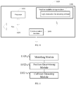
- FIG. 11 is a structural diagram illustrating function modules of logic instructions for detecting collision according to an example of the present disclosure.
- the system may have a plurality of moving components, such as a treatment head, a treatment bed, and a gantry. These components may collide with each other during a movement process, and thus the medical linear accelerator system may be damaged and the safety of a user (for example, a doctor or an operator) and a subject (for example, a patient) may also be harmed.
- a user for example, a doctor or an operator
- a subject for example, a patient
- a collision-sensing apparatus is mounted for a treatment head.
- whether another component enters a preset protection zone at a lower surface of the treatment head may be detected by the collision-sensing apparatus. If the collision-sensing apparatus detects that the treatment bed enters the preset protection zone, it indicates that the treatment head is likely to collide with the treatment bed. At this time, the treatment head can be stopped and/or a safety warning can be prompted to prevent a physical collision between the treatment head and the treatment bed.
- the medical linear accelerator system has many components which are different in shape and the medical linear accelerator system has a plurality of complex moving trajectories, it is impossible to mount collision-sensing apparatuses everywhere. Thus, the collision-sensing apparatuses are mounted only at specific positions of some components to prevent collisions between these components. Further, the collision-sensing apparatus occupies a space, bringing inconvenience to a normal operation process.
- an implementation of the present disclosure provides a method of detecting collision.
- all components in a target system or individual components that may collide with each other in the target system may be separately modelled, and a real movement process of each component is simulated by using the model of each component.
- whether respective component models collide with each other may be determined, so that whether respective components collide with each other in a real movement process can be determined based on the simulation result.
- the method of detecting collision in the present disclosure is applied to a target system including at least one movable component.
- the target system is not limited in type in the present disclosure.
- the target system may be a medical linear accelerator system and may also be another system with a movable component.
- some components included in the target system may move.
- the treatment bed, the treatment head and the gantry and so on in the medical linear accelerator system may move during a radiotherapy treatment process.
- Those components that will move in the target system are defined as movable components.
- Those components that will not move in the target system are defined as immovable components.
- a movable component of a target system to be detected is taken as a first component
- a movable component or an immovable component of the target system other than the first component is taken as a second component.
- FIG. 1 is a flowchart illustrating a process of a method of detecting collision according to the example.
- the process of the method of detecting collision may include the following steps.
- a first model is obtained by performing modelling based on an exterior shape of the first component
- a second model is obtained by performing modelling based on an exterior shape of the second component.
- the actual size parameters of the first component and the second component may be obtained by measuring each component, or obtained from a database of a component manufacturer, a local database of the target system, or other data-obtaining channels. Then, a three-dimension (3D) model can be obtained by performing 3D modelling based on the actual size parameters, which reflect the exterior shape, of the first component. This 3D model may be defined as the first model. Also, another 3D model can be obtained by performing 3D modelling based on the actual size parameters, which reflect the exterior shape, of the second component. This 3D model may be defined as the second model.
- first model and the second model may be models obtained by performing proportionally scaling for the first component and the second component.
- the target system is a linear accelerator system
- the first component is a treatment head
- the second component is a medical treatment bed. Since components of a linear accelerator system manufactured by different manufacturers may be different in exterior shape, the actual size parameters of the treatment head and the treatment bed may be firstly obtained from databases of the dedicated component manufacturers. Then 3D modelling is performed for the treatment head and the treatment bed based on the actual size parameters, respectively.
- the actual size parameters of each component shall be the correct data of the corresponding component. If there is an error with the data, collision detection results based on the models may be impacted.
- a spatial position of the first model and a spatial position of the second model are determined based on a movement process of the first component at each of detection timings.
- an operating trajectory of each component may be pre-simulated to perform collision prediction.
- An operation plan of each component in the target system may be pre-obtained, an operating trajectory set for the first component may be determined from the operation plan, that is, the moving process of the first component is known.
- the operation plan may be as follows: after the treatment bed moves under the treatment head, the treatment head moves to a position 10 centimetres above the abdomen of a subject to be treated and starts performing irradiation onto the subject until the irradiation is ended, and finally the treatment head moves to its original place.
- the movement process of the treatment head may be determined based on the operation plan.
- the movement process of the first component may be simulated by using the first model.
- the movement process of the second component may be simulated by using the second model.
- the spatial position of the second component may be determined by using the second model.
- a plurality of detection timings may be set to determine the spatial position of the first model and the spatial position of the second model at each of the detection timings.
- the simulated movement process may include the spatial positions of the treatment head and the treatment bed in a period from the time that the treatment head starts moving to the time that the treatment head moves back to its original place.
- the set detection timings may be a detection timing every 0.1 second (s) in the period.
- the time interval is only illustrative, and may be set according to actual needs.
- a movement process of each component may be simulated approximately synchronously so that a real-time collision detection is performed.
- an operation plan of each component in the target system may be pre-obtained and a movement process set for the first component is determined from the operation plan.
- the spatial positions of the first component are simulated by using the first model and the spatial positions of the second component are simulated by using the second model. That is, at each detection timing of the movement process, the spatial positions of the first model and the spatial positions of the second model at a subsequent detection period may be pre-determined.
- the duration of the detection period may include at least from the particular detection timing to a detection timing next to the particular detection timing.
- the detection timing of 0.1 s it is desired to determine the spatial positions of each model in a period after 0.1 s, e.g., the spatial positions of each model from 0.1 s to 0.2 s.
- the detection timing of 0.2 s it is desired to determine the spatial positions of each model in a period after 0.2 s, e.g., the spatial position of each model from 0.2 s to 0.3 s.
- the above duration of detection period is only illustrative, and may be set according to actual needs.
- step S 103 for each of the detection timings, whether the first component and the second component collide with each other is determined according to the spatial position of the first model, the spatial position of the second model, and a collision condition, for example, by determining whether the spatial positions of the first model and the second model satisfy the collision condition.
- the collision condition can be that the first model and the second model contact with each other.
- step S 102 If the movement process of each component is pre-simulated at step S 102 , that is, before a real movement process, whether the first model and the second model will contact with each other in a simulation environment is determined based on the spatial positions of the first model and the spatial positions of the second model at the detection timings in the movement process, and the collision condition. If it is determined that the first model and the second model will contact with each other in the simulation environment, e.g., in one or more particular detection timings, it is predicted that the first component will collide with the second component in a real movement process. Otherwise, it is predicted that no collision will occur in the real movement process.
- the target system may be forbidden to perform the corresponding operation plan.
- prompt information representing “components collision may occur” may be output by voice, lamp light, text, or a combination thereof to prompt a user that the operation plan cannot be implemented, so that the user can cancel the operation plan.
- step S 102 If the movement process of each component is simulated approximately synchronously at step S 102 , e.g., during a real movement process, for each of the detection timings in the movement process, whether the first model and the second model contact with each other at the detection period in a simulation environment may be determined based on the spatial positions of the first model and the second model at a detection period subsequent to the detection timing. If it is determined that the first model and the second model contact with each other at the detection period in the simulation environment, it is determined that the first component will collide with the second component in the detection period in the real movement process, otherwise it is determined no collision will occur. Since all detection timings can cover the entire movement process of the first component, the detection periods after each of the detection timings can cover the entire movement process, too. Therefore, it is possible to detect in real-time whether the components are about to collide with each other during the entire movement.
- a real-time detection result indicates that the first component and the second component will collide with each other in the detection period
- a corresponding operation plan of the target system will be terminated. That is, each moving component is stopped, and also prompt information representing “components collision may occur” may be output by voice, lamp light, text, or a combination thereof to prompt a user to perform further processing.
- a movable component to be detected is taken as the first component
- a movable component or an immovable component other than the first component is taken as a second component.
- a first model is obtained by performing modelling based on exterior shape of the first component
- a second model is obtained by performing modelling based on exterior shape of the second component.
- the spatial position of the first model and the spatial position of the second model may be determined at each detection timing based on a movement process of the first component. Whether the first component and the second component collide with each other is determined at each detection timing based on the spatial position of the first model and the spatial position of the second model at the detection timing, and a collision condition. It can be seen that whether a collision will occur between components may be determined by simulating the spatial positions of the components without using a collision-sensing apparatus.
- the target system may be a radiotherapy treatment system, for example, a medical linear accelerator system. Based on this, step S 102 in the first example will be described in further detail herein.
- FIG. 2 is a flowchart illustrating a process of a method of detecting collision according to the example.
- the method of detecting collision may include the following steps.
- a first model is obtained by performing modelling based on an exterior shape of the first component and a second model is obtained by performing modelling based on an exterior shape of the second component.
- step S 201 is consistent with step S 101 in the first example and a reference may be made to the descriptions of the first example for related parts which will not be repeated herein.
- component modelling may be performed in the following manner at step S 201 in the example and step S 101 in the first example.
- a 3D simulation environment may be established ( 310 ) by using a Unity 3D model development tool and a 3D spatial coordinate system may be established ( 320 ) in the 3D simulation environment. Then, a 3D model of the first component, i.e., the first model, and a 3D model of the second component, i.e., the second model, are built ( 330 ) in the 3D spatial coordinate system based on component size parameters obtained from a database ( 331 ), that is, actual size parameters of the first component and the second component.
- a time axis ( 311 ) may also be established in the simulation environment so that each model in the simulation environment corresponds to the time axis.
- each model in the simulation environment may be allowed to perform simulations both in space and time for the components (and a subject to be treated mentioned subsequently) of the target system by establishing the 3D spatial coordinate system and the time axis in the simulation environment.
- a rigidbody assembly may allow a model to be moved under controls of a physical system in the simulation environment.
- the model added with a rigidbody assembly may receive an external force and a torque force from the simulation environment to ensure that the model can move as it is in a real world. That is, only a model added with a rigidbody assembly can be affected by an external force, so as to simulate performances of a corresponding real component when subjected to the external force.
- collision can be triggered only when a collider assembly and a rigidbody assembly are both added to a model. That is, for two models added with rigidbody assemblies only, if the two models collide with each other, the models may pass through each other without collision in the simulation environment.
- a physics engine of the simulation environment can calculate the collision of the two models only when the two models are both added with the collider assemblies. Further, a boundary gap may be set ( 341 ) for the model. The specific description of the boundary settings can be found in the following example.
- a radiotherapy treatment plan of a subject to be treated is obtained; and a spatial position of the first model and a spatial position of the second model are determined based on a movement process of the first component recorded in the radiotherapy treatment plan at each of detection timings.
- the subject to be treated can be a patient.
- a doctor Before performing radiotherapy treatment for the patient by using the radiotherapy treatment system, a doctor may prepare a set of radiotherapy treatment plans in advance.
- an operation plan of each component in the radiotherapy treatment system may be involved.
- the movement process of the first component may be determined from the operation plans.
- the first component is a treatment head
- the second component is a treatment bed.
- the radiotherapy treatment plan prepared by the doctor it may be determined when the treatment head and/or the treatment bed are in stationary states and when the treatment head and/or the treatment bed are in a moving state in addition to a moving direction, a moving amplitude, a moving speed, and so on.
- the movement processes of the treatment head and the treatment bed may be determined based on the information, thereby simulating their spatial positions in the simulation environment.
- step S 202 is similar to step S 102 in the first example and a reference may be made to descriptions of the first example for the related parts which are not repeated herein.
- the movement process of each component may be pre-simulated and may also be simulated approximately synchronously, which is further described below.
- FIG. 4 illustrates a block diagram of a pre-simulation process 400 .
- 3D modelling may be performed for respective components of the radiotherapy treatment system in the 3D simulation environment.
- respective component models 421 may be determined by using a Unity 3D model development tool 420 as shown in FIG. 4 .
- Actual size parameters 411 of a component provided by a parameter setting module 410 are used in building a corresponding model.
- component states are simulated with a 3D model so that spatial positions of the respective components are determined.
- FIG. 5 illustrates a block diagram of a real-time detection process 500 .
- 3D modelling may also be performed for respective components of the radiotherapy treatment system in the 3D simulation environment.
- respective component models 421 may be determined by using a Unity 3D model development tool 420 as shown in FIG. 5 .
- Actual size parameters 411 of a component provided by a parameter setting module 410 are used in building a corresponding model.
- 3D modelling for the patient can be also performed during the radiotherapy treatment process. For each detection timing of the movement process recorded in the radiotherapy treatment plan, states of the components and the patient can be simulated with the 3D models so that spatial positions of the respective components and the patient at a detection period subsequent to each detection timing may be determined.
- a third model is obtained by performing modelling based on an exterior shape of the subject.
- 3D image data of the subject may be obtained by a 3D camera.
- the third model is obtained by performing modelling based on the 3D image data.
- 3D image data of the subject may be obtained with a camera 413 and thus, a model of the subject 423 can be determined by using the Unity 3D model development tool 420 .
- the model of the subject 423 may be taken as the third model.
- a treatment head is taken as the first component
- a treatment bed is taken as the second component
- the subject is a patient.
- a 3D camera e.g., an orthographic camera or a perspective camera
- 3D image data of the patient may be obtained in real-time by using the 3D camera and real-time modelling is performed for the patient based on the 3D image data to obtain the third model.
- the patient can be scaled proportionally to the treatment head and the treatment bed to get the third model that is proportional to the first model and the second model.
- the 3D camera 413 can obtain the body shape of the patient in real-time.
- Each obtaining timing (for example, every 0.5 s) may be pre-configured or set to a system default value.
- the dynamic 3D image data of the patient is transmitted to Unity 3D system 420 in real-time to correct the body position of the patient, where the body position may affect the body shape. In this way, the spatial positions of the patient can be accurately simulated.
- the spatial position of the third model at each detection timing is determined. It is noted that although the movement process of the patient is unknown after the patient is placed in the treatment bed, the patient can be immobilized on the treatment bed and controlled by a user (for example, a doctor). Thus, the spatial position of the third model at the current detection timing can be taken as the spatial position of the third model at a detection period subsequent to the current detection timing to perform collision detection in cooperation with the spatial positions of the first model at the same detection period.
- step S 203 for each of the detection timings, whether the first component and the second component collide with each other is determined based on the spatial position of the first model, the spatial position of the second model, and a collision condition.
- step S 203 is consistent with step S 103 in the first example and a reference may be made to the descriptions of the first example for related parts which are not repeated herein.
- pre-simulation images of the first model and the second model may be displayed on a user interface (UI) 430 of a console of a medical linear accelerator. If a simulation result indicates that the first component may collide with the second component, processing may be performed in the manner described at step S 103 .
- a module 432 relating to collision processing may also be displayed on the UI 430 to, for example, prompt a user that a collision will occur.
- real-time simulation images of the first model and the second model may also be displayed on the UI 430 of a console of a medical linear accelerator. If a simulation result indicates that the first component may collide with the second component, processing may be performed in the manner as described in step S 103 .
- the following may also be included in the example: for each of the detection timings, whether the first component and the subject collide with each other is determined based on the spatial position of the first model, the spatial position of the third model, and the collision condition.
- the spatial positions of the first model at a detection period subsequent to a particular detection timing and the spatial position of the third model at the particular detection timing are determined. Then, whether the first model and the third model contact with each other at the detection period in the simulation environment is determined based on the spatial positions of the first model at the detection period and the spatial position of the third model at the particular detection timing. If it is determined that the first model and the third model contact with each other at the detection period in the simulation environment, it is determined that the first component will collide with the subject in the detection period, otherwise it is determined that no collision will occur.
- a real-time detection result indicates that the first component will collide with the subject in the detection period
- a corresponding operation plan of the target system is terminated. That is, each moving component is stopped.
- prompt information representing “human body collision may occur” may be output by voice, lamp light, text, or a combination thereof to prompt a user to perform further processing.
- a movable component to be detected is taken as the first component
- a movable component or an immovable component other than the first component is taken as a second component.
- a first model is obtained by performing modelling based on an exterior shape of the first component
- a second model is obtained by performing modelling based on an exterior shape of the second component.
- a radiotherapy treatment plan of a subject to be treated is obtained.
- a spatial position of the first model and a spatial position of the second model may be determined based on the movement process of the first component recorded in the radiotherapy treatment plan.
- whether the first component and the second component collide with each other is determined based on the spatial position of the first model, the spatial position of the second model, and a collision condition. Further, in a real (or practical) operating process, modelling may also be performed for a subject to detect whether a collision may occur between the component and the subject. It can be seen that whether a collision will occur between the components and between the component and the subject may be determined by simulating the spatial positions of the components and the subject without using a collision-sensing apparatus.
- step S 103 of the first example or step S 203 of the second example will be described in further detail herein.
- FIG. 6 illustrates a flowchart of a process of a method of detecting collision according to the example.
- the method of detecting collision may include the following steps.
- a first model is obtained by performing modelling based on an exterior shape of a first component and a second model is obtained by performing modelling based on an exterior shape of a second component.
- step S 601 is consistent with step S 101 in the first example or step S 201 in the second example and a reference may be made to descriptions of the first example or the second example for related parts which are not repeated herein.
- a first boundary is set for the first model and a second boundary is set for the second model.
- a first boundary gap exists between the first boundary and a boundary of the first model, and a value of the first boundary gap is equal to or greater than zero.
- a second boundary gap exists between the second boundary and a boundary of the second model, and a value of the second boundary gap is equal to or greater than zero.
- a first boundary may be set for the first model.
- a first boundary gap exists between the first boundary and a boundary of the first model and a value of the first boundary gap is equal to or greater than zero.
- a range enclosed by the first boundary is consistent with exterior shape of the first model.
- a range enclosed by the first boundary includes the first model.
- the value of the first boundary gap 412 is set in a parameter-setting module 410 .
- the first boundary may be set by setting the value of the first boundary gap 412 in a collider assembly of the first model 421 .
- the value of the first boundary gap a is set to zero, it indicates that the boundary 712 of the first model 710 is completely same as the first boundary 711 ; in the case that the value of the first boundary gap a is set to be greater than zero, it indicates that the boundary 712 of the first model 710 is within the first boundary 711 .
- a second boundary may be set for the second model.
- a second boundary gap exists between the second boundary and a boundary of the second model and a value of the second boundary gap is equal to or greater than zero.
- a range enclosed by the second boundary is consistent with exterior shape of the second model.
- a range enclosed by the second boundary includes the second model.
- the value of the second boundary gap 412 is set in a parameter-setting module 410 .
- the second boundary may be set by setting the value of the second boundary gap 412 in a collider assembly of the second model 421 .
- the value of the second boundary gap b is set to zero, it indicates that the boundary 722 of the second model 720 is completely same to the second boundary 721 ; in the case that the value of the second boundary gap b is set to be greater than zero, it indicates that the boundary 722 of the second model 720 is within the second boundary 721 .
- the value of the first boundary gap a and the value of the second boundary gap b may both be set to zero so that the boundary of the first model is overlapped with the first boundary and the boundary of the second model is overlapped with the second boundary.
- a first distance threshold L may be assigned for collision detection of respective components to better solve the problem of different component tolerances in actual use, where the first distance threshold L is a value larger than zero.
- the value of the first boundary gap a and the value of the second boundary gap b can be determined based on the first distance threshold L. Specifically, if the first distance threshold is L, the value of the first boundary gap a may be equal to the first distance threshold L, or the value of the second boundary gap b may be equal to the first distance threshold L, or a sum of the value of the first boundary gap a and the value of the second boundary gap b is equal to the first distance threshold L.
- the value of the first boundary gap a, the value of the second boundary gap b, and the first distance threshold L may be pre-configured in a configuration file.
- the parameters may be read from the configuration file.
- the parameters may also be set by a user.
- a spatial position of the first model and a spatial position of the second model are determined based on a movement process of the first component at each detection timing.
- step S 603 is consistent with step S 102 in the first example and a reference may be made to the descriptions of the first example for related parts which are not repeated herein.
- step S 603 may also be implemented by adopting step S 202 in the second example and a reference may be made to the descriptions of the second example for related parts which are not repeated herein.
- step S 604 for each of the detection timings, whether a boundary overlapping occurs between the first boundary and the second boundary is determined according to the spatial position of the first model and the spatial position of the second model. For example, a spatial position of the first boundary can be determined based on the spatial position of the first model and the first boundary gap a, and a spatial position of the second boundary can be determined based on the spatial position of the second model and the second boundary gap b. Whether the boundary overlapping occurs between the first boundary and the second boundary can be determined based on the spatial position of the first boundary and the spatial position of the second boundary.
- a boundary overlapping between the first boundary and the second boundary refers to that the first boundary contacts with the second boundary, that is, point contact, line contact, surface contact, or block contact occurs between the first boundary and the second boundary.
- FIG. 8A when one or more contact points 730 exist between the first boundary 711 and the second boundary 721 , it is determined that a point contact occurs.
- FIG. 8B when a contact part between the first boundary 711 and the second boundary 721 forms a line 740 , it is determined that a line contact occurs.
- a contact part between the first boundary 711 and the second boundary 721 forms a surface 740 (the surface is not shown because the FIG.
- step S 605 if the boundary overlapping occurs between the first boundary and the second boundary, it is determined that the first component collides with the second component.
- step S 606 if no boundary overlapping occurs between the first boundary and the second boundary, it is determined that the first component does not collide with the second component.
- this example may also include the subject in the second example, that is, the third model for the subject.
- a third boundary may also be set for the third model at step S 602 in the example.
- a third boundary may be set for the third model.
- a third boundary gap exists between the third boundary and a boundary of the third model, and a value of the third boundary gap is equal to or greater than zero.
- a range enclosed by the third boundary is consistent with exterior shape of the third model.
- a range enclosed by the third boundary includes the third model.
- the value of the third boundary gap 412 is set in a parameter-setting module 410 .
- the third boundary may be set by setting the value of the third boundary gap 412 in a collider assembly of the third model 423 .
- the value of third boundary gap c is set to zero, it indicates that the boundary 912 of the third model 423 is completely same to the third boundary 911 ; in the case that the value of the third boundary gap c is set to be greater than zero, it indicates that the boundary 912 of the third model 423 is within the third boundary 911 .
- the value of the first boundary gap a and the value of the third boundary gap c may both be set to zero so that the boundary of the first model is overlapped with the first boundary and the boundary of the third model is overlapped with the third boundary.
- a second distance threshold M may be assigned for collision detection between the first component and the subject to better solve the problem of different component tolerances in actual use, where the second distance threshold M is a value larger than zero.
- the second distance threshold M may be the same as the first distance threshold L, or different from the first distance threshold L.
- the value of the first boundary gap a and the value of the third boundary gap c can be determined based on the second distance threshold M Specifically, the value of the first boundary gap a may be equal to the second distance threshold M, or the value of the third boundary gap c may be equal to the second distance threshold M, or a sum of the value of the first boundary gap a and the value of the third boundary gap c is equal to the second distance threshold M.
- the value of the third boundary gap c, and the second distance threshold M may be pre-configured in a configuration file.
- the parameters may be read from the configuration file.
- the parameters may also be set by a user.
- determining whether the first component collides with the subject may include the followings.
- a spatial position of the first model and a spatial position of the third model are determined based on a movement process of the first component at each detection timing.
- whether a boundary overlapping occurs between the first boundary and the third boundary is determined according to the spatial position of the first model and the spatial position of the third model. For example, a spatial position of the first boundary can be determined based on the spatial position of the first model and the first boundary gap a, and a spatial position of the third boundary can be determined based on the spatial position of the third model and the third boundary gap c. Whether the boundary overlapping occurs between the first boundary and the third boundary can be determined based on the spatial position of the first boundary and the spatial position of the third boundary.
- steps are similar to the above steps S 603 -S 606 and therefore, the second boundary at steps S 603 - 606 can be replaced with the third boundary.
- the second boundary at steps S 603 - 606 can be replaced with the third boundary.
- a reference may be made to the descriptions of the second example for related parts which are not repeated herein.
- a movable component to be detected is taken as the first component
- a movable component or an immovable component other than the first component is taken as a second component.
- a first model is obtained by performing modelling based on an exterior shape of the first component
- a second model is obtained by performing modelling based on an exterior shape of the second component.
- a first boundary is set for the first model and a second boundary is set for the second model. Then, the spatial position of the first model and the spatial position of the second model may be determined at each detection timing based on a movement process of the first component.
- whether boundary overlap occurs between the first boundary and the second boundary is determined according to the spatial position of the first model and the spatial position of the second model. In response to determining that boundary overlap occurs between the first boundary and the second boundary, it is determined that the first component collides with the second component. Further, in a practical operation process, modelling may be performed for a subject to be treated. Whether a collision will occur between the first component and the subject is determined by determining whether the first boundary overlaps a third boundary which is set for the subject. It can be seen that whether a collision will occur between components and between component and the subject may be determined by simulating the spatial positions of the components and the subject without using a collision-sensing apparatus.
- an apparatus for detecting collision is also provided by an example of the present disclosure, which will be detailed below in combination with accompanying drawings.
- FIG. 10 is a schematic diagram illustrating a hardware structure of an apparatus for detecting collision according to the example of the present disclosure.
- the apparatus for detecting collision may include a processor 1010 and a machine readable storage medium 1020 , where the processor 1010 and the machine readable storage medium 1020 can be connected with each other via an internal bus 1030 .
- the apparatus may also include an external interface 1040 to communicate with other devices or components.
- the apparatus being applied to a target system comprising at least one movable component, where a movable component to be detected is taken as a first component, a movable component or an immovable component other than the first component is taken as a second component.
- the machine readable storage medium 1020 is a non-transitory memory.
- a flash memory e.g. hard disk drive
- a solid state disk any type of storage disk (e.g., compact disk, Digital Video Disk (DVD)), or a similar storage medium, or a combination thereof.
- the machine readable storage medium 1020 may also include different transitory memories such as Random Access Memory (RAM) to cooperate with the non-volatile memory and the processor.
- RAM Random Access Memory
- the machine readable storage medium 1020 stores logic instructions 1100 for collision detection.
- the logic instructions may include a modelling module 1101 , a position determining module 1102 and a collision detecting module 1103 .
- the modelling module 1101 is configured to obtain a first model by performing modelling based on exterior shape of the first component, and obtain a second model by performing modelling based on exterior shape of the second component.
- the position determining module 1102 is configured to determine a spatial position of the first model and a spatial position of the second model according to a movement process of the first component at each of detection timings.
- the collision detecting module 1103 is configured to for each of the detection timings, determine whether the first component collides with the second component according to the spatial position of the first model, the spatial position of the second model and a collision condition.
- the apparatus provided by the present disclosure may detect whether a collision occurs between components by simulating spatial positions of the components without using a collision sensing apparatus.
- a software implementation is taken as an example below to further describe how the apparatus for detecting collision executes the logic instruction 1100 .
- the logic instructions 1100 should be understood as a machine executable instruction stored in the machine readable storage medium 1020 .
- the processor 1010 executes the logic instructions 1100 , the processor 1010 performs the following operations by invoking the logic instruction 1100 stored in the machine readable storage medium 1020 .
- a first model is obtained by performing modelling based on exterior shape of the first component.
- a second model is obtained by performing modelling based on exterior shape of the second component
- a spatial position of the first model and a spatial position of the second model are determined according to a movement process of the first component at each of detection timings.
- the target system is a medical linear accelerator system
- the first component is a treatment head of the medical linear accelerator system
- the second component is a treatment bed of the medical linear accelerator system.
- a radiotherapy treatment plan of a subject to be treated is obtained.
- the spatial position of the first model and the spatial position of the second model are determined according to a movement process of the first component recorded in the radiotherapy treatment plan at each of the detection timings.
- a third model is obtained by performing modelling based on exterior shape of the subject.
- a spatial position of the third model is determined at each of the detection timings.
- the followings may be specifically included.
- Three-dimension image data of the subject is obtained with a 3D camera.
- the third model by performing modelling is obtained based on the three-dimension image data.
- the followings may be specifically included.
- a first boundary is set for the first model, where there is a first boundary gap between the first boundary and a boundary of the first model, and a value of the first boundary gap is equal to or greater than zero.
- a second boundary is set for the second model, where there is a second boundary gap between the second boundary and a boundary of the second model, and a value of the second boundary gap is equal to or greater than zero.
- the first component collides with the second component is determined.
- a range enclosed by the first boundary is consistent with the exterior shape of the first model; in a case that the value of the first boundary gap is greater than zero, a range enclosed by the first boundary comprises the first mode; in a case that the value of the second boundary gap is equal to zero, a range enclosed by the second boundary is consistent with the exterior shape of the second model; and in a case that the value of the second boundary gap is greater than zero, a range enclosed by the second boundary comprises the second model.
- boundary overlapping includes any of: a point contact, a line contact, a surface contact, and a block contact.
- the followings may be specifically included.
- a first boundary is set for the first model, where, there is a first boundary gap between the first boundary and a boundary of the first model, and a value of the first boundary gap is equal to or greater than zero.
- a third boundary is set for the subject, where, there is a third boundary gap between the third boundary and a boundary of the third model, and a value of the third boundary gap is equal to or greater than zero.
- the first component collides with the subject is determined. Further, in a case that the value of the first boundary gap is equal to zero, a range enclosed by the first boundary is consistent with the exterior shape of the first model; in a case that the value of the first boundary gap is greater than zero, a range enclosed by the first boundary comprises the first mode; in a case that value of the third boundary gap is equal to zero, a range enclosed by the third boundary is consistent with the exterior shape of the third model; and in a case that value of the third boundary gap is greater than zero, a range enclosed by the third boundary comprises the third model.
- boundary overlapping includes any of: a point contact, a line contact, a surface contact, and a block contact.
Landscapes
- Health & Medical Sciences (AREA)
- Engineering & Computer Science (AREA)
- Biomedical Technology (AREA)
- Life Sciences & Earth Sciences (AREA)
- Nuclear Medicine, Radiotherapy & Molecular Imaging (AREA)
- Radiology & Medical Imaging (AREA)
- Pathology (AREA)
- Animal Behavior & Ethology (AREA)
- General Health & Medical Sciences (AREA)
- Public Health (AREA)
- Veterinary Medicine (AREA)
- Radiation-Therapy Devices (AREA)
- Processing Or Creating Images (AREA)
Abstract
Description
Claims (21)
Applications Claiming Priority (3)
| Application Number | Priority Date | Filing Date | Title |
|---|---|---|---|
| CN201810183503.5 | 2018-03-06 | ||
| CN201810183503 | 2018-03-06 | ||
| CN201810183503.5A CN108434613A (en) | 2018-03-06 | 2018-03-06 | A kind of collision checking method and device |
Publications (2)
| Publication Number | Publication Date |
|---|---|
| US20190275351A1 US20190275351A1 (en) | 2019-09-12 |
| US10828508B2 true US10828508B2 (en) | 2020-11-10 |
Family
ID=63193745
Family Applications (1)
| Application Number | Title | Priority Date | Filing Date |
|---|---|---|---|
| US16/293,174 Active US10828508B2 (en) | 2018-03-06 | 2019-03-05 | Detecting collision |
Country Status (2)
| Country | Link |
|---|---|
| US (1) | US10828508B2 (en) |
| CN (1) | CN108434613A (en) |
Families Citing this family (9)
| Publication number | Priority date | Publication date | Assignee | Title |
|---|---|---|---|---|
| GB2585887B (en) * | 2019-07-19 | 2021-11-03 | Elekta ltd | Collision avoidance in radiotherapy |
| CN111297356A (en) * | 2020-02-17 | 2020-06-19 | 山东省肿瘤防治研究院(山东省肿瘤医院) | Nuclear magnetic accelerator coil measuring device |
| CN111553932A (en) * | 2020-04-01 | 2020-08-18 | 北京东软医疗设备有限公司 | Collision detection method and device |
| CN111437522B (en) * | 2020-04-24 | 2023-11-21 | 上海联影医疗科技股份有限公司 | Anti-collision method, device, equipment and storage medium |
| CN111529969B (en) * | 2020-05-28 | 2022-07-29 | 西安大医集团股份有限公司 | Collision detection method and device of radiotherapy equipment |
| CN113190909B (en) * | 2021-05-21 | 2023-02-24 | 杭州群核信息技术有限公司 | Method, device and storage medium for determining position reasonability of target object |
| CN121040944A (en) * | 2024-12-25 | 2025-12-02 | 北京歌锐科技有限公司 | A collision detection method, apparatus, storage medium, and electronic device |
| CN119792826B (en) * | 2024-12-30 | 2025-11-18 | 中国原子能科学研究院 | A collision avoidance system for radiotherapy devices based on multiple detection methods |
| CN120079051B (en) * | 2025-03-26 | 2025-11-28 | 中玖闪光医疗科技有限公司 | A collision avoidance control method, system, and electronic equipment for a radiotherapy system. |
Citations (5)
| Publication number | Priority date | Publication date | Assignee | Title |
|---|---|---|---|---|
| CN101022851A (en) | 2004-06-29 | 2007-08-22 | 伊莱克塔公司 | Collision detecting device and method |
| CN101947360A (en) | 2009-07-09 | 2011-01-19 | 西门子公司 | Medical equipment with anti-collision devices |
| CN202263308U (en) | 2011-09-21 | 2012-06-06 | 成都利尼科医学技术发展有限公司 | Medical linear accelerator anticollision apparatus |
| US20160166856A1 (en) * | 2013-07-31 | 2016-06-16 | The Uab Research Foundation | Predictive collision avoidance for radiotherapy |
| WO2017136551A1 (en) | 2016-02-03 | 2017-08-10 | Varian Medical Systems, Inc. | System and method for collision avoidance in medical systems |
-
2018
- 2018-03-06 CN CN201810183503.5A patent/CN108434613A/en active Pending
-
2019
- 2019-03-05 US US16/293,174 patent/US10828508B2/en active Active
Patent Citations (5)
| Publication number | Priority date | Publication date | Assignee | Title |
|---|---|---|---|---|
| CN101022851A (en) | 2004-06-29 | 2007-08-22 | 伊莱克塔公司 | Collision detecting device and method |
| CN101947360A (en) | 2009-07-09 | 2011-01-19 | 西门子公司 | Medical equipment with anti-collision devices |
| CN202263308U (en) | 2011-09-21 | 2012-06-06 | 成都利尼科医学技术发展有限公司 | Medical linear accelerator anticollision apparatus |
| US20160166856A1 (en) * | 2013-07-31 | 2016-06-16 | The Uab Research Foundation | Predictive collision avoidance for radiotherapy |
| WO2017136551A1 (en) | 2016-02-03 | 2017-08-10 | Varian Medical Systems, Inc. | System and method for collision avoidance in medical systems |
Non-Patent Citations (1)
| Title |
|---|
| State Intellectual Property Office of the People's Republic of China, Office Action and Search Report Issued in Application No. 201810183503.5, dated Oct. 9, 2019, 14 pages,(Submitted with English-language Machine Translation). |
Also Published As
| Publication number | Publication date |
|---|---|
| US20190275351A1 (en) | 2019-09-12 |
| CN108434613A (en) | 2018-08-24 |
Similar Documents
| Publication | Publication Date | Title |
|---|---|---|
| US10828508B2 (en) | Detecting collision | |
| EP3666339B1 (en) | Radiation therapy | |
| US10493298B2 (en) | Camera systems and methods for use in one or more areas in a medical facility | |
| Van Belle et al. | Common and unique neural networks for proactive and reactive response inhibition revealed by independent component analysis of functional MRI data | |
| JP7045816B2 (en) | Methods and systems for measuring the outermost dimensions of vehicles located at inspection stations | |
| EP3501602B1 (en) | Radiation therapy system | |
| US20160166856A1 (en) | Predictive collision avoidance for radiotherapy | |
| JP6894839B2 (en) | A system for real-time organ segmentation and instrument navigation during instrument insertion within interventional treatment, and how it operates | |
| US20160161938A1 (en) | Assessing machine trajectories for collision avoidance | |
| US20150112197A1 (en) | Elasticity imaging-based methods for improved gating efficiency an dynamic margin adjustment in radiation therapy | |
| US11966852B2 (en) | Systems and methods for situation awareness | |
| US20240165805A1 (en) | Collision prediction for operating apparatus | |
| KR101617773B1 (en) | Method and apparatus for monitoring position of radiation treatment system | |
| CN105963021A (en) | Method for planning a medical imaging examination | |
| CN103932706B (en) | MRI scan method and device | |
| JP2019532728A (en) | Intelligent model-based patient positioning system for magnetic resonance imaging | |
| Fu et al. | Deep learning‐based target decomposition for markerless lung tumor tracking in radiotherapy | |
| Pu et al. | High-gamma activity in the human hippocampus and parahippocampus during inter-trial rest periods of a virtual navigation task | |
| CN108492882B (en) | A collision detection method and device | |
| CN116077077B (en) | Collimator installation methods, devices, systems and loading equipment | |
| US20150018595A1 (en) | Treatment system, control device and treatment method | |
| Kang et al. | Development of an automated region of interest selection method for 3D surface monitoring of head motion | |
| EP4507782B1 (en) | A method for quantifying patient set up errors in radiotherapy | |
| US12548659B2 (en) | Synthetic CT using MRI | |
| JP2025528021A (en) | Detecting safety conditions during medical imaging procedures |
Legal Events
| Date | Code | Title | Description |
|---|---|---|---|
| FEPP | Fee payment procedure |
Free format text: ENTITY STATUS SET TO UNDISCOUNTED (ORIGINAL EVENT CODE: BIG.); ENTITY STATUS OF PATENT OWNER: LARGE ENTITY |
|
| STPP | Information on status: patent application and granting procedure in general |
Free format text: DOCKETED NEW CASE - READY FOR EXAMINATION |
|
| AS | Assignment |
Owner name: SHENYANG NEUSOFT MEDICAL SYSTEMS CO., LTD., CHINA Free format text: ASSIGNMENT OF ASSIGNORS INTEREST;ASSIGNORS:XU, LONG;WANG, DONG;QIN, WENDA;SIGNING DATES FROM 20190227 TO 20190228;REEL/FRAME:051347/0001 |
|
| STPP | Information on status: patent application and granting procedure in general |
Free format text: NOTICE OF ALLOWANCE MAILED -- APPLICATION RECEIVED IN OFFICE OF PUBLICATIONS |
|
| AS | Assignment |
Owner name: SHANGHAI NEUSOFT MEDICAL TECHNOLOGY CO., LTD., CHINA Free format text: ASSIGNMENT OF ASSIGNORS INTEREST;ASSIGNOR:SHENYANG NEUSOFT MEDICAL SYSTEMS CO., LTD.;REEL/FRAME:053335/0399 Effective date: 20200725 |
|
| STPP | Information on status: patent application and granting procedure in general |
Free format text: PUBLICATIONS -- ISSUE FEE PAYMENT VERIFIED |
|
| STCF | Information on status: patent grant |
Free format text: PATENTED CASE |
|
| MAFP | Maintenance fee payment |
Free format text: PAYMENT OF MAINTENANCE FEE, 4TH YEAR, LARGE ENTITY (ORIGINAL EVENT CODE: M1551); ENTITY STATUS OF PATENT OWNER: LARGE ENTITY Year of fee payment: 4 |