US10827237B2 - Method for providing information about a mechanical wristwatch - Google Patents
Method for providing information about a mechanical wristwatch Download PDFInfo
- Publication number
- US10827237B2 US10827237B2 US16/397,254 US201916397254A US10827237B2 US 10827237 B2 US10827237 B2 US 10827237B2 US 201916397254 A US201916397254 A US 201916397254A US 10827237 B2 US10827237 B2 US 10827237B2
- Authority
- US
- United States
- Prior art keywords
- wristwatch
- energy
- transmission unit
- threshold
- report
- Prior art date
- Legal status (The legal status is an assumption and is not a legal conclusion. Google has not performed a legal analysis and makes no representation as to the accuracy of the status listed.)
- Active
Links
Images


Classifications
-
- G—PHYSICS
- G04—HOROLOGY
- G04C—ELECTROMECHANICAL CLOCKS OR WATCHES
- G04C10/00—Arrangements of electric power supplies in time-pieces
- G04C10/04—Arrangements of electric power supplies in time-pieces with means for indicating the condition of the power supply
-
- H—ELECTRICITY
- H04—ELECTRIC COMMUNICATION TECHNIQUE
- H04Q—SELECTING
- H04Q9/00—Arrangements in telecontrol or telemetry systems for selectively calling a substation from a main station, in which substation desired apparatus is selected for applying a control signal thereto or for obtaining measured values therefrom
-
- G—PHYSICS
- G04—HOROLOGY
- G04B—MECHANICALLY-DRIVEN CLOCKS OR WATCHES; MECHANICAL PARTS OF CLOCKS OR WATCHES IN GENERAL; TIME PIECES USING THE POSITION OF THE SUN, MOON OR STARS
- G04B47/00—Time-pieces combined with other articles which do not interfere with the running or the time-keeping of the time-piece
- G04B47/06—Time-pieces combined with other articles which do not interfere with the running or the time-keeping of the time-piece with attached measuring instruments, e.g. pedometer, barometer, thermometer or compass
-
- G—PHYSICS
- G04—HOROLOGY
- G04B—MECHANICALLY-DRIVEN CLOCKS OR WATCHES; MECHANICAL PARTS OF CLOCKS OR WATCHES IN GENERAL; TIME PIECES USING THE POSITION OF THE SUN, MOON OR STARS
- G04B5/00—Automatic winding up
- G04B5/20—Automatic winding up by movements of other objects, e.g. by opening a hand-bag, by opening a case, by opening a door; Winding up by wind power
-
- G—PHYSICS
- G04—HOROLOGY
- G04D—APPARATUS OR TOOLS SPECIALLY DESIGNED FOR MAKING OR MAINTAINING CLOCKS OR WATCHES
- G04D7/00—Measuring, counting, calibrating, testing or regulating apparatus
- G04D7/002—Electrical measuring and testing apparatus
-
- G—PHYSICS
- G04—HOROLOGY
- G04G—ELECTRONIC TIME-PIECES
- G04G21/00—Input or output devices integrated in time-pieces
- G04G21/04—Input or output devices integrated in time-pieces using radio waves
-
- G—PHYSICS
- G04—HOROLOGY
- G04G—ELECTRONIC TIME-PIECES
- G04G9/00—Visual time or date indication means
- G04G9/0064—Visual time or date indication means in which functions not related to time can be displayed
-
- H—ELECTRICITY
- H04—ELECTRIC COMMUNICATION TECHNIQUE
- H04Q—SELECTING
- H04Q2209/00—Arrangements in telecontrol or telemetry systems
- H04Q2209/40—Arrangements in telecontrol or telemetry systems using a wireless architecture
-
- H—ELECTRICITY
- H04—ELECTRIC COMMUNICATION TECHNIQUE
- H04Q—SELECTING
- H04Q2209/00—Arrangements in telecontrol or telemetry systems
- H04Q2209/80—Arrangements in the sub-station, i.e. sensing device
- H04Q2209/82—Arrangements in the sub-station, i.e. sensing device where the sensing device takes the initiative of sending data
- H04Q2209/823—Arrangements in the sub-station, i.e. sensing device where the sensing device takes the initiative of sending data where the data is sent when the measured values exceed a threshold, e.g. sending an alarm
-
- H—ELECTRICITY
- H04—ELECTRIC COMMUNICATION TECHNIQUE
- H04Q—SELECTING
- H04Q2209/00—Arrangements in telecontrol or telemetry systems
- H04Q2209/80—Arrangements in the sub-station, i.e. sensing device
- H04Q2209/88—Providing power supply at the sub-station
- H04Q2209/886—Providing power supply at the sub-station using energy harvesting, e.g. solar, wind or mechanical
Definitions
- the invention relates to a method as recited in claim 1 .
- the invention relates to a wristwatch suitable for carrying out the method according to the first aspect.
- FIG. 1 shows elements of a communication system comprising a mechanical wristwatch according to the invention and a distant reader;
- FIG. 2 is a block diagram illustrating components of the mechanical wristwatch of FIG. 1 ;
- FIG. 3 is a circuit diagram illustrating an optical-RF receiving unit of the wristwatch of FIG. 1 ;
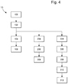
- FIG. 4 is a block diagram showing steps of a method according to the invention.
- FIG. 1 illustrates a communication system 1 , where the teachings of the present invention can be implemented.
- a mechanical wristwatch 3 that comprises no battery or any other electrical energy source.
- a wireless communication device referred to as distant reader 5 , which in this example is a mobile phone, and more specifically a smartphone.
- the distant reader 5 may belong to a user of the wristwatch 3 .
- the wristwatch 3 is arranged to set up a wireless communication link with the distant reader 5 to transmit certain information or data to the distant reader 5 .
- the wristwatch 3 is also arranged to receive certain commands, information or data from the distant reader 5 .
- These two unidirectional communication links may be implemented by using different communication standards.
- FIG. 1 further shows a server 7 .
- the server 7 belongs to, or is managed by, a manufacturer of the wristwatch 3 .
- a bidirectional data communication link can be established between the distant reader 5 and the server 7 .
- a bidirectional communication link can also be established between the server 7 and a data processing device 9 , such as a desktop computer, a laptop computer, a smartphone, a tablet or any similar data processing device that has a flashlight and/or means to transmit infrared (IR) and/or ultraviolet (UV) radiation.
- the data processing device 9 belongs to an authorized retailer of the wristwatch manufacturer.
- Two unidirectional communication links can be established between the wristwatch 3 and the data processing unit 9 .
- these two communication links may be based on two different communication standards.
- FIG. 2 is a block diagram illustrating components of the wristwatch 3 , which are useful for understanding the teachings of the present invention.
- the wristwatch comprises an energy harvesting unit 13 configured to collect or derive energy from one or more external energy sources.
- energy can be harvested from any or a combination of the following energy sources: solar radiation, other electromagnetic radiation in the wavelengths visible to the human eye, infrared radiation, ultraviolet radiation, thermal radiation and movements of the wristwatch.
- the energy unit 13 may comprise a photovoltaic cell.
- the energy harvesting unit 13 may comprise a thermoelectric generator (TEG), also called Seebeck generator, which is a device arranged to convert heat flux (temperature differences) into electrical energy through the Seebeck effect.
- TOG thermoelectric generator
- the energy harvested by the energy harvesting unit 13 can be stored in an energy storage unit 15 of the wristwatch 3 , which may be for instance a supercapacitor or a solid-state battery having both solid electrodes and solid electrolytes.
- the energy harvesting operation may be used to track an activity of the user of the wristwatch 3 .
- the energy harvesting is based on the movement of the wristwatch 3 , this gives an indication on the physical activity of the user. This also gives an indication on when and how long the wristwatch is worn.
- the energy harvesting is based on solar energy, this gives an indication on the light exposure of the wristwatch.
- the energy harvesting is based on heat flux or temperature differences, then it can be determined when the wristwatch 3 was worn by the user.
- an analysis report on an activity of the owner of the wristwatch may be computed.
- the external energy is at least in part kinetic energy resulting from movements of the wristwatch, and the report analyses at least an activity level of the wristwatch wearer during the predefined period of time.
- the external energy is at least in part solar energy resulting from solar radiations in the surrounding environment of the wristwatch, and the report analyses at least lightening levels of the wristwatch during the predefined period of time.
- the external energy is at least in part thermal energy resulting from temperature differences between the wristwatch, the wrist of the wristwatch wearer and the surrounding environment of the wristwatch, and the report analyses at least when and for long the wristwatch has been worn during the predefined period of time.
- the wristwatch 3 further comprises a wireless data transmission unit 21 , which may be a radio-frequency (RF) transmission unit operating for instance according to the Bluetooth wireless technology standard.
- RF is understood to cover any of the electromagnetic wave frequencies that lie in the range extending from around 3 kHz to 300 GHz.
- the transmission unit 21 is arranged to transmit only, i.e. it is not arranged to receive any signals in the RF band.
- a data reception path is implemented using an optical link, as explained below.
- the energy required for operating the transmission unit 21 is obtained from the energy collected by the energy harvesting unit 13 and stored in the energy storage unit 15 .
- the wristwatch 3 further comprises a receiving unit 23 for detecting and receiving an electromagnetic radiation beam.
- This electromagnetic radiation beam may be in the visible light spectrum (wavelength in the range of 400 nm to 700 nm), in the infrared spectrum (in the range of 700 nm to 1000000 nm), or in the ultraviolet spectrum (in the range of 10 nm to 400 nm).
- the word “light” is used in its broad sense and is understood to cover the whole above mentioned electromagnetic radiation spectrum.
- the wristwatch 3 also comprises an optical demodulator 17 for demodulating modulated electromagnetic radiation beams received by the receiving unit 23 , so as to retrieve a message embedded in said beam.
- a security management unit 19 of the wristwatch 3 closely cooperates with the optical demodulator 17 .
- the purpose of the security management unit 19 is to manage external access to the wristwatch and to its data. For instance, this unit determines whether or not the received message is correct and genuine.
- the security management unit 19 may also be used to select data, based on the demodulated message, to be transmitted to an external device (the data processing unit 9 or the distant reader 5 , for instance).
- the receiving unit is able to receive both optical and radio frequency waves.
- the RF receiver may be used to configure the wristwatch, in particular to define transmission intervals or transmission times.
- FIG. 3 is a circuit diagram illustrating an example implementation of such an optical-RF receiving unit 23 , which can be divided into two portions, namely an RF circuit portion 31 and an optical circuit portion 32 .
- the RF circuit portion 31 comprises an RF input-output node 33 , which is connected to a power amplifier 35 and to a low noise amplifier 37 , which in turn is connected to a mixer 39 .
- the power amplifier 35 and the low noise amplifier 37 are connected in parallel.
- the mixer 39 is also connected to the power amplifier 35 and to a delta-sigma modulator & synthesizer 41 , which in turn is connected to the demodulator 17 .
- the RF circuit portion 31 further comprises a bandpass filter 45 connected in series with a set of amplifiers 47 , which is connected to the demodulator 17 . It is to be noted that the demodulator 17 is in this example also connected to the microcontroller unit 25 .
- the optical circuit portion 32 comprises an optical input node 49 connected to an optical amplifier 51 , which in turn is connected to a multiplexer 53 with two input lines, i.e. one from the mixer 39 and the other from the optical amplifier 51 .
- the multiplexer 53 is arranged to select one of the input signals and forwards the selected input into a single output line leading to the bandpass filter 45 . In this manner, the multiplexer 53 operates as a switch. It is thus possible to use the intermediate frequency portion of the RF circuit (i.e. the RF circuit portion 31 ) and inject the optical signal into it by using the multiplexer 53 . This ensures that it is possible to use the high sensitivity of the demodulator 17 for the optical signal.
- the proposed circuit implementation makes it possible to share the receiving channels, and the chipset surface size can be reduced. It is also possible to reuse the functions of the discrete Fourier transform (DFT) at low power, which are already present in the chipset, and which allow separating up to 255 different bins.
- DFT discrete Fourier transform
- the wristwatch 3 comprises a microcontroller 25 for managing the overall operation and controlling the other components of the wristwatch.
- the wristwatch 3 has three distinct operational modes.
- a first mode referred to as a normal mode
- energy is harvested by the energy harvesting unit 13 (step 100 ) and stored in the energy storage unit 15 (step 102 ).
- an analysis report on an activity of the owner of the wristwatch 3 is generated (step 104 ), based at least on the times and durations of availability of the external energy.
- the analysis report is transmitted to the distant reader 5 by using the transmission unit 21 (step 106 ).
- the transmission is carried out by using the Bluetooth wireless technology standard.
- the user of the wristwatch 3 may configure the wristwatch 3 to define a transmission schedule. It is possible to define the data transmissions to take place at (a) given time instant(s) each day or on given dates only, i.e. the transmissions take place at regular time intervals. Alternatively, instead of defining transmission times, a time interval between consecutive data transmissions may be defined. Furthermore, it is also possible to configure the wristwatch 3 to initiate a data transmission as soon as sufficient energy has been collected.
- the wristwatch 3 detects, via the receiving unit 23 , an electromagnetic radiation beam (step 304 ). Then, the wristwatch retrieves a diagnosis request embedded in said beam (step 306 ). The diagnosis request is addressed or dedicated to the wristwatch 3 . The request advantageously identifies the entity sending the request. The wristwatch 3 may then use a challenge-response authentication protocol to authenticate the entity who issued the request (step 308 ). For this purpose, a challenge code issued by the wristwatch 3 may be used. However, the challenge code may initially be issued by the manufacturer of the wristwatch 3 and provided to the wristwatch 3 by the manufacturer. Thus, the manufacturer may administer the challenge-response authentication process.
- the wristwatch 3 may thus send the received challenge code to the data processing device 9 , which may need to authenticate itself with the server 7 of the manufacturer before replying to the wristwatch 3 .
- the received request may comprise information that allows the wristwatch 3 to contact the data processing device 9 or any other device indicated in the modulated request.
- the wristwatch 3 detects an alarm (step 204 ).
- This alarm refers to a malfunction of an element or a function of the wristwatch 3 .
- the detected malfunction may relate to a sealing problem or a timekeeping problem or to any other detectable problem.
- the wristwatch 3 If an alarm has been detected, and assuming enough energy has been collected, then the wristwatch 3 generates an alarm message representative of the detected malfunction (step 206 ). Then, when or after the harvested energy quantity reaches the threshold, the transmission unit 21 sends the alarm message to the data processing device 9 (step 208 ).
- the user of the data processing device 9 may then review the alarm message on the screen of the device and optionally forward the alarm message to the server 7 of the manufacturer. The manufacturer may then take appropriate actions to solve the problem.
Landscapes
- Physics & Mathematics (AREA)
- General Physics & Mathematics (AREA)
- Engineering & Computer Science (AREA)
- Computer Networks & Wireless Communication (AREA)
- Life Sciences & Earth Sciences (AREA)
- Sustainable Development (AREA)
- Power Engineering (AREA)
- Electric Clocks (AREA)
- Electromechanical Clocks (AREA)
- Management, Administration, Business Operations System, And Electronic Commerce (AREA)
Abstract
Description
Claims (10)
Applications Claiming Priority (3)
| Application Number | Priority Date | Filing Date | Title |
|---|---|---|---|
| EP18178507.2A EP3584646A1 (en) | 2018-06-19 | 2018-06-19 | Method for providing information about a mechanical wristwatch |
| EP18178507.2 | 2018-06-19 | ||
| EP18178507 | 2018-06-19 |
Publications (2)
| Publication Number | Publication Date |
|---|---|
| US20190387288A1 US20190387288A1 (en) | 2019-12-19 |
| US10827237B2 true US10827237B2 (en) | 2020-11-03 |
Family
ID=62712863
Family Applications (1)
| Application Number | Title | Priority Date | Filing Date |
|---|---|---|---|
| US16/397,254 Active US10827237B2 (en) | 2018-06-19 | 2019-04-29 | Method for providing information about a mechanical wristwatch |
Country Status (4)
| Country | Link |
|---|---|
| US (1) | US10827237B2 (en) |
| EP (1) | EP3584646A1 (en) |
| JP (1) | JP6872580B2 (en) |
| CN (1) | CN110618600B (en) |
Families Citing this family (2)
| Publication number | Priority date | Publication date | Assignee | Title |
|---|---|---|---|---|
| JP7559538B2 (en) * | 2020-12-22 | 2024-10-02 | セイコーエプソン株式会社 | Electronic clock |
| JP7559539B2 (en) * | 2020-12-22 | 2024-10-02 | セイコーエプソン株式会社 | Electronic clock |
Citations (8)
| Publication number | Priority date | Publication date | Assignee | Title |
|---|---|---|---|---|
| JP2006055189A (en) | 2004-08-17 | 2006-03-02 | Citizen Watch Co Ltd | Activity grasping system |
| US20150128733A1 (en) * | 2013-11-12 | 2015-05-14 | Qualcomm Incorporated | Methods, devices and systems for self charging sensors |
| US20160164746A1 (en) | 2014-12-05 | 2016-06-09 | Accenture Global Services Limited | Network component placement architecture |
| US20160291550A1 (en) * | 2015-03-31 | 2016-10-06 | Superior Communications, Inc. | Watch strap battery |
| WO2016181605A1 (en) | 2015-05-12 | 2016-11-17 | ソニー株式会社 | Management device, individual entity management system, and individual entity search system |
| US20170185048A1 (en) | 2015-12-29 | 2017-06-29 | Michael M. Yuen | Smartwatch assemblies having analog dials with specific functionalities |
| WO2017130912A1 (en) | 2016-01-29 | 2017-08-03 | セイコーエプソン株式会社 | Wearable device, device to be controlled, short-distance wireless communication network, communication system, control system, and remote control method |
| JP2017138864A (en) | 2016-02-05 | 2017-08-10 | 三菱電機株式会社 | Communication apparatus and emergency signal transmission system |
Family Cites Families (17)
| Publication number | Priority date | Publication date | Assignee | Title |
|---|---|---|---|---|
| CH679356B5 (en) * | 1990-06-07 | 1992-08-14 | Ebauchesfabrik Eta Ag | |
| JP3743819B2 (en) * | 1999-04-09 | 2006-02-08 | カシオ計算機株式会社 | Electronic device with clock function, time information correction method |
| CN1354402A (en) * | 2001-11-30 | 2002-06-19 | 精中(珠海)表业有限公司 | Clock system |
| CN2670981Y (en) * | 2003-12-01 | 2005-01-12 | 李志富 | Clock with mottoes |
| CN201160530Y (en) * | 2007-12-06 | 2008-12-10 | 李康颖 | Intelligent shoes for testing amount of exercise |
| EP2635938B1 (en) * | 2010-11-01 | 2022-09-07 | NIKE Innovate C.V. | Wearable device assembly having athletic functionality |
| CN202189239U (en) * | 2011-07-30 | 2012-04-11 | 常州蓝城信息科技有限公司 | Health watch |
| EP2775916A4 (en) * | 2011-11-08 | 2015-07-08 | J & M Shuler Inc | Method and system for providing versatile nirs sensors |
| CN103885323A (en) * | 2012-12-20 | 2014-06-25 | 陈友铖 | Solar-powered outdoor clock |
| JP6209840B2 (en) * | 2013-03-27 | 2017-10-11 | セイコーエプソン株式会社 | Quantum interference devices, atomic oscillators, electronic equipment, and moving objects |
| EP3074838A4 (en) * | 2013-11-29 | 2017-08-02 | Motiv Inc. | Wearable computing device |
| CN103699000A (en) * | 2013-12-11 | 2014-04-02 | 中山市永衡日用制品有限公司 | Smart watch with vibration power supply |
| CN105686254A (en) * | 2014-11-27 | 2016-06-22 | 西安丁子电子信息科技有限公司 | Smart band with temperature difference charging function |
| JP6712878B2 (en) * | 2016-03-10 | 2020-06-24 | 旭化成エレクトロニクス株式会社 | Measuring system and biological information measuring method |
| EP3333649B1 (en) * | 2016-12-09 | 2025-07-30 | The Swatch Group Research and Development Ltd | Method for determining parameters for adjusting the operation of a mechanical watch |
| CN206472955U (en) * | 2016-12-27 | 2017-09-08 | 孔心悦 | A kind of multifunctional movement bracelet with charger baby |
| CN206848707U (en) * | 2017-06-30 | 2018-01-05 | 云南电网有限责任公司文山供电局 | A kind of device for judging current conversion station master clock failure |
-
2018
- 2018-06-19 EP EP18178507.2A patent/EP3584646A1/en active Pending
-
2019
- 2019-04-29 US US16/397,254 patent/US10827237B2/en active Active
- 2019-05-27 JP JP2019098370A patent/JP6872580B2/en active Active
- 2019-06-11 CN CN201910499319.6A patent/CN110618600B/en active Active
Patent Citations (9)
| Publication number | Priority date | Publication date | Assignee | Title |
|---|---|---|---|---|
| JP2006055189A (en) | 2004-08-17 | 2006-03-02 | Citizen Watch Co Ltd | Activity grasping system |
| US20150128733A1 (en) * | 2013-11-12 | 2015-05-14 | Qualcomm Incorporated | Methods, devices and systems for self charging sensors |
| US20160164746A1 (en) | 2014-12-05 | 2016-06-09 | Accenture Global Services Limited | Network component placement architecture |
| US20160291550A1 (en) * | 2015-03-31 | 2016-10-06 | Superior Communications, Inc. | Watch strap battery |
| WO2016181605A1 (en) | 2015-05-12 | 2016-11-17 | ソニー株式会社 | Management device, individual entity management system, and individual entity search system |
| US20170185048A1 (en) | 2015-12-29 | 2017-06-29 | Michael M. Yuen | Smartwatch assemblies having analog dials with specific functionalities |
| US20180101140A1 (en) | 2015-12-29 | 2018-04-12 | Michael M. Yuen | Smartwatch assemblies having analog dials with specific functionalities |
| WO2017130912A1 (en) | 2016-01-29 | 2017-08-03 | セイコーエプソン株式会社 | Wearable device, device to be controlled, short-distance wireless communication network, communication system, control system, and remote control method |
| JP2017138864A (en) | 2016-02-05 | 2017-08-10 | 三菱電機株式会社 | Communication apparatus and emergency signal transmission system |
Non-Patent Citations (2)
| Title |
|---|
| European Search Report dated Dec. 11, 2018 in European Application 18178507.2 filed on Jun. 19, 2018. |
| Japanese Office Action dated Jul. 7, 2020, issued in Japanese Patent Application No. 2019-098370 (with English translation). |
Also Published As
| Publication number | Publication date |
|---|---|
| US20190387288A1 (en) | 2019-12-19 |
| JP2019219386A (en) | 2019-12-26 |
| CN110618600A (en) | 2019-12-27 |
| JP6872580B2 (en) | 2021-05-19 |
| CN110618600B (en) | 2021-09-03 |
| EP3584646A1 (en) | 2019-12-25 |
Similar Documents
| Publication | Publication Date | Title |
|---|---|---|
| Varshney et al. | Tunnelscatter: Low power communication for sensor tags using tunnel diodes | |
| US11824370B2 (en) | Retrodirective wireless power transfer via backscattering | |
| US11838785B2 (en) | Messaging devices and methods | |
| US20140247141A1 (en) | Monitoring device with wireless communication over non-contiguous channels | |
| JP6241613B2 (en) | Electronic device system, terminal device, electronic device system control method, and control program | |
| US10827237B2 (en) | Method for providing information about a mechanical wristwatch | |
| US20250247779A1 (en) | Communication method and device | |
| Torrisi et al. | Zero power energy-aware communication for transiently-powered sensing systems | |
| US11374676B2 (en) | Optical device and hub node for an optical network | |
| US20250089108A1 (en) | Communication method, and devices | |
| HK40018363A (en) | Method for providing information about a mechanical wristwatch | |
| HK40018363B (en) | Method for providing information about a mechanical wristwatch | |
| Gong et al. | Practical Backscatter Communication for the Internet of Things | |
| EP3921999B1 (en) | Low consumption hub and detector configured to communicate with this hub | |
| US20240223270A1 (en) | Satellite backscatter communication | |
| JPH05292577A (en) | Wireless communication system | |
| CN112218248A (en) | Method and system for collecting user activity information | |
| US20250386192A1 (en) | Communication method and apparatus, and communication device | |
| EP4207849A1 (en) | Electronic identification device and scanning device for scanning the electronic identification device | |
| WO2025035428A1 (en) | Data transmission method, first device, and second device | |
| WO2025152026A1 (en) | Positioning method, terminal device, trigger device, and network device | |
| WO2024148511A1 (en) | Wireless communication method and device | |
| CN117949983A (en) | Satellite navigation message updating method, device, receiver and storage medium |
Legal Events
| Date | Code | Title | Description |
|---|---|---|---|
| AS | Assignment |
Owner name: THE SWATCH GROUP RESEARCH AND DEVELOPMENT LTD, SWI Free format text: ASSIGNMENT OF ASSIGNORS INTEREST;ASSIGNORS:SCORDILIS, THIERRY;CASAGRANDE, ARNAUD;DE ROSA, LUCA;AND OTHERS;REEL/FRAME:049021/0243 Effective date: 20190423 Owner name: THE SWATCH GROUP RESEARCH AND DEVELOPMENT LTD, SWITZERLAND Free format text: ASSIGNMENT OF ASSIGNORS INTEREST;ASSIGNORS:SCORDILIS, THIERRY;CASAGRANDE, ARNAUD;DE ROSA, LUCA;AND OTHERS;REEL/FRAME:049021/0243 Effective date: 20190423 |
|
| FEPP | Fee payment procedure |
Free format text: ENTITY STATUS SET TO UNDISCOUNTED (ORIGINAL EVENT CODE: BIG.); ENTITY STATUS OF PATENT OWNER: LARGE ENTITY |
|
| STPP | Information on status: patent application and granting procedure in general |
Free format text: NON FINAL ACTION MAILED |
|
| STPP | Information on status: patent application and granting procedure in general |
Free format text: RESPONSE TO NON-FINAL OFFICE ACTION ENTERED AND FORWARDED TO EXAMINER |
|
| STPP | Information on status: patent application and granting procedure in general |
Free format text: NOTICE OF ALLOWANCE MAILED -- APPLICATION RECEIVED IN OFFICE OF PUBLICATIONS |
|
| STPP | Information on status: patent application and granting procedure in general |
Free format text: PUBLICATIONS -- ISSUE FEE PAYMENT VERIFIED |
|
| STCF | Information on status: patent grant |
Free format text: PATENTED CASE |
|
| STPP | Information on status: patent application and granting procedure in general |
Free format text: PUBLICATIONS -- ISSUE FEE PAYMENT VERIFIED |
|
| STCF | Information on status: patent grant |
Free format text: PATENTED CASE |
|
| MAFP | Maintenance fee payment |
Free format text: PAYMENT OF MAINTENANCE FEE, 4TH YEAR, LARGE ENTITY (ORIGINAL EVENT CODE: M1551); ENTITY STATUS OF PATENT OWNER: LARGE ENTITY Year of fee payment: 4 |