US10823401B2 - Burner system including a non-planar perforated flame holder - Google Patents
Burner system including a non-planar perforated flame holder Download PDFInfo
- Publication number
- US10823401B2 US10823401B2 US16/137,339 US201816137339A US10823401B2 US 10823401 B2 US10823401 B2 US 10823401B2 US 201816137339 A US201816137339 A US 201816137339A US 10823401 B2 US10823401 B2 US 10823401B2
- Authority
- US
- United States
- Prior art keywords
- flame holder
- perforated flame
- planar
- fuel
- perforations
- Prior art date
- Legal status (The legal status is an assumption and is not a legal conclusion. Google has not performed a legal analysis and makes no representation as to the accuracy of the status listed.)
- Active, expires
Links
Images


Classifications
-
- F—MECHANICAL ENGINEERING; LIGHTING; HEATING; WEAPONS; BLASTING
- F23—COMBUSTION APPARATUS; COMBUSTION PROCESSES
- F23D—BURNERS
- F23D14/00—Burners for combustion of a gas, e.g. of a gas stored under pressure as a liquid
- F23D14/12—Radiant burners
- F23D14/14—Radiant burners using screens or perforated plates
- F23D14/145—Radiant burners using screens or perforated plates combustion being stabilised at a screen or a perforated plate
-
- F—MECHANICAL ENGINEERING; LIGHTING; HEATING; WEAPONS; BLASTING
- F23—COMBUSTION APPARATUS; COMBUSTION PROCESSES
- F23D—BURNERS
- F23D2203/00—Gaseous fuel burners
- F23D2203/10—Flame diffusing means
- F23D2203/101—Flame diffusing means characterised by surface shape
- F23D2203/1017—Flame diffusing means characterised by surface shape curved
-
- F—MECHANICAL ENGINEERING; LIGHTING; HEATING; WEAPONS; BLASTING
- F23—COMBUSTION APPARATUS; COMBUSTION PROCESSES
- F23D—BURNERS
- F23D2203/00—Gaseous fuel burners
- F23D2203/10—Flame diffusing means
- F23D2203/102—Flame diffusing means using perforated plates
-
- F—MECHANICAL ENGINEERING; LIGHTING; HEATING; WEAPONS; BLASTING
- F23—COMBUSTION APPARATUS; COMBUSTION PROCESSES
- F23D—BURNERS
- F23D2203/00—Gaseous fuel burners
- F23D2203/10—Flame diffusing means
- F23D2203/104—Grids, e.g. honeycomb grids
-
- F—MECHANICAL ENGINEERING; LIGHTING; HEATING; WEAPONS; BLASTING
- F23—COMBUSTION APPARATUS; COMBUSTION PROCESSES
- F23D—BURNERS
- F23D2212/00—Burner material specifications
- F23D2212/10—Burner material specifications ceramic
- F23D2212/103—Fibres
Definitions
- PCT/US2014/016628 entitled “PERFORATED FLAME HOLDER AND BURNER INCLUDING A PERFORATED FLAME HOLDER,” filed Feb. 14, 2014, now expired.
- International Patent Application No. PCT/US2014/016628 claims priority benefit of U.S. Provisional Patent Application No. 61/765,022, entitled “PERFORATED FLAME HOLDER AND BURNER INCLUDING A PERFORATED FLAME HOLDER,” filed Feb. 14, 2013.
- U.S. patent application Ser. No. 15/236,862 is also a Continuation-in-Part of co-pending U.S. patent application Ser. No. 15/215,401, entitled “LOW NO X FIRE TUBE BOILER,” filed Jul. 20, 2016.
- a non-planar perforated flame holder includes an input face configured to receive a fuel-air mixture.
- the non-planar perforated flame holder includes an output face configured to emit products of a combustion reaction of the fuel-air mixture.
- the non-planar perforated flame holder includes a non-planar flame holder body having a plurality of perforations extending from the input face to the output face and collectively configured to promote the combustion reaction of the fuel-air mixture within the perforations.
- a combustion system includes a fuel nozzle configured to emit a fuel stream.
- the combustion system includes a non-planar perforated flame holder positioned downstream from the fuel nozzle to receive a fuel-air mixture.
- the fuel-air mixture can be an air-entrained mixture of the fuel stream.
- the non-planar perforated flame holder includes an input face configured to receive the fuel-air mixture.
- the non-planar perforated flame holder includes an output face configured to emit products of a combustion reaction of the fuel-air mixture.
- the non-planar perforated flame holder includes a non-planar flame holder body having a plurality of perforations extending from the input face to the output face and collectively configured to promote the combustion reaction of the fuel-air mixture within the perforations.
- a method of operating a combustion system includes outputting fuel from a nozzle to generate a fuel-air mixture.
- the method includes receiving the fuel-air mixture with a non-planar perforated flame holder.
- the non-planar perforated flame holder includes a plurality of perforations that extend from an input face to an output face of the non-planar perforated flame holder.
- the method includes sustaining a combustion reaction of the fuel-air mixture substantially within the plurality of perforations.
- FIG. 1 is a side sectional view of a perforated flame holder that includes one or more non-planar faces, according to one embodiment.
- FIG. 2 is a simplified perspective view of a burner system including a perforated flame holder, according to an embodiment.
- FIG. 3 is a side sectional diagram of a portion of the perforated flame holder of FIGS. 1 and 2 , according to an embodiment.
- FIG. 4 is a flow chart showing a method for operating a burner system including the perforated flame holder of FIGS. 1, 2 and 3 , according to an embodiment.
- FIG. 5 is a simplified perspective view of a combustion system including a non-planar perforated flame holder, according to an embodiment.
- FIG. 6 is a simplified perspective view of a combustion system including a non-planar perforated flame holder, according to an embodiment.
- FIG. 7A is a simplified perspective view of a non-planar perforated flame holder, according to an embodiment.
- FIG. 7B is a simplified side sectional view of the non-planar perforated flame holder of FIG. 7A , according to an embodiment.
- FIG. 7C is a simplified plan view of an alternate implementation of the non-planar perforated flame holder of FIG. 7A , according to an embodiment.
- FIG. 8 is a simplified side sectional view of a non-planar perforated flame holder, according to an embodiment.
- FIG. 9 is a simplified side sectional view of a non-planar perforated flame holder, according to an embodiment.
- FIG. 10 is a flow diagram of a method of operating a combustion system, according to an embodiment.
- a non-planar perforated flame holder can equalize fuel-air mixture flow rates across the input face of the perforated flame holder.
- fuel and oxidant flow are characterized by a series of vortices (e.g., as a Von Karman vortex street). Accordingly, an instantaneous maximum flow velocity of a fuel-air mixture is unpredictable with respect to where it occurs, relative to an axis of a fuel nozzle.
- instantaneous flow rate may have the highest probability of being maximum along the nozzle axis (depending on nozzle geometry) at any instant in time, and the probability of encountering the maximum instantaneous flow rate declines off-axis.
- fuel and oxidant mixture velocity may be highest along a fuel stream axis. Accordingly, fuel flow rate may be generally equalized by placing a central portion of a perforated flame holder farther away from a fuel nozzle and a peripheral portion of the perforated flame holder closer to the fuel nozzle.
- a non-planar perforated flame holder can provide superior mechanical robustness compared to a planar perforated flame holder.
- a planar perforated flame holder can place its input face under a concentrated tensile load to maintain beam strength of the flame holder structure.
- tensile load on a ceramic, cementatious, or refractory fiber perforated flame holder can limit mechanical reliability due to tensile failure.
- inclusion of metal alloy structures to support tensile loads can be undesirable due to temperature, cost, radiation pattern blockage, and/or other concerns.
- forming a perforated flame holder in an arch can provide reduced tensile loading and increase mechanical robustness.
- forming the perforated flame holder in the shape of a catenary arch can substantially eliminate tensile loading on the perforated flame holder.
- forming all or a portion of the non-planar perforated flame holder in a downward sag can spread out tensile loading across the section of a perforated flame holder and reduce tensile load concentration.
- a catenary suspension can equalize tensile loading across the section.
- a non-planar perforated flame holder can provide a selected thermal radiation pattern from the open faces of the perforated flame holder.
- the inventors have noted that most thermal radiation is often emitted from perforation walls near the input face and output face of the perforated flame holder.
- the radiating surface view factor can be increased in a selected direction and decreased in another selected direction. This can be used, for example, to maintain radiative heating of one portion of a perforated flame holder from another portion of the perforated flame holder.
- view factor selection can be used to minimize or maximize thermal radiation onto heat transfer surfaces, support structures, fuel and oxidant sources, etc. within a furnace.
- FIG. 1 is a side sectional view of a perforated flame holder 101 that includes one or more non-planar faces to generally equalize fuel flow rate, provide mechanical robustness, and define thermal radiation patterns, according to one embodiment.
- the perforated flame holder 101 may be non-planar shaped.
- the perforated flame holder 101 includes an input face 104 and an output face 106 .
- the input face 104 is disposed towards the direction of a source of a fuel-air mixture, and is configured to receive the fuel-air mixture from the source.
- the output face 106 is disposed away from the source of the fuel-air mixture, and is configured to emit combustion products.
- the perforated flame holder 101 also includes a non-planar perforated flame holder body 108 and a plurality of perforations 110 that extend through the flame holder body 108 from the input face 104 to the output face 106 .
- An example of a combustion product generated by the perforated flame holder 101 in response to receipt of the fuel-air mixture, is a stable primary flame 112 .
- FIG. 2 is a simplified diagram of a burner system 200 including a perforated flame holder 102 configured to hold a combustion reaction, according to an embodiment.
- a perforated flame holder 102 configured to hold a combustion reaction
- the terms perforated flame holder, perforated reaction holder, porous flame holder, porous reaction holder, duplex, and duplex tile shall be considered synonymous unless further definition is provided.
- perforated flame holders 102 described herein can support very clean combustion. Specifically, in experimental use of systems 200 ranging from pilot scale to full scale, output of oxides of nitrogen (NOx) was measured to range from low single digit parts per million (ppm) down to undetectable (less than 1 ppm) concentration of NOx at the stack. These remarkable results were measured at 3% (dry) oxygen (O 2 ) concentration with undetectable carbon monoxide (CO) at stack temperatures typical of industrial furnace applications (1400-1600° F.).
- NOx oxides of nitrogen
- the burner system 200 includes a fuel and oxidant source 202 disposed to output fuel and oxidant into a combustion volume 204 to form a fuel and oxidant mixture 206 .
- fuel and oxidant mixture and fuel stream may be used interchangeably and considered synonymous depending on the context, unless further definition is provided.
- combustion volume, combustion chamber, furnace volume, and the like shall be considered synonymous unless further definition is provided.
- the perforated flame holder 102 is disposed in the combustion volume 204 and positioned to receive the fuel and oxidant mixture 206 .
- FIG. 3 is a side sectional diagram 300 of a portion of the perforated flame holder 102 of FIGS. 1 and 2 , according to an embodiment.
- the perforated flame holder 102 includes a perforated flame holder body 208 defining a plurality of perforations 210 aligned to receive the fuel and oxidant mixture 206 from the fuel and oxidant source 202 .
- the terms perforation, pore, aperture, elongated aperture, and the like, in the context of the perforated flame holder 102 shall be considered synonymous unless further definition is provided.
- the perforations 210 are configured to collectively hold a combustion reaction 302 supported by the fuel and oxidant mixture 206 .
- the fuel can include hydrogen, a hydrocarbon gas, a vaporized hydrocarbon liquid, an atomized hydrocarbon liquid, or a powdered or pulverized solid.
- the fuel can be a single species or can include a mixture of gas(es), vapor(s), atomized liquid(s), and/or pulverized solid(s).
- the fuel in a process heater application the fuel can include fuel gas or byproducts from the process that include carbon monoxide (CO), hydrogen (H 2 ), and methane (CH 4 ).
- the fuel can include natural gas (mostly CH 4 ) or propane (C 3 H 8 ).
- the fuel can include #2 fuel oil or #6 fuel oil. Dual fuel applications and flexible fuel applications are similarly contemplated by the inventors.
- the oxidant can include oxygen carried by air, flue gas, and/or can include another oxidant, either pure or carried by a carrier gas.
- the terms oxidant and oxidizer shall be considered synonymous herein.
- the perforated flame holder body 208 can be bounded by an input face 212 disposed to receive the fuel and oxidant mixture 206 , an output face 214 facing away from the fuel and oxidant source 202 , and a peripheral surface 216 defining a lateral extent of the perforated flame holder 102 .
- the plurality of perforations 210 which are defined by the perforated flame holder body 208 extend from the input face 212 to the output face 214 .
- the plurality of perforations 210 can receive the fuel and oxidant mixture 206 at the input face 212 .
- the fuel and oxidant mixture 206 can then combust in or near the plurality of perforations 210 and combustion products can exit the plurality of perforations 210 at or near the output face 214 .
- the perforated flame holder 102 is configured to hold a majority of the combustion reaction 302 within the perforations 210 .
- more than half the molecules of fuel output into the combustion volume 204 by the fuel and oxidant source 202 may be converted to combustion products between the input face 212 and the output face 214 of the perforated flame holder 102 .
- more than half of the heat or thermal energy output by the combustion reaction 302 may be output between the input face 212 and the output face 214 of the perforated flame holder 102 .
- the terms heat, heat energy, and thermal energy shall be considered synonymous unless further definition is provided.
- heat energy and thermal energy refer generally to the released chemical energy initially held by reactants during the combustion reaction 302 .
- heat, heat energy and thermal energy correspond to a detectable temperature rise undergone by real bodies characterized by heat capacities.
- the perforations 210 can be configured to collectively hold at least 80% of the combustion reaction 302 between the input face 212 and the output face 214 of the perforated flame holder 102 .
- the inventors produced a combustion reaction 302 that was apparently wholly contained in the perforations 210 between the input face 212 and the output face 214 of the perforated flame holder 102 .
- the perforated flame holder 102 can support combustion between the input face 212 and output face 214 when combustion is “time-averaged.” For example, during transients, such as before the perforated flame holder 102 is fully heated, or if too high a (cooling) load is placed on the system, the combustion may travel somewhat downstream from the output face 214 of the perforated flame holder 102 . Alternatively, if the cooling load is relatively low and/or the furnace temperature reaches a high level, the combustion may travel somewhat upstream of the input face 212 of the perforated flame holder 102 .
- Such transient huffing or flashback is generally short in duration such that, on a time-averaged basis, a majority of combustion occurs within the perforations 210 of the perforated flame holder 102 , between the input face 212 and the output face 214 .
- the inventors have noted apparent combustion occurring downstream from the output face 214 of the perforated flame holder 102 , but still a majority of combustion occurred within the perforated flame holder 102 as evidenced by continued visible glow from the perforated flame holder 102 that was observed.
- the perforated flame holder 102 can be configured to receive heat from the combustion reaction 302 and output a portion of the received heat as thermal radiation 304 to heat-receiving structures (e.g., furnace walls and/or radiant section working fluid tubes) in or adjacent to the combustion volume 204 .
- heat-receiving structures e.g., furnace walls and/or radiant section working fluid tubes
- terms such as radiation, thermal radiation, radiant heat, heat radiation, etc. are to be construed as being substantially synonymous, unless further definition is provided. Specifically, such terms refer to blackbody-type radiation of electromagnetic energy, primarily at infrared wavelengths, but also at visible wavelengths owing to elevated temperature of the perforated flame holder body 208 .
- the perforated flame holder 102 outputs another portion of the received heat to the fuel and oxidant mixture 206 received at the input face 212 of the perforated flame holder 102 .
- the perforated flame holder body 208 may receive heat from the combustion reaction 302 at least in heat receiving regions 306 of perforation walls 308 .
- Experimental evidence has suggested to the inventors that the position of the heat receiving regions 306 , or at least the position corresponding to a maximum rate of receipt of heat, can vary along the length of the perforation walls 308 .
- the location of maximum receipt of heat was apparently between 1 ⁇ 3 and 1 ⁇ 2 of the distance from the input face 212 to the output face 214 (i.e., somewhat nearer to the input face 212 than to the output face 214 ).
- the perforated flame holder body 208 can be characterized by a heat capacity.
- the perforated flame holder body 208 may hold thermal energy from the combustion reaction 302 in an amount corresponding to the heat capacity multiplied by temperature rise, and transfer the thermal energy from the heat receiving regions 306 to heat output regions 310 of the perforation walls 308 .
- the heat output regions 310 are nearer to the input face 212 than are the heat receiving regions 306 .
- the perforated flame holder body 208 can transfer heat from the heat receiving regions 306 to the heat output regions 310 via thermal radiation, depicted graphically as 304 .
- the perforated flame holder body 208 can transfer heat from the heat receiving regions 306 to the heat output regions 310 via heat conduction along heat conduction paths 312 .
- the inventors contemplate that multiple heat transfer mechanisms including conduction, radiation, and possibly convection may be operative in transferring heat from the heat receiving regions 306 to the heat output regions 310 .
- the perforated flame holder 102 may act as a heat source to maintain the combustion reaction 302 , even under conditions where a combustion reaction 302 would not be stable when supported from a conventional flame holder.
- the perforated flame holder 102 causes the combustion reaction 302 to begin within thermal boundary layers 314 formed adjacent to walls 308 of the perforations 210 .
- combustion is generally understood to include a large number of individual reactions, and since a large portion of combustion energy is released within the perforated flame holder 102 , it is apparent that at least a majority of the individual reactions occur within the perforated flame holder 102 .
- the flow is split into portions that respectively travel through individual perforations 210 .
- the hot perforated flame holder body 208 transfers heat to the fluid, notably within thermal boundary layers 314 that progressively thicken as more and more heat is transferred to the incoming fuel and oxidant mixture 206 .
- a combustion temperature e.g., the auto-ignition temperature of the fuel
- the reactants continue to flow while a chemical ignition delay time elapses, over which time the combustion reaction 302 occurs. Accordingly, the combustion reaction 302 is shown as occurring within the thermal boundary layers 314 .
- the thermal boundary layers 314 merge at a merger point 316 .
- the merger point 316 lies between the input face 212 and output face 214 that define the ends of the perforations 210 .
- the combustion reaction 302 outputs more heat to the perforated flame holder body 208 than it receives from the perforated flame holder body 208 .
- the heat is received at the heat receiving region 306 , is held by the perforated flame holder body 208 , and is transported to the heat output region 310 nearer to the input face 212 , where the heat is transferred into the cool reactants (and any included diluent) to bring the reactants to the ignition temperature.
- each of the perforations 210 is characterized by a length L defined as a reaction fluid propagation path length between the input face 212 and the output face 214 of the perforated flame holder 102 .
- the term reaction fluid refers to matter that travels through a perforation 210 .
- the reaction fluid includes the fuel and oxidant mixture 206 (optionally including nitrogen, flue gas, and/or other “non-reactive” species).
- the reaction fluid may include plasma associated with the combustion reaction 302 , molecules of reactants and their constituent parts, any non-reactive species, reaction intermediates (including transition states), and reaction products.
- the reaction fluid may include reaction products and byproducts, non-reactive gas, and excess oxidant.
- the plurality of perforations 210 can be each characterized by a transverse dimension D between opposing perforation walls 308 .
- the inventors have found that stable combustion can be maintained in the perforated flame holder 102 if the length L of each perforation 210 is at least four times the transverse dimension D of the perforation. In other embodiments, the length L can be greater than six times the transverse dimension D. For example, experiments have been run where L is at least eight, at least twelve, at least sixteen, and at least twenty-four times the transverse dimension D.
- the length L is sufficiently long for thermal boundary layers 314 to form adjacent to the perforation walls 308 in a reaction fluid flowing through the perforations 210 to converge at merger points 316 within the perforations 210 between the input face 212 and the output face 214 of the perforated flame holder 102 .
- L/D ratios between 12 and 48 to work well (i.e., produce low NOx, produce low CO, and maintain stable combustion).
- the perforated flame holder body 208 can be configured to convey heat between adjacent perforations 210 .
- the heat conveyed between adjacent perforations 210 can be selected to cause heat output from the combustion reaction portion 302 in a first perforation 210 to supply heat to stabilize a combustion reaction portion 302 in an adjacent perforation 210 .
- the fuel and oxidant source 202 can further include a fuel nozzle 218 , configured to output fuel, and an oxidant source 220 configured to output a fluid including the oxidant.
- the fuel nozzle 218 can be configured to output pure fuel.
- the oxidant source 220 can be configured to output combustion air carrying oxygen, and optionally, flue gas.
- the perforated flame holder 102 can be held by a perforated flame holder support structure 222 configured to hold the perforated flame holder 102 at a dilution distance D D away from the fuel nozzle 218 .
- the fuel nozzle 218 can be configured to emit a fuel jet selected to entrain the oxidant to form the fuel and oxidant mixture 206 as the fuel jet and oxidant travel along a path to the perforated flame holder 102 through the dilution distance D D between the fuel nozzle 218 and the perforated flame holder 102 .
- the oxidant or combustion air source can be configured to entrain the fuel and the fuel and oxidant travel through the dilution distance D D .
- a flue gas recirculation path 224 can be provided.
- the fuel nozzle 218 can be configured to emit a fuel jet selected to entrain the oxidant and to entrain flue gas as the fuel jet travels through the dilution distance D D between the fuel nozzle 218 and the input face 212 of the perforated flame holder 102 .
- the fuel nozzle 218 can be configured to emit the fuel through one or more fuel orifices 226 having an inside diameter dimension that is referred to as “nozzle diameter.”
- the perforated flame holder support structure 222 can support the perforated flame holder 102 to receive the fuel and oxidant mixture 206 at the distance D D away from the fuel nozzle 218 greater than 20 times the nozzle diameter.
- the perforated flame holder 102 is disposed to receive the fuel and oxidant mixture 206 at the distance D D away from the fuel nozzle 218 between 100 times and 1100 times the nozzle diameter.
- the perforated flame holder support structure 222 is configured to hold the perforated flame holder 102 at a distance about 200 times or more of the nozzle diameter away from the fuel nozzle 218 .
- the fuel and oxidant mixture 206 travels about 200 times the nozzle diameter or more, the mixture is sufficiently homogenized to cause the combustion reaction 302 to produce minimal NOx.
- the fuel and oxidant source 202 can alternatively include a premix fuel and oxidant source, according to an embodiment.
- a premix fuel and oxidant source can include a premix chamber (not shown), a fuel nozzle configured to output fuel into the premix chamber, and an oxidant (e.g., combustion air) channel configured to output the oxidant into the premix chamber.
- a flame arrestor can be disposed between the premix fuel and oxidant source and the perforated flame holder 102 and be configured to prevent flame flashback into the premix fuel and oxidant source.
- the oxidant source 220 can include a blower configured to force the oxidant through the fuel and oxidant source 202 .
- the support structure 222 can be configured to support the perforated flame holder 102 from a floor or wall (not shown) of the combustion volume 204 , for example. In another embodiment, the support structure 222 supports the perforated flame holder 102 from the fuel and oxidant source 202 . Alternatively, the support structure 222 can suspend the perforated flame holder 102 from an overhead structure (such as a flue, in the case of an up-fired system). The support structure 222 can support the perforated flame holder 102 in various orientations and directions.
- the perforated flame holder 102 can include a single perforated flame holder body 208 .
- the perforated flame holder 102 can include a plurality of adjacent perforated flame holder sections that collectively provide a tiled perforated flame holder 102 .
- the perforated flame holder support structure 222 can be configured to support the plurality of perforated flame holder sections.
- the perforated flame holder support structure 222 can include a metal superalloy, a cementatious, and/or ceramic refractory material.
- the plurality of adjacent perforated flame holder sections can be joined with a fiber reinforced refractory cement.
- the perforated flame holder 102 can have a width dimension W between opposite sides of the peripheral surface 216 at least twice a thickness dimension T between the input face 212 and the output face 214 . In another embodiment, the perforated flame holder 102 can have a width dimension W between opposite sides of the peripheral surface 216 at least three times, at least six times, or at least nine times the thickness dimension T between the input face 212 and the output face 214 of the perforated flame holder 102 .
- the perforated flame holder 102 can have a width dimension W less than a width of the combustion volume 204 . This can allow the flue gas circulation path 224 from above to below the perforated flame holder 102 to lie between the peripheral surface 216 of the perforated flame holder 102 and the combustion volume wall (not shown).
- the perforations 210 can be of various shapes.
- the perforations 210 can include elongated squares, each having a transverse dimension D between opposing sides of the squares.
- the perforations 210 can include elongated hexagons, each having a transverse dimension D between opposing sides of the hexagons.
- the perforations 210 can include hollow cylinders, each having a transverse dimension D corresponding to a diameter of the cylinder.
- the perforations 210 can include truncated cones or truncated pyramids (e.g., frustums), each having a transverse dimension D radially symmetric relative to a length axis that extends from the input face 212 to the output face 214 .
- the perforations 210 can each have a lateral dimension D equal to or greater than a quenching distance of the flame based on standard reference conditions.
- the perforations 210 may have lateral dimension D less then than a standard reference quenching distance.
- each of the plurality of perforations 210 has a lateral dimension D between 0.05 inch and 1.0 inch.
- each of the plurality of perforations 210 has a lateral dimension D between 0.1 inch and 0.5 inch.
- the plurality of perforations 210 can each have a lateral dimension D of about 0.2 to 0.4 inch.
- the void fraction of a perforated flame holder 102 is defined as the total volume of all perforations 210 in a section of the perforated flame holder 102 divided by a total volume of the perforated flame holder 102 including body 208 and perforations 210 .
- the perforated flame holder 102 should have a void fraction between 0.10 and 0.90.
- the perforated flame holder 102 can have a void fraction between 0.30 and 0.80.
- the perforated flame holder 102 can have a void fraction of about 0.70. Using a void fraction of about 0.70 was found to be especially effective for producing very low NOx.
- the perforated flame holder 102 can be formed from a fiber reinforced cast refractory material and/or a refractory material such as an aluminum silicate material.
- the perforated flame holder 102 can be formed to include mullite or cordierite.
- the perforated flame holder body 208 can include a metal superalloy such as Inconel or Hastelloy.
- the perforated flame holder body 208 can define a honeycomb. Honeycomb is an industrial term of art that need not strictly refer to a hexagonal cross section and most usually includes cells of square cross section. Honeycombs of other cross sectional areas are also known.
- the perforated flame holder 102 can be formed from VERSAGRID® ceramic honeycomb, available from Applied Ceramics, Inc. of Doraville, S.C.
- the perforations 210 can be parallel to one another and normal to the input and output faces 212 , 214 . In another embodiment, the perforations 210 can be parallel to one another and formed at an angle relative to the input and output faces 212 , 214 . In another embodiment, the perforations 210 can be non-parallel to one another. In another embodiment, the perforations 210 can be non-parallel to one another and non-intersecting. In another embodiment, the perforations 210 can be intersecting.
- the body 308 can be one piece or can be formed from a plurality of sections.
- the perforated flame holder 102 may be formed from reticulated ceramic material.
- reticulated refers to a netlike structure. Reticulated ceramic material is often made by dissolving a slurry into a sponge of specified porosity, allowing the slurry to harden, and burning away the sponge and curing the ceramic.
- the perforated flame holder 102 may be formed from a ceramic material that has been punched, bored or cast to create channels.
- the perforated flame holder 102 can include a plurality of tubes or pipes bundled together.
- the plurality of perforations 210 can include hollow cylinders and can optionally also include interstitial spaces between the bundled tubes.
- the plurality of tubes can include ceramic tubes. Refractory cement can be included between the tubes and configured to adhere the tubes together.
- the plurality of tubes can include metal (e.g., superalloy) tubes.
- the plurality of tubes can be held together by a metal tension member circumferential to the plurality of tubes and arranged to hold the plurality of tubes together.
- the metal tension member can include stainless steel, a superalloy metal wire, and/or a superalloy metal band.
- the perforated flame holder body 208 can alternatively include stacked perforated sheets of material, each sheet having openings that connect with openings of subjacent and superjacent sheets.
- the perforated sheets can include perforated metal sheets, ceramic sheets and/or expanded sheets.
- the perforated flame holder body 208 can include discontinuous packing bodies such that the perforations 210 are formed in the interstitial spaces between the discontinuous packing bodies.
- the discontinuous packing bodies include structured packing shapes.
- the discontinuous packing bodies include random packing shapes.
- the discontinuous packing bodies can include ceramic Raschig ring, ceramic Berl saddles, ceramic Intalox saddles, and/or metal rings or other shapes (e.g. Super Raschig Rings) that may be held together by a metal cage.
- burner systems including the perforated flame holder 102 provide such clean combustion.
- the perforated flame holder 102 may act as a heat source to maintain a combustion reaction even under conditions where a combustion reaction would not be stable when supported by a conventional flame holder. This capability can be leveraged to support combustion using a leaner fuel-to-oxidant mixture than is typically feasible.
- an average fuel-to-oxidant ratio of the fuel stream 206 is below a (conventional) lower combustion limit of the fuel component of the fuel stream 206 —lower combustion limit defines the lowest concentration of fuel at which a fuel and oxidant mixture 206 will burn when exposed to a momentary ignition source under normal atmospheric pressure and an ambient temperature of 25° C. (77° F.).
- the perforated flame holder 102 and systems including the perforated flame holder 102 described herein were found to provide substantially complete combustion of CO (single digit ppm down to undetectable, depending on experimental conditions), while supporting low NOx. According to one interpretation, such a performance can be achieved due to a sufficient mixing used to lower peak flame temperatures (among other strategies). Flame temperatures tend to peak under slightly rich conditions, which can be evident in any diffusion flame that is insufficiently mixed. By sufficiently mixing, a homogenous and slightly lean mixture can be achieved prior to combustion. This combination can result in reduced flame temperatures, and thus reduced NOx formation.
- “slightly lean” may refer to 3% O 2 , i.e. an equivalence ratio of ⁇ 0.87. Use of even leaner mixtures is possible, but may result in elevated levels of O 2 .
- perforation walls 308 may act as a heat sink for the combustion fluid. This effect may alternatively or additionally reduce combustion temperatures and lower NOx.
- production of NOx can be reduced if the combustion reaction 302 occurs over a very short duration of time.
- Rapid combustion causes the reactants (including oxygen and entrained nitrogen) to be exposed to NOx-formation temperature for a time too short for NOx formation kinetics to cause significant production of NOx.
- the time required for the reactants to pass through the perforated flame holder 102 is very short compared to a conventional flame.
- the low NOx production associated with perforated flame holder combustion may thus be related to the short duration of time required for the reactants (and entrained nitrogen) to pass through the perforated flame holder 102 .
- FIG. 4 is a flow chart showing a method 400 for operating a burner system including the perforated flame holder shown and described herein.
- the perforated flame holder is first heated to a temperature sufficient to maintain combustion of the fuel and oxidant mixture.
- the method 400 begins with step 402 , wherein the perforated flame holder is preheated to a start-up temperature, T S . After the perforated flame holder is raised to the start-up temperature, the method proceeds to step 404 , wherein the fuel and oxidant are provided to the perforated flame holder and combustion is held by the perforated flame holder.
- step 402 begins with step 406 , wherein start-up energy is provided at the perforated flame holder. Simultaneously or following providing start-up energy, a decision step 408 determines whether the temperature T of the perforated flame holder is at or above the start-up temperature, T S . As long as the temperature of the perforated flame holder is below its start-up temperature, the method loops between steps 406 and 408 within the preheat step 402 .
- step 408 if the temperature T of at least a predetermined portion of the perforated flame holder is greater than or equal to the start-up temperature, the method 400 proceeds to overall step 404 , wherein fuel and oxidant is supplied to and combustion is held by the perforated flame holder.
- Step 404 may be broken down into several discrete steps, at least some of which may occur simultaneously.
- a fuel and oxidant mixture is provided to the perforated flame holder, as shown in step 410 .
- the fuel and oxidant may be provided by a fuel and oxidant source that includes a separate fuel nozzle and oxidant (e.g., combustion air) source, for example.
- the fuel and oxidant are output in one or more directions selected to cause the fuel and oxidant mixture to be received by the input face of the perforated flame holder.
- the fuel may entrain the combustion air (or alternatively, the combustion air may dilute the fuel) to provide a fuel and oxidant mixture at the input face of the perforated flame holder at a fuel dilution selected for a stable combustion reaction that can be held within the perforations of the perforated flame holder.
- step 412 the combustion reaction is held by the perforated flame holder.
- heat may be output from the perforated flame holder.
- the heat output from the perforated flame holder may be used to power an industrial process, heat a working fluid, generate electricity, or provide motive power, for example.
- step 416 the presence of combustion may be sensed.
- Various sensing approaches have been used and are contemplated by the inventors.
- combustion held by the perforated flame holder is very stable and no unusual sensing requirement is placed on the system.
- Combustion sensing may be performed using an infrared sensor, a video sensor, an ultraviolet sensor, a charged species sensor, thermocouple, thermopile, flame rod, and/or other combustion sensing apparatuses.
- a pilot flame or other ignition source may be provided to cause ignition of the fuel and oxidant mixture in the event combustion is lost at the perforated flame holder.
- step 418 if combustion is sensed not to be stable, the method 400 may exit to step 424 , wherein an error procedure is executed.
- the error procedure may include turning off fuel flow, re-executing the preheating step 402 , outputting an alarm signal, igniting a stand-by combustion system, or other steps.
- step 418 combustion in the perforated flame holder is determined to be stable
- the method 400 proceeds to decision step 420 , wherein it is determined if combustion parameters should be changed. If no combustion parameters are to be changed, the method loops (within step 404 ) back to step 410 , and the combustion process continues. If a change in combustion parameters is indicated, the method 400 proceeds to step 422 , wherein the combustion parameter change is executed. After changing the combustion parameter(s), the method loops (within step 404 ) back to step 410 , and combustion continues.
- Combustion parameters may be scheduled to be changed, for example, if a change in heat demand is encountered. For example, if less heat is required (e.g., due to decreased electricity demand, decreased motive power requirement, or lower industrial process throughput), the fuel and oxidant flow rate may be decreased in step 422 . Conversely, if heat demand is increased, then fuel and oxidant flow may be increased. Additionally or alternatively, if the combustion system is in a start-up mode, then fuel and oxidant flow may be gradually increased to the perforated flame holder over one or more iterations of the loop within step 404 .
- the burner system 200 includes a heater 228 operatively coupled to the perforated flame holder 102 .
- the perforated flame holder 102 operates by outputting heat to the incoming fuel and oxidant mixture 206 . After combustion is established, this heat is provided by the combustion reaction 302 ; but before combustion is established, the heat is provided by the heater 228 .
- the heater 228 can include a flame holder configured to support a flame disposed to heat the perforated flame holder 102 .
- the fuel and oxidant source 202 can include a fuel nozzle 218 configured to emit a fuel stream 206 and an oxidant source 220 configured to output oxidant (e.g., combustion air) adjacent to the fuel stream 206 .
- the fuel nozzle 218 and oxidant source 220 can be configured to output the fuel stream 206 to be progressively diluted by the oxidant (e.g., combustion air).
- the perforated flame holder 102 can be disposed to receive a diluted fuel and oxidant mixture 206 that supports a combustion reaction 302 that is stabilized by the perforated flame holder 102 when the perforated flame holder 102 is at an operating temperature.
- a start-up flame holder in contrast, can be configured to support a start-up flame at a location corresponding to a relatively unmixed fuel and oxidant mixture that is stable without stabilization provided by the heated perforated flame holder 102 .
- the burner system 200 can further include a controller 230 operatively coupled to the heater 228 and to a data interface 232 .
- the controller 230 can be configured to control a start-up flame holder actuator configured to cause the start-up flame holder to hold the start-up flame when the perforated flame holder 102 needs to be pre-heated and to not hold the start-up flame when the perforated flame holder 102 is at an operating temperature (e.g., when T ⁇ T S ).
- the start-up flame holder includes a mechanically-actuated bluff body configured to be actuated to intercept the fuel and oxidant mixture 206 to cause heat-recycling and/or stabilizing vortices and thereby hold a start-up flame; or to be actuated to not intercept the fuel and oxidant mixture 206 to cause the fuel and oxidant mixture 206 to proceed to the perforated flame holder 102 .
- a fuel control valve, blower, and/or damper may be used to select a fuel and oxidant mixture flow rate that is sufficiently low for a start-up flame to be jet-stabilized; and upon reaching a perforated flame holder 102 operating temperature, the flow rate may be increased to “blow out” the start-up flame.
- the heater 228 may include an electrical power supply operatively coupled to the controller 230 and configured to apply an electrical charge or voltage to the fuel and oxidant mixture 206 .
- An electrically conductive start-up flame holder may be selectively coupled to a voltage ground or other voltage selected to attract the electrical charge in the fuel and oxidant mixture 206 . The attraction of the electrical charge was found by the inventors to cause a start-up flame to be held by the electrically conductive start-up flame holder.
- the heater 228 may include an electrical resistance heater configured to output heat to the perforated flame holder 102 and/or to the fuel and oxidant mixture 206 .
- the electrical resistance heater can be configured to heat up the perforated flame holder 102 to an operating temperature.
- the heater 228 can further include a power supply and a switch operable, under control of the controller 230 , to selectively couple the power supply to the electrical resistance heater.
- An electrical resistance heater 228 can be formed in various ways.
- the electrical resistance heater 228 can be formed from KANTHAL® wire (available from Sandvik Materials Technology division of Sandvik AB of Hallstahammar, Sweden) threaded through at least a portion of the perforations 210 defined by the perforated flame holder body 208 .
- the heater 228 can include an inductive heater, a high-energy beam heater (e.g. microwave or laser), a frictional heater, electro-resistive ceramic coatings, or other types of heating technologies.
- the heater 228 can include an electrical discharge igniter or hot surface igniter configured to output a pulsed ignition to the oxidant and fuel.
- a start-up apparatus can include a pilot flame apparatus disposed to ignite the fuel and oxidant mixture 206 that would otherwise enter the perforated flame holder 102 .
- the electrical discharge igniter, hot surface igniter, and/or pilot flame apparatus can be operatively coupled to the controller 230 , which can cause the electrical discharge igniter or pilot flame apparatus to maintain combustion of the fuel and oxidant mixture 206 in or upstream from the perforated flame holder 102 before the perforated flame holder 102 is heated sufficiently to maintain combustion.
- the burner system 200 can further include a sensor 234 operatively coupled to the control circuit 230 .
- the sensor 234 can include a heat sensor configured to detect infrared radiation or a temperature of the perforated flame holder 102 .
- the control circuit 230 can be configured to control the heating apparatus 228 responsive to input from the sensor 234 .
- a fuel control valve 236 can be operatively coupled to the controller 230 and configured to control a flow of fuel to the fuel and oxidant source 202 .
- an oxidant blower or damper 238 can be operatively coupled to the controller 230 and configured to control flow of the oxidant (or combustion air).
- the sensor 234 can further include a combustion sensor operatively coupled to the control circuit 230 , the combustion sensor being configured to detect a temperature, video image, and/or spectral characteristic of a combustion reaction held by the perforated flame holder 102 .
- the fuel control valve 236 can be configured to control a flow of fuel from a fuel source to the fuel and oxidant source 202 .
- the controller 230 can be configured to control the fuel control valve 236 responsive to input from the combustion sensor 234 .
- the controller 230 can be configured to control the fuel control valve 236 and/or oxidant blower or damper to control a preheat flame type of heater 228 to heat the perforated flame holder 102 to an operating temperature.
- the controller 230 can similarly control the fuel control valve 236 and/or the oxidant blower or damper to change the fuel and oxidant mixture 206 flow responsive to a heat demand change received as data via the data interface 232 .
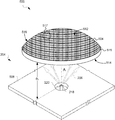
- FIG. 5 is a diagrammatic perspective view of a combustion system 500 , according to an embodiment.
- the combustion system 500 includes a nozzle 218 and a perforated flame holder 504 positioned within a combustion volume 204 .
- the perforated flame holder 504 of FIG. 5 is non-planar in shape.
- the perforated flame holder 504 includes a plurality of perforations 512 , an input face 514 , a perimeter wall 515 , an output face 516 , and a plurality of sections 517 .
- the input and output faces 514 , 516 of the perforated flame holder 504 are non-planar, and are rotationally symmetric to the plane that is perpendicular to the longitudinal axis of the nozzle 218 .
- Other non-planar embodiments of the flame holder are possible, and some of the other possible embodiments of a non-planar flame holder are disclosed in FIGS. 6-9 and the corresponding description.
- the input and output faces 514 , 516 of the perforated flame holder 504 include one of a number of non-planar shapes.
- the input and output faces 514 , 516 can have the same non-planar shapes, can have different non-planar shapes, or can have one non-planar shape and one planar shape, according to various embodiments.
- the input and output faces 514 , 516 can have the shape of a catenary arch, which can use pure compression for supporting the plurality of sections 517 over the nozzle 218 .
- the input and output faces 514 , 516 can alternatively be parabolic, spherical, a stepped shape, or another non-planar shape, configured to displace the middle or center of the perforated flame holder 504 to the same or to a greater distance from the nozzle 218 than a planar perforated flame holder.
- the input face 514 is concavely rotationally symmetric
- the output face 516 is convexly rotationally symmetric, according to one embodiment.
- the plurality of sections 517 can be configured in various shapes and sizes to form the perforated flame holder 504 .
- Each of the plurality of sections 517 is a tile, according to one embodiment.
- Each of the plurality of sections 517 can be cubical, rectangular, triangular, hexagonal, otherwise polygonal, or asymmetric so that the sections, e.g., tiles, naturally fit closely together over a spherical or arcuate surface.
- the plurality of sections 517 are cemented, adhered, or otherwise coupled together.
- the plurality of sections 517 can be formed directly in the curved shape, for example, by using a mold.
- the plurality of sections 517 can be sized to pass through a man-hole or other access into the combustion system 500 to facilitate replacement of damaged sections and to facilitate erection of the non-planar perforated flame holder 504 .
- the arch of the perforated flame holder 504 is determined by a departure angle of the output or input face from a plane that is perpendicular to the longitudinal axis of the nozzle 218 .
- the departure angle defines an angular displacement of an end of the non-planar flame holder from a center of the non-planar flame holder.
- the departure angle can be measured from a plane that is perpendicular to the longitudinal axis of the center of the non-planar flame holder.
- the departure angle can be approximately 45 degrees, so that one end of the perforated flame holder 504 to another sweeps through a total angle of approximately 90 degrees.
- the departure angle can be greater than or equal to 15 degree, greater than or equal to 30 degrees, or is some angle between 5-45 degrees.
- the arch of the input face 514 increases inward projections of thermal radiation 304 , to improve the operation of the perforated flame holder 504 , according to one embodiment.
- Most of the thermal radiation 304 comes from inside each of the plurality of perforations 512 , e.g., from the last centimeter of the length of the perforation.
- the non-planar shape (e.g., arch, parabola, spherical) of the input face 514 increases the view factor between the plurality of perforations 512 on opposite sides of the perforated flame holder 504 , more thermal radiation can be recycled/reused by the perforated flame holder 504 .
- one or more first perforations 512 of the input face 514 receive and transmit more thermal radiation 304 with one or more second perforations of the input face 514 .
- Inter-perforation radiation may help the non-planar perforated flame holder maintain a temperature that sustains the combustion reaction.
- the arch of the output face 516 increases the outward projections of thermal radiation 304 , to improve the operation of the combustion system 500 .
- the thermal radiation 304 can be directed towards a plurality of radiant section working fluid tubes 550 disposed proximate or adjacent to the perforated flame holder 504 .
- the outward projections of the thermal radiation 304 can heat the plurality of radiant section working fluid tubes, for use by one or more other systems.
- the combustion system 500 can include “water walls” that include tubes for circulating a working fluid in the walls, which is a typical configuration for water-tube boilers used in large applications such as power generation.
- the non-planar shape of the input and output faces 514 , 516 can provide mechanical robustness for the perforated flame holder 504 and can equalize fuel-air mixture flow rates across the input face of the perforated flame holder 504 .
- the non-planar shape of the input and output faces 514 , 516 reduces tensile loading on the input face by distributing the compressive loading of the output face through the perforated flame holder body, as discussed above.
- the non-planar shape of the flame holder may generally equalize the fuel flow rate to the input face by placing a central portion of a perforated flame holder 504 farther away from the fuel nozzle 218 and by placing a peripheral portion of the perforated flame holder 504 closer to the fuel nozzle 218 .
- the perforated flame holder 504 spans the combustion system 500 by a width W.
- the width W of the perforated flame holder 504 in one embodiment, is approximately 2 feet. In another embodiment, the width W of the perforated flame holder 504 is greater than or equal to 9 feet. Other lengths or diameters are also achievable, in accordance with various combustion system configurations.
- FIG. 6 is a diagrammatic perspective view of a combustion system 600 , according to an embodiment.
- the combustion system 600 includes a perforated flame holder 602 that is non-planar shaped, and which is positioned within the combustion volume 204 to sustain a combustion reaction.
- the perforated flame holder 602 includes an input face 604 , an outer wall 606 , and an output face 608 .
- the perforated flame holder 602 includes a plurality of perforations 512 that extend from the input face (or surface) 604 to the output face 608 of the flame holder 602 .
- the plurality of perforations 512 are rectangular, but can also be cylindrical, elliptical, or a polygonal prism, according to various embodiments.
- the perforated flame holder 602 is a two-dimensional arch that is lower at the walls 606 than at the center.
- the input face 604 is plane symmetric and concavely arcuate
- the output face 608 is plane symmetric and convexly arcuate, according to one embodiment.
- the sections 517 of the perforated flame holder 602 are substantially directly coupled to adjacent sections 517 .
- contact between adjacent sections 517 is limited to a single edge (and not a surface), and adjacent sections 517 are substantially coupled through an adhesive such as cement or ceramic material.
- the combustion system 600 illustrates a single nozzle 218 and a single perforated flame holder 602 .
- multiple perforated flame holders with the arcuate shape of flame holder 602 can be joined side-by-side or can be spaced apart side-by-side over the nozzle 218 to sustain a combustion reaction in the combustion system 600 .
- FIG. 7A is a diagrammatic perspective view of a perforated flame holder 700 that is non-planar shaped, according to another embodiment.
- the perforated flame holder 700 employs an axially symmetric stepped arch.
- the stepped arch includes a plurality of sections 517 , e.g., ceramic blocks, bricks, or tiles.
- the perforated flame holder 700 includes an input face 702 , an output face 704 , and a perimeter wall 706 , according to one embodiment.
- the input face 702 is concavely arched, and the output face 704 is convexly arched, according to one embodiment.
- the perforated flame holder 700 includes the plurality of perforations 512 that extend from the input face 702 to the output face 704 of the flame holder.
- the sections 517 of the perforated flame holder 700 are adhered or otherwise coupled together with overlapping portions of the sections 517 .
- FIG. 7B is a diagrammatic side sectional view of the perfor
- FIG. 7C is a diagrammatic plan view of a perforated flame holder 712 that is non-planar shaped, which uses hexagonal prism sections 517 rather than cubes, to provide a stepped arch, according to an embodiment.
- the perforated flame holder 712 includes a number of steps n, which include sections (or members) 517 having a distanced between flat sides of each section, e.g., tile.
- N (3 ⁇ 4)*[( D 2 /d ) ⁇ circumflex over ( ) ⁇ 2 ⁇ 1], (Equation 2) where D 2 is the diameter of the flame holder, (Equation 2) describes the total number of tiles N in terms of the distance d between flat sides of each section 517 and in terms of the diameter D 2 of the perforated flame holder 712 .
- FIG. 8 is a diagrammatic side sectional view of a perforated flame holder 800 that is non-planar shaped, which includes an downwardly arched input face 802 with respect to the fuel nozzle, according to one embodiment.
- the flame holder 800 includes an input face 802 , an output face 804 , and a perimeter wall 806 .
- the input face 802 is the input surface
- the output face 804 is the output surface of the perforated flame holder 800 .
- the input face 802 is convexly arcuate and plane symmetric
- the output face 804 is concavely arcuate and plane symmetric, according to one embodiment.
- the output face 804 is hotter than the input face 802 , during operation.
- the output face 804 is arched to inwardly project thermal radiation 304 to recycle or reuse the emitted thermal radiation 304 to maintain or sustain an operating temperature of the perforated flame holder 800 , according to one embodiment. Because the output face 804 reacts at a hotter temperature than the input face 802 , an inwardly arched output surface may be able to more effectively sustain the temperature of the perforated flame holder 800 than an inwardly arched input surface.
- the downwardly arched input surface may operate to reduce radiation directed toward a fuel nozzle (not shown) and instead direct radiation sideways, away from a fuel and oxidant stream.
- the inventors found the downwardly arched shape of the embodiment 800 to be associated with a reduced tendency toward “huffing,” described above in conjunction with FIGS. 2-4 .
- FIG. 9 is a diagrammatic side sectional view of a perforated flame holder 900 that is non-planar shaped, and which includes a curb or bump around the perimeter of the input face or the output face to reduce fuel losses, according to one embodiment.
- the flame holder 900 includes an input face 902 , an output face 904 , and a perimeter wall 906 .
- the perimeter wall 906 is thickened to extend beyond the length of the perforations 512 .
- the perforated flame holder 900 includes a curb 908 on the input face 902 to improve mechanical robustness of the perimeter wall 906 , according to one embodiment.
- the curb 908 can be a lip, bump, raised surface, a thickened edge, or other extension of part of the input face 902 that reinforces the structure of the perforated flame holder 906 , according to embodiments.
- FIG. 10 is a flow diagram of a method 1000 of operating a combustion system with a non-planar perforated flame holder, according to one embodiment.
- the method includes outputting fuel from a nozzle to generate a fuel-air mixture, according to one embodiment.
- the method includes receiving the fuel-air mixture with a non-planar perforated flame holder, according to one embodiment.
- the non-planar perforated flame holder includes a plurality of perforations that extend from an input face to an output face of the non-planar perforated flame holder.
- the method includes sustaining a combustion reaction of the fuel-air mixture, substantially within the plurality of perforations. Sustaining the combustion reaction can include maintaining an operating temperature of the non-planar perforated flame holder by recycling thermal radiation in between at least some of the plurality of perforations of the input face.
- the non-planar perforated flame holder can recycle the thermal radiation with a concavely shaped input face that provides non-zero view factors between the plurality of perforations at the input face.
- Sustaining the combustion reaction can include maintaining an operating temperature of the non-planar perforated flame holder by recycling thermal radiation in between at least some of the plurality of perforations at the output face.
- the non-planar perforated flame holder can recycle the thermal radiation with a concavely shaped output face that provides non-zero view factors between the plurality of perforations at the output face.
- Sustaining the combustion reaction may include heating one or more fluid systems positioned proximate to the non-planar perforated flame holder by directing thermal radiation from at least some of the plurality of perforations on the output face to the one or more fluid systems.
- the non-planar perforated flame holder can direct the thermal radiation with a convexly shaped output face that provides non-zero view factors between at least some of the plurality of perforations and the one or more fluid systems.
- Sustaining the combustion reaction can include equalizing a flow rate of the fuel-air mixture at the input face of the non-planar perforated flame holder by positioning a central portion of the non-planar perforated flame holder at a greater distance away from the fuel module then a peripheral portion of the non-planar perforated flame holder with the input face having an arcuate shape.
- the arcuate shape includes at least one of a parabolic arch, a spherical arch, a stepped arch, and a catenary arch.
Abstract
Description
N=3n(n−1)+1 (Equation 1)
describes the total number of tiles N in terms of the number of steps used in the
N=(¾)*[(D 2 /d){circumflex over ( )}2−1], (Equation 2)
where D 2 is the diameter of the flame holder, (Equation 2)
describes the total number of tiles N in terms of the distance d between flat sides of each
Claims (50)
Priority Applications (1)
| Application Number | Priority Date | Filing Date | Title |
|---|---|---|---|
| US16/137,339 US10823401B2 (en) | 2013-02-14 | 2018-09-20 | Burner system including a non-planar perforated flame holder |
Applications Claiming Priority (10)
| Application Number | Priority Date | Filing Date | Title |
|---|---|---|---|
| US201361765022P | 2013-02-14 | 2013-02-14 | |
| US201461931407P | 2014-01-24 | 2014-01-24 | |
| PCT/US2014/016632 WO2014127311A1 (en) | 2013-02-14 | 2014-02-14 | Fuel combustion system with a perforated reaction holder |
| PCT/US2014/016628 WO2014127307A1 (en) | 2013-02-14 | 2014-02-14 | Perforated flame holder and burner including a perforated flame holder |
| PCT/US2015/012843 WO2015112950A1 (en) | 2014-01-24 | 2015-01-26 | LOW NOx FIRE TUBE BOILER |
| PCT/US2015/016231 WO2015123696A1 (en) | 2013-02-14 | 2015-02-17 | Burner system including a non-planar perforated flame holder |
| US201514763271A | 2015-07-24 | 2015-07-24 | |
| US15/215,401 US10359213B2 (en) | 2013-02-14 | 2016-07-20 | Method for low NOx fire tube boiler |
| US15/236,862 US10119704B2 (en) | 2013-02-14 | 2016-08-15 | Burner system including a non-planar perforated flame holder |
| US16/137,339 US10823401B2 (en) | 2013-02-14 | 2018-09-20 | Burner system including a non-planar perforated flame holder |
Related Parent Applications (1)
| Application Number | Title | Priority Date | Filing Date |
|---|---|---|---|
| US15/236,862 Division US10119704B2 (en) | 2013-02-14 | 2016-08-15 | Burner system including a non-planar perforated flame holder |
Publications (2)
| Publication Number | Publication Date |
|---|---|
| US20190024887A1 US20190024887A1 (en) | 2019-01-24 |
| US10823401B2 true US10823401B2 (en) | 2020-11-03 |
Family
ID=58053363
Family Applications (2)
| Application Number | Title | Priority Date | Filing Date |
|---|---|---|---|
| US15/236,862 Expired - Fee Related US10119704B2 (en) | 2013-02-14 | 2016-08-15 | Burner system including a non-planar perforated flame holder |
| US16/137,339 Active 2034-07-24 US10823401B2 (en) | 2013-02-14 | 2018-09-20 | Burner system including a non-planar perforated flame holder |
Family Applications Before (1)
| Application Number | Title | Priority Date | Filing Date |
|---|---|---|---|
| US15/236,862 Expired - Fee Related US10119704B2 (en) | 2013-02-14 | 2016-08-15 | Burner system including a non-planar perforated flame holder |
Country Status (1)
| Country | Link |
|---|---|
| US (2) | US10119704B2 (en) |
Families Citing this family (14)
| Publication number | Priority date | Publication date | Assignee | Title |
|---|---|---|---|---|
| US9797595B2 (en) | 2013-02-14 | 2017-10-24 | Clearsign Combustion Corporation | Fuel combustion system with a perforated reaction holder |
| US10571124B2 (en) | 2013-02-14 | 2020-02-25 | Clearsign Combustion Corporation | Selectable dilution low NOx burner |
| AU2014324120A1 (en) * | 2013-09-23 | 2016-03-03 | Clearsign Combustion Corporation | Porous flame holder for low NOx combustion |
| WO2016133936A1 (en) | 2015-02-17 | 2016-08-25 | Clearsign Combustion Corporation | Prefabricated integrated combustion assemblies and methods of installing the same into a combustion system |
| WO2016134061A1 (en) | 2015-02-17 | 2016-08-25 | Clearsign Combustion Corporation | Perforated flame holder with adjustable fuel nozzle |
| US11473774B2 (en) | 2015-02-17 | 2022-10-18 | Clearsign Technologies Corporation | Methods of upgrading a conventional combustion system to include a perforated flame holder |
| CN112432166B (en) | 2016-01-13 | 2023-10-27 | 美一蓝技术公司 | Perforated flame holder with gaps between groups of tiles |
| US10551058B2 (en) | 2016-03-18 | 2020-02-04 | Clearsign Technologies Corporation | Multi-nozzle combustion assemblies including perforated flame holder, combustion systems including the combustion assemblies, and related methods |
| EP4317781A3 (en) | 2016-04-29 | 2024-04-03 | ClearSign Technologies Corporation | Burner system with discrete transverse flame stabilizers |
| US10514165B2 (en) | 2016-07-29 | 2019-12-24 | Clearsign Combustion Corporation | Perforated flame holder and system including protection from abrasive or corrosive fuel |
| US10539326B2 (en) | 2016-09-07 | 2020-01-21 | Clearsign Combustion Corporation | Duplex burner with velocity-compensated mesh and thickness |
| WO2018160884A1 (en) | 2017-03-03 | 2018-09-07 | Clearsign Combustion Corporation | Field installed perforated flame holder and method of assembly and installation |
| US11248795B2 (en) | 2018-03-09 | 2022-02-15 | Siemens Energy Global Gmbh & Co Kg | Finely distributed combustion system for a gas turbine engine |
| IT201800005549A1 (en) * | 2018-05-21 | 2019-11-21 | Heating appliance with combustible gas burner |
Citations (219)
| Publication number | Priority date | Publication date | Assignee | Title |
|---|---|---|---|---|
| US1377873A (en) | 1919-03-28 | 1921-05-10 | William H Chadick | Safety device for hydrocarbon-burners |
| US2095065A (en) | 1933-01-25 | 1937-10-05 | Joseph W Hays | Surface combustion process |
| US2604936A (en) | 1946-01-15 | 1952-07-29 | Metal Carbides Corp | Method and apparatus for controlling the generation and application of heat |
| US2635813A (en) | 1948-11-03 | 1953-04-21 | Pacific Flush Tank Co | Furnace and control system for gaseous and liquid fuel burners |
| US2828813A (en) | 1955-01-25 | 1958-04-01 | Artemas F Holden | Gas-fueled heating apparatus |
| US3008513A (en) | 1959-08-03 | 1961-11-14 | Artemas F Holden | Safety construction for luminous wall furnace |
| US3076605A (en) | 1959-08-03 | 1963-02-05 | Artemas F Holden | Control system for luminous wall furnace |
| US3306338A (en) | 1965-11-01 | 1967-02-28 | Exxon Research Engineering Co | Apparatus for the application of insulated a.c. fields to flares |
| US3324924A (en) | 1965-03-22 | 1967-06-13 | Du Pont | Radiant heating devices |
| US3439996A (en) | 1965-06-09 | 1969-04-22 | Solaronics Inc | Tile assembly for radiant gas burners |
| US3638621A (en) | 1969-08-26 | 1972-02-01 | Aqua Chem Inc | Combination fire and water tube boiler |
| US3663154A (en) | 1968-07-29 | 1972-05-16 | Bernzomatic Corp | Blow torch burner |
| US3847536A (en) | 1972-05-08 | 1974-11-12 | Antargaz | Radiant burner operating at high temperature |
| US3848573A (en) | 1972-11-03 | 1974-11-19 | J Phillips | Baffle means for heat exchanger, and method of fabrication thereof |
| US4021188A (en) | 1973-03-12 | 1977-05-03 | Tokyo Gas Company Limited | Burner configurations for staged combustion |
| US4081958A (en) | 1973-11-01 | 1978-04-04 | The Garrett Corporation | Low nitric oxide emission combustion system for gas turbines |
| US4111636A (en) | 1976-12-03 | 1978-09-05 | Lawrence P. Weinberger | Method and apparatus for reducing pollutant emissions while increasing efficiency of combustion |
| US4195596A (en) | 1976-08-02 | 1980-04-01 | The Dow Chemical Company | Combustion of halogenated hydrocarbons |
| US4397356A (en) | 1981-03-26 | 1983-08-09 | Retallick William B | High pressure combustor for generating steam downhole |
| US4408461A (en) | 1979-11-23 | 1983-10-11 | Bbc Brown, Boveri & Company Limited | Combustion chamber of a gas turbine with pre-mixing and pre-evaporation elements |
| US4413976A (en) | 1981-05-15 | 1983-11-08 | Southbend Escan Corporation | Igniter for a gas burner |
| US4443182A (en) | 1981-11-10 | 1984-04-17 | Hauck Manufacturing Company | Burner and method |
| US4483673A (en) | 1983-03-07 | 1984-11-20 | Matsushita Electric Industrial Co., Ltd. | Catalytic combustion arrangement |
| US4483340A (en) | 1980-10-20 | 1984-11-20 | Thomas J. Fogarty | Dilatation catheter |
| US4504218A (en) | 1981-02-03 | 1985-03-12 | Matsushita Electric Industrial Co., Ltd. | Ceramic burner plate |
| JPS6073242A (en) | 1983-09-30 | 1985-04-25 | Sanyo Electric Co Ltd | Combustion type warm air heater |
| US4519770A (en) | 1980-06-30 | 1985-05-28 | Alzeta Corp. | Firetube boiler heater system |
| US4588373A (en) | 1984-07-03 | 1986-05-13 | David Landau | Catalytic camping stove |
| US4624631A (en) | 1984-04-19 | 1986-11-25 | Toto Ltd. | Method and apparatus for gasifying and combusting liquid fuel |
| US4627388A (en) | 1985-07-22 | 1986-12-09 | The Dow Chemical Company | Combustion of halogenated hydrocarbons with heat recovery |
| US4643667A (en) | 1985-11-21 | 1987-02-17 | Institute Of Gas Technology | Non-catalytic porous-phase combustor |
| EP0223691A1 (en) | 1985-11-06 | 1987-05-27 | Gaz De France | Forced-draft gas burner |
| US4673349A (en) | 1984-12-20 | 1987-06-16 | Ngk Insulators, Ltd. | High temperature surface combustion burner |
| US4726767A (en) | 1985-04-27 | 1988-02-23 | Nakajima Dokosho Company Limited | Hot airstream generating device |
| US4773847A (en) | 1987-03-13 | 1988-09-27 | Tecogen, Inc. | Thermoelectric field burner |
| US4850862A (en) | 1988-05-03 | 1989-07-25 | Consolidated Natural Gas Service Company, Inc. | Porous body combustor/regenerator |
| US4906180A (en) | 1989-06-26 | 1990-03-06 | Solaronics | Tile retainer means |
| EP0478305A2 (en) | 1990-09-26 | 1992-04-01 | Hitachi, Ltd. | Combustor and combustion apparatus |
| US5235667A (en) | 1991-05-24 | 1993-08-10 | Casso-Solar Corp. | Heating method and assembly utilizing electric heating elements in conjunction with combustion |
| US5275552A (en) | 1992-03-27 | 1994-01-04 | John Zink Company, A Division Of Koch Engineering Co. Inc. | Low NOx gas burner apparatus and methods |
| JPH0626624A (en) | 1992-01-27 | 1994-02-04 | Seibu Gas Kk | Method and apparatus for promoting combustion in combustion device |
| US5326257A (en) | 1992-10-21 | 1994-07-05 | Maxon Corporation | Gas-fired radiant burner |
| US5375999A (en) | 1992-07-09 | 1994-12-27 | Nippon Oil Co., Ltd. | Catalyst combustor |
| WO1995000803A1 (en) | 1993-06-21 | 1995-01-05 | United Technologies Corporation | Heating unit with a high emissivity, porous ceramic flame holder |
| US5380192A (en) | 1993-07-26 | 1995-01-10 | Teledyne Industries, Inc. | High-reflectivity porous blue-flame gas burner |
| JPH0748136A (en) | 1993-08-09 | 1995-02-21 | Furukawa Electric Co Ltd:The | Flame-detection apparatus and apparatus and method for producing porous glass preform using the detection apparatus |
| JPH0783076A (en) | 1993-09-20 | 1995-03-28 | Hitachi Ltd | Combustion state grasping method and device to practice this method |
| US5409375A (en) | 1993-12-10 | 1995-04-25 | Selee Corporation | Radiant burner |
| US5431557A (en) | 1993-12-16 | 1995-07-11 | Teledyne Industries, Inc. | Low NOX gas combustion systems |
| US5441402A (en) | 1993-10-28 | 1995-08-15 | Gas Research Institute | Emission reduction |
| US5458484A (en) | 1994-05-16 | 1995-10-17 | Carrier Corporation | Pre-mix flame type burner |
| US5460512A (en) | 1993-05-27 | 1995-10-24 | Coen Company, Inc. | Vibration-resistant low NOx burner |
| US5511516A (en) | 1993-08-27 | 1996-04-30 | Sabh (U.S.) Water Heater Group, Inc. | Water heater with low NOx ceramic burner |
| US5641282A (en) | 1995-02-28 | 1997-06-24 | Gas Research Institute | Advanced radiant gas burner and method utilizing flame support rod structure |
| US5667374A (en) | 1992-10-16 | 1997-09-16 | Process Combustion Corporation | Premix single stage low NOx burner |
| US5718573A (en) | 1994-12-27 | 1998-02-17 | Carrier Corporation | Flashback resistant burner |
| US5749721A (en) | 1993-07-22 | 1998-05-12 | Gossler Thermal Ceramics Gmbh | Ceramic combustion support element for surface burners and process for producing the same |
| EP0844434A2 (en) | 1996-10-28 | 1998-05-27 | Teruo Arai | Burner |
| US5784889A (en) | 1995-11-17 | 1998-07-28 | Asea Brown Boveri Ag | Device for damping thermoacoustic pressure vibrations |
| US5890886A (en) | 1997-07-21 | 1999-04-06 | Sulzer Chemtech Ag | Burner for heating systems |
| US5899686A (en) | 1996-08-19 | 1999-05-04 | Gas Research Institute | Gas burner apparatus having a flame holder structure with a contoured surface |
| US5957682A (en) | 1996-09-04 | 1999-09-28 | Gordon-Piatt Energy Group, Inc. | Low NOx burner assembly |
| US5993192A (en) | 1997-09-16 | 1999-11-30 | Regents Of The University Of Minnesota | High heat flux catalytic radiant burner |
| US6095798A (en) | 1996-04-09 | 2000-08-01 | Toyota Jidosha Kabushiki Kaisha | Combustion apparatus |
| US6129545A (en) | 1996-11-26 | 2000-10-10 | Schott Glaswerke | Gas burner with pollution-reducing features |
| US6140658A (en) | 1973-02-16 | 2000-10-31 | Lockheed Martin Corporation | Combustion heated honeycomb mantle infrared radiation |
| US6149424A (en) | 1998-08-28 | 2000-11-21 | N. V. Bekaert S.A. | Undulated burner membrane |
| US6159001A (en) | 1995-06-07 | 2000-12-12 | Quantum Group, Inc. | Advanced emissive matrix combustion |
| US6210151B1 (en) | 1998-11-03 | 2001-04-03 | American Air Liquide | Self-cooled oxygen-fuel burner for use in high-temperature and high-particulate furnaces |
| US6270336B1 (en) | 1998-06-05 | 2001-08-07 | Matsushita Electric Industrial Co., Ltd. | Catalytic combustion system and combustion control method |
| US6287111B1 (en) | 1999-10-15 | 2001-09-11 | Wayne Gensler | Low NOx boilers, heaters, systems and methods |
| US20010046649A1 (en) | 2000-03-31 | 2001-11-29 | Schutz Wayne D. | Low pollution emission burner |
| CN2484481Y (en) | 2001-06-06 | 2002-04-03 | 浙江大学 | Gradual-change porous-medium burner |
| US6428312B1 (en) | 2000-05-10 | 2002-08-06 | Lochinvar Corporation | Resonance free burner |
| US20020155403A1 (en) | 2001-04-18 | 2002-10-24 | Timothy Griffin | Catalytically operating burner |
| US20020197574A1 (en) | 2001-06-25 | 2002-12-26 | Jones Andrew P. | Methods and apparatus for burning fuel with low NOx formation |
| US6499990B1 (en) | 2001-03-07 | 2002-12-31 | Zeeco, Inc. | Low NOx burner apparatus and method |
| US20030054313A1 (en) | 2001-09-19 | 2003-03-20 | David Rattner | Radiator element |
| US20040058290A1 (en) | 2001-06-28 | 2004-03-25 | Joshua Mauzey | Self-sustaining premixed pilot burner for liquid fuels |
| US20040081933A1 (en) | 2002-10-25 | 2004-04-29 | St. Charles Frank Kelley | Gas micro burner |
| US6752620B2 (en) | 2002-01-31 | 2004-06-22 | Air Products And Chemicals, Inc. | Large scale vortex devices for improved burner operation |
| US20040152028A1 (en) | 2003-02-05 | 2004-08-05 | Singh Prem C. | Flame-less infrared heater |
| US20040197719A1 (en) | 2002-12-06 | 2004-10-07 | I-Ping Chung | Compact low NOx gas burner apparatus and methods |
| US20050106520A1 (en) | 2003-09-05 | 2005-05-19 | Michael Cornwell | Device for stabilizing combustion in gas turbine engines |
| US20050208442A1 (en) | 2002-03-22 | 2005-09-22 | Rolf Heiligers | Fuel combustion device |
| US20060008755A1 (en) | 2003-08-05 | 2006-01-12 | Christoph Leinemann | Flame arrester |
| US6997701B2 (en) | 2001-03-26 | 2006-02-14 | Gvp Gesellschaft Zur Vermarketing Der Porenbrennertechnik Mbh | Burner for a gas and air mixture |
| US20060084017A1 (en) | 2004-10-15 | 2006-04-20 | William Huebner | Gas recuperative flameless thermal oxidizer |
| US20060141413A1 (en) | 2004-12-27 | 2006-06-29 | Masten James H | Burner plate and burner assembly |
| JP2006275482A (en) | 2005-03-30 | 2006-10-12 | Toho Gas Co Ltd | Burner |
| US7137808B2 (en) | 2001-08-01 | 2006-11-21 | Siemens Aktiengesellschaft | Method and device for influencing combustion processes involving combustibles |
| US20060292510A1 (en) | 2005-06-24 | 2006-12-28 | Chemical Physics Technologies, Inc. | Radiant gas burner |
| CN1950646A (en) | 2004-03-30 | 2007-04-18 | 冈安谦治 | Portable heat transmission device |
| US7243496B2 (en) | 2004-01-29 | 2007-07-17 | Siemens Power Generation, Inc. | Electric flame control using corona discharge enhancement |
| EP1916477A2 (en) | 2006-10-24 | 2008-04-30 | Air Products and Chemicals, Inc. | Low nox staged fuel injection burner for creating plug flow |
| US20080124666A1 (en) | 2006-10-24 | 2008-05-29 | Frank Stocker | Porous burner as well as a method for operating a porous burner |
| US20080131824A1 (en) | 2006-10-26 | 2008-06-05 | Deutsches Zentrum Fuer Luft- Und Raumfahrt E.V. | Burner device and method for injecting a mixture of fuel and oxidant into a combustion space |
| US7410288B1 (en) | 1998-12-24 | 2008-08-12 | Luminis Pty. Ltd. | Fluid mixing device |
| CN101294714A (en) | 2007-04-26 | 2008-10-29 | 株式会社日立制作所 | Combustor and a fuel supply method for the combustor |
| US20080268387A1 (en) | 2007-04-26 | 2008-10-30 | Takeo Saito | Combustion equipment and burner combustion method |
| US20100077731A1 (en) | 2005-06-22 | 2010-04-01 | Korea Institute Of Machinery And Materials | Burner for regeneration of diesel particulate filter |
| US20100126175A1 (en) | 2008-11-21 | 2010-05-27 | Korea Institute Of Industiral Technology | Fuel injection system and burner using the same |
| US20100178219A1 (en) | 2007-05-25 | 2010-07-15 | Xenophon Verykios | Highly heat integrated reformer for hydrogen production |
| DE102009028624A1 (en) | 2009-08-18 | 2011-02-24 | Sandvik Intellectual Property Ab | radiant burner |
| US20110076628A1 (en) | 2009-09-30 | 2011-03-31 | Hitachi, Ltd. | Combustor |
| US20110076629A1 (en) | 2009-09-29 | 2011-03-31 | Pawel Mosiewicz | LOW NOx INDIRECT FIRE BURNER |
| US20120064465A1 (en) | 2010-09-12 | 2012-03-15 | General Vortex Energy, Inc. | Combustion apparatus and methods |
| US20120116589A1 (en) | 2010-11-05 | 2012-05-10 | Clearstak Llc | Intelligently-controlled catalytic converter for biofuel-fired boiler |
| WO2012109499A1 (en) | 2011-02-09 | 2012-08-16 | Clearsign Combustion Corporation | System and method for flattening a flame |
| US20120231398A1 (en) | 2009-10-22 | 2012-09-13 | Gdf Suez | Radiating burner having enhanced performance and method for improving the performance of a radiating burner |
| US20130230810A1 (en) | 2012-03-01 | 2013-09-05 | Clearsign Combustion Corporation | Inertial electrode and system configured for electrodynamic interaction with a flame |
| US20130260321A1 (en) | 2012-02-22 | 2013-10-03 | Clearsign Combustion Corporation | Cooled electrode and burner system including a cooled electrode |
| WO2013181569A2 (en) | 2012-05-31 | 2013-12-05 | Clearsign Combustion Corporation | Burner with flame position electrode array |
| US20130323661A1 (en) | 2012-06-01 | 2013-12-05 | Clearsign Combustion Corporation | Long flame process heater |
| US20130336352A1 (en) | 2012-06-15 | 2013-12-19 | Clearsign Combustion Corporation | Electrically stabilized down-fired flame reactor |
| US20130333279A1 (en) | 2012-06-19 | 2013-12-19 | Clearsign Combustion Corporation | Flame enhancement for a rotary kiln |
| US20140051030A1 (en) | 2012-08-16 | 2014-02-20 | Clearsign Combustion Corporation | System and sacrificial electrode for applying electricity to a combustion reaction |
| US20140065558A1 (en) | 2012-07-24 | 2014-03-06 | Clearsign Combustion Corporation | Electrically stabilized burner |
| US20140080070A1 (en) | 2012-09-18 | 2014-03-20 | Clearsign Combustion Corporation | Close-coupled step-up voltage converter and electrode for a combustion system |
| EP2738460A1 (en) | 2012-11-29 | 2014-06-04 | Siemens Aktiengesellschaft | Combustion system of a flow engine |
| US20140162195A1 (en) | 2012-10-23 | 2014-06-12 | Clearsign Combustion Corporation | System for safe power loss for an electrodynamic burner |
| US20140162198A1 (en) | 2012-11-27 | 2014-06-12 | Clearsign Combustion Corporation | Multistage ionizer for a combustion system |
| US20140162197A1 (en) | 2012-11-27 | 2014-06-12 | Clearsign Combustion Corporation | Multijet burner with charge interaction |
| US20140170577A1 (en) | 2012-12-11 | 2014-06-19 | Clearsign Combustion Corporation | Burner having a cast dielectric electrode holder |
| US20140170575A1 (en) | 2012-12-14 | 2014-06-19 | Clearsign Combustion Corporation | Ionizer for a combustion system, including foam electrode structure |
| US20140170571A1 (en) | 2012-12-13 | 2014-06-19 | Clearsign Combustion Corporation | Combustion control electrode assemblies, systems, and methods of manufacturing and use |
| US20140170569A1 (en) | 2012-12-12 | 2014-06-19 | Clearsign Combustion Corporation | Electrically controlled combustion system with contact electrostatic charge generation |
| US20140170576A1 (en) | 2012-12-12 | 2014-06-19 | Clearsign Combustion Corporation | Contained flame flare stack |
| US20140186778A1 (en) | 2012-12-28 | 2014-07-03 | Clearsign Combustion Corporation | Wirelessly powered electrodynamic combustion system |
| US20140196368A1 (en) | 2013-01-16 | 2014-07-17 | Clearsign Combustion Corporation | Gasifier having at least one charge transfer electrode and methods of use thereof |
| US20140196369A1 (en) | 2013-01-16 | 2014-07-17 | Clearsign Combustion Corporation | Gasifier configured to electrodynamically agitate charged chemical species in a reaction region and related methods |
| US20140212820A1 (en) | 2013-01-30 | 2014-07-31 | Clearsign Combustion Corporation | Burner system including at least one coanda surface and electrodynamic control system, and related methods |
| US20140208758A1 (en) | 2011-12-30 | 2014-07-31 | Clearsign Combustion Corporation | Gas turbine with extended turbine blade stream adhesion |
| US20140216401A1 (en) | 2013-02-04 | 2014-08-07 | Clearsign Combustion Corporation | Combustion system configured to generate and charge at least one series of fuel pulses, and related methods |
| US20140227645A1 (en) | 2013-02-14 | 2014-08-14 | Clearsign Combustion Corporation | Burner systems configured to control at least one geometric characteristic of a flame and related methods |
| US20140227649A1 (en) | 2013-02-12 | 2014-08-14 | Clearsign Combustion Corporation | Method and apparatus for delivering a high voltage to a flame-coupled electrode |
| US20140227646A1 (en) | 2013-02-13 | 2014-08-14 | Clearsign Combustion Corporation | Combustion system including at least one fuel flow equalizer |
| US20140248566A1 (en) | 2013-03-04 | 2014-09-04 | Clearsign Combustion Corporation | Combustion system including one or more flame anchoring electrodes and related methods |
| US20140255855A1 (en) | 2013-03-05 | 2014-09-11 | Clearsign Combustion Corporation | Dynamic flame control |
| US20140255856A1 (en) | 2013-03-06 | 2014-09-11 | Clearsign Combustion Corporation | Flame control in the buoyancy-dominated fluid dynamics region |
| US20140272730A1 (en) | 2013-03-12 | 2014-09-18 | Clearsign Combustion Corporation | Active magnetic control of a flame |
| US20140272731A1 (en) | 2013-03-15 | 2014-09-18 | Clearsign Combustion Corporation | Flame control in the momentum-dominated fluid dynamics region |
| US20140287368A1 (en) | 2013-03-23 | 2014-09-25 | Clearsign Combustion Corporation | Premixed flame location control |
| US20140295094A1 (en) | 2013-03-26 | 2014-10-02 | Clearsign Combustion Corporation | Combustion deposition systems and methods of use |
| US20140295360A1 (en) | 2010-04-01 | 2014-10-02 | Clearsign Combustion Corporation | Electrodynamic control in a burner system |
| US8851882B2 (en) | 2009-04-03 | 2014-10-07 | Clearsign Combustion Corporation | System and apparatus for applying an electric field to a combustion volume |
| US20140335460A1 (en) | 2013-05-13 | 2014-11-13 | Clearsign Combustion Corporation | Electrically enhanced combustion control system with multiple power sources and method of operation |
| US8911699B2 (en) | 2012-08-14 | 2014-12-16 | Clearsign Combustion Corporation | Charge-induced selective reduction of nitrogen |
| WO2015017084A1 (en) | 2013-07-30 | 2015-02-05 | Clearsign Combustion Corporation | Combustor having a nonmetallic body with external electrodes |
| US20150079524A1 (en) | 2012-10-23 | 2015-03-19 | Clearsign Combustion Corporation | LIFTED FLAME LOW NOx BURNER WITH FLAME POSITION CONTROL |
| WO2015038245A1 (en) | 2013-09-13 | 2015-03-19 | Clearsign Combustion Corporation | Transient control of a combustion reaction |
| WO2015042566A1 (en) | 2013-09-23 | 2015-03-26 | Clearsign Combustion Corporation | Control of combustion reaction physical extent |
| WO2015042614A1 (en) | 2013-09-23 | 2015-03-26 | Clearsign Combustion Corporation | Burner system employing multiple perforated flame holders, and method of operation |
| WO2015042615A1 (en) | 2013-09-23 | 2015-03-26 | Clearsign Combustion Corporation | Horizontally fired burner with a perforated flame holder |
| WO2015051136A1 (en) | 2013-10-02 | 2015-04-09 | Clearsign Combustion Corporation | Electrical and thermal insulation for a combustion system |
| US20150104748A1 (en) | 2013-10-14 | 2015-04-16 | Clearsign Combustion Corporation | Electrodynamic combustion control (ecc) technology for biomass and coal systems |
| WO2015054323A1 (en) | 2013-10-07 | 2015-04-16 | Clearsign Combustion Corporation | Pre-mixed fuel burner with perforated flame holder |
| US20150107260A1 (en) | 2012-04-30 | 2015-04-23 | Clearsign Combustion Corporation | Gas turbine and gas turbine afterburner |
| WO2015061760A1 (en) | 2013-10-24 | 2015-04-30 | Clearsign Combustion Corporation | System and combustion reaction holder configured to transfer heat from a combustion reaction to a fluid |
| WO2015070188A1 (en) | 2013-11-08 | 2015-05-14 | Clearsign Combustion Corporation | Combustion system with flame location actuation |
| US20150147706A1 (en) | 2012-11-27 | 2015-05-28 | Clearsign Combustion Corporation | Electrodynamic burner with a flame ionizer |
| US20150147704A1 (en) | 2012-11-27 | 2015-05-28 | Clearsign Combustion Corporation | Charged ion flows for combustion control |
| WO2015089306A1 (en) | 2013-12-11 | 2015-06-18 | Clearsign Combustion Corporation | Process material electrode for combustion control |
| WO2015103436A1 (en) | 2013-12-31 | 2015-07-09 | Clearsign Combustion Corporation | Method and apparatus for extending flammability limits in a combustion reaction |
| WO2015112950A1 (en) | 2014-01-24 | 2015-07-30 | Clearsign Combustion Corporation | LOW NOx FIRE TUBE BOILER |
| US20150219333A1 (en) | 2012-08-27 | 2015-08-06 | Clearsign Combustion Corporation | Electrodynamic combustion system with variable gain electrodes |
| US20150226424A1 (en) | 2013-12-14 | 2015-08-13 | Clearsign Combustion Corporation | Method and apparatus for shaping a flame |
| WO2015123683A1 (en) | 2014-02-14 | 2015-08-20 | Clearsign Combustion Corporation | Application of an electric field to a combustion reaction supported by a perforated flame holder |
| WO2015123381A1 (en) | 2014-02-14 | 2015-08-20 | Clearsign Combustion Corporation | Down-fired burner with a perforated flame holder |
| WO2015123694A1 (en) | 2013-02-14 | 2015-08-20 | Clearsign Combustion Corporation | Method for operating a combustion system including a perforated flame holder |
| WO2015123701A1 (en) | 2014-02-14 | 2015-08-20 | Clearsign Combustion Corporation | Electrically heated burner |
| US20150241057A1 (en) | 2012-09-10 | 2015-08-27 | Clearsign Combustion Corporation | Electrodynamic combustion control with current limiting electrical element |
| US20150276211A1 (en) | 2013-03-18 | 2015-10-01 | Clearsign Combustion Corporation | Flame control in the flame-holding region |
| US9151549B2 (en) | 2010-01-13 | 2015-10-06 | Clearsign Combustion Corporation | Method and apparatus for electrical control of heat transfer |
| US20150338089A1 (en) | 2012-06-29 | 2015-11-26 | Clearsign Combustion Corporation | Combustion system with a corona electrode |
| US20150345781A1 (en) | 2012-12-26 | 2015-12-03 | Clearsign Combustion Corporation | Combustion system with a grid switching electrode |
| US20150345780A1 (en) | 2012-12-21 | 2015-12-03 | Clearsign Combustion Corporation | Electrical combustion control system including a complementary electrode pair |
| US9209654B2 (en) | 2011-12-30 | 2015-12-08 | Clearsign Combustion Corporation | Method and apparatus for enhancing flame radiation |
| US20150362178A1 (en) | 2013-02-14 | 2015-12-17 | Clearsign Combustion Corporation | SELECTABLE DILUTION LOW NOx BURNER |
| US20150362177A1 (en) | 2014-06-11 | 2015-12-17 | Clearsign Combustion Corporation | Flame position control electrodes |
| US20150369476A1 (en) | 2014-06-23 | 2015-12-24 | Clearsign Combustion Corporation | Combustion systems and methods for reducing combustion temperature |
| US20160003471A1 (en) | 2014-07-07 | 2016-01-07 | Clearsign Combustion Corporation | Burner with a perforated flame holder support structure |
| WO2016003883A1 (en) | 2014-06-30 | 2016-01-07 | Clearsign Combustion Corporation | Low inertia power supply for applying voltage to an electrode coupled to a flame |
| WO2016007564A1 (en) | 2014-07-07 | 2016-01-14 | Clearsign Combustion Corporation | Burner system including a moveable perforated flame holder |
| US20160018103A1 (en) | 2013-03-27 | 2016-01-21 | Clearsign Combustion Corporation | Electrically controlled combustion fluid flow |
| US20160025374A1 (en) | 2014-07-28 | 2016-01-28 | Clearsign Combustion Corporation | Water heater with perforated flame holder, and method of operation |
| US20160025380A1 (en) | 2014-07-28 | 2016-01-28 | Clearsign Combustion Corporation | Water heater with a variable-output burner including a perforated flame holder and method of operation |
| WO2016018610A1 (en) | 2014-07-30 | 2016-02-04 | Clearsign Combustion Corporation | Asymmetrical unipolar flame ionizer using a step-up transformer |
| US20160033125A1 (en) | 2013-03-28 | 2016-02-04 | Clearsign Combustion Corporation | Battery-powered high-voltage converter circuit with electrical isolation and mechanism for charging the battery |
| US20160040872A1 (en) | 2013-03-20 | 2016-02-11 | Clearsign Combustion Corporation | Electrically stabilized swirl-stabilized burner |
| US20160047542A1 (en) | 2014-08-15 | 2016-02-18 | Clearsign Combustion Corporation | Adaptor for providing electrical combustion control to a burner |
| US20160046524A1 (en) | 2014-08-13 | 2016-02-18 | Clearsign Combustion Corporation | Perforated burner for a rotary kiln |
| US9267680B2 (en) | 2012-03-27 | 2016-02-23 | Clearsign Combustion Corporation | Multiple fuel combustion system and method |
| US9284886B2 (en) | 2011-12-30 | 2016-03-15 | Clearsign Combustion Corporation | Gas turbine with Coulombic thermal protection |
| US9289780B2 (en) | 2012-03-27 | 2016-03-22 | Clearsign Combustion Corporation | Electrically-driven particulate agglomeration in a combustion system |
| US20160091200A1 (en) | 2013-05-10 | 2016-03-31 | Clearsign Combustion Corporation | Combustion system and method for electrically assisted start-up |
| US9310077B2 (en) | 2012-07-31 | 2016-04-12 | Clearsign Combustion Corporation | Acoustic control of an electrodynamic combustion system |
| US20160109118A1 (en) | 2014-10-15 | 2016-04-21 | Clearsign Combustion Corporation | Current gated electrode for applying an electric field to a flame |
| US20160123576A1 (en) | 2011-12-30 | 2016-05-05 | Clearsign Combustion Corporation | Method and apparatus for enhancing flame radiation in a coal-burner retrofit |
| US20160123577A1 (en) | 2014-11-03 | 2016-05-05 | Clearsign Combustion Corporation | Solid fuel system with electrodynamic combustion control |
| US20160138800A1 (en) | 2013-07-29 | 2016-05-19 | Clearsign Combustion Corporation | Combustion-powered electrodynamic combustion system |
| US20160138799A1 (en) | 2014-11-13 | 2016-05-19 | Clearsign Combustion Corporation | Burner or boiler electrical discharge control |
| US9366427B2 (en) | 2012-03-27 | 2016-06-14 | Clearsign Combustion Corporation | Solid fuel burner with electrodynamic homogenization |
| US9371994B2 (en) | 2013-03-08 | 2016-06-21 | Clearsign Combustion Corporation | Method for Electrically-driven classification of combustion particles |
| US9377195B2 (en) | 2012-03-01 | 2016-06-28 | Clearsign Combustion Corporation | Inertial electrode and system configured for electrodynamic interaction with a voltage-biased flame |
| US9377189B2 (en) | 2013-02-21 | 2016-06-28 | Clearsign Combustion Corporation | Methods for operating an oscillating combustor with pulsed charger |
| WO2016105489A2 (en) | 2014-12-24 | 2016-06-30 | Clearsign Combustion Corporation | Flame holders with fuel and oxidant recirculation, combustion systems including such flame holders, and related methods |
| US20160215974A1 (en) | 2013-10-04 | 2016-07-28 | Clearsign Combustion Corporation | Ionizer for a combustion system |
| US20160238277A1 (en) | 2015-02-17 | 2016-08-18 | Clearsign Combustion Corporation | Box heater including a perforated flame holder |
| US20160238240A1 (en) | 2015-02-17 | 2016-08-18 | Clearsign Combustion Corporation | Duct burner including a perforated flame holder |
| US20160238242A1 (en) | 2015-02-18 | 2016-08-18 | Clearsign Combustion Corporation | Burner with a perforated flame holder support structure |
| US20160238318A1 (en) | 2015-02-17 | 2016-08-18 | Clearsign Combustion Corporation | Tunnel burner including a perforated flame holder |
| WO2016134068A1 (en) | 2015-02-17 | 2016-08-25 | Clearsign Combustion Corporation | Burner system with a perforated flame holder and a plurality of fuel sources |
| WO2016133936A1 (en) | 2015-02-17 | 2016-08-25 | Clearsign Combustion Corporation | Prefabricated integrated combustion assemblies and methods of installing the same into a combustion system |
| WO2016133934A1 (en) | 2015-02-17 | 2016-08-25 | Clearsign Combustion Corporation | Methods of upgrading a conventional combustion system to include a perforated flame holder |
| WO2016134061A1 (en) | 2015-02-17 | 2016-08-25 | Clearsign Combustion Corporation | Perforated flame holder with adjustable fuel nozzle |
| US20160245509A1 (en) | 2015-02-18 | 2016-08-25 | Clearsign Combustion Corporation | Flare stack with perforated flame holder |
| WO2016141362A1 (en) | 2015-03-04 | 2016-09-09 | Clearsign Combustion Corporation | BURNER WITH REDUCED NOx OUTPUT FROM A NITROGEN-CONTAINING FUEL |
| US20160298840A1 (en) | 2013-02-14 | 2016-10-13 | Clearsign Combustion Corporation | Horizontally fired burner with a perforated flame holder |
-
2016
- 2016-08-15 US US15/236,862 patent/US10119704B2/en not_active Expired - Fee Related
-
2018
- 2018-09-20 US US16/137,339 patent/US10823401B2/en active Active
Patent Citations (250)
| Publication number | Priority date | Publication date | Assignee | Title |
|---|---|---|---|---|
| US1377873A (en) | 1919-03-28 | 1921-05-10 | William H Chadick | Safety device for hydrocarbon-burners |
| US2095065A (en) | 1933-01-25 | 1937-10-05 | Joseph W Hays | Surface combustion process |
| US2604936A (en) | 1946-01-15 | 1952-07-29 | Metal Carbides Corp | Method and apparatus for controlling the generation and application of heat |
| US2635813A (en) | 1948-11-03 | 1953-04-21 | Pacific Flush Tank Co | Furnace and control system for gaseous and liquid fuel burners |
| US2828813A (en) | 1955-01-25 | 1958-04-01 | Artemas F Holden | Gas-fueled heating apparatus |
| US3008513A (en) | 1959-08-03 | 1961-11-14 | Artemas F Holden | Safety construction for luminous wall furnace |
| US3076605A (en) | 1959-08-03 | 1963-02-05 | Artemas F Holden | Control system for luminous wall furnace |
| US3324924A (en) | 1965-03-22 | 1967-06-13 | Du Pont | Radiant heating devices |
| US3439996A (en) | 1965-06-09 | 1969-04-22 | Solaronics Inc | Tile assembly for radiant gas burners |
| US3306338A (en) | 1965-11-01 | 1967-02-28 | Exxon Research Engineering Co | Apparatus for the application of insulated a.c. fields to flares |
| US3663154A (en) | 1968-07-29 | 1972-05-16 | Bernzomatic Corp | Blow torch burner |
| US3638621A (en) | 1969-08-26 | 1972-02-01 | Aqua Chem Inc | Combination fire and water tube boiler |
| US3847536A (en) | 1972-05-08 | 1974-11-12 | Antargaz | Radiant burner operating at high temperature |
| US3848573A (en) | 1972-11-03 | 1974-11-19 | J Phillips | Baffle means for heat exchanger, and method of fabrication thereof |
| US6140658A (en) | 1973-02-16 | 2000-10-31 | Lockheed Martin Corporation | Combustion heated honeycomb mantle infrared radiation |
| US4021188A (en) | 1973-03-12 | 1977-05-03 | Tokyo Gas Company Limited | Burner configurations for staged combustion |
| US4081958A (en) | 1973-11-01 | 1978-04-04 | The Garrett Corporation | Low nitric oxide emission combustion system for gas turbines |
| US4195596A (en) | 1976-08-02 | 1980-04-01 | The Dow Chemical Company | Combustion of halogenated hydrocarbons |
| US4111636A (en) | 1976-12-03 | 1978-09-05 | Lawrence P. Weinberger | Method and apparatus for reducing pollutant emissions while increasing efficiency of combustion |
| US4408461A (en) | 1979-11-23 | 1983-10-11 | Bbc Brown, Boveri & Company Limited | Combustion chamber of a gas turbine with pre-mixing and pre-evaporation elements |
| US4519770A (en) | 1980-06-30 | 1985-05-28 | Alzeta Corp. | Firetube boiler heater system |
| US4483340A (en) | 1980-10-20 | 1984-11-20 | Thomas J. Fogarty | Dilatation catheter |
| US4504218A (en) | 1981-02-03 | 1985-03-12 | Matsushita Electric Industrial Co., Ltd. | Ceramic burner plate |
| US4397356A (en) | 1981-03-26 | 1983-08-09 | Retallick William B | High pressure combustor for generating steam downhole |
| US4413976A (en) | 1981-05-15 | 1983-11-08 | Southbend Escan Corporation | Igniter for a gas burner |
| US4443182A (en) | 1981-11-10 | 1984-04-17 | Hauck Manufacturing Company | Burner and method |
| US4483673A (en) | 1983-03-07 | 1984-11-20 | Matsushita Electric Industrial Co., Ltd. | Catalytic combustion arrangement |
| JPS6073242A (en) | 1983-09-30 | 1985-04-25 | Sanyo Electric Co Ltd | Combustion type warm air heater |
| US4624631A (en) | 1984-04-19 | 1986-11-25 | Toto Ltd. | Method and apparatus for gasifying and combusting liquid fuel |
| US4588373A (en) | 1984-07-03 | 1986-05-13 | David Landau | Catalytic camping stove |
| US4673349A (en) | 1984-12-20 | 1987-06-16 | Ngk Insulators, Ltd. | High temperature surface combustion burner |
| US4726767A (en) | 1985-04-27 | 1988-02-23 | Nakajima Dokosho Company Limited | Hot airstream generating device |
| US4627388A (en) | 1985-07-22 | 1986-12-09 | The Dow Chemical Company | Combustion of halogenated hydrocarbons with heat recovery |
| EP0223691A1 (en) | 1985-11-06 | 1987-05-27 | Gaz De France | Forced-draft gas burner |
| US4752213A (en) | 1985-11-06 | 1988-06-21 | Gaz De France | Forced-air gas burner |
| US4643667A (en) | 1985-11-21 | 1987-02-17 | Institute Of Gas Technology | Non-catalytic porous-phase combustor |
| US4773847A (en) | 1987-03-13 | 1988-09-27 | Tecogen, Inc. | Thermoelectric field burner |
| US4850862A (en) | 1988-05-03 | 1989-07-25 | Consolidated Natural Gas Service Company, Inc. | Porous body combustor/regenerator |
| US4906180A (en) | 1989-06-26 | 1990-03-06 | Solaronics | Tile retainer means |
| EP0478305A2 (en) | 1990-09-26 | 1992-04-01 | Hitachi, Ltd. | Combustor and combustion apparatus |
| US5235667A (en) | 1991-05-24 | 1993-08-10 | Casso-Solar Corp. | Heating method and assembly utilizing electric heating elements in conjunction with combustion |
| JPH0626624A (en) | 1992-01-27 | 1994-02-04 | Seibu Gas Kk | Method and apparatus for promoting combustion in combustion device |
| US5275552A (en) | 1992-03-27 | 1994-01-04 | John Zink Company, A Division Of Koch Engineering Co. Inc. | Low NOx gas burner apparatus and methods |
| US5375999A (en) | 1992-07-09 | 1994-12-27 | Nippon Oil Co., Ltd. | Catalyst combustor |
| US5667374A (en) | 1992-10-16 | 1997-09-16 | Process Combustion Corporation | Premix single stage low NOx burner |
| US5326257A (en) | 1992-10-21 | 1994-07-05 | Maxon Corporation | Gas-fired radiant burner |
| US5460512A (en) | 1993-05-27 | 1995-10-24 | Coen Company, Inc. | Vibration-resistant low NOx burner |
| WO1995000803A1 (en) | 1993-06-21 | 1995-01-05 | United Technologies Corporation | Heating unit with a high emissivity, porous ceramic flame holder |
| US5749721A (en) | 1993-07-22 | 1998-05-12 | Gossler Thermal Ceramics Gmbh | Ceramic combustion support element for surface burners and process for producing the same |
| US5380192A (en) | 1993-07-26 | 1995-01-10 | Teledyne Industries, Inc. | High-reflectivity porous blue-flame gas burner |
| JPH0748136A (en) | 1993-08-09 | 1995-02-21 | Furukawa Electric Co Ltd:The | Flame-detection apparatus and apparatus and method for producing porous glass preform using the detection apparatus |
| US5511516A (en) | 1993-08-27 | 1996-04-30 | Sabh (U.S.) Water Heater Group, Inc. | Water heater with low NOx ceramic burner |
| JPH0783076A (en) | 1993-09-20 | 1995-03-28 | Hitachi Ltd | Combustion state grasping method and device to practice this method |
| US5441402A (en) | 1993-10-28 | 1995-08-15 | Gas Research Institute | Emission reduction |
| US5409375A (en) | 1993-12-10 | 1995-04-25 | Selee Corporation | Radiant burner |
| US5431557A (en) | 1993-12-16 | 1995-07-11 | Teledyne Industries, Inc. | Low NOX gas combustion systems |
| US5458484A (en) | 1994-05-16 | 1995-10-17 | Carrier Corporation | Pre-mix flame type burner |
| US5718573A (en) | 1994-12-27 | 1998-02-17 | Carrier Corporation | Flashback resistant burner |
| US5641282A (en) | 1995-02-28 | 1997-06-24 | Gas Research Institute | Advanced radiant gas burner and method utilizing flame support rod structure |
| US6159001A (en) | 1995-06-07 | 2000-12-12 | Quantum Group, Inc. | Advanced emissive matrix combustion |
| US5784889A (en) | 1995-11-17 | 1998-07-28 | Asea Brown Boveri Ag | Device for damping thermoacoustic pressure vibrations |
| US6095798A (en) | 1996-04-09 | 2000-08-01 | Toyota Jidosha Kabushiki Kaisha | Combustion apparatus |
| US5899686A (en) | 1996-08-19 | 1999-05-04 | Gas Research Institute | Gas burner apparatus having a flame holder structure with a contoured surface |
| US5957682A (en) | 1996-09-04 | 1999-09-28 | Gordon-Piatt Energy Group, Inc. | Low NOx burner assembly |
| EP0844434A2 (en) | 1996-10-28 | 1998-05-27 | Teruo Arai | Burner |
| US6129545A (en) | 1996-11-26 | 2000-10-10 | Schott Glaswerke | Gas burner with pollution-reducing features |
| US5890886A (en) | 1997-07-21 | 1999-04-06 | Sulzer Chemtech Ag | Burner for heating systems |
| US5993192A (en) | 1997-09-16 | 1999-11-30 | Regents Of The University Of Minnesota | High heat flux catalytic radiant burner |
| US6270336B1 (en) | 1998-06-05 | 2001-08-07 | Matsushita Electric Industrial Co., Ltd. | Catalytic combustion system and combustion control method |
| US6149424A (en) | 1998-08-28 | 2000-11-21 | N. V. Bekaert S.A. | Undulated burner membrane |
| US6210151B1 (en) | 1998-11-03 | 2001-04-03 | American Air Liquide | Self-cooled oxygen-fuel burner for use in high-temperature and high-particulate furnaces |
| US7410288B1 (en) | 1998-12-24 | 2008-08-12 | Luminis Pty. Ltd. | Fluid mixing device |
| US6287111B1 (en) | 1999-10-15 | 2001-09-11 | Wayne Gensler | Low NOx boilers, heaters, systems and methods |
| US20010046649A1 (en) | 2000-03-31 | 2001-11-29 | Schutz Wayne D. | Low pollution emission burner |
| US6428312B1 (en) | 2000-05-10 | 2002-08-06 | Lochinvar Corporation | Resonance free burner |
| US6499990B1 (en) | 2001-03-07 | 2002-12-31 | Zeeco, Inc. | Low NOx burner apparatus and method |
| US6997701B2 (en) | 2001-03-26 | 2006-02-14 | Gvp Gesellschaft Zur Vermarketing Der Porenbrennertechnik Mbh | Burner for a gas and air mixture |
| US20020155403A1 (en) | 2001-04-18 | 2002-10-24 | Timothy Griffin | Catalytically operating burner |
| CN2484481Y (en) | 2001-06-06 | 2002-04-03 | 浙江大学 | Gradual-change porous-medium burner |
| US20020197574A1 (en) | 2001-06-25 | 2002-12-26 | Jones Andrew P. | Methods and apparatus for burning fuel with low NOx formation |
| US20040058290A1 (en) | 2001-06-28 | 2004-03-25 | Joshua Mauzey | Self-sustaining premixed pilot burner for liquid fuels |
| US7137808B2 (en) | 2001-08-01 | 2006-11-21 | Siemens Aktiengesellschaft | Method and device for influencing combustion processes involving combustibles |
| US20030054313A1 (en) | 2001-09-19 | 2003-03-20 | David Rattner | Radiator element |
| US6752620B2 (en) | 2002-01-31 | 2004-06-22 | Air Products And Chemicals, Inc. | Large scale vortex devices for improved burner operation |
| US20050208442A1 (en) | 2002-03-22 | 2005-09-22 | Rolf Heiligers | Fuel combustion device |
| US20040081933A1 (en) | 2002-10-25 | 2004-04-29 | St. Charles Frank Kelley | Gas micro burner |
| US20040197719A1 (en) | 2002-12-06 | 2004-10-07 | I-Ping Chung | Compact low NOx gas burner apparatus and methods |
| US20040152028A1 (en) | 2003-02-05 | 2004-08-05 | Singh Prem C. | Flame-less infrared heater |
| US20060008755A1 (en) | 2003-08-05 | 2006-01-12 | Christoph Leinemann | Flame arrester |
| US20050106520A1 (en) | 2003-09-05 | 2005-05-19 | Michael Cornwell | Device for stabilizing combustion in gas turbine engines |
| US7243496B2 (en) | 2004-01-29 | 2007-07-17 | Siemens Power Generation, Inc. | Electric flame control using corona discharge enhancement |
| CN1950646A (en) | 2004-03-30 | 2007-04-18 | 冈安谦治 | Portable heat transmission device |
| US20060084017A1 (en) | 2004-10-15 | 2006-04-20 | William Huebner | Gas recuperative flameless thermal oxidizer |
| US20060141413A1 (en) | 2004-12-27 | 2006-06-29 | Masten James H | Burner plate and burner assembly |
| JP2006275482A (en) | 2005-03-30 | 2006-10-12 | Toho Gas Co Ltd | Burner |
| US20100077731A1 (en) | 2005-06-22 | 2010-04-01 | Korea Institute Of Machinery And Materials | Burner for regeneration of diesel particulate filter |
| US20060292510A1 (en) | 2005-06-24 | 2006-12-28 | Chemical Physics Technologies, Inc. | Radiant gas burner |
| US20080124666A1 (en) | 2006-10-24 | 2008-05-29 | Frank Stocker | Porous burner as well as a method for operating a porous burner |
| EP1916477A2 (en) | 2006-10-24 | 2008-04-30 | Air Products and Chemicals, Inc. | Low nox staged fuel injection burner for creating plug flow |
| US20080131824A1 (en) | 2006-10-26 | 2008-06-05 | Deutsches Zentrum Fuer Luft- Und Raumfahrt E.V. | Burner device and method for injecting a mixture of fuel and oxidant into a combustion space |
| CN101294714A (en) | 2007-04-26 | 2008-10-29 | 株式会社日立制作所 | Combustor and a fuel supply method for the combustor |
| US20080268387A1 (en) | 2007-04-26 | 2008-10-30 | Takeo Saito | Combustion equipment and burner combustion method |
| US20100178219A1 (en) | 2007-05-25 | 2010-07-15 | Xenophon Verykios | Highly heat integrated reformer for hydrogen production |
| US20100126175A1 (en) | 2008-11-21 | 2010-05-27 | Korea Institute Of Industiral Technology | Fuel injection system and burner using the same |
| US8851882B2 (en) | 2009-04-03 | 2014-10-07 | Clearsign Combustion Corporation | System and apparatus for applying an electric field to a combustion volume |
| DE102009028624A1 (en) | 2009-08-18 | 2011-02-24 | Sandvik Intellectual Property Ab | radiant burner |
| US20120164590A1 (en) | 2009-08-18 | 2012-06-28 | Alexander Mach | Radiant Burner |
| US20110076629A1 (en) | 2009-09-29 | 2011-03-31 | Pawel Mosiewicz | LOW NOx INDIRECT FIRE BURNER |
| US20110076628A1 (en) | 2009-09-30 | 2011-03-31 | Hitachi, Ltd. | Combustor |
| US20120231398A1 (en) | 2009-10-22 | 2012-09-13 | Gdf Suez | Radiating burner having enhanced performance and method for improving the performance of a radiating burner |
| US9151549B2 (en) | 2010-01-13 | 2015-10-06 | Clearsign Combustion Corporation | Method and apparatus for electrical control of heat transfer |
| US20140295360A1 (en) | 2010-04-01 | 2014-10-02 | Clearsign Combustion Corporation | Electrodynamic control in a burner system |
| US20120064465A1 (en) | 2010-09-12 | 2012-03-15 | General Vortex Energy, Inc. | Combustion apparatus and methods |
| US20120116589A1 (en) | 2010-11-05 | 2012-05-10 | Clearstak Llc | Intelligently-controlled catalytic converter for biofuel-fired boiler |
| WO2012109499A1 (en) | 2011-02-09 | 2012-08-16 | Clearsign Combustion Corporation | System and method for flattening a flame |
| US8881535B2 (en) | 2011-02-09 | 2014-11-11 | Clearsign Combustion Corporation | Electric field control of two or more responses in a combustion system |
| US9243800B2 (en) | 2011-02-09 | 2016-01-26 | Clearsign Combustion Corporation | Apparatus for electrodynamically driving a charged gas or charged particles entrained in a gas |
| US20140208758A1 (en) | 2011-12-30 | 2014-07-31 | Clearsign Combustion Corporation | Gas turbine with extended turbine blade stream adhesion |
| US9209654B2 (en) | 2011-12-30 | 2015-12-08 | Clearsign Combustion Corporation | Method and apparatus for enhancing flame radiation |
| US9284886B2 (en) | 2011-12-30 | 2016-03-15 | Clearsign Combustion Corporation | Gas turbine with Coulombic thermal protection |
| US20160123576A1 (en) | 2011-12-30 | 2016-05-05 | Clearsign Combustion Corporation | Method and apparatus for enhancing flame radiation in a coal-burner retrofit |
| US20130260321A1 (en) | 2012-02-22 | 2013-10-03 | Clearsign Combustion Corporation | Cooled electrode and burner system including a cooled electrode |
| US9377195B2 (en) | 2012-03-01 | 2016-06-28 | Clearsign Combustion Corporation | Inertial electrode and system configured for electrodynamic interaction with a voltage-biased flame |
| US20130230810A1 (en) | 2012-03-01 | 2013-09-05 | Clearsign Combustion Corporation | Inertial electrode and system configured for electrodynamic interaction with a flame |
| US9267680B2 (en) | 2012-03-27 | 2016-02-23 | Clearsign Combustion Corporation | Multiple fuel combustion system and method |
| US9366427B2 (en) | 2012-03-27 | 2016-06-14 | Clearsign Combustion Corporation | Solid fuel burner with electrodynamic homogenization |
| US9289780B2 (en) | 2012-03-27 | 2016-03-22 | Clearsign Combustion Corporation | Electrically-driven particulate agglomeration in a combustion system |
| US20150107260A1 (en) | 2012-04-30 | 2015-04-23 | Clearsign Combustion Corporation | Gas turbine and gas turbine afterburner |
| US20150121890A1 (en) | 2012-04-30 | 2015-05-07 | Clearsign Combustion Corporation | High velocity combustor |
| US20150118629A1 (en) | 2012-05-31 | 2015-04-30 | Clearsign Combustion Corporation | Burner with flame position electrode array |
| US20150140498A1 (en) | 2012-05-31 | 2015-05-21 | Clearsign Combustion Corporation | LOW NOx BURNER AND METHOD OF OPERATING A LOW NOx BURNER |
| US20150147705A1 (en) | 2012-05-31 | 2015-05-28 | Clearsign Combustion Corporation | LOW NOx LIFTED FLAME BURNER |
| WO2013181569A2 (en) | 2012-05-31 | 2013-12-05 | Clearsign Combustion Corporation | Burner with flame position electrode array |
| US20130323655A1 (en) | 2012-05-31 | 2013-12-05 | Clearsign Combustion Corporation | Burner system with anti-flashback electrode |
| US20130323661A1 (en) | 2012-06-01 | 2013-12-05 | Clearsign Combustion Corporation | Long flame process heater |
| US20130336352A1 (en) | 2012-06-15 | 2013-12-19 | Clearsign Combustion Corporation | Electrically stabilized down-fired flame reactor |
| US20130333279A1 (en) | 2012-06-19 | 2013-12-19 | Clearsign Combustion Corporation | Flame enhancement for a rotary kiln |
| US20150338089A1 (en) | 2012-06-29 | 2015-11-26 | Clearsign Combustion Corporation | Combustion system with a corona electrode |
| US20140065558A1 (en) | 2012-07-24 | 2014-03-06 | Clearsign Combustion Corporation | Electrically stabilized burner |
| US9310077B2 (en) | 2012-07-31 | 2016-04-12 | Clearsign Combustion Corporation | Acoustic control of an electrodynamic combustion system |
| US8911699B2 (en) | 2012-08-14 | 2014-12-16 | Clearsign Combustion Corporation | Charge-induced selective reduction of nitrogen |
| US20140051030A1 (en) | 2012-08-16 | 2014-02-20 | Clearsign Combustion Corporation | System and sacrificial electrode for applying electricity to a combustion reaction |
| US20150219333A1 (en) | 2012-08-27 | 2015-08-06 | Clearsign Combustion Corporation | Electrodynamic combustion system with variable gain electrodes |
| US20150241057A1 (en) | 2012-09-10 | 2015-08-27 | Clearsign Combustion Corporation | Electrodynamic combustion control with current limiting electrical element |
| US20140080070A1 (en) | 2012-09-18 | 2014-03-20 | Clearsign Combustion Corporation | Close-coupled step-up voltage converter and electrode for a combustion system |
| US20160161115A1 (en) | 2012-10-23 | 2016-06-09 | Clearsign Combustion Corporation | Burner with electrodynamic flame position control system |
| US20150079524A1 (en) | 2012-10-23 | 2015-03-19 | Clearsign Combustion Corporation | LIFTED FLAME LOW NOx BURNER WITH FLAME POSITION CONTROL |
| US20140162195A1 (en) | 2012-10-23 | 2014-06-12 | Clearsign Combustion Corporation | System for safe power loss for an electrodynamic burner |
| US20140162198A1 (en) | 2012-11-27 | 2014-06-12 | Clearsign Combustion Corporation | Multistage ionizer for a combustion system |
| US20140162197A1 (en) | 2012-11-27 | 2014-06-12 | Clearsign Combustion Corporation | Multijet burner with charge interaction |
| US20150147706A1 (en) | 2012-11-27 | 2015-05-28 | Clearsign Combustion Corporation | Electrodynamic burner with a flame ionizer |
| US20150147704A1 (en) | 2012-11-27 | 2015-05-28 | Clearsign Combustion Corporation | Charged ion flows for combustion control |
| US20140162196A1 (en) | 2012-11-27 | 2014-06-12 | Clearsign Combustion Corporation | Precombustion ionization |
| EP2738460A1 (en) | 2012-11-29 | 2014-06-04 | Siemens Aktiengesellschaft | Combustion system of a flow engine |
| US20140170577A1 (en) | 2012-12-11 | 2014-06-19 | Clearsign Combustion Corporation | Burner having a cast dielectric electrode holder |
| US20140170569A1 (en) | 2012-12-12 | 2014-06-19 | Clearsign Combustion Corporation | Electrically controlled combustion system with contact electrostatic charge generation |
| US20140170576A1 (en) | 2012-12-12 | 2014-06-19 | Clearsign Combustion Corporation | Contained flame flare stack |
| US20140170571A1 (en) | 2012-12-13 | 2014-06-19 | Clearsign Combustion Corporation | Combustion control electrode assemblies, systems, and methods of manufacturing and use |
| US20140170575A1 (en) | 2012-12-14 | 2014-06-19 | Clearsign Combustion Corporation | Ionizer for a combustion system, including foam electrode structure |
| US20150345780A1 (en) | 2012-12-21 | 2015-12-03 | Clearsign Combustion Corporation | Electrical combustion control system including a complementary electrode pair |
| US20150345781A1 (en) | 2012-12-26 | 2015-12-03 | Clearsign Combustion Corporation | Combustion system with a grid switching electrode |
| US20140186778A1 (en) | 2012-12-28 | 2014-07-03 | Clearsign Combustion Corporation | Wirelessly powered electrodynamic combustion system |
| US20140196369A1 (en) | 2013-01-16 | 2014-07-17 | Clearsign Combustion Corporation | Gasifier configured to electrodynamically agitate charged chemical species in a reaction region and related methods |
| US20140196368A1 (en) | 2013-01-16 | 2014-07-17 | Clearsign Combustion Corporation | Gasifier having at least one charge transfer electrode and methods of use thereof |
| US20140212820A1 (en) | 2013-01-30 | 2014-07-31 | Clearsign Combustion Corporation | Burner system including at least one coanda surface and electrodynamic control system, and related methods |
| US20140216401A1 (en) | 2013-02-04 | 2014-08-07 | Clearsign Combustion Corporation | Combustion system configured to generate and charge at least one series of fuel pulses, and related methods |
| US20140227649A1 (en) | 2013-02-12 | 2014-08-14 | Clearsign Combustion Corporation | Method and apparatus for delivering a high voltage to a flame-coupled electrode |
| US20140227646A1 (en) | 2013-02-13 | 2014-08-14 | Clearsign Combustion Corporation | Combustion system including at least one fuel flow equalizer |
| US20150285491A1 (en) | 2013-02-14 | 2015-10-08 | Clearsign Combustion Corporation | Burner with a series of fuel gas ejectors and a perforated flame holder |
| US20160298840A1 (en) | 2013-02-14 | 2016-10-13 | Clearsign Combustion Corporation | Horizontally fired burner with a perforated flame holder |
| US9377190B2 (en) | 2013-02-14 | 2016-06-28 | Clearsign Combustion Corporation | Burner with a perforated flame holder and pre-heat apparatus |
| US20160025333A1 (en) | 2013-02-14 | 2016-01-28 | Clearsign Combustion Corporation | Perforated flame holder and burner including a perforated flame holder |
| US20150316261A1 (en) | 2013-02-14 | 2015-11-05 | Clearsign Combustion Corporation | Fuel combustion system with a perforated reaction holder |
| US20150362178A1 (en) | 2013-02-14 | 2015-12-17 | Clearsign Combustion Corporation | SELECTABLE DILUTION LOW NOx BURNER |
| US20150369477A1 (en) | 2013-02-14 | 2015-12-24 | Clearsign Combustion Corporation | Startup method and mechanism for a burner having a perforated flame holder |
| US20140227645A1 (en) | 2013-02-14 | 2014-08-14 | Clearsign Combustion Corporation | Burner systems configured to control at least one geometric characteristic of a flame and related methods |
| US20150276213A1 (en) | 2013-02-14 | 2015-10-01 | Clearsign Combustion Corporation | Method for flame location transition from a start-up location to a perforated flame holder |
| US20150276212A1 (en) | 2013-02-14 | 2015-10-01 | Clearsign Combustion Corporation | Burner with a perforated flame holder and pre-heat apparatus |
| US9447965B2 (en) | 2013-02-14 | 2016-09-20 | Clearsign Comubstion Corporation | Burner with a perforated reaction holder and heating apparatus |
| WO2015123694A1 (en) | 2013-02-14 | 2015-08-20 | Clearsign Combustion Corporation | Method for operating a combustion system including a perforated flame holder |
| WO2015123696A1 (en) | 2013-02-14 | 2015-08-20 | Clearsign Combustion Corporation | Burner system including a non-planar perforated flame holder |
| WO2015123670A1 (en) | 2013-02-14 | 2015-08-20 | Clearsign Combustion Corporation | High output porous tile burner |
| US20150276217A1 (en) | 2013-02-14 | 2015-10-01 | Clearsign Combustion Corporation | Burner with a fuel nozzle and a perforated flame holder separated by an entrainment distance |
| WO2015123149A2 (en) | 2013-02-14 | 2015-08-20 | Clearsign Combustion Corporation | Burners with flame control and positioning, and related methods |
| US9388981B2 (en) | 2013-02-14 | 2016-07-12 | Clearsign Combustion Corporation | Method for flame location transition from a start-up location to a perforated flame holder |
| US20150276220A1 (en) | 2013-02-14 | 2015-10-01 | Clearsign Combustion Corporation | Burner with a perforated reaction holder and heating apparatus |
| US9377188B2 (en) | 2013-02-21 | 2016-06-28 | Clearsign Combustion Corporation | Oscillating combustor |
| US9377189B2 (en) | 2013-02-21 | 2016-06-28 | Clearsign Combustion Corporation | Methods for operating an oscillating combustor with pulsed charger |
| US20140248566A1 (en) | 2013-03-04 | 2014-09-04 | Clearsign Combustion Corporation | Combustion system including one or more flame anchoring electrodes and related methods |
| US20140255855A1 (en) | 2013-03-05 | 2014-09-11 | Clearsign Combustion Corporation | Dynamic flame control |
| US20140255856A1 (en) | 2013-03-06 | 2014-09-11 | Clearsign Combustion Corporation | Flame control in the buoyancy-dominated fluid dynamics region |
| US9371994B2 (en) | 2013-03-08 | 2016-06-21 | Clearsign Combustion Corporation | Method for Electrically-driven classification of combustion particles |
| US20140272730A1 (en) | 2013-03-12 | 2014-09-18 | Clearsign Combustion Corporation | Active magnetic control of a flame |
| US20140272731A1 (en) | 2013-03-15 | 2014-09-18 | Clearsign Combustion Corporation | Flame control in the momentum-dominated fluid dynamics region |
| US20150276211A1 (en) | 2013-03-18 | 2015-10-01 | Clearsign Combustion Corporation | Flame control in the flame-holding region |
| US20160040872A1 (en) | 2013-03-20 | 2016-02-11 | Clearsign Combustion Corporation | Electrically stabilized swirl-stabilized burner |
| US20140287368A1 (en) | 2013-03-23 | 2014-09-25 | Clearsign Combustion Corporation | Premixed flame location control |
| US20140295094A1 (en) | 2013-03-26 | 2014-10-02 | Clearsign Combustion Corporation | Combustion deposition systems and methods of use |
| US20160018103A1 (en) | 2013-03-27 | 2016-01-21 | Clearsign Combustion Corporation | Electrically controlled combustion fluid flow |
| US20160033125A1 (en) | 2013-03-28 | 2016-02-04 | Clearsign Combustion Corporation | Battery-powered high-voltage converter circuit with electrical isolation and mechanism for charging the battery |
| US20160091200A1 (en) | 2013-05-10 | 2016-03-31 | Clearsign Combustion Corporation | Combustion system and method for electrically assisted start-up |
| US20140335460A1 (en) | 2013-05-13 | 2014-11-13 | Clearsign Combustion Corporation | Electrically enhanced combustion control system with multiple power sources and method of operation |
| US20160138800A1 (en) | 2013-07-29 | 2016-05-19 | Clearsign Combustion Corporation | Combustion-powered electrodynamic combustion system |
| US20160161110A1 (en) | 2013-07-30 | 2016-06-09 | Clearsign Combustion Corporation | Combustor having a nonmetallic body with external electrodes |
| WO2015017084A1 (en) | 2013-07-30 | 2015-02-05 | Clearsign Combustion Corporation | Combustor having a nonmetallic body with external electrodes |
| WO2015038245A1 (en) | 2013-09-13 | 2015-03-19 | Clearsign Combustion Corporation | Transient control of a combustion reaction |
| WO2015042615A1 (en) | 2013-09-23 | 2015-03-26 | Clearsign Combustion Corporation | Horizontally fired burner with a perforated flame holder |
| WO2015042614A1 (en) | 2013-09-23 | 2015-03-26 | Clearsign Combustion Corporation | Burner system employing multiple perforated flame holders, and method of operation |
| WO2015042566A1 (en) | 2013-09-23 | 2015-03-26 | Clearsign Combustion Corporation | Control of combustion reaction physical extent |
| US20150330625A1 (en) | 2013-09-23 | 2015-11-19 | Clearsign Combustion Corporation | POROUS FLAME HOLDER FOR LOW NOx COMBUSTION |
| US20160230984A1 (en) | 2013-09-23 | 2016-08-11 | Clearsign Combustion Corporation | Burner system employing multiple perforated flame holders, and method of operation |
| WO2015051136A1 (en) | 2013-10-02 | 2015-04-09 | Clearsign Combustion Corporation | Electrical and thermal insulation for a combustion system |
| US20160215974A1 (en) | 2013-10-04 | 2016-07-28 | Clearsign Combustion Corporation | Ionizer for a combustion system |
| WO2015054323A1 (en) | 2013-10-07 | 2015-04-16 | Clearsign Combustion Corporation | Pre-mixed fuel burner with perforated flame holder |
| WO2015057740A1 (en) | 2013-10-14 | 2015-04-23 | Clearsign Combustion Corporation | Flame visualization control for electrodynamic combustion control |
| US20160305660A1 (en) | 2013-10-14 | 2016-10-20 | Clearsign Combustion Corporation | Flame visualization control for a burner including a perforated flame holder |
| US20150104748A1 (en) | 2013-10-14 | 2015-04-16 | Clearsign Combustion Corporation | Electrodynamic combustion control (ecc) technology for biomass and coal systems |
| WO2015061760A1 (en) | 2013-10-24 | 2015-04-30 | Clearsign Combustion Corporation | System and combustion reaction holder configured to transfer heat from a combustion reaction to a fluid |
| WO2015070188A1 (en) | 2013-11-08 | 2015-05-14 | Clearsign Combustion Corporation | Combustion system with flame location actuation |
| WO2015089306A1 (en) | 2013-12-11 | 2015-06-18 | Clearsign Combustion Corporation | Process material electrode for combustion control |
| US20150226424A1 (en) | 2013-12-14 | 2015-08-13 | Clearsign Combustion Corporation | Method and apparatus for shaping a flame |
| WO2015103436A1 (en) | 2013-12-31 | 2015-07-09 | Clearsign Combustion Corporation | Method and apparatus for extending flammability limits in a combustion reaction |
| WO2015112950A1 (en) | 2014-01-24 | 2015-07-30 | Clearsign Combustion Corporation | LOW NOx FIRE TUBE BOILER |
| WO2015123683A1 (en) | 2014-02-14 | 2015-08-20 | Clearsign Combustion Corporation | Application of an electric field to a combustion reaction supported by a perforated flame holder |
| WO2015123381A1 (en) | 2014-02-14 | 2015-08-20 | Clearsign Combustion Corporation | Down-fired burner with a perforated flame holder |
| WO2015123701A1 (en) | 2014-02-14 | 2015-08-20 | Clearsign Combustion Corporation | Electrically heated burner |
| US20150362177A1 (en) | 2014-06-11 | 2015-12-17 | Clearsign Combustion Corporation | Flame position control electrodes |
| US20150369476A1 (en) | 2014-06-23 | 2015-12-24 | Clearsign Combustion Corporation | Combustion systems and methods for reducing combustion temperature |
| WO2016003883A1 (en) | 2014-06-30 | 2016-01-07 | Clearsign Combustion Corporation | Low inertia power supply for applying voltage to an electrode coupled to a flame |
| US20160003471A1 (en) | 2014-07-07 | 2016-01-07 | Clearsign Combustion Corporation | Burner with a perforated flame holder support structure |
| WO2016007564A1 (en) | 2014-07-07 | 2016-01-14 | Clearsign Combustion Corporation | Burner system including a moveable perforated flame holder |
| US20160025374A1 (en) | 2014-07-28 | 2016-01-28 | Clearsign Combustion Corporation | Water heater with perforated flame holder, and method of operation |
| US20160025380A1 (en) | 2014-07-28 | 2016-01-28 | Clearsign Combustion Corporation | Water heater with a variable-output burner including a perforated flame holder and method of operation |
| WO2016018610A1 (en) | 2014-07-30 | 2016-02-04 | Clearsign Combustion Corporation | Asymmetrical unipolar flame ionizer using a step-up transformer |
| US20160046524A1 (en) | 2014-08-13 | 2016-02-18 | Clearsign Combustion Corporation | Perforated burner for a rotary kiln |
| US20160047542A1 (en) | 2014-08-15 | 2016-02-18 | Clearsign Combustion Corporation | Adaptor for providing electrical combustion control to a burner |
| US20160109118A1 (en) | 2014-10-15 | 2016-04-21 | Clearsign Combustion Corporation | Current gated electrode for applying an electric field to a flame |
| US20160123577A1 (en) | 2014-11-03 | 2016-05-05 | Clearsign Combustion Corporation | Solid fuel system with electrodynamic combustion control |
| US20160138799A1 (en) | 2014-11-13 | 2016-05-19 | Clearsign Combustion Corporation | Burner or boiler electrical discharge control |
| WO2016105489A2 (en) | 2014-12-24 | 2016-06-30 | Clearsign Combustion Corporation | Flame holders with fuel and oxidant recirculation, combustion systems including such flame holders, and related methods |
| US20160238318A1 (en) | 2015-02-17 | 2016-08-18 | Clearsign Combustion Corporation | Tunnel burner including a perforated flame holder |
| WO2016134068A1 (en) | 2015-02-17 | 2016-08-25 | Clearsign Combustion Corporation | Burner system with a perforated flame holder and a plurality of fuel sources |
| WO2016133936A1 (en) | 2015-02-17 | 2016-08-25 | Clearsign Combustion Corporation | Prefabricated integrated combustion assemblies and methods of installing the same into a combustion system |
| WO2016133934A1 (en) | 2015-02-17 | 2016-08-25 | Clearsign Combustion Corporation | Methods of upgrading a conventional combustion system to include a perforated flame holder |
| WO2016134061A1 (en) | 2015-02-17 | 2016-08-25 | Clearsign Combustion Corporation | Perforated flame holder with adjustable fuel nozzle |
| US20160238240A1 (en) | 2015-02-17 | 2016-08-18 | Clearsign Combustion Corporation | Duct burner including a perforated flame holder |
| US20160238277A1 (en) | 2015-02-17 | 2016-08-18 | Clearsign Combustion Corporation | Box heater including a perforated flame holder |
| US20160245509A1 (en) | 2015-02-18 | 2016-08-25 | Clearsign Combustion Corporation | Flare stack with perforated flame holder |
| US20160238242A1 (en) | 2015-02-18 | 2016-08-18 | Clearsign Combustion Corporation | Burner with a perforated flame holder support structure |
| WO2016141362A1 (en) | 2015-03-04 | 2016-09-09 | Clearsign Combustion Corporation | BURNER WITH REDUCED NOx OUTPUT FROM A NITROGEN-CONTAINING FUEL |
Non-Patent Citations (13)
| Title |
|---|
| Arnold Schwarzenegger, A Low NOx Porous Ceramics Burner Performance Study, California Energy Commission Public Interest Energy Research Program, Dec. 2007, San Diego State University Foundation. |
| EPO Extended Search Report and Search Opinion of EP Application No. 14752076.1 dated Oct. 27, 2016. |
| EPO Extended Search Report and Search Opinion of EP Application No. 15739931.2 dated Sep. 21, 2017. |
| Fric, Thomas F., "Effects of Fuel-Air Unmixedness on NOx Emissions," Sep.-Oct. 1993. Journal of Propulsion and Power, vol. 9, No. 5, pp. 708-713. |
| Howell, J.R., et al., "Combustion of Hydrocarbon Fuels Within Porous Inert Media", Dept. of Mechanical Engineering, The University of Texas at Austin. Prog. Energy Comb. Sci., 1996, vol. 22, pp. 121-145. |
| M. Abdul Mujeebu et al., "Applications of Porous Media Combustion Technology-A Review." Applied Energy 86, 2009, pp. 1365-1375. |
| M. Abdul Mujeebu et al., "Applications of Porous Media Combustion Technology—A Review." Applied Energy 86, 2009, pp. 1365-1375. |
| PCT International Search Report and Written Opinion of PCT Application No. PCT/US2014/016628 dated May 27, 2014. |
| PCT International Search Report and Written Opinion of PCT Application No. PCT/US2014/016632 dated May 26, 2014. |
| PCT International Search Report and Written Opinion of PCT Application No. PCT/US2015/012843 dated May 7, 2015. |
| PCT International Search Report and Written Opinion of PCT Application No. PCT/US2015/016231 dated May 26, 2015. |
| PCT International Search Report and Written Opinion of PCT/US2014/016622 dated May 27, 2014. |
| PCT International Search Report and Written Opinion of PCT/US2014/057075 dated Jan. 14, 2015. |
Also Published As
| Publication number | Publication date |
|---|---|
| US10119704B2 (en) | 2018-11-06 |
| US20170038063A1 (en) | 2017-02-09 |
| US20190024887A1 (en) | 2019-01-24 |
Similar Documents
| Publication | Publication Date | Title |
|---|---|---|
| US10823401B2 (en) | Burner system including a non-planar perforated flame holder | |
| US10386062B2 (en) | Method for operating a combustion system including a perforated flame holder | |
| US11248786B2 (en) | Method for a perforated flame holder with adjustable fuel nozzle | |
| WO2015123696A1 (en) | Burner system including a non-planar perforated flame holder | |
| US10125983B2 (en) | High output porous tile burner | |
| US11953199B2 (en) | Burner and burner system with flange mount | |
| US10571124B2 (en) | Selectable dilution low NOx burner | |
| US20160238242A1 (en) | Burner with a perforated flame holder support structure | |
| US20160238277A1 (en) | Box heater including a perforated flame holder | |
| US20170350591A1 (en) | Burner system with a perforated flame holder and a plurality of fuel sources | |
| US10088153B2 (en) | Radiant wall burner including perforated flame holders | |
| US20160245509A1 (en) | Flare stack with perforated flame holder | |
| US20160238240A1 (en) | Duct burner including a perforated flame holder | |
| US11415316B2 (en) | Combustion system with perforated flame holder and swirl stabilized preheating flame | |
| US20190049107A1 (en) | High output porous tile burner | |
| WO2018236762A1 (en) | Flame holder burner pilot | |
| US11906160B2 (en) | Combustion system including a mixing tube and a flame holder | |
| US20190390854A1 (en) | Method for operating a combustion system including a perforated flame holder | |
| US20200003413A1 (en) | Furnace including perforated and bluff body flame holder for enhanced stability and turndown | |
| US20200340664A9 (en) | Ultra low emissions firetube boiler burner | |
| US20210063086A1 (en) | Burner system including a plurality of perforated flame holders | |
| US20230115032A1 (en) | Ultra low emissions firetube boiler burner |
Legal Events
| Date | Code | Title | Description |
|---|---|---|---|
| FEPP | Fee payment procedure |
Free format text: ENTITY STATUS SET TO UNDISCOUNTED (ORIGINAL EVENT CODE: BIG.); ENTITY STATUS OF PATENT OWNER: SMALL ENTITY |
|
| FEPP | Fee payment procedure |
Free format text: ENTITY STATUS SET TO SMALL (ORIGINAL EVENT CODE: SMAL); ENTITY STATUS OF PATENT OWNER: SMALL ENTITY |
|
| STPP | Information on status: patent application and granting procedure in general |
Free format text: DOCKETED NEW CASE - READY FOR EXAMINATION |
|
| AS | Assignment |
Owner name: CLEARSIGN COMBUSTION CORPORATION, WASHINGTON Free format text: ASSIGNMENT OF ASSIGNORS INTEREST;ASSIGNORS:COLANNINO, JOSEPH;KARKOW, DOUGLAS W.;DANSIE, JAMES K.;AND OTHERS;SIGNING DATES FROM 20160928 TO 20161025;REEL/FRAME:052199/0793 |
|
| AS | Assignment |
Owner name: CLEARSIGN TECHNOLOGIES CORPORATION, WASHINGTON Free format text: CHANGE OF NAME;ASSIGNOR:CLEARSIGN COMBUSTION CORPORATION;REEL/FRAME:052268/0365 Effective date: 20191106 |
|
| STPP | Information on status: patent application and granting procedure in general |
Free format text: NON FINAL ACTION MAILED |
|
| STPP | Information on status: patent application and granting procedure in general |
Free format text: RESPONSE TO NON-FINAL OFFICE ACTION ENTERED AND FORWARDED TO EXAMINER |
|
| STPP | Information on status: patent application and granting procedure in general |
Free format text: PUBLICATIONS -- ISSUE FEE PAYMENT VERIFIED |
|
| STCF | Information on status: patent grant |
Free format text: PATENTED CASE |
|
| AS | Assignment |
Owner name: CLEARSIGN TECHNOLOGIES CORPORATION, OKLAHOMA Free format text: CORRECTIVE ASSIGNMENT TO CORRECT THE NAME CHANGE FROM CLEARSIGN COMBUSTION CORPORATION, SEATTLE, WA TO CLEARSIGN TECHNOLOGIES CORPORATION, TULSA, OK.. PREVIOUSLY RECORDED AT REEL: 052268 FRAME: 0365. ASSIGNOR(S) HEREBY CONFIRMS THE CHANGE OF NAME;ASSIGNOR:CLEARSIGN COMBUSTION CORPORATION;REEL/FRAME:061176/0107 Effective date: 20191106 |