US10821561B2 - Exothermic welding cup and exothermic welding capsule - Google Patents
Exothermic welding cup and exothermic welding capsule Download PDFInfo
- Publication number
- US10821561B2 US10821561B2 US16/481,967 US201816481967A US10821561B2 US 10821561 B2 US10821561 B2 US 10821561B2 US 201816481967 A US201816481967 A US 201816481967A US 10821561 B2 US10821561 B2 US 10821561B2
- Authority
- US
- United States
- Prior art keywords
- cup
- disposed
- cover
- welding
- exothermic welding
- Prior art date
- Legal status (The legal status is an assumption and is not a legal conclusion. Google has not performed a legal analysis and makes no representation as to the accuracy of the status listed.)
- Active
Links
- 238000003466 welding Methods 0.000 title claims abstract description 100
- 239000002775 capsule Substances 0.000 title claims abstract description 17
- 238000010438 heat treatment Methods 0.000 claims abstract description 75
- 238000005538 encapsulation Methods 0.000 claims abstract description 49
- 239000000843 powder Substances 0.000 claims abstract description 36
- 238000003825 pressing Methods 0.000 claims description 30
- RYGMFSIKBFXOCR-UHFFFAOYSA-N Copper Chemical compound [Cu] RYGMFSIKBFXOCR-UHFFFAOYSA-N 0.000 claims description 9
- 230000004907 flux Effects 0.000 claims description 8
- 229910052802 copper Inorganic materials 0.000 claims description 7
- 239000010949 copper Substances 0.000 claims description 7
- VYPSYNLAJGMNEJ-UHFFFAOYSA-N Silicium dioxide Chemical compound O=[Si]=O VYPSYNLAJGMNEJ-UHFFFAOYSA-N 0.000 claims description 3
- 239000000741 silica gel Substances 0.000 claims description 3
- 229910002027 silica gel Inorganic materials 0.000 claims description 3
- 229910001220 stainless steel Inorganic materials 0.000 abstract description 10
- 239000010935 stainless steel Substances 0.000 abstract description 10
- 238000007789 sealing Methods 0.000 description 8
- 238000010586 diagram Methods 0.000 description 6
- 239000003292 glue Substances 0.000 description 6
- 238000000034 method Methods 0.000 description 5
- 230000008569 process Effects 0.000 description 5
- 239000003795 chemical substances by application Substances 0.000 description 4
- 238000007373 indentation Methods 0.000 description 4
- 239000000463 material Substances 0.000 description 4
- 239000002245 particle Substances 0.000 description 4
- WFKWXMTUELFFGS-UHFFFAOYSA-N tungsten Chemical compound [W] WFKWXMTUELFFGS-UHFFFAOYSA-N 0.000 description 4
- 229910052721 tungsten Inorganic materials 0.000 description 4
- 239000010937 tungsten Substances 0.000 description 4
- 230000000694 effects Effects 0.000 description 3
- 229910052751 metal Inorganic materials 0.000 description 3
- 239000002184 metal Substances 0.000 description 3
- 241000743339 Agrostis Species 0.000 description 2
- 239000012141 concentrate Substances 0.000 description 2
- 239000007788 liquid Substances 0.000 description 2
- 230000014759 maintenance of location Effects 0.000 description 2
- 238000002844 melting Methods 0.000 description 2
- 230000008018 melting Effects 0.000 description 2
- 238000007493 shaping process Methods 0.000 description 2
- 230000009286 beneficial effect Effects 0.000 description 1
- 238000004891 communication Methods 0.000 description 1
- 238000005516 engineering process Methods 0.000 description 1
- 238000009776 industrial production Methods 0.000 description 1
- 238000012986 modification Methods 0.000 description 1
- 230000004048 modification Effects 0.000 description 1
Images


Classifications
-
- B—PERFORMING OPERATIONS; TRANSPORTING
- B23—MACHINE TOOLS; METAL-WORKING NOT OTHERWISE PROVIDED FOR
- B23K—SOLDERING OR UNSOLDERING; WELDING; CLADDING OR PLATING BY SOLDERING OR WELDING; CUTTING BY APPLYING HEAT LOCALLY, e.g. FLAME CUTTING; WORKING BY LASER BEAM
- B23K37/00—Auxiliary devices or processes, not specially adapted for a procedure covered by only one of the other main groups of this subclass
- B23K37/06—Auxiliary devices or processes, not specially adapted for a procedure covered by only one of the other main groups of this subclass for positioning the molten material, e.g. confining it to a desired area
-
- B—PERFORMING OPERATIONS; TRANSPORTING
- B23—MACHINE TOOLS; METAL-WORKING NOT OTHERWISE PROVIDED FOR
- B23K—SOLDERING OR UNSOLDERING; WELDING; CLADDING OR PLATING BY SOLDERING OR WELDING; CUTTING BY APPLYING HEAT LOCALLY, e.g. FLAME CUTTING; WORKING BY LASER BEAM
- B23K23/00—Alumino-thermic welding
-
- B—PERFORMING OPERATIONS; TRANSPORTING
- B23—MACHINE TOOLS; METAL-WORKING NOT OTHERWISE PROVIDED FOR
- B23K—SOLDERING OR UNSOLDERING; WELDING; CLADDING OR PLATING BY SOLDERING OR WELDING; CUTTING BY APPLYING HEAT LOCALLY, e.g. FLAME CUTTING; WORKING BY LASER BEAM
- B23K1/00—Soldering, e.g. brazing, or unsoldering
- B23K1/0006—Exothermic brazing
-
- B—PERFORMING OPERATIONS; TRANSPORTING
- B23—MACHINE TOOLS; METAL-WORKING NOT OTHERWISE PROVIDED FOR
- B23K—SOLDERING OR UNSOLDERING; WELDING; CLADDING OR PLATING BY SOLDERING OR WELDING; CUTTING BY APPLYING HEAT LOCALLY, e.g. FLAME CUTTING; WORKING BY LASER BEAM
- B23K20/00—Non-electric welding by applying impact or other pressure, with or without the application of heat, e.g. cladding or plating
- B23K20/16—Non-electric welding by applying impact or other pressure, with or without the application of heat, e.g. cladding or plating with interposition of special material to facilitate connection of the parts, e.g. material for absorbing or producing gas
- B23K20/165—Non-electric welding by applying impact or other pressure, with or without the application of heat, e.g. cladding or plating with interposition of special material to facilitate connection of the parts, e.g. material for absorbing or producing gas involving an exothermic reaction of the interposed material
-
- B—PERFORMING OPERATIONS; TRANSPORTING
- B65—CONVEYING; PACKING; STORING; HANDLING THIN OR FILAMENTARY MATERIAL
- B65D—CONTAINERS FOR STORAGE OR TRANSPORT OF ARTICLES OR MATERIALS, e.g. BAGS, BARRELS, BOTTLES, BOXES, CANS, CARTONS, CRATES, DRUMS, JARS, TANKS, HOPPERS, FORWARDING CONTAINERS; ACCESSORIES, CLOSURES, OR FITTINGS THEREFOR; PACKAGING ELEMENTS; PACKAGES
- B65D25/00—Details of other kinds or types of rigid or semi-rigid containers
- B65D25/34—Coverings or external coatings
-
- B—PERFORMING OPERATIONS; TRANSPORTING
- B65—CONVEYING; PACKING; STORING; HANDLING THIN OR FILAMENTARY MATERIAL
- B65D—CONTAINERS FOR STORAGE OR TRANSPORT OF ARTICLES OR MATERIALS, e.g. BAGS, BARRELS, BOTTLES, BOXES, CANS, CARTONS, CRATES, DRUMS, JARS, TANKS, HOPPERS, FORWARDING CONTAINERS; ACCESSORIES, CLOSURES, OR FITTINGS THEREFOR; PACKAGING ELEMENTS; PACKAGES
- B65D77/00—Packages formed by enclosing articles or materials in preformed containers, e.g. boxes, cartons, sacks or bags
- B65D77/10—Container closures formed after filling
- B65D77/20—Container closures formed after filling by applying separate lids or covers, i.e. flexible membrane or foil-like covers
Definitions
- the present disclosure relates to the field of exothermic welding tools, and more particularly to an exothermic welding cup and an exothermic welding capsule.
- the ignition of welding flux generally adopts a mode of igniting the welding flux with an ignition agent, whereas the ignition agent is highly unstable, lowering the safety factor; and the mode of igniting the welding flux with an ignition agent increases the cost, which is unfavorable for industrial production.
- the current technology in the art a continuous and stable high temperature for igniting the welding flux is difficult to be achieved in a short time, thus the mode of using ignition agent has to be used until now.
- igniting parts may also come into contact with the other metal parts easily, resulting in failure of exothermic process, and failure of igniting.
- the present disclosure provides an exothermic welding cup and an exothermic welding capsule, aiming to solve the aforementioned problems of the exothermic welding cup and the exothermic welding capsule in the prior art.
- An exothermic welding cup comprises a cup, a cover and an igniter, wherein
- the cup is used to accommodate welding powder, the cup has an opening, and the cover is used to cover the opening;
- the igniter comprises a heating portion
- the heating portion is disposed in the cup, and the heating portion has an insulating member and a heating member;
- the insulating member is disposed between the heating member and the cover.
- the heating member is a spiral heating wire
- the insulating member comprises two insulating rods, wherein one of the insulating rods is disposed on one end of the spiral heating wire, while the other of the insulating rods is disposed on the other end of the spiral heating wire.
- the igniter further comprises a connecting line for connecting to a power supply, the heating member is crimped to the connecting line by a spring leaf which is also known as a connector terminal, the spring leaf has an extension section extending toward the cover, and the insulating member is an insulating tip fixedly disposed at an end of the extension section.
- the insulating tip is a PVC block or a silica gel block.
- a connector is disposed at one end of the connecting line remote from the igniter, the connector comprises a socket, a conductive layer is disposed on an inner wall of the socket, and the conductive layer is connected to the connecting line.
- an encapsulation ring is further comprised, the encapsulation ring comprises a first pressing surface and a second pressing surface, a flanging is disposed on a surface of the cup on which the opening is disposed, the flanging has a first surface close to the cup and a second surface remote from the cup, the cover covers the second surface, the first pressing surface of the encapsulation ring presses the cover tightly, and the second pressing surface presses the first surface tightly.
- a first through hole is disposed in the middle of the encapsulation ring.
- the encapsulation ring has a wire slot, and the wire slot is used for the connecting line to pass therethrough.
- the cup is a copper cup.
- An exothermic welding capsule comprises the aforementioned exothermic welding cup and welding flux
- the welding flux is disposed within the cup.
- the exothermic welding cup provided in the present disclosure can avoid contact between the heated heating member and the cover, which the latter may cause shorting; and the encapsulation ring configured to seal the welding powder within the cup can prevent the powder from falling out, and in practical welding process, the encapsulation ring made of stainless steel is not prone to failure, ensuring effective encapsulation of the welding powder in the cup within a certain welding time.
- FIG. 1 is a schematic structural diagram of an exothermic welding capsule provided in the example of the present disclosure, viewed from a first viewing angle;
- FIG. 2 is a schematic structural diagram of an exothermic welding cup provided in the example of the present disclosure, viewed from a second viewing angle;
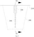
- FIG. 3 is a cross sectional view along lines in FIG. 2 ;
- FIG. 4 is an enlarged view of the A region in FIG. 3 ;
- FIG. 5 is a schematic structural diagram of the exothermic welding cup provided in the example of the present disclosure, viewed from a third viewing angle;
- FIG. 6 is a cross sectional view along lines VI-VI in FIG. 5 ;
- FIG. 7 is a schematic structural diagram of the exothermic welding cup not sealed by an encapsulation ring
- FIG. 8 is a schematic structural diagram of an igniter, connected to a cover, provided in the example of the present disclosure.
- FIG. 9 is a schematic structural diagram of the encapsulation ring provided in the example of the present disclosure.
- 010 exothermic welding cup
- 100 cup
- 200 cover
- 300 ignition
- 101 accommodating space
- 110 opening
- 111 flanging
- 310 heat
- 330 connector
- 350 connecting line
- 311 heating member
- 313 insulating member
- 315 spring leaf
- 3151 extension section
- 210 encapsulation ring
- 211 first pressing surface
- 213 second pressing surface
- 215 wire slot.
- mount can be either fixed connection, or detachable connection, or formed as a single piece; it can be either mechanical connection, or electrical connection; and it can be either direct connection, or indirect connection through an intermediate medium, and be inner communication between two elements or relationship of two elements.
- mount can be either fixed connection, or detachable connection, or formed as a single piece; it can be either mechanical connection, or electrical connection; and it can be either direct connection, or indirect connection through an intermediate medium, and be inner communication between two elements or relationship of two elements.
- a first feature being above or below a second feature can include direct connection between the first and the second features, and also include that the first and the second features are not in direct contact but in contact though other features between them.
- the first feature being above, over and on the second feature includes the first feature being immediately above or obliquely above the second feature, or merely indicates that a level of the first feature is higher than that of the second feature.
- the first feature being below, under and beneath the second feature includes the first feature being immediately below or obliquely below the second feature, or merely indicates a level of the first feature is lower than that of the second feature.
- exothermic welding cup 010 includes a cup 100 , a cover 200 and an igniter 300 .
- the cup 100 is in a shape of a circular truncated cone, and the cup 100 is made of copper, allowing that during exothermic welding, the cup 100 can be directly melted to form liquid copper, producing no residue required to be manually removed.
- An accommodating space 101 is formed inside the cup 100 , wherein welding powder and a heating member 311 for igniting the welding powder can be placed in the accommodating space 101 .
- the circular truncated cone shaped cup 100 has an opening 110 , the opening 110 being disposed on one surface, having a larger diameter, of the circular truncated cone, allowing the welding powder to be poured into the accommodating space 101 through the opening 110 easily.
- the opening 110 is further provided thereon with a flanging 111 , wherein the flanging 111 can not only facilitate removing some overfilled welding powder, but also provide a basis for sealing at the opening 110 .
- the cover 200 is connected to the igniter 300 , wherein the igniter 300 includes a heating portion 310 , a connecter 330 and a connecting line 350 .
- the heating portion 310 includes the heating member 311 , the heating member 311 being a spiral heating wire, which is formed by shaping a tungsten filament, wherein after powering up, the heating member 311 can generate considerable heat to reach a temperature capable of igniting the welding powder, and the high melting point of the tungsten filament also ensures that the heating member is less likely to be blown at a high temperature.
- the heating member 311 is electrically connected to the connector 330 via the connecting line 350 , wherein the connector 330 is used to connect a power supply, providing power to the heating member 311 by the power supply.
- the connector 330 includes a socket for connecting the power supply, namely the female connector commonly used in electronic devices.
- a conductive layer is disposed on an inner wall of the socket, the conductive layer being connected with the connecting line 350 , powering the heating member 311 by inserting the male connector of the power supply into the female connector.
- the resistance of the connecting line 350 should be minimized, hence the connecting line 350 uses a copper core.
- the contact between the heating member 311 and the cover 200 may cause a shorting, wherein the current directly passes through the cover 200 rather than through the heating member 311 , not only preventing the heating member 311 from generating heat, but also easily causing the current to be excessive to damage the power supply.
- an insulating member 313 is disposed between the heating member 311 and the cover 200 .
- two ends of the heating member 311 are connected to the connecting line 350 by using two spring leaves 315 to crimp, and the spring leaf 315 having a extension section 3151 , wherein the extension section 3151 bents toward the cover 200 .
- An insulating tip is disposed at an end of the extension section 3151 , wherein the insulating tip in this example is then the insulating member 313 , and the insulating tip is a PVC block.
- the PVC block is formed by the melted PVC material adhering to and solidified at the end of the extension section 3151 , and the PVC material itself is non-conductive, causing its arrangement at the end of the extension section 3151 can therefore insulate the extension section 3151 (indirectly insulate the heating member 311 ) and the cover 200 , preventing short circuit conditions.
- Other examples can also use the melted to adhere to the end of the extension section 3151 to form the insulating member 313 .
- an insulating rod can also be specifically provided, two insulating rods being disposed between the two ends of the spiral heating wire, wherein one end of the insulating rod remote from the heating portion 310 abut against the cover 200 , which can also prevent the heating member 311 from coming in contact with the cover 200 .
- An inside of the cup 100 is used to accommodate the welding powder, a particle size of the welding powder is generally small, to ensure the reaction rate and the thorough reaction, while the welding powder with small particle size tends to flow through the gap between the cup 100 and the cover 200 .
- glue can be used to carefully bond the cover 200 to the flanging 111 , ensuring the sealing performance, however the retention time of the glue is relatively short; and when in use, the high temperature generated in the cup 100 , may cause failure of the glue, so that the welding powder may escape, reducing welding efficiency and welding effect.
- an encapsulation ring 210 is used to attach the cover 200 and the cup 100 tightly, and the encapsulation ring 210 can seal the gap between the cover 200 and the cup 100 .
- the encapsulation ring 210 has a first pressing surface 211 and a second pressing surface 213 , a sealing groove being formed between the first pressing surface 211 and the second pressing surface 213 , wherein an edge of the cover 200 and the flanging 111 of the cup 100 are both accommodated in the sealing groove.
- the flanging 111 has a first surface close to the cup 100 and a second surface remote from the cup 100 , wherein the cover 200 covers the second surface, the first pressing surface 211 of the encapsulation ring 210 presses the cover 200 tightly, and the second pressing surface 213 presses the first surface of the flanging 111 tightly.
- the encapsulation ring 210 is formed by pressing a stainless steel sheet, a first through hole being disposed in the middle of the stainless steel sheet, and the first through hole exposing the middle portion of the cover 200 after the encapsulation ring 210 being mounted on the cup 100 .
- one side of the stainless steel sheet is further provided with an indentation, after pressing, the indentation forms a wire slot 215 of the encapsulation ring 210 , allowing the encapsulation ring 210 to seal the gap between the cover 200 and the cup 100 , and to ensure the connecting line 350 of the igniter 300 to pass through, that is to say that the wire slot 215 is used for the connecting line to pass therethrough.
- the exothermic welding cup 010 provided in the present disclosure can avoid contact between the heated heating member 311 and the cover 200 , which the latter may cause shorting; and the encapsulation ring 210 configured to seal the welding powder within the cup 100 can prevent the powder from falling out, and in practical welding process, the encapsulation ring 210 made of stainless steel is not prone to failure, ensuring effective encapsulation of the welding powder in the cup 100 within a certain welding time.
- exothermic welding capsule includes a cup 100 , a cover 200 , an igniter 300 and welding powder.
- the cup 100 is in a shape of a circular truncated cone, and the cup 100 is made of copper, allowing that during exothermic welding, the cup 100 can be directly melted to form liquid copper, producing no residue required to be manually removed.
- An accommodating space 101 is formed inside the cup 100 , wherein the welding powder and a heating member 311 for igniting the welding powder can be placed in the accommodating space 101 . After being placed in the accommodating space 101 , the welding powder needs to be shaken until uniform and fully filling the space, ensuring that the heating member 311 of a heating portion 310 is covered.
- the circular truncated cone shaped cup 100 has an opening 110 , the opening 110 being disposed on one surface, having a larger diameter, of the circular truncated cone, allowing the welding powder to be poured into the accommodating space 101 through the opening 110 easily.
- the opening 110 is further provided thereon with a flanging 111 , wherein the flanging 111 can not only facilitate removing some overfilled welding powder, but also provide a basis for sealing at the opening 110 .
- the cover 200 is connected to the igniter 300 , wherein the igniter 300 includes the heating portion 310 , a connecter 330 and a connecting line 350 .
- the heating portion 310 includes the heating member 311 , the heating member 311 being a spiral heating wire, which is formed by shaping a tungsten filament, wherein after powering up, the heating member 311 can generate considerable heat to reach a temperature capable of igniting the welding powder, and the high melting point of the tungsten filament also ensures that the heating member is less likely to be blown at a high temperature.
- the heating member 311 is electrically connected to the connector 330 via the connecting line 350 , wherein the connector 330 is used to connect a power supply, providing power to the heating member 311 by the power supply.
- the connector 330 includes a socket for connecting the power supply, namely the female connector commonly used in electronic devices.
- a conductive layer is disposed on an inner wall of the socket, the conductive layer being connected with the connecting line 350 , powering the heating member 311 by inserting the male connector of the power supply into the female connector.
- the resistance of the connecting line 350 should be minimized, hence the connecting line 350 uses a copper core.
- the contact between the heating member 311 and the cover 200 may cause a shorting, wherein the current directly passes through the cover 200 rather than through the heating member 311 , not only preventing the heating member 311 from generating heat, but also easily causing the current to be excessive to damage the power supply.
- an insulating member 313 is disposed between the heating member 311 and the cover 200 .
- two ends of the heating member 311 are connected to the connecting line 350 by using two spring leaves 315 to crimp, and the spring leaf 315 having an extension section 3151 , wherein the extension section 3151 bents toward the cover 200 .
- An insulating tip is disposed at an end of the extension section 3151 , wherein the insulating tip in this example is then the insulating member 313 , and the insulating tip is a PVC block.
- the PVC block is formed by the melted PVC material adhering to and solidified at the end of the extension section 3151 , and the PVC material itself is non-conductive, causing its arrangement at the end of the extension section 3151 can therefore insulate the extension section 3151 (indirectly insulate the heating member 311 ) and the cover 200 , preventing short circuit conditions.
- an insulating rod can also be specifically provided, two insulating rods being disposed between the two ends of the spiral heating wire, wherein one end of the insulating rod remote from the heating portion 310 abut against the cover 200 , which can also prevent the heating member 311 from coming in contact with the cover 200 .
- An inside of the cup 100 is used to accommodate the welding powder, a particle size of the welding powder is generally small, to ensure the reaction rate and the thorough reaction, while the welding powder with small particle size tends to flow through the gap between the cup 100 and the cover 200 .
- glue can be used to carefully bond the cover 200 to the flanging 111 , ensuring the sealing performance, however the retention time of the glue is relatively short; and when in use, the high temperature generated in the cup 100 , may cause failure of the glue, so that the welding powder may escape, reducing welding efficiency and welding effect.
- an encapsulation ring 210 is used to attach the cover 200 and the cup 100 tightly, and the encapsulation ring 210 can seal the gap between the cover 200 and the cup 100 .
- the encapsulation ring 210 has a first pressing surface 211 and a second pressing surface 213 , a sealing groove being formed between the first pressing surface 211 and the second pressing surface 213 , wherein an edge of the cover 200 and the flanging 111 of the cup 100 are both accommodated in the sealing groove.
- the flanging 111 has a first surface close to the cup 100 and a second surface remote from the cup 100 , wherein the cover 200 covers the second surface, the first pressing surface 211 of the encapsulation ring 210 presses the cover 200 tightly, and the second pressing surface 213 presses the first surface of the flanging 111 tightly.
- the encapsulation ring 210 is formed by pressing a stainless steel sheet, a first through hole being disposed in the middle of the stainless steel sheet, and the first through hole exposing the middle portion of the cover 200 after the encapsulation ring 210 being mounted on the cup 100 .
- one side of the stainless steel sheet is further provided with an indentation, after pressing, the indentation forms a wire slot 215 of the encapsulation ring 210 , allowing the encapsulation ring 210 to seal the gap between the cover 200 and the cup 100 , and to ensure the connecting line 350 of the igniter 300 to pass through, that is to say that the wire slot 215 is used for the connecting line to pass therethrough.
- the exothermic welding cup 010 provided in the present disclosure can avoid contact between the heated heating member 311 and the cover 200 , which the latter may cause shorting; and the encapsulation ring 210 configured to seal the welding powder within the cup 100 can prevent the powder from falling out, and in practical welding process, the encapsulation ring 210 made of stainless steel is not prone to failure, ensuring effective encapsulation of the welding powder in the cup 100 within a certain welding time.
Landscapes
- Engineering & Computer Science (AREA)
- Mechanical Engineering (AREA)
- Physics & Mathematics (AREA)
- Optics & Photonics (AREA)
- Chemical & Material Sciences (AREA)
- Chemical Kinetics & Catalysis (AREA)
- Air Bags (AREA)
Abstract
Description
Claims (16)
Applications Claiming Priority (4)
| Application Number | Priority Date | Filing Date | Title |
|---|---|---|---|
| CN201820065601U | 2018-01-15 | ||
| CN201820065601.4U CN207788042U (en) | 2018-01-15 | 2018-01-15 | A kind of exothermic weld cup and exothermic weld capsule |
| CN201820065601.4 | 2018-01-15 | ||
| PCT/CN2018/119695 WO2019137124A1 (en) | 2018-01-15 | 2018-12-07 | Exothermic welding cup and exothermic welding capsule |
Publications (2)
| Publication Number | Publication Date |
|---|---|
| US20190389014A1 US20190389014A1 (en) | 2019-12-26 |
| US10821561B2 true US10821561B2 (en) | 2020-11-03 |
Family
ID=63272092
Family Applications (1)
| Application Number | Title | Priority Date | Filing Date |
|---|---|---|---|
| US16/481,967 Active US10821561B2 (en) | 2018-01-15 | 2018-12-07 | Exothermic welding cup and exothermic welding capsule |
Country Status (3)
| Country | Link |
|---|---|
| US (1) | US10821561B2 (en) |
| CN (1) | CN207788042U (en) |
| WO (1) | WO2019137124A1 (en) |
Cited By (1)
| Publication number | Priority date | Publication date | Assignee | Title |
|---|---|---|---|---|
| US20240278350A1 (en) * | 2021-06-15 | 2024-08-22 | Erico International Corporation | Exothermic Welding System |
Families Citing this family (3)
| Publication number | Priority date | Publication date | Assignee | Title |
|---|---|---|---|---|
| WO2019095098A1 (en) * | 2017-11-14 | 2019-05-23 | 四川桑莱特智能电气设备股份有限公司 | Exothermic welding device and exothermic welding method |
| CN207788042U (en) | 2018-01-15 | 2018-08-31 | 四川桑莱特智能电气设备股份有限公司 | A kind of exothermic weld cup and exothermic weld capsule |
| CA3253015A1 (en) * | 2022-02-25 | 2023-08-31 | Hubbell Incorporated | Exothermic reaction weld metal assemblies and methods of use |
Citations (15)
| Publication number | Priority date | Publication date | Assignee | Title |
|---|---|---|---|---|
| US4879452A (en) * | 1988-04-04 | 1989-11-07 | Erico International Corporation | Exothermic welding apparatus and method |
| US4885452A (en) * | 1988-04-04 | 1989-12-05 | Erico International Corporation | Exothermic welding and method |
| US5425496A (en) * | 1993-03-09 | 1995-06-20 | University Of Cincinnati | Method for joining ceramic and metal-ceramic heating elements to electrical terminals by micropyretic synthesis, compositions for electrical terminals and heaters comprising the same |
| CA2474453A1 (en) * | 2002-01-25 | 2003-08-07 | Erico International Corporation | Welding apparatus and method |
| US20040222274A1 (en) * | 2003-05-07 | 2004-11-11 | Harger Timothy R. | Exothermic welding |
| CN201144064Y (en) | 2008-01-18 | 2008-11-05 | 何迎春 | Packaging structure for solder |
| US7946466B1 (en) * | 2009-12-07 | 2011-05-24 | Continental Industries, Inc. | Alternative ignition source system for an exothermic reaction mold device |
| US7950568B2 (en) * | 2008-01-04 | 2011-05-31 | Harger, Inc. | Exothermic welding assembly |
| US20110132967A1 (en) * | 2009-12-07 | 2011-06-09 | Continental Industries, Inc. | Ignition Source System for an Exothermic Reaction Mold Device |
| US20110240244A1 (en) * | 2010-04-05 | 2011-10-06 | Sepelak Timothy P | Exothermic welding mold with integral cover |
| ES2384850A1 (en) * | 2012-03-20 | 2012-07-13 | Aplicaciones Tecnológicas, S.A. | Ignition device for exothermic welding, exothermic welding mould for the ignition device, and exothermic welding apparatus comprising the mould and the device |
| US20150328716A1 (en) * | 2011-10-20 | 2015-11-19 | Klk Electro Materiales, S.A. | Device and process for remote ignition in aluminothermic welding |
| CN107030372A (en) | 2017-05-31 | 2017-08-11 | 无锡市格林电工装备有限公司 | Safety-type remote control is ignited rod |
| CN207788042U (en) | 2018-01-15 | 2018-08-31 | 四川桑莱特智能电气设备股份有限公司 | A kind of exothermic weld cup and exothermic weld capsule |
| US20190143446A1 (en) * | 2017-11-14 | 2019-05-16 | Sichuan Sunlight Intelligent Electric Equipment Co., Ltd. | Exothermic welding apparatus and exothermic welding method |
Family Cites Families (5)
| Publication number | Priority date | Publication date | Assignee | Title |
|---|---|---|---|---|
| US5145106A (en) * | 1989-08-03 | 1992-09-08 | Erico International Corporation | Welding apparatus and method |
| CN201105359Y (en) * | 2007-07-25 | 2008-08-27 | 余旭东 | Remote-control electrical heating exothermal fusion welding initiation device |
| CN202622174U (en) * | 2012-04-09 | 2012-12-26 | 驭雷(上海)机电科技有限公司 | Exothermic low-tension ignition metal-welding device |
| CN105752429B (en) * | 2016-04-22 | 2018-09-04 | 宁波高新区远创科技有限公司 | Packaging structure for welding powder |
| CN206427486U (en) * | 2016-09-29 | 2017-08-22 | 何迎春 | A kind of packaging structure for welding powder |
-
2018
- 2018-01-15 CN CN201820065601.4U patent/CN207788042U/en active Active
- 2018-12-07 US US16/481,967 patent/US10821561B2/en active Active
- 2018-12-07 WO PCT/CN2018/119695 patent/WO2019137124A1/en not_active Ceased
Patent Citations (15)
| Publication number | Priority date | Publication date | Assignee | Title |
|---|---|---|---|---|
| US4885452A (en) * | 1988-04-04 | 1989-12-05 | Erico International Corporation | Exothermic welding and method |
| US4879452A (en) * | 1988-04-04 | 1989-11-07 | Erico International Corporation | Exothermic welding apparatus and method |
| US5425496A (en) * | 1993-03-09 | 1995-06-20 | University Of Cincinnati | Method for joining ceramic and metal-ceramic heating elements to electrical terminals by micropyretic synthesis, compositions for electrical terminals and heaters comprising the same |
| CA2474453A1 (en) * | 2002-01-25 | 2003-08-07 | Erico International Corporation | Welding apparatus and method |
| US20040222274A1 (en) * | 2003-05-07 | 2004-11-11 | Harger Timothy R. | Exothermic welding |
| US7950568B2 (en) * | 2008-01-04 | 2011-05-31 | Harger, Inc. | Exothermic welding assembly |
| CN201144064Y (en) | 2008-01-18 | 2008-11-05 | 何迎春 | Packaging structure for solder |
| US7946466B1 (en) * | 2009-12-07 | 2011-05-24 | Continental Industries, Inc. | Alternative ignition source system for an exothermic reaction mold device |
| US20110132967A1 (en) * | 2009-12-07 | 2011-06-09 | Continental Industries, Inc. | Ignition Source System for an Exothermic Reaction Mold Device |
| US20110240244A1 (en) * | 2010-04-05 | 2011-10-06 | Sepelak Timothy P | Exothermic welding mold with integral cover |
| US20150328716A1 (en) * | 2011-10-20 | 2015-11-19 | Klk Electro Materiales, S.A. | Device and process for remote ignition in aluminothermic welding |
| ES2384850A1 (en) * | 2012-03-20 | 2012-07-13 | Aplicaciones Tecnológicas, S.A. | Ignition device for exothermic welding, exothermic welding mould for the ignition device, and exothermic welding apparatus comprising the mould and the device |
| CN107030372A (en) | 2017-05-31 | 2017-08-11 | 无锡市格林电工装备有限公司 | Safety-type remote control is ignited rod |
| US20190143446A1 (en) * | 2017-11-14 | 2019-05-16 | Sichuan Sunlight Intelligent Electric Equipment Co., Ltd. | Exothermic welding apparatus and exothermic welding method |
| CN207788042U (en) | 2018-01-15 | 2018-08-31 | 四川桑莱特智能电气设备股份有限公司 | A kind of exothermic weld cup and exothermic weld capsule |
Non-Patent Citations (4)
| Title |
|---|
| International Search Report dated Feb. 27, 2019, issued in corresponding International Application No. PCT/CN2018/119695. |
| Machine translation of CN107030372A (no date available). * |
| Machine translation of CN201144064A (no date available). * |
| Machine translation of CN207788042A (no date available). * |
Cited By (1)
| Publication number | Priority date | Publication date | Assignee | Title |
|---|---|---|---|---|
| US20240278350A1 (en) * | 2021-06-15 | 2024-08-22 | Erico International Corporation | Exothermic Welding System |
Also Published As
| Publication number | Publication date |
|---|---|
| CN207788042U (en) | 2018-08-31 |
| US20190389014A1 (en) | 2019-12-26 |
| WO2019137124A1 (en) | 2019-07-18 |
Similar Documents
| Publication | Publication Date | Title |
|---|---|---|
| US10821561B2 (en) | Exothermic welding cup and exothermic welding capsule | |
| CN109643773A (en) | Integrated electrical feedthrough component for battery case wall | |
| CN100492574C (en) | Temperature fuse, and battery using same | |
| US10758997B2 (en) | Exothermic welding apparatus and exothermic welding method | |
| CN211605079U (en) | Paster current fuse of electrode fuse integrated structure | |
| CN102136402A (en) | Temperature-sensitive element and packaged battery | |
| CN202268525U (en) | Sealed connector | |
| JP2005158352A (en) | Electric wire with fuse | |
| CN104769793A (en) | Surge absorber and method for manufacturing same | |
| WO2023010780A1 (en) | Button cell assembly and electronic device | |
| CN207486848U (en) | A kind of igniter and welder | |
| CN216928467U (en) | Over-temperature protection fusing resistor for switching power supply | |
| CN214588708U (en) | Miniature fuse | |
| CN216161674U (en) | Hybrid electrode temperature fuse | |
| JP2016162683A (en) | High voltage electric circuit protection fuse | |
| EP1056111B1 (en) | Method for producing lamps | |
| CN203300585U (en) | Surface Mount Fuses with Solderless Terminations | |
| CN113314870A (en) | Special-shaped terminal adaptive to different interfaces | |
| CN100557763C (en) | Solderless connection of dielectric impedance discharge lamps | |
| CN217991210U (en) | Welding head assembly and welding equipment | |
| CN208028578U (en) | A kind of Surge Protector | |
| CN218182061U (en) | Self-breaking type explosion-proof capacitor | |
| CN213124360U (en) | Filtering fuse | |
| CN219874056U (en) | A tool-less wire nose connector | |
| CN219739485U (en) | Quick-plug safety structure of socket |
Legal Events
| Date | Code | Title | Description |
|---|---|---|---|
| AS | Assignment |
Owner name: SUNLIGHT CHENGDU XIHANGGANG ELECTRIC MANUFACTURING Free format text: ASSIGNMENT OF ASSIGNORS INTEREST;ASSIGNORS:YU, XUDONG;CHEN, FANJIAO;LYU, ZHOUBO;REEL/FRAME:049909/0986 Effective date: 20190718 Owner name: SUNLIGHT CHENGDU XIHANGGANG ELECTRIC MANUFACTURING CO., LTD., CHINA Free format text: ASSIGNMENT OF ASSIGNORS INTEREST;ASSIGNORS:YU, XUDONG;CHEN, FANJIAO;LYU, ZHOUBO;REEL/FRAME:049909/0986 Effective date: 20190718 |
|
| FEPP | Fee payment procedure |
Free format text: ENTITY STATUS SET TO UNDISCOUNTED (ORIGINAL EVENT CODE: BIG.); ENTITY STATUS OF PATENT OWNER: SMALL ENTITY |
|
| FEPP | Fee payment procedure |
Free format text: ENTITY STATUS SET TO SMALL (ORIGINAL EVENT CODE: SMAL); ENTITY STATUS OF PATENT OWNER: SMALL ENTITY |
|
| STPP | Information on status: patent application and granting procedure in general |
Free format text: NON FINAL ACTION MAILED |
|
| STPP | Information on status: patent application and granting procedure in general |
Free format text: RESPONSE TO NON-FINAL OFFICE ACTION ENTERED AND FORWARDED TO EXAMINER |
|
| STPP | Information on status: patent application and granting procedure in general |
Free format text: PUBLICATIONS -- ISSUE FEE PAYMENT VERIFIED |
|
| STCF | Information on status: patent grant |
Free format text: PATENTED CASE |
|
| MAFP | Maintenance fee payment |
Free format text: PAYMENT OF MAINTENANCE FEE, 4TH YR, SMALL ENTITY (ORIGINAL EVENT CODE: M2551); ENTITY STATUS OF PATENT OWNER: SMALL ENTITY Year of fee payment: 4 |