US10821372B2 - Building blocks for a toy building set - Google Patents
Building blocks for a toy building set Download PDFInfo
- Publication number
- US10821372B2 US10821372B2 US16/058,509 US201816058509A US10821372B2 US 10821372 B2 US10821372 B2 US 10821372B2 US 201816058509 A US201816058509 A US 201816058509A US 10821372 B2 US10821372 B2 US 10821372B2
- Authority
- US
- United States
- Prior art keywords
- wall
- building block
- wall section
- side edge
- walls
- Prior art date
- Legal status (The legal status is an assumption and is not a legal conclusion. Google has not performed a legal analysis and makes no representation as to the accuracy of the status listed.)
- Expired - Fee Related
Links
Images


Classifications
-
- A—HUMAN NECESSITIES
- A63—SPORTS; GAMES; AMUSEMENTS
- A63H—TOYS, e.g. TOPS, DOLLS, HOOPS OR BUILDING BLOCKS
- A63H33/00—Other toys
- A63H33/04—Building blocks, strips, or similar building parts
- A63H33/06—Building blocks, strips, or similar building parts to be assembled without the use of additional elements
- A63H33/08—Building blocks, strips, or similar building parts to be assembled without the use of additional elements provided with complementary holes, grooves, or protuberances, e.g. dovetails
- A63H33/086—Building blocks, strips, or similar building parts to be assembled without the use of additional elements provided with complementary holes, grooves, or protuberances, e.g. dovetails with primary projections fitting by friction in complementary spaces between secondary projections, e.g. sidewalls
-
- A—HUMAN NECESSITIES
- A63—SPORTS; GAMES; AMUSEMENTS
- A63H—TOYS, e.g. TOPS, DOLLS, HOOPS OR BUILDING BLOCKS
- A63H33/00—Other toys
- A63H33/04—Building blocks, strips, or similar building parts
- A63H33/044—Buildings
Definitions
- the present disclosure relates to building blocks for a toy building set.
- Such building blocks are known to be made of a rigid plastic and further provided with a number of cylindrical projections that fit with sufficient tightness into the hollow of another building block or into the hollows of two or more adjacent building blocks, thus permitting the construction of toy buildings/structures in three dimensions.
- a building block for a toy building set the building block being releasably joinable to another building block, the building block comprising:
- a hollow main body defining:
- each one of the spaced apart recess sections being in a substantial alignment with a corresponding one of the spaced apart projections;
- a longitudinal groove is provided between the second wall section and the hollow main body of the other building block when the building block is fully connected to the other building block.
- the building block as defined above, wherein the first wall section defines a first surface area and the second wall section defines a second surface area, the second surface area being greater than the first surface area.
- the building block as defined above, wherein the first wall section defines a first wall section upper longitudinal edge and the second wall section defines a second wall section upper longitudinal edge, and further wherein the longitudinal groove is formed between the second wall section upper longitudinal edge, at least part of the first wall surface and the lower surface of the hollow main body of the other building block when the building block is fully connected to the other building block.
- the building block as defined above, wherein the upper surface defines an upper surface first longitudinal edge and an upper surface second longitudinal edge distant from the upper surface first longitudinal edge.
- the building block as defined above, wherein the first wall section upper longitudinal edge corresponds to one of the upper surface first and second longitudinal edges.
- the building block as defined above, wherein the second wall section upper longitudinal edge is parallel to and distant from the upper surface first and second longitudinal edges.
- the building block as defined above, wherein the lower surface defines a lower surface first longitudinal edge and a lower surface second longitudinal edge distant from the lower surface first longitudinal edge; and further wherein the first wall section defines a first wall section lower edge and the second wall section defines a second wall section lower longitudinal edge, both the first wall section lower edge and the second wall section lower longitudinal edges corresponding to one of the lower surface first and second longitudinal edges.
- the building block as defined above, wherein the first wall section further defines: a first wall section first side edge; and a first wall section second side edge opposite the first wall section first side edge; and further wherein the second wall section further defines: a second wall section first side edge; and a second wall section second side edge opposite the second wall section first side edge.
- the building block as defined above, wherein the first wall section first side edge is at a distance from the second wall section first side edge.
- the building block as defined above, wherein the first wall section second side edge is at a distance from the second wall section second side edge.
- the building block as defined above, wherein the hollow main body further defines spaced apart receiving grooves inbetween at least some of the spaced apart projections and about the upper surface.
- each one of the spaced apart projections comprises: a projection upper surface; and projection walls joining the projection upper surface and the upper surface of the hollow main body.
- the building block as defined above, wherein the hollow main body defines wall inner surfaces, the building block further comprising: an inner wall within the hollow main body, extending from the lower surface towards the upper surface and joining together two of the walls, the inner wall together with some of the walls forming the spaced apart recess sections.
- the building block as defined above, wherein the hollow main body defines wall inner surfaces, the building block further comprising: spaced apart inner walls within the hollow main body, each one of the spaced apart inner walls extending from the lower surface towards the upper surface and joining together two of the walls, the spaced apart inner walls together with some of the walls forming the spaced apart recess sections.
- the building block as defined above further comprising: inner longitudinal protrusions extending from the lower surface towards the upper surface outwardly from each one of the wall inner surfaces and further outwardly from each one of the spaced apart inner walls, wherein each one of the inner longitudinal protrusions is adapted to interface with a corresponding one of the projection walls when the building block is fully connected to the other building block.
- the building block as defined above, wherein the hollow main body defines a cross-sectional surface area, the cross-section surface area defining at least one of: a rectangular shape, a squared shape, an incurved shape, an L-like shape, a T-like shape, an incurved L-like shape, an incurved T-like shape, a ring shape and a rounded shape.
- each one of the spaced apart projections comprises: a projection upper surface defining a substantially squared surface; and four projection walls joining the projection upper surface and the upper surface of the hollow main body.
- the building block as defined above, wherein one of the four projection walls extend from the upper surface respectively at the upper surface first and second longitudinal edges.
- the building block as defined above wherein two of the four projection walls extend from the upper surface respectively at the upper surface first and second longitudinal edges.
- each one of the spaced apart receiving grooves and the longitudinal groove is configured to releasably connect with at least one of: a toy flooring component, a toy window component, a toy bridge component and a toy roofing component.
- FIG. 1 is a top perspective view of a toy building, or structure, in accordance with an embodiment
- FIG. 2A is top perspective view of some building blocks being connected one to another in accordance with another embodiment
- FIG. 2B is another top perspective view of the building blocks shown in FIG. 2A ;
- FIG. 2C is a front elevation view of some of the building blocks shown in FIG. 2A ;
- FIG. 3A is a top perspective view of a two-head building block in accordance with a further embodiment
- FIG. 3B is another top perspective view of the two-head building block shown in FIG. 3A ;
- FIG. 3C is a front elevation view of the two-head building block shown in FIG. 3A ;
- FIG. 3D is a side elevation view of the two-head building block shown in FIG. 3A ;
- FIG. 3E is a top plan view of the two-head building block shown in FIG. 3A ;
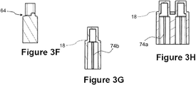
- FIG. 3F is a cross-sectional view of the two-head building block shown in FIG. 3E , taken along line A-A;
- FIG. 3G is a cross-sectional view of the two-head building block shown in FIG. 3E , taken along line B-B;
- FIG. 3H is a cross-sectional view of the two-head building block shown in FIG. 3E , taken along line C-C;
- FIG. 3I is a bottom plan view of the two-head building block shown in FIG. 3A ;
- FIG. 4A is a top perspective view of a four-head building block in accordance with yet another embodiment
- FIG. 4B is another top perspective view of the four-head building block shown in FIG. 4A ;
- FIG. 4C is a front elevation view of the four-head building block shown in FIG. 4A ;
- FIG. 4D is a side elevation view of the four-head building block shown in FIG. 4A ;
- FIG. 4E is a top plan view of the four-head building block shown in FIG. 4A ;
- FIG. 4F is a cross-sectional view of the four-head building block shown in FIG. 4E , taken along line D-D;
- FIG. 4G is a cross-sectional view of the four-head building block shown in FIG. 4E , taken along line E-E;
- FIG. 4H is a cross-sectional view of the four-head building block shown in FIG. 4E , taken along line F-F;
- FIG. 4I is a bottom plan view of the four-head building block shown in FIG. 4A ;
- FIG. 5A is a top perspective view of three four-head building blocks, as shown in FIGS. 4A-4I , connected together;
- FIG. 5B is cross-sectional front elevation view of the three connected four-head building blocks shown in FIG. 5A ;
- FIG. 5C is a side elevation side elevation view of the three connected four-head building blocks shown in FIG. 5A ;
- FIG. 5D is a closed-up view of the connected building blocks shown in FIG. 5B ;
- FIG. 6A is a top perspective view of a five-head building block (right corner building block) in accordance with another embodiment
- FIG. 6B is another top perspective view of the five-head building block shown in FIG. 6A ;
- FIG. 6C is a front elevation view of the five-head building block shown in FIGS. 6A-6B ;
- FIG. 6D is a side elevation view of the five-head building block shown in FIGS. 6A-6B ;
- FIG. 6E is a top plan view of the five-head building block shown in FIGS. 6A-6B ;
- FIG. 6F is a cross-sectional view of the five-head building block shown in FIG. 6E , taken along line G-G;
- FIG. 6G is a cross-sectional view of the five-head building block shown in FIG. 6E , taken along line H-H;
- FIG. 6H is a cross-sectional view of the five-head building block shown in FIG. 6E , taken along line I-I;
- FIG. 6I is a cross-sectional view of the five-head building block shown in FIG. 6E , taken along line J-J;
- FIG. 6J is a bottom plan view of the five-head building block shown in FIGS. 6A-6B ;
- FIG. 7A is a top perspective view of another five-head building block (left corner building block) in accordance with a further embodiment
- FIG. 7B is another top perspective view of the five-head building block shown in FIG. 7A ;
- FIG. 7C is a front elevation view of the five-head building block shown in FIGS. 7A-7B ;
- FIG. 7D is a side elevation view of the five-head building block shown in FIGS. 7A-7B ;
- FIG. 7E is a top plan view of the five-head building block shown in FIGS. 7A-7B ;
- FIG. 7F is a cross-sectional view of the five-head building block shown in FIG. 7E , taken along line K-K;
- FIG. 7G is a cross-sectional view of the five-head building block shown in FIG. 7E , taken along line L-L;
- FIG. 7H is a cross-sectional view of the five-head building block shown in FIG. 7E , taken along line M-M;
- FIG. 7I is a bottom plan view of the five-head building block shown in FIGS. 7A-7B ;
- FIG. 8A is a top perspective view of a curved four-head building block in accordance with yet another embodiment
- FIG. 8B is another top perspective view of the curved four-head building block shown in FIG. 8A ;
- FIG. 8C is a front elevation view of the curved four-head building block shown in FIGS. 8A-8B ;
- FIG. 8D is a side elevation view of the curved four-head building block shown in FIGS. 8A-8B ;
- FIG. 8E is a top plan view of the curved four-head building block shown in FIGS. 8A-8B ;
- FIG. 8F is a cross-sectional view of the curved four-head building block shown in FIG. 8E , taken along line N-N;
- FIG. 8G is a cross-sectional view of the curved four-head building block shown in FIG. 8E , taken along line O-O;
- FIG. 8H is a cross-sectional view of the curved four-head building block shown in FIG. 8E , taken along line P-P;
- FIG. 8I is a bottom plan view of the curved four-head building block shown in FIGS. 8A-8B ;
- FIG. 9A is a top perspective view of another curved four-head building block (tower right corner building block) in accordance with another embodiment, where only two of the four heads are providing a curve to the building block;
- FIG. 9B is another top perspective view of the curved four-head building block shown in FIG. 9A ;
- FIG. 9C is a front elevation view of the curved four-head building block shown in FIGS. 9A-9B ;
- FIG. 9D is a side elevation view of the curved four-head building block shown in FIGS. 9A-9B ;
- FIG. 9E is a top plan view of the curved four-head building block shown in FIGS. 9A-9B ;
- FIG. 9F is a cross-sectional view of the curved four-head building block shown in FIG. 9E , taken along line Q-Q;
- FIG. 9G is a cross-sectional view of the curved four-head building block shown in FIG. 9E , taken along line R-R;
- FIG. 9H is a cross-sectional view of the curved four-head building block shown in FIG. 9E , taken along line S-S;
- FIG. 9I is a bottom plan view of the curved four-head building block shown in FIGS. 9A-9B ;
- FIG. 10A is a top perspective view of a further curved four-head building block (tower left corner building block) in accordance with a further embodiment, where only two of the four heads are providing a curve to the building block;
- FIG. 10B is another top perspective view of the curved four-head building block shown in FIG. 10A ;
- FIG. 10C is a front elevation view of the curved four-head building block shown in FIGS. 10A-10B ;
- FIG. 10D is a side elevation view of the curved four-head building block shown in FIGS. 10A-10B ;
- FIG. 10E is a top plan view of the curved four-head building block shown in FIGS. 10A-10B ;
- FIG. 10F is a cross-sectional view of the curved four-head building block shown in FIG. 10E , taken along line T-T;
- FIG. 10G is a cross-sectional view of the curved four-head building block shown in FIG. 10E , taken along line U-U;
- FIG. 10H is a cross-sectional view of the curved four-head building block shown in FIG. 10E , taken along line V-V;
- FIG. 10I is a bottom plan view of the curved four-head building block shown in FIGS. 10A-10B ;
- FIG. 11 is a top plan view of a curved three-head building block in accordance with yet another embodiment
- FIG. 12 is a top plan view of a curved two-head building block in accordance with another embodiment
- FIG. 13 is a top plan view of a curved one-head building block in accordance with a further embodiment
- FIG. 14 is a top plan view of a corner three-head building block in accordance with yet another embodiment
- FIG. 15A is a front elevation view of a window building block in accordance with another embodiment
- FIG. 15B is a side elevation view of the window building block of FIG. 15A ;
- FIG. 15C is a top plan view of the window building block of FIG. 15A ;
- FIG. 15D is a bottom plan view of the window building block of FIG. 15A ;
- FIG. 16A is a front elevation view of a curved window building block in accordance with a further embodiment
- FIG. 16B is a side elevation view of the curved window building block of FIG. 16A ;
- FIG. 16C is a top plan view of the curved window building block of FIG. 16A ;
- FIG. 16D is a bottom plan view of the curved window building block of FIG. 16A ;
- FIG. 17 is a front elevation view of a roof building block in accordance with yet another embodiment.
- FIG. 18 is a front elevation view of a roof building block in accordance with another embodiment
- FIG. 19 is a front elevation view of a roof building block in accordance with a further embodiment.
- FIG. 20 is a front elevation view of a post building block in accordance with yet another embodiment.
- FIG. 21 is a perspective view of a toy building, or structure, in accordance with another embodiment, showing a flooring building block interfacing with the longitudinal groove defined by some of the building blocks.
- Toy building 12 is made of a plurality of connected together building blocks and building block components, such as, window building blocks 80 , roof building blocks 82 , post building blocks 84 , door building blocks 86 and the like.
- FIGS. 2A to 2C there are shown a plurality of building blocks, namely building blocks 10 , 110 , 210 , 310 , 410 , 510 , 610 , that are releasably connected one to another such as to provide part of a toy building 12 , or toy structure.
- configuration of each one of the building blocks 10 , 110 , 210 , 310 , 410 , 510 , 610 provides a useful alternative to known building blocks as horizontally oriented longitudinal grooves 34 and vertically oriented longitudinal grooves 35 are provided inbeetween the plurality of fully connected building blocks, here building blocks 110 .
- Such horizontally and vertically oriented longitudinal grooves 34 , 35 therefore provide the toy building 12 with a special appearance, as bricks look to be connected one adjacent another.
- Building block 10 comprises a substantially rectangular hollow main body 14 defining a lower surface 16 , which is adapted to support hollow main body 14 , and an upper surface 18 , opposite lower surface 16 .
- Building block 10 further comprises four walls 20 a , 20 b , 20 c , 20 d that together join lower surface 16 and upper surface 18 . As best shown in FIGS.
- some of the walls 20 a , 20 b , 20 c , 20 d each comprises a first wall section 22 a , 22 c which defines a first wall surface 24 a , 24 c , as well as a second wall section 26 a , 26 c , which defines a second wall surface 28 a , 28 c .
- Second wall surfaces 28 a , 28 c are parallel to and distant from first wall surfaces 24 a , 24 c (second wall surface 28 a is parallel to and distant from first wall surface 24 a , while second wall surface 28 c is parallel to and distant from first wall surface 24 c ).
- building block 10 further comprises spaced apart projections or heads 30 a , 30 b , that extend from upper surface 18 in a direction opposite lower surface 16 .
- Building block 10 further comprises spaced apart recess sections 32 a , 32 b ( FIG. 3I ) disposed within hollow main body 14 about lower surface 16 .
- Each one of the spaced apart recess sections 32 a , 32 b is being in a substantial alignment with a corresponding one of the spaced apart projections 30 a , 30 b.
- an horizontally oriented longitudinal groove 34 is provided/created between second wall section 26 a , 26 c of lower building block 10 and hollow main body 14 of upper building block 10 when lower building block 10 is fully connected to upper building block 10 ( FIGS. 1A, 1B, 1D, 4A and 4B ).
- first wall sections 22 a , 22 c each defines a first surface area and second wall sections 26 a , 26 c each defines a second surface area, and that the second surface areas are being greater than the first surface areas.
- Each one of the first wall sections 22 a , 22 c further defines a first wall section upper longitudinal edge 42 a , 42 c and each one of the second wall sections 26 a , 26 c defines a second wall section upper longitudinal edge 40 a , 40 c .
- horizontally oriented longitudinal groove 34 is formed between second first wall section upper longitudinal edges 42 a , 42 c (of lower building block 10 ), at least part of first wall surfaces 24 a , 24 c (of lower building block 10 ) and lower surface 16 of hollow main body 14 of upper building block 10 , again, when building blocks 10 are fully connected one to another.
- upper surface 18 defines an upper surface first longitudinal edge 44 and an upper surface second longitudinal edge 46 , which is distant from upper surface first longitudinal edge 44 .
- second wall section upper longitudinal edges 40 a , 40 c respectively correspond to upper surface first and second longitudinal edges 44 , 46 .
- first wall section upper longitudinal edges 42 a , 42 c are parallel to and distant from upper surface first and second longitudinal edges 44 , 46 respectively.
- lower surface 16 defines a lower surface first longitudinal edge 48 and a lower surface second longitudinal edge 50 , which is distant from lower surface first longitudinal edge 48 .
- each one of the first wall sections 22 a , 22 c defines a first wall section lower edge 52 a , 52 c and each one of second wall sections 26 a , 26 c defines a second wall section lower longitudinal edge 54 a , 54 c .
- Both first wall section lower edges 52 a , 52 c and second wall section lower longitudinal edges 54 a , 54 c correspond to respectively lower surface first and second longitudinal edges 48 , 50 .
- first wall sections 22 a , 22 c further defines a first wall section side edge 56 a , 56 b , 56 c , 56 d .
- each one of the second wall sections 26 a , 26 c further defines a second wall section side edge 60 a , 60 b , 60 c , 60 d . Therefore, according to the two-head building block 10 shown in FIGS. 3A to 3I , first wall section side edge 56 a is at a distance from second wall section side edge 60 a and similarly, first wall section side edge 56 b is at a distance from second wall section side edge 60 b .
- first wall section side edge 56 c is at a distance from second wall section side edge 60 c and similarly, first wall section side edge 56 d is at a distance from second wall section side edge 60 d of wall 20 c ( FIG. 3E ). Therefore, vertically oriented longitudinal groove 35 is formed between second wall section side edges of two adjacent building blocks, as shown in FIG. 2C , and at least part of first wall surfaces 24 a , 24 c (of such adjacent blocks), again, when building blocks 10 are fully connected one adjacent another.
- hollow main body 14 further defines a receiving groove 64 inbetween spaced apart projections 30 a , 30 b and about upper surface 18 .
- Such receiving groove 64 is configured to releasably connect with, or receive, a plurality of additional building components, such as, without limitations, toy flooring components, toy window components, toy bridge components, toy roofing components and the like.
- each one of the spaced apart projections 30 a , 30 b comprises a projection upper surface 66 , defining a substantially squared surface, and projection walls 68 a , 68 b , 68 c , 68 d , joining projection upper surface 66 and upper surface 18 of hollow main body 14 .
- the substantially squared surface may prevent a building block to rotate when releasably connected to another building block, even if connected by only one projection 30 a or 30 b .
- projection wall 68 a For each one of the spaced apart projections, or heads, 30 a , 30 b , two of the four projection walls, namely projection walls 68 a , 68 c , extend from upper surface 18 respectively at the upper surface first and second longitudinal edges 44 , 48 . Therefore, as shown, projection wall 68 a share the same plan with first wall surface 24 a of wall 20 a , while projection wall 68 c share the same plan with first wall surface 24 c of wall 20 c.
- hollow main body 14 defines wall inner surfaces 70 a , 70 b , 70 c , 70 d .
- Building block 10 also further comprises an inner wall 72 , within hollow main body 14 .
- Inner wall 72 extends from lower surface 16 towards upper surface 18 and joins together walls 20 a , 20 c .
- Inner wall 72 together with walls 20 a , 20 b , 20 c , 20 d , forms the spaced apart recess sections 32 a , 32 b.
- Building block 10 further comprises inner longitudinal protrusions (four inner longitudinal protrusions 74 a , 74 b , 74 c , 74 d for each one of the recess sections 32 a , 32 b ).
- Each one of the inner longitudinal protrusions 74 a , 74 b , 74 c , 74 d longitudinally extends from lower surface 16 towards upper surface 18 .
- Only some of the inner longitudinal protrusions, namely protrusions 74 a , 74 c extend outwardly from wall inner surfaces 70 a , 70 c , while the remaining ones extend outwardly from inner wall 72 .
- Each one of the inner longitudinal protrusions 74 a , 74 b , 74 c , 74 d is adapted to interface with a corresponding one of projection walls 68 a , 68 b , 68 c , 68 d when a lower building block 10 (or any other building 10 , 110 , 210 , 310 , 410 , 510 , 610 and the like) is fully connected to an upper building block 10 (or any other building 110 , 210 , 310 , 410 , 510 , 610 and the like).
- building block 110 comprises a substantially rectangular hollow main body 114 defining a lower surface 116 , which is adapted to support hollow main body 114 , and an upper surface 118 , opposite lower surface 116 .
- Building block 110 further comprises four walls 120 a , 120 b , 120 c , 120 d that together join lower surface 116 and upper surface 118 . As best shown in FIGS.
- some of the walls 120 a , 120 b , 120 c , 120 d each comprises a first wall section 122 a , 122 c which defines a first wall surface 124 a , 124 c , as well as a second wall section 126 a , 126 c , which defines a second wall surface 128 a , 128 c .
- Second wall surfaces 128 a , 128 c are parallel to and distant from first wall surfaces 124 a , 124 c (second wall surface 128 a is parallel to and distant from first wall surfaces 124 a , while second wall surface 128 c is parallel to and distant from first wall surfaces 124 c ).
- building block 110 further comprises spaced apart projections or heads 130 a , 130 b , 130 c , 130 d that extend from upper surface 118 in a direction opposite lower surface 116 .
- Building block 110 further comprises spaced apart recess sections 132 a , 132 b , 132 c , 132 d disposed within hollow main body 114 about lower surface 116 .
- Each one of the spaced apart recess sections 132 a , 132 b , 132 b , 132 c is being in a substantial alignment with a corresponding one of the spaced apart projections 130 a , 130 b , 130 c , 130 d.
- an horizontally oriented longitudinal groove 34 is provided/created between second wall section 126 a , 126 c of lower building block 110 and hollow main body 114 of upper building block 110 when lower building block 110 is fully connected to upper building block 110 .
- first wall sections 122 a , 122 c each defines a first surface area and second wall sections 126 a , 126 c each defines a second surface area, and that the second surface areas are being greater than the first surface areas.
- Each one of the first wall sections 122 a , 122 c further defines a first wall section upper longitudinal edge 142 a , 142 c and each one of the second wall sections 126 a , 126 c defines a second wall section upper longitudinal edge 140 a , 140 c .
- horizontally oriented longitudinal groove 34 is formed between first wall section upper longitudinal edges 142 a , 142 c (of lower building block 110 ), at least part of first wall surfaces 124 a , 124 c (of lower building block 110 ) and lower surface 116 of hollow main body 114 of upper building block 110 , again, when building blocks 110 are fully connected one to another ( FIGS. 5A to 5D ).
- upper surface 118 defines an upper surface first longitudinal edge 144 and an upper surface second longitudinal edge 146 , which is distant from upper surface first longitudinal edge 144 .
- first second wall section upper longitudinal edges 140 a , 140 c respectively correspond to upper surface first and second longitudinal edges 144 , 146 .
- first wall section upper longitudinal edges 142 a , 142 c are parallel to and distant from upper surface first and second longitudinal edges 144 , 146 respectively.
- lower surface 116 defines a lower surface first longitudinal edge 148 and a lower surface second longitudinal edge 150 , which is distant from lower surface first longitudinal edge 148 .
- each one of the first wall sections 122 a , 122 c defines a first wall section lower edge 152 a , 152 c and each one of second wall sections 126 a , 126 c defines a second wall section lower longitudinal edge 154 a , 154 c .
- Both first wall section lower edges 152 a , 152 c and second wall section lower longitudinal edges 154 a , 154 c correspond to respectively lower surface first and second longitudinal edges 148 , 150 .
- first wall sections 122 a , 122 c further defines a first wall section side edge 156 a , 156 b , 156 c , 156 d .
- each one of the second wall sections 126 a , 126 c further defines a second wall section side edge 160 a , 160 b , 160 c , 160 d . Therefore, according to the four-head building block 110 shown in FIGS. 4A to 4I , first wall section side edge 156 a is at a distance from second wall section side edge 160 a and similarly, first wall section side edge 156 b is at a distance from second wall section side edge 160 b (wall 120 a ).
- first wall section side edge 156 c is at a distance from second wall section side edge 160 c and similarly, first wall section side edge 156 d is at a distance from second wall section side edge 160 d of wall 120 c ( FIG. 4E ). Therefore, as best shown in FIG. 5A , vertically oriented longitudinal groove 35 is formed between second wall section side edges of two adjacent building blocks, and at least part of first wall surfaces 124 a , 124 c (of such adjacent blocks), again, when building blocks 110 are fully connected one adjacent another.
- hollow main body 114 further defines receiving grooves 164 a , 164 b , 164 c inbetween spaced apart projections 130 a , 130 b , 130 c , 130 d and about upper surface 118 , that are configured to releasably connect with, or receive, the plurality of additional building components mentioned above.
- each one of the spaced apart projections 130 a , 130 b , 130 c , 130 d comprises a projection upper surface 166 , defining a substantially squared surface, and projection walls 168 a , 168 b , 168 c , 168 d , joining projection upper surface 166 and upper surface 118 of hollow main body 114 .
- two of the four projection walls namely projection walls 168 a , 168 c , extend from upper surface 118 respectively at the upper surface first and second longitudinal edges 144 , 148 . Therefore, as shown, projection walls 168 a share the same plan with first wall surface 124 a of wall 120 a , while projection walls 168 c share the same plan with first wall surface 124 c of wall 120 c.
- hollow main body 114 defines wall inner surfaces 170 a , 170 b , 170 c , 170 d .
- Building block 110 also further comprises inner wall 172 a , 172 , 172 c within hollow main body 114 .
- Inner wall 172 a , 172 b , 172 c extend from lower surface 116 towards upper surface 118 and join together walls 120 a , 120 c .
- Building block 110 further comprises inner longitudinal protrusions (four inner longitudinal protrusions 174 a , 174 b , 174 c , 174 d for each one of the recess sections 132 a , 132 b , 132 c , 132 d ).
- Each one of the inner longitudinal protrusions 174 a , 174 b , 174 c , 174 d longitudinally extends from lower surface 116 towards upper surface 118 .
- protrusions 174 a , 174 c Only some of the inner longitudinal protrusions, namely protrusions 174 a , 174 c , extend outwardly from wall inner surfaces 170 a , 170 c , while the remaining ones extend outwardly from inner walls 172 a , 172 b , 172 c .
- Each one of the inner longitudinal protrusions 174 a , 174 b , 174 c , 174 d is adapted to interface with a corresponding one of projection walls 168 a , 168 b , 168 c , 168 d when a lower building block 110 is fully connected to an upper building block 110 , or to any other similar building block (and where one or more of the spaced apart projection(s) is in alignment with a corresponding one of the one or more spaced apart recess sections).
- Building block 210 comprises an elongated L-shaped hollow main body 214 defining a lower surface 216 , which is adapted to support hollow main body 214 , and an upper surface 218 , opposite lower surface 216 .
- Building block 210 further comprises six walls 220 a , 220 b , 220 c , 220 d , 220 e , 220 f that together join lower surface 216 and upper surface 218 . As best shown in FIGS.
- Second wall surfaces 228 a , 228 b , 228 d , 228 e are parallel to and distant from first wall surfaces 224 a , 224 b , 224 d , 224 e (second wall surface 228 a is parallel to and distant from first wall surface 224 a , second wall surface 228 b is parallel to and distant from first wall surfaces 224 b , second wall surface 228 d is parallel to and distant from first wall surfaces 224 d and second wall surface 228 e is parallel to and distant from first wall surfaces 224 e ).
- building block 210 further comprises spaced apart projections or heads 230 a , 230 b , 230 c , 230 d , 230 e that extend from upper surface 218 in a direction opposite lower surface 216 .
- Building block 210 further comprises spaced apart recess sections 232 a , 232 b , 232 c , 232 d , 232 e disposed within hollow main body 214 about lower surface 216 .
- Each one of the spaced apart recess sections 232 a , 232 b , 232 c , 232 d , 232 e is being in a substantial alignment with a corresponding one of the spaced apart projections 230 a , 230 b , 230 c , 230 d , 230 e.
- an horizontally oriented longitudinal groove 34 is provided/created between second wall section 226 a , 226 b , 226 d , 226 e of lower building block 210 and hollow main body 214 of upper building block 210 when lower building block 210 is fully connected to upper building block 210 ( FIG. 5A as shown with blocks 110 ).
- first wall sections 222 a , 222 b , 222 d , 222 e each defines a first surface area and second wall sections 226 a , 226 b , 226 d , 226 e each defines a second surface area and that the second surface areas are being greater than the first surface areas.
- Each one of the first wall sections 222 a , 222 b , 222 d , 222 e further defines a first wall section upper longitudinal edge 242 a , 242 b , 242 d , 242 e and each one of the second wall sections 226 a , 226 b , 226 d , 226 e defines a second wall section upper longitudinal edge 240 a , 240 b , 240 d , 240 e .
- horizontally oriented longitudinal groove 34 is formed between second first wall section upper longitudinal edges 242 a , 242 b , 242 d , 242 e (of lower building block 210 ), at least part of first wall surfaces 224 a , 224 b , 224 d , 224 e (of lower building block 210 ) and lower surface 216 of hollow main body 214 of upper building block 210 , again, when building blocks 210 are fully connected one to another (or with similar building blocks).
- upper surface 218 defines an upper surface first longitudinal edge 244 , an upper surface second longitudinal edge 246 , which is distant from upper surface first longitudinal edge 244 .
- Upper surface 218 further defines an upper surface third longitudinal edge 245 , an upper surface fourth longitudinal edge 247 , which is distant from upper surface third longitudinal edge 245 , thus defining the L-shaped configuration.
- second wall section upper longitudinal edges 240 a , 240 b , 240 d , 240 e respectively correspond to upper surface first, third, fourth and second longitudinal edges 344 , 345 , 347 , 346 .
- first wall section upper longitudinal edges 242 a , 242 b , 242 d , 242 e are parallel to and distant from upper surface first, third, fourth and second longitudinal edges 344 , 345 , 347 , 346 respectively.
- lower surface 216 defines a lower surface first longitudinal edge 248 and a lower surface second longitudinal edge 250 , which is distant from lower surface first longitudinal edge 248 .
- Lower surface 216 further defines a lower surface third longitudinal edge 249 and a lower surface fourth longitudinal edge 251 , which is distant from lower surface third longitudinal edge 249 .
- each one of the first wall sections 222 a , 222 b , 222 d , 222 e defines a first wall section lower edge 252 a , 252 b , 252 d , 252 e and each one of second wall sections 226 a , 226 b , 226 d , 226 e defines a second wall section lower longitudinal edge 254 a , 254 b , 254 d , 254 e .
- Both first wall section lower edges 252 a , 252 b , 252 d , 252 e and second wall section lower longitudinal edges 254 a , 254 b , 254 d , 254 e correspond to respectively lower surface first, third, fourth and second longitudinal edges 348 , 349 , 351 , 350 , respectively.
- Each one of the first wall sections 222 a , 222 b , 222 d , 222 e further defines a first wall section side edge 256 a , 256 b , 256 c , 256 d , 256 e , 256 f .
- each one of the second wall sections 226 a , 226 b , 226 d , 226 e further defines a second wall section side edge 260 a , 260 b , 260 c , 260 d , 260 e , 260 f . Therefore, according to the four-head building block 210 shown in FIGS.
- first wall section side edge 256 a is at a distance from second wall section side edge 260 a (wall 220 a ) and similarly, first wall section side edge 256 c is at a distance from second wall section side edge 260 c (wall 220 b ). Additionally, first wall section side edge 256 d is at a distance from second wall section side edge 260 d (wall 220 d ) and similarly, first wall section side edge 256 f is at a distance from second wall section side edge 260 f (wall 220 e ) ( FIG. 6E ). Therefore, similarly to blocks 210 shown in FIG.
- vertically oriented longitudinal groove 35 is formed between second wall section side edges of two adjacent building blocks, and at least part of first wall surfaces 224 a , 224 b , 224 d , 224 e (of such adjacent blocks), again, when building blocks 210 are fully connected one adjacent another.
- each one of the spaced apart projections 230 a , 230 b , 230 c , 230 d , 230 e comprises a projection upper surface 266 , defining a substantially squared surface, and projection walls 268 a , 268 b , 268 c , 268 d , joining projection upper surface 266 and upper surface 218 of hollow main body 214 .
- two of the four projection walls namely projection walls 268 a , 268 c (for projections 230 a , 230 b , 230 c ) or projection walls 268 b , 268 c (for projection 230 d ) or projection walls 268 b , 268 d (for projection 230 e ), extend from upper surface 218 respectively at the upper surface first and second longitudinal edges 244 , 246 (for projections 230 a , 230 b , 230 c ), at the upper surface third and fourth longitudinal edges 245 , 247 (for projections 230 e ) or at the upper surface second and fourth longitudinal edges 246 , 247 (for projection 230 d ).
- projection walls 268 a share the same plan with first wall surface 224 a of wall 220 a
- projection walls 268 c share the same plan with first wall surface 224 e of wall 220 e
- projection wall 268 b share the same plan with first wall surface 224 d of wall 220 d
- projection wall 268 c share the same plan with first wall surface 224 e of wall 220 e
- projection wall 268 b share the same plan with first wall surface 224 d of wall 220 d
- projection wall 268 d share the same plan with first wall surface 224 b of wall 220 b.
- hollow main body 214 defines wall inner surfaces 270 a , 270 b , 270 c , 270 d , 270 e , 270 f .
- Building block 210 also further comprises inner walls 272 a , 272 b , 272 c , 272 d within hollow main body 214 .
- Inner walls 272 a , 272 b , 272 c , 272 d extend from lower surface 216 towards upper surface 218 and join together walls 220 a , 220 b , 220 d , 220 e .
- Building block 210 further comprises inner longitudinal protrusions (four inner longitudinal protrusions 274 a , 274 b , 274 c , 274 d for each one of the recess sections 232 a , 232 b , 232 c , 232 d , 232 e ).
- Each one of the inner longitudinal protrusions 274 a , 274 b , 274 c , 274 d longitudinally extends from lower surface 216 towards upper surface 218 .
- inner longitudinal protrusions extend outwardly from wall inner surfaces 270 a , 270 b , 270 c , 270 d , 270 e , 270 f , while the remaining ones extend outwardly from inner walls (or from both surfaces of inner walls) 272 a , 272 b , 272 c , 272 d .
- Each one of the inner longitudinal protrusions 274 a , 274 b , 274 c , 274 d is adapted to interface with a corresponding one of projection walls 268 a , 268 b , 268 c , 268 d when a lower building block 210 is fully connected to an upper building block 210 , or another similar block (and where one or more of the spaced apart projection(s) is in alignment with a corresponding one of the one or more spaced apart recess sections).
- building block 310 is similar in shape to building block 210 , with the exception that its L-shaped configuration is inverted. Indeed, building block 310 comprises an elongated L-shaped hollow main body 314 defining a lower surface 316 , which is adapted to support hollow main body 314 , and an upper surface 318 , opposite lower surface 316 .
- Building block 310 further comprises six walls 320 a , 320 b , 320 c , 320 d , 320 e , 320 f that together join lower surface 316 and upper surface 318 .
- some of the walls 320 a , 320 b , 320 c , 320 d , 320 e , 320 f namely walls 320 a , 320 b , 320 d , 320 e , comprises a first wall section 322 a , 322 b , 322 d , 322 e which defines a first wall surface 324 a , 324 b , 324 d , 324 e , as well as a second wall section 326 a , 326 b , 326 d , 326 e , which defines a second wall surface 328 a , 328 b , 328 d , 328
- Second wall surfaces 328 a , 328 b , 328 d , 328 e are parallel to and distant from first wall surfaces 324 a , 324 b , 324 d , 324 e (second wall surface 328 a is parallel to and distant from first wall surfaces 324 a , second wall surface 328 b is parallel to and distant from first wall surfaces 324 b , second wall surface 328 d is parallel to and distant from first wall surfaces 324 d and second wall surface 328 e is parallel to and distant from first wall surfaces 324 e ).
- building block 310 further comprises spaced apart projections or heads 330 a , 330 b , 330 c , 330 d , 330 e that extend from upper surface 318 in a direction opposite lower surface 316 .
- Building block 310 further comprises spaced apart recess sections 332 a , 332 b , 332 c , 332 d , 332 e disposed within hollow main body 314 about lower surface 316 .
- Each one of the spaced apart recess sections 332 a , 332 b , 332 c , 332 d , 332 e is being in a substantial alignment with a corresponding one of the spaced apart projections 330 a , 330 b , 330 c , 330 d , 330 e.
- an horizontally oriented longitudinal groove 34 is provided/created between second wall section 126 a , 126 b , 126 d , 126 e of lower building block 310 and hollow main body 314 of upper building block 310 when lower building block 310 is fully connected to upper building block 310 (as best shown in FIG. 5A with building blocks 110 ).
- first wall sections 322 a , 322 b , 322 d , 322 e each defines a first surface area and second wall sections 326 a , 326 b , 326 d , 326 e each defines a second surface area and that the second surface areas are being greater than the first surface areas.
- Each one of the first wall sections 322 a , 322 b , 322 d , 322 e further defines a first wall section upper longitudinal edge 342 a , 342 b , 342 d , 342 e and each one of the second wall sections 326 a , 326 b , 326 d , 326 e defines a second wall section upper longitudinal edge 340 a , 340 b , 340 d , 340 e .
- horizontally oriented longitudinal groove 34 is formed between second first wall section upper longitudinal edges 342 a , 342 b , 342 d , 342 e (of lower building block 310 ), at least part of first wall surfaces 324 a , 324 b , 324 d , 324 e (of lower building block 310 ) and lower surface 316 of hollow main body 314 of upper building block 310 , again, when building blocks 310 are fully connected one to another.
- upper surface 318 defines an upper surface first longitudinal edge 344 , an upper surface second longitudinal edge 346 , which is distant from upper surface first longitudinal edge 344 .
- Upper surface 318 further defines an upper surface third longitudinal edge 345 , an upper surface fourth longitudinal edge 347 , which is distant from upper surface third longitudinal edge 345 .
- second wall section upper longitudinal edges 340 a , 340 b , 340 d , 340 e respectively correspond to upper surface first, third, fourth and second longitudinal edges 344 , 345 , 347 , 346 , respectively.
- first wall section upper longitudinal edges 342 a , 342 b , 342 d , 342 e are parallel to and distant from upper surface first, third, fourth and second longitudinal edges 344 , 345 , 347 , 346 , respectively.
- lower surface 316 defines a lower surface first longitudinal edge 348 and a lower surface second longitudinal edge 350 , which is distant from lower surface first longitudinal edge 348 .
- Lower surface 316 further defines a lower surface third longitudinal edge 349 and a lower surface fourth longitudinal edge 351 , which is distant from lower surface third longitudinal edge 349 .
- each one of the first wall sections 322 a , 322 b , 322 d , 322 e defines a first wall section lower edge 352 a , 352 b , 352 d , 352 e and each one of second wall sections 326 a , 326 b , 326 d , 326 e defines a second wall section lower longitudinal edge 354 a , 354 b , 354 d , 354 e .
- Both first wall section lower edges 352 a , 352 b , 352 d , 352 e and second wall section lower longitudinal edges 354 a , 354 b , 354 d , 354 e correspond to respectively lower surface first, third, fourth and second longitudinal edges 348 , 349 , 351 , 350 .
- Each one of the first wall sections 322 a , 322 b , 322 d , 322 e further defines a first wall section side edge 356 a , 356 b , 356 c , 356 d , 356 e , 356 f .
- each one of the second wall sections 326 a , 326 b , 326 d , 326 e further defines a second wall section side edge 360 a , 360 b , 360 c , 360 d , 360 e , 360 f . Therefore, according to the four-head building block 310 shown in FIGS.
- first wall section side edge 356 a is at a distance from second wall section side edge 360 a (wall 320 a ) and similarly, first wall section side edge 356 c is at a distance from second wall section side edge 360 c (wall 320 b ). Additionally, first wall section side edge 356 d is at a distance from second wall section side edge 360 d (wall 320 d ) and similarly, first wall section side edge 356 f is at a distance from second wall section side edge 360 f (wall 320 e ) ( FIG. 7E ). Therefore, similarly to blocks 110 shown in FIG.
- vertically oriented longitudinal groove 35 is formed between second wall section side edges of two adjacent building blocks, and at least part of first wall surfaces 324 a , 324 b , 324 d , 324 e (of such adjacent blocks), again, when building blocks 310 are fully connected one adjacent another.
- each one of the spaced apart projections 330 a , 330 b , 330 c , 330 d , 330 e comprises a projection upper surface 366 , defining a substantially squared surface, and projection walls 368 a , 368 b , 368 c , 368 d , joining projection upper surface 366 and upper surface 318 of hollow main body 314 .
- two of the four projection walls namely projection walls 368 a , 368 c (for projections 330 a , 330 b , 330 c ) or projection walls 368 b , 368 c (for projection 330 d ) or projection walls 368 b , 368 d (for projection 330 e ), extend from upper surface 318 respectively at the upper surface first and second longitudinal edges 344 , 348 (for projections 330 a , 330 b , 330 c ), at the upper surface third and fourth longitudinal edges 345 , 349 (for projections 330 e ) or at the upper surface second and fourth longitudinal edges 348 , 349 (for projection 330 d ).
- projection walls 368 a share the same plan with first wall surface 324 a of wall 320 a
- projection walls 368 c share the same plan with first wall surface 324 e of wall 320 e
- projection wall 368 b share the same plan with first wall surface 324 d of wall 320 d
- projection wall 368 c share the same plan with first wall surface 324 e of wall 320 e
- projection wall 368 b share the same plan with first wall surface 324 d of wall 320 d
- projection wall 368 d share the same plan with first wall surface 324 b of wall 320 b.
- hollow main body 314 defines wall inner surfaces 370 a , 370 b , 370 c , 370 d , 370 e , 370 f .
- Building block 310 also further comprises inner walls 372 a , 372 b , 372 c , 372 d within hollow main body 314 .
- Inner walls 372 a , 372 b , 372 c , 372 d extend from lower surface 316 towards upper surface 318 and join together walls 320 a , 320 b , 320 d , 320 e .
- Building block 310 further comprises inner longitudinal protrusions (four inner longitudinal protrusions 374 a , 374 b , 374 c , 374 d for each one of the recess sections 332 a , 332 b , 332 c , 332 d , 332 e ).
- Each one of the inner longitudinal protrusions 374 a , 374 b , 374 c , 374 d longitudinally extends from lower surface 316 towards upper surface 318 .
- inner longitudinal protrusions extend outwardly from wall inner surfaces 370 a , 370 b , 370 c , 370 d , 370 e , 370 f , while the remaining ones extend outwardly from inner walls 372 a , 372 b , 372 c , 372 d (or from both surfaces of inner walls).
- Each one of the inner longitudinal protrusions 374 a , 374 b , 374 c , 374 d is adapted to interface with a corresponding one of projection walls 368 a , 368 b , 368 c , 368 d when a lower building block 310 is fully connected to an upper building block 310 or to any other similar block (and where one or more of the spaced apart projection(s) is in alignment with a corresponding one of the one or more spaced apart recess sections).
- building block 410 comprises an elongated and curved hollow main body 414 defining a lower surface 416 , which is adapted to support hollow main body 414 , and an upper surface 418 , opposite lower surface 416 .
- Building block 410 further comprises four walls 420 a , 420 b , 420 c , 420 d that together join lower surface 416 and upper surface 418 . As best shown in FIGS. 8A to 8I , there is shown a curved four-head building block 410 , or building block 410 .
- building block 410 comprises an elongated and curved hollow main body 414 defining a lower surface 416 , which is adapted to support hollow main body 414 , and an upper surface 418 , opposite lower surface 416 .
- Building block 410 further comprises four walls 420 a , 420 b , 420 c , 420 d that together join lower surface 416 and upper surface 418 .
- Second wall surfaces 428 a , 428 c are parallel to and distant from first wall surfaces 424 a , 424 c (second wall surface 428 a is parallel to and distant from first wall surfaces 424 a , while second wall surface 428 c is parallel to and distant from first wall surfaces 424 c ).
- building block 410 further comprises spaced apart projections or heads 430 a , 430 b , 430 c , 430 d that extend from upper surface 418 in a direction opposite lower surface 416 .
- Building block 410 further comprises spaced apart recess sections 432 a , 432 b , 432 c , 432 d disposed within hollow main body 414 about lower surface 416 .
- Each one of the spaced apart recess sections 432 a , 432 b , 432 b , 432 c is being in a substantial alignment with a corresponding one of the spaced apart projections 430 a , 430 b , 430 c , 430 d.
- an horizontally oriented longitudinal groove 34 is provided/created between second wall section 426 a , 426 c of lower building block 410 and hollow main body 414 of upper building block 410 when lower building block 410 is fully connected to upper building block 410 .
- first wall sections 422 a , 422 c each defines a first surface area and second wall sections 426 a , 426 c each defines a second surface area, and that the second surface areas are being greater than the first surface areas.
- Each one of the first wall sections 422 a , 422 c further defines a first wall section upper longitudinal edge 442 a , 442 c and each one of the second wall sections 426 a , 426 c defines a second wall section upper longitudinal edge 440 a , 440 c .
- horizontally oriented longitudinal groove 34 is formed between first wall section upper longitudinal edges 442 a , 442 c (of lower building block 410 ), at least part of first wall surfaces 424 a , 424 c (of lower building block 410 ) and lower surface 416 of hollow main body 414 of upper building block 410 , again, when building blocks 410 are fully connected one to another.
- upper surface 418 defines an upper surface first longitudinal edge 444 and an upper surface second longitudinal edge 446 , which is distant from upper surface first longitudinal edge 444 .
- second wall section upper longitudinal edges 440 a , 440 c respectively correspond to upper surface first and second longitudinal edges 444 , 446 .
- first wall section upper longitudinal edges 442 a , 442 c are parallel to and distant from upper surface first and second longitudinal edges 444 , 446 respectively.
- lower surface 416 defines a lower surface first longitudinal edge 448 and a lower surface second longitudinal edge 450 , which is distant from lower surface first longitudinal edge 448 .
- each one of the first wall sections 422 a , 422 c defines a first wall section lower edge 452 a , 452 c and each one of second wall sections 426 a , 426 c defines a second wall section lower longitudinal edge 454 a , 454 c .
- Both first wall section lower edges 452 a , 452 c and second wall section lower longitudinal edges 454 a , 454 c correspond to respectively lower surface first and second longitudinal edges 448 , 450 .
- first wall sections 422 a , 422 c further defines a first wall section side edge 456 a , 456 b , 456 c , 456 d .
- each one of the second wall sections 426 a , 426 c further defines a second wall section side edge 460 a , 460 b , 460 c , 460 d . Therefore, according to the four-head building block 410 shown in FIGS. 8A to 8I , first wall section side edge 456 a is at a distance from second wall section side edge 460 a and similarly, first wall section side edge 456 b is at a distance from second wall section side edge 460 b (wall 420 a ).
- first wall section side edge 456 c is at a distance from second wall section side edge 460 c and similarly, first wall section side edge 456 d is at a distance from second wall section side edge 460 d of wall 420 c ( FIG. 8E ). Therefore, as best shown in FIG. 5A for blocks 110 , similarly, vertically oriented longitudinal groove 35 is formed between second wall section side edges of two adjacent building blocks, and at least part of first wall surfaces 424 a , 424 c (of such adjacent blocks), again, when building blocks 410 are fully connected one adjacent another.
- hollow main body 414 further defines receiving grooves 464 a , 464 b , 464 c inbetween spaced apart projections 430 a , 430 b , 430 c , 430 d and about upper surface 418 , that are configured to releasably connect with, or receive, the plurality of additional building components mentioned above.
- each one of the spaced apart projections 430 a , 430 b , 430 c , 430 d comprises a projection upper surface 466 , defining a substantially squared surface, and projection walls 468 a , 468 b , 468 c , 468 d , joining projection upper surface 466 and upper surface 418 of hollow main body 414 .
- projection walls 468 a For each one of the spaced apart projections, or heads, 430 a , 430 b , 430 c , 430 d , two of the four projection walls, namely projection walls 468 a , 468 c , extend from upper surface 418 respectively at the upper surface first and second longitudinal edges 444 , 448 . Therefore, as shown, projection walls 468 a share the same plan with first wall surface 424 a of wall 420 a , while projection walls 468 c share the same plan with first wall surface 424 c of wall 420 c.
- hollow main body 414 defines wall inner surfaces 470 a , 470 b , 470 c , 470 d .
- Building block 410 also further comprises inner wall 472 a , 472 , 472 c within hollow main body 414 .
- Inner wall 472 a , 472 b , 472 c extend from lower surface 416 towards upper surface 418 and join together walls 420 a , 420 c .
- Building block 410 further comprises inner longitudinal protrusions (four inner longitudinal protrusions 474 a , 474 b , 474 c , 474 d for each one of the recess sections 432 a , 432 b , 432 c , 432 d ).
- Each one of the inner longitudinal protrusions 474 a , 474 b , 474 c , 474 d longitudinally extends from lower surface 416 towards upper surface 418 .
- protrusions 474 a , 474 c Only some of the inner longitudinal protrusions, namely protrusions 474 a , 474 c , extend outwardly from wall inner surfaces 470 a , 470 c , while the remaining ones extend outwardly from inner walls 472 a , 472 b , 472 c .
- Each one of the inner longitudinal protrusions 474 a , 474 b , 474 c , 474 d is adapted to interface with a corresponding one of projection walls 468 a , 468 b , 468 c , 468 d when a lower building block 410 is fully connected to an upper building block 410 , or to any other similar building block (and where one or more of the spaced apart projection(s) is in alignment with a corresponding one of the one or more spaced apart recess sections).
- Building block 510 comprises a substantially curved elongated L-shaped hollow main body 514 defining a lower surface 516 , which is adapted to support hollow main body 514 , and an upper surface 518 , opposite lower surface 516 .
- Building block 510 further comprises six walls 520 a , 520 b , 520 c , 520 d , 520 e , 520 f that together join lower surface 516 and upper surface 518 . As best shown in FIGS.
- some of the walls 520 a , 520 b , 520 c , 520 d , 520 e , 520 f comprises a first wall section 522 a , 522 b , 522 d , 522 e which defines a first wall surface 524 a , 524 b , 524 d , 524 e , as well as a second wall section 526 a , 526 b , 526 d , 526 e , which defines a second wall surface 528 a , 528 b , 528 d , 528 e .
- Second wall surfaces 528 a , 528 b , 528 d , 528 e are parallel to and distant from first wall surfaces 524 a , 524 b , 524 d , 524 e (second wall surface 528 a is parallel to and distant from first wall surfaces 524 a , second wall surface 528 b is parallel to and distant from first wall surfaces 524 b , second wall surface 528 d is parallel to and distant from first wall surfaces 524 d and second wall surface 528 e is parallel to and distant from first wall surfaces 524 e ).
- building block 510 further comprises spaced apart projections or heads 530 a , 530 b , 530 c , 530 d that extend from upper surface 518 in a direction opposite lower surface 516 .
- Building block 510 further comprises spaced apart recess sections 532 a , 532 b , 532 c , 532 d , disposed within hollow main body 514 about lower surface 516 .
- Each one of the spaced apart recess sections 532 a , 532 b , 532 c , 532 d is being in a substantial alignment with a corresponding one of the spaced apart projections 530 a , 530 b , 530 c , 530 d.
- an horizontally oriented longitudinal groove 34 is provided/created between second wall section 526 a , 526 b , 526 d , 526 e of lower building block 510 and hollow main body 514 of upper building block 510 when lower building block 510 is fully connected to upper building block 510 (as best shown in FIG. 5A with building blocks 110 ).
- first wall sections 522 a , 522 b , 522 d , 522 e each defines a first surface area and second wall sections 526 a , 526 b , 526 d , 526 e each defines a second surface area and that the second surface areas are being greater than the first surface areas.
- Each one of the first wall sections 522 a , 522 b , 522 d , 522 e further defines a first wall section upper longitudinal edge 542 a , 542 b , 542 d , 542 e and each one of the second wall sections 526 a , 526 b , 526 d , 526 e defines a second wall section upper longitudinal edge 540 a , 540 b , 540 d , 540 e .
- horizontally oriented longitudinal groove 34 is formed between first wall section upper longitudinal edges 542 a , 542 b , 542 d , 542 e (of lower building block 510 ), at least part of first wall surfaces 524 a , 524 b , 524 d , 524 e (of lower building block 510 ) and lower surface 516 of hollow main body 514 of upper building block 510 , again, when building blocks 510 are fully connected one to another.
- upper surface 518 defines an upper surface first longitudinal edge 544 , an upper surface second longitudinal edge 546 , which is distant from upper surface first longitudinal edge 544 .
- Upper surface 518 further defines an upper surface third longitudinal edge 545 , an upper surface fourth longitudinal edge 547 , which is distant from upper surface third longitudinal edge 545 .
- second wall section upper longitudinal edges 540 a , 540 b , 540 d , 540 e respectively correspond to upper surface first, third, fourth and second longitudinal edges 544 , 545 , 547 , 546 , respectively.
- first wall section upper longitudinal edges 542 a , 542 b , 542 d , 542 e are parallel to and distant from upper surface first, third, fourth and second longitudinal edges 544 , 545 , 547 , 546 , respectively.
- lower surface 516 defines a lower surface first longitudinal edge 548 and a lower surface second longitudinal edge 550 , which is distant from lower surface first longitudinal edge 548 .
- Lower surface 516 further defines a lower surface third longitudinal edge 549 and a lower surface fourth longitudinal edge 551 , which is distant from lower surface third longitudinal edge 549 .
- each one of the first wall sections 522 a , 522 b , 522 d , 522 e defines a first wall section lower edge 552 a , 552 b , 552 d , 552 e and each one of second wall sections 526 a , 526 b , 526 d , 526 e defines a second wall section lower longitudinal edge 554 a , 554 b , 554 d , 554 e .
- Both first wall section lower edges 552 a , 552 b , 552 d , 552 e and second wall section lower longitudinal edges 554 a , 554 b , 554 d , 554 e correspond to respectively lower surface first, third, fourth and second longitudinal edges 548 , 549 , 551 , 550 .
- Each one of the first wall sections 522 a , 522 b , 522 d , 522 e further defines a first wall section side edge 556 a , 556 b , 556 c , 556 d , 556 e , 556 f .
- each one of the second wall sections 526 a , 526 b , 526 d , 526 e further defines a second wall section side edge 560 a , 560 b , 560 c , 560 d , 560 e , 560 f . Therefore, according to the four-head building block 510 shown in FIGS.
- first wall section side edge 556 a is at a distance from second wall section side edge 560 a (wall 520 a ) and similarly, first wall section side edge 556 c is at a distance from second wall section side edge 560 c (wall 520 b ). Additionally, first wall section side edge 556 d is at a distance from second wall section side edge 560 d (wall 520 d ) and similarly, first wall section side edge 556 f is at a distance from second wall section side edge 360 f (wall 520 e ) ( FIG. 9E ). Therefore, similarly to blocks 110 shown in FIG.
- vertically oriented longitudinal groove 35 is formed between second wall section side edges of two adjacent building blocks, and at least part of first wall surfaces 524 a , 524 b , 524 d , 524 e (of such adjacent blocks), again, when building blocks 510 are fully connected one adjacent another.
- each one of the spaced apart projections 530 a , 530 b , 530 c , 530 d comprises a projection upper surface 566 , defining a substantially squared surface, and projection walls 568 a , 568 b , 568 c , 568 d , joining projection upper surface 566 and upper surface 518 of hollow main body 514 .
- two of the four projection walls namely projection walls 568 a , 568 c (for projections 530 a , 530 b ) or projection walls 568 b , 568 c (for projection 530 c ) or projection walls 568 b , 568 d (for projection 530 d ), extend from upper surface 518 respectively at the upper surface first and second longitudinal edges 544 , 548 (for projections 530 a , 530 b ), at the upper surface third and fourth longitudinal edges 545 , 549 (for projection 530 d ) or at the upper surface second and fourth longitudinal edges 548 , 549 (for projection 530 c ).
- projection walls 568 a share the same plan with first wall surface 524 a of wall 520 a
- projection walls 568 c share the same plan with first wall surface 524 e of wall 520 e
- projection wall 568 b share the same plan with first wall surface 524 d of wall 520 d
- projection wall 568 c share the same plan with first wall surface 524 e of wall 520 e
- projection wall 568 d share the same plan with first wall surface 524 d of wall 520 d
- projection wall 568 d share the same plan with first wall surface 524 b of wall 520 b.
- hollow main body 514 defines wall inner surfaces 570 a , 570 b , 570 c , 570 d , 570 e , 570 f .
- Building block 510 also further comprises inner walls 572 a , 572 b , 572 c within hollow main body 514 .
- Inner walls 572 a , 572 b , 572 c extend from lower surface 516 towards upper surface 518 and join together walls 520 a , 520 b , 520 d , 520 e .
- Building block 510 further comprises inner longitudinal protrusions (four inner longitudinal protrusions 574 a , 574 b , 574 c , 574 d for each one of the recess sections 532 a , 532 b , 532 c , 532 d ).
- Each one of the inner longitudinal protrusions 574 a , 574 b , 574 c , 574 d longitudinally extends from lower surface 516 towards upper surface 518 .
- inner longitudinal protrusions extend outwardly from wall inner surfaces 570 a , 570 b , 570 c , 570 d , 570 e , 570 f , while the remaining ones extend outwardly from inner walls 572 a , 572 b , 572 c (or from both surfaces of inner walls).
- Each one of the inner longitudinal protrusions 574 a , 574 b , 574 c , 574 d is adapted to interface with a corresponding one of projection walls 568 a , 568 b , 568 c , 568 d when a lower building block 510 is fully connected to an upper building block 510 or to any other similar block (and where one or more of the spaced apart projection(s) is in alignment with a corresponding one of the one or more spaced apart recess sections).
- Building block 610 comprises a substantially curved elongated L-shaped hollow main body 614 defining a lower surface 616 , which is adapted to support hollow main body 614 , and an upper surface 618 , opposite lower surface 616 .
- Building block 610 further comprises six walls 620 a , 620 b , 620 c , 620 d , 620 e , 620 f that together join lower surface 616 and upper surface 618 . As best shown in FIGS.
- some of the walls 620 a , 620 b , 620 c , 620 d , 620 e , 620 f comprises a first wall section 622 a , 622 b , 622 d , 622 e which defines a first wall surface 624 a , 624 b , 624 d , 624 e , as well as a second wall section 626 a , 626 b , 626 d , 626 e , which defines a second wall surface 628 a , 628 b , 628 d , 628 e .
- Second wall surfaces 628 a , 628 b , 628 d , 628 e are parallel to and distant from first wall surfaces 624 a , 624 b , 624 d , 624 e (second wall surface 628 a is parallel to and distant from first wall surfaces 624 a , second wall surface 628 b is parallel to and distant from first wall surfaces 624 b , second wall surface 628 d is parallel to and distant from first wall surfaces 624 d and second wall surface 628 e is parallel to and distant from first wall surfaces 624 e ).
- building block 610 further comprises spaced apart projections or heads 630 a , 630 b , 630 c , 630 d that extend from upper surface 618 in a direction opposite lower surface 616 .
- Building block 610 further comprises spaced apart recess sections 632 a , 632 b , 632 c , 632 d , disposed within hollow main body 614 about lower surface 616 .
- Each one of the spaced apart recess sections 632 a , 632 b , 632 c , 632 d is being in a substantial alignment with a corresponding one of the spaced apart projections 630 a , 630 b , 630 c , 630 d.
- an horizontally oriented longitudinal groove 34 is provided/created between second wall section 626 a , 626 b , 626 d , 626 e of lower building block 610 and hollow main body 614 of upper building block 610 when lower building block 610 is fully connected to upper building block 610 (as best shown in FIG. 5A with building blocks 110 ).
- first wall sections 622 a , 622 b , 622 d , 622 e each defines a first surface area and second wall sections 626 a , 626 b , 626 d , 626 e each defines a second surface area and that the second surface areas are being greater than the first surface areas.
- Each one of the first wall sections 622 a , 622 b , 622 d , 622 e further defines a first wall section upper longitudinal edge 642 a , 642 b , 642 d , 642 e and each one of the second wall sections 626 a , 626 b , 626 d , 626 e defines a second wall section upper longitudinal edge 640 a , 640 b , 640 d , 640 e .
- horizontally oriented longitudinal groove 34 is formed between first wall section upper longitudinal edges 642 a , 642 b , 642 d , 642 e (of lower building block 610 ), at least part of first wall surfaces 624 a , 624 b , 624 d , 624 e (of lower building block 610 ) and lower surface 616 of hollow main body 614 of upper building block 610 , again, when building blocks 610 are fully connected one to another.
- upper surface 618 defines an upper surface first longitudinal edge 644 , an upper surface second longitudinal edge 646 , which is distant from upper surface first longitudinal edge 644 .
- Upper surface 618 further defines an upper surface third longitudinal edge 645 , an upper surface fourth longitudinal edge 647 , which is distant from upper surface third longitudinal edge 645 .
- second wall section upper longitudinal edges 640 a , 640 b , 640 d , 640 e respectively correspond to upper surface first, third, fourth and second longitudinal edges 644 , 645 , 647 , 646 , respectively.
- first wall section upper longitudinal edges 642 a , 642 b , 642 d , 642 e are parallel to and distant from upper surface first, third, fourth and second longitudinal edges 644 , 645 , 647 , 646 , respectively.
- lower surface 616 defines a lower surface first longitudinal edge 648 and a lower surface second longitudinal edge 650 , which is distant from lower surface first longitudinal edge 648 .
- Lower surface 616 further defines a lower surface third longitudinal edge 649 and a lower surface fourth longitudinal edge 651 , which is distant from lower surface third longitudinal edge 649 .
- each one of the first wall sections 622 a , 622 b , 622 d , 622 e defines a first wall section lower edge 652 a , 652 b , 652 d , 652 e and each one of second wall sections 626 a , 626 b , 626 d , 626 e defines a second wall section lower longitudinal edge 654 a , 654 b , 654 d , 654 e .
- Both first wall section lower edges 652 a , 652 b , 652 d , 652 e and second wall section lower longitudinal edges 654 a , 654 b , 654 d , 654 e correspond to respectively lower surface first, third, fourth and second longitudinal edges 648 , 649 , 651 , 650 .
- Each one of the first wall sections 622 a , 622 b , 622 d , 622 e further defines a first wall section side edge 656 a , 656 b , 656 c , 656 d , 656 e , 656 f .
- each one of the second wall sections 626 a , 626 b , 626 d , 626 e further defines a second wall section side edge 660 a , 660 b , 660 c , 660 d , 660 e , 660 f . Therefore, according to the four-head building block 610 shown in FIGS.
- first wall section side edge 656 a is at a distance from second wall section side edge 660 a (wall 620 a ) and similarly, first wall section side edge 656 c is at a distance from second wall section side edge 660 c (wall 620 b ). Additionally, first wall section side edge 656 d is at a distance from second wall section side edge 660 d (wall 620 d ) and similarly, first wall section side edge 656 f is at a distance from second wall section side edge 360 f (wall 620 e ) ( FIG. 10E ). Therefore, similarly to blocks 110 shown in FIG.
- vertically oriented longitudinal groove 35 is formed between second wall section side edges of two adjacent building blocks, and at least part of first wall surfaces 624 a , 624 b , 624 d , 624 e (of such adjacent blocks), again, when building blocks 610 are fully connected one adjacent another.
- each one of the spaced apart projections 630 a , 630 b , 630 c , 630 d comprises a projection upper surface 666 , defining a substantially squared surface, and projection walls 668 a , 668 b , 668 c , 668 d , joining projection upper surface 666 and upper surface 618 of hollow main body 614 .
- two of the four projection walls namely projection walls 668 a , 668 c (for projections 630 a , 630 b ) or projection walls 668 b , 668 c (for projection 630 c ) or projection walls 668 b , 668 d (for projection 630 d ), extend from upper surface 618 respectively at the upper surface first and second longitudinal edges 644 , 648 (for projections 630 a , 630 b ), at the upper surface third and fourth longitudinal edges 645 , 649 (for projection 630 d ) or at the upper surface second and fourth longitudinal edges 648 , 649 (for projection 630 c ).
- projection walls 668 a share the same plan with first wall surface 624 a of wall 620 a
- projection walls 668 c share the same plan with first wall surface 624 e of wall 620 e
- projection wall 668 b share the same plan with first wall surface 624 d of wall 620 d
- projection wall 668 c share the same plan with first wall surface 624 e of wall 620 e
- projection wall 668 b share the same plan with first wall surface 624 d of wall 620 d
- projection wall 668 d share the same plan with first wall surface 624 b of wall 620 b.
- hollow main body 614 defines wall inner surfaces 670 a , 670 b , 670 c , 670 d , 670 e , 670 f .
- Building block 610 also further comprises inner walls 672 a , 672 b , 672 c within hollow main body 614 .
- Inner walls 672 a , 672 b , 672 c extend from lower surface 616 towards upper surface 618 and join together walls 620 a , 620 b , 620 d , 620 e .
- Building block 610 further comprises inner longitudinal protrusions (four inner longitudinal protrusions 674 a , 674 b , 674 c , 674 d for each one of the recess sections 632 a , 632 b , 632 c , 632 d ).
- Each one of the inner longitudinal protrusions 674 a , 674 b , 674 c , 674 d longitudinally extends from lower surface 616 towards upper surface 618 .
- inner longitudinal protrusions extend outwardly from wall inner surfaces 670 a , 670 b , 670 c , 670 d , 670 e , 670 f , while the remaining ones extend outwardly from inner walls 672 a , 672 b , 672 c (or from both surfaces of inner walls).
- Each one of the inner longitudinal protrusions 674 a , 674 b , 674 c , 674 d is adapted to interface with a corresponding one of projection walls 668 a , 668 b , 668 c , 668 d when a lower building block 610 is fully connected to an upper building block 610 or to any other similar block (and where one or more of the spaced apart projection(s) is in alignment with a corresponding one of the one or more spaced apart recess sections).
- hollow main body may take any shape, size and/or configuration, as long as its configuration allows adjacent building blocks of the same, or alternatively of a different, configuration, to provide horizontally and vertically oriented longitudinal grooves 34 , 35 (as defined above), when the adjacent blocks are fully connected one to another.
- FIG. 11 illustrates a curved three-head building block 710 which defines an elongated curved hollow main body 714
- FIG. 12 illustrates a curved two-head building block 810 which defines an elongated curved hollow main body 814
- FIG. 11 illustrates a curved three-head building block 710 which defines an elongated curved hollow main body 714
- FIG. 12 illustrates a curved two-head building block 810 which defines an elongated curved hollow main body 814
- FIG. 13 illustrates a curved single-head building block 910 which defines a curved hollow main body 914
- FIG. 14 illustrates a corner three-head building block 1010 which defines hollow main body 1014
- blocks are shown to be provided with only one row of spaced apart projections, multiple rows of spaced apart projections may be provided (with multiple rows of spaced apart recess sections), as well as other configurations of spaced apart projections.
- Projections may also be provided with a different number of walls as well as with different configurations, sizes and/or shapes of projection upper surfaces, as long as the projections are capable of releasable connections with the spaced apart recess sections (that need to be configured accordingly).
- the building blocks as defined above may be integrally formed and further made of a plastic material so that elastic deformation of the spaced apart projections and/or the inner longitudinal protrusions found in the spaced apart recess sections may occur when two or more building blocks are joined and connected together. Elastic deformation will cause a projection and a recess section to snap into mutual engagement.
- FIGS. 15A to 15D illustrate a window building block 1110 , defining a hollow main body 1114 , that can be connected to the building blocks defined above (the ones that define a straight hollow main body).
- FIGS. 16A to 16D illustrate a curved window building block 1210 , defining a hollow main body 1214 , that can be connected to the building blocks defined above (the ones that define a curved hollow main body).
- both window building blocks 1110 , 1210 comprise projections and corresponding recess sections (similar to the ones described above for the conventional building blocks), they can be connected to any one of blocks 10 , 110 , 210 , 310 , 410 , 510 , 610 , 710 , 810 , 910 , 1010 , or any other similar building block.
- Other components may be introduced with building set such as, without limitation, roofing building blocks 1310 , 1410 , 1510 shown in FIGS.
- FIG. 21 further illustrates part of a toy building, or structure, in which a flooring building block 1710 interfaces with horizontally oriented longitudinal grooves 34 , and therefore, with some of the building blocks.
- each one of the building blocks provides a useful alternative to known building blocks as horizontally oriented longitudinal grooves 34 and vertically oriented longitudinal grooves 35 are provided inbeetween the plurality of fully connected building blocks.
- Such horizontally and vertically oriented longitudinal grooves 34 , 35 therefore provide the toy building 12 with a special appearance, as bricks (with brick sealant) look to be connected one adjacent another.
- a plurality of components such as the window building blocks, the roof building blocks, the post building blocks, the door building blocks and the like (lighting building blocks, etc.) may interface with both the horizontally aligned and vertically aligned longitudinal grooves. Therefore, as best shown in FIG.
- the edges (the four edges) of a flooring building block 1710 interface with the horizontally oriented longitudinal grooves defined within four building walls made from the plurality of building blocks as defined above. Even if flooring building block 1710 is shown to interface with the longitudinal grooves found on four perpendicularly oriented walls, a person skilled in the art to which such blocks pertain would understand that, thanks to the configuration of the building blocks that provide the vertically and horizontally oriented longitudinal grooves 34 , 35 , only one wall, but preferably more than one walls, would be sufficient to strongly hold in place flooring building block 1710 or similar building block components.
- spaced apart receiving grooves are provided inbetween the spaced apart projections to receive and connect/interface with additional building block components, it is not a requirement to find such receiving grooves on the building block.
- Building components may connect with the toy building or construction, even if receiving grooves are not provided.
- holes/recesses may be provided in the receiving grooves (in a direction toward the lower surface), so that they can receive pin-like members extending from the additional building block components.
- a flooring component may for example include a plurality of pin-like members that extend from its main body and the pin-like members may be configured so they can releasably connect with the holes/recesses provided within the receiving grooves.
- a strong but releasable connection may therefore be provided between the toy building (the building blocks) and the other components (lights, ropes, floors, windows, ladders and the like).
- the holes/recesses may be provided directly on the upper surface.
Landscapes
- Engineering & Computer Science (AREA)
- Architecture (AREA)
- Civil Engineering (AREA)
- Structural Engineering (AREA)
- Toys (AREA)
Abstract
Description
-
- a lower surface for supporting the hollow main body;
- an upper surface opposite the lower surface;
- walls joining the lower surface and the upper surface, at least one of the walls comprising:
- a first wall section defining a first wall surface;
- a second wall section defining a second wall surface parallel to and distant from the first wall surface;
Claims (20)
Priority Applications (4)
| Application Number | Priority Date | Filing Date | Title |
|---|---|---|---|
| US16/058,509 US10821372B2 (en) | 2018-08-08 | 2018-08-08 | Building blocks for a toy building set |
| CA3017499A CA3017499A1 (en) | 2018-08-08 | 2018-09-14 | Building blocks for a toy building set |
| CA3017475A CA3017475A1 (en) | 2018-08-08 | 2018-09-14 | Building blocks for a toy building set |
| PCT/CA2019/051050 WO2020028975A1 (en) | 2018-08-08 | 2019-08-01 | Building blocks for a toy building set |
Applications Claiming Priority (1)
| Application Number | Priority Date | Filing Date | Title |
|---|---|---|---|
| US16/058,509 US10821372B2 (en) | 2018-08-08 | 2018-08-08 | Building blocks for a toy building set |
Publications (2)
| Publication Number | Publication Date |
|---|---|
| US20200047078A1 US20200047078A1 (en) | 2020-02-13 |
| US10821372B2 true US10821372B2 (en) | 2020-11-03 |
Family
ID=69404903
Family Applications (1)
| Application Number | Title | Priority Date | Filing Date |
|---|---|---|---|
| US16/058,509 Expired - Fee Related US10821372B2 (en) | 2018-08-08 | 2018-08-08 | Building blocks for a toy building set |
Country Status (3)
| Country | Link |
|---|---|
| US (1) | US10821372B2 (en) |
| CA (2) | CA3017499A1 (en) |
| WO (1) | WO2020028975A1 (en) |
Cited By (1)
| Publication number | Priority date | Publication date | Assignee | Title |
|---|---|---|---|---|
| US12440778B2 (en) | 2023-04-14 | 2025-10-14 | Jungle Jim's Accessory Products, Inc. | Framing system for a construction set |
Citations (8)
| Publication number | Priority date | Publication date | Assignee | Title |
|---|---|---|---|---|
| US2019653A (en) * | 1932-06-14 | 1935-11-05 | Clarence R Buyer | Building block |
| US2262199A (en) * | 1939-06-06 | 1941-11-11 | Halsam Products Company | Toy building brick |
| US4823532A (en) * | 1985-11-14 | 1989-04-25 | Westerburgen Joseph P M | Building element and coupling-pin for interconnecting such elements |
| USD332643S (en) * | 1991-11-06 | 1993-01-19 | Interlego A.G. | Element for a toy building set |
| US5729943A (en) * | 1992-11-18 | 1998-03-24 | Sirprogetti S.R.L. | Building block, a process for its manufacture and a building structure produced using these blocks |
| USD553199S1 (en) * | 2007-02-01 | 2007-10-16 | K'nex Limited Partnership Group | Construction toy component |
| USD641055S1 (en) * | 2010-02-02 | 2011-07-05 | Lego A/S | Construction set element |
| US8715030B2 (en) * | 2011-12-22 | 2014-05-06 | Hsiao-Chieh Chin | Toy building block |
Family Cites Families (7)
| Publication number | Priority date | Publication date | Assignee | Title |
|---|---|---|---|---|
| GB595505A (en) * | 1945-04-05 | 1947-12-08 | Horace Hems | Improvements in toy building blocks |
| US1902136A (en) * | 1932-06-18 | 1933-03-21 | Fred H Mills | Toy building block |
| US3888060A (en) * | 1973-12-17 | 1975-06-10 | Juan Haener | Construction assembly and method including interlocking blocks |
| DE2505109A1 (en) * | 1975-02-07 | 1976-08-19 | Walter Schnabel | MODEL PLUG-IN COMPONENT |
| US4475326A (en) * | 1982-02-17 | 1984-10-09 | Hanson Gary N | Interlocking building blocks and system using the same |
| DK173697B1 (en) * | 1999-01-15 | 2001-07-02 | Lego As | Building element for a toy building set |
| US7108577B2 (en) * | 2002-12-24 | 2006-09-19 | Peters Andrew J | Wedge-lock building blocks |
-
2018
- 2018-08-08 US US16/058,509 patent/US10821372B2/en not_active Expired - Fee Related
- 2018-09-14 CA CA3017499A patent/CA3017499A1/en active Pending
- 2018-09-14 CA CA3017475A patent/CA3017475A1/en not_active Abandoned
-
2019
- 2019-08-01 WO PCT/CA2019/051050 patent/WO2020028975A1/en not_active Ceased
Patent Citations (8)
| Publication number | Priority date | Publication date | Assignee | Title |
|---|---|---|---|---|
| US2019653A (en) * | 1932-06-14 | 1935-11-05 | Clarence R Buyer | Building block |
| US2262199A (en) * | 1939-06-06 | 1941-11-11 | Halsam Products Company | Toy building brick |
| US4823532A (en) * | 1985-11-14 | 1989-04-25 | Westerburgen Joseph P M | Building element and coupling-pin for interconnecting such elements |
| USD332643S (en) * | 1991-11-06 | 1993-01-19 | Interlego A.G. | Element for a toy building set |
| US5729943A (en) * | 1992-11-18 | 1998-03-24 | Sirprogetti S.R.L. | Building block, a process for its manufacture and a building structure produced using these blocks |
| USD553199S1 (en) * | 2007-02-01 | 2007-10-16 | K'nex Limited Partnership Group | Construction toy component |
| USD641055S1 (en) * | 2010-02-02 | 2011-07-05 | Lego A/S | Construction set element |
| US8715030B2 (en) * | 2011-12-22 | 2014-05-06 | Hsiao-Chieh Chin | Toy building block |
Cited By (1)
| Publication number | Priority date | Publication date | Assignee | Title |
|---|---|---|---|---|
| US12440778B2 (en) | 2023-04-14 | 2025-10-14 | Jungle Jim's Accessory Products, Inc. | Framing system for a construction set |
Also Published As
| Publication number | Publication date |
|---|---|
| CA3017475A1 (en) | 2020-02-08 |
| US20200047078A1 (en) | 2020-02-13 |
| WO2020028975A1 (en) | 2020-02-13 |
| CA3017499A1 (en) | 2020-02-08 |
Similar Documents
| Publication | Publication Date | Title |
|---|---|---|
| KR101588342B1 (en) | Modular Panel Unit for Building | |
| US4275540A (en) | Plastic free standing brick wall section | |
| ES2284622T3 (en) | PANEL ELEMENTS. | |
| US3037593A (en) | Partition construction | |
| US4426820A (en) | Panel for a composite surface and a method of assembling same | |
| US2800743A (en) | Toy building brick | |
| US3547472A (en) | Connector means and like elements for juncture purposes | |
| ES2250765T3 (en) | PROVISION OF PROFILES TO BUILD EXHIBITION OR SHOP EQUIPMENT. | |
| US4821481A (en) | Lattice and method of making same | |
| US20110107702A1 (en) | Building Structures and Components Therefor | |
| JPH0515857B2 (en) | ||
| US4736565A (en) | Retaining fastener for paneling | |
| US5566517A (en) | Architectural panel | |
| AU2001290389B2 (en) | A joint arrangement for demountable structure | |
| US10821372B2 (en) | Building blocks for a toy building set | |
| US3564800A (en) | Sheet metal modular wall units | |
| US3942290A (en) | Integrated building construction | |
| GB2054393A (en) | Model building tiles | |
| US3665668A (en) | Construction joint for buildings and the like | |
| JPH0312152Y2 (en) | ||
| US4178738A (en) | Modular grille | |
| KR200340839Y1 (en) | A assembling panel for construction | |
| JP7129879B2 (en) | wall panel | |
| CZ20011844A3 (en) | Building element and building construction | |
| JP3101882U (en) | Plate material connection structure |
Legal Events
| Date | Code | Title | Description |
|---|---|---|---|
| FEPP | Fee payment procedure |
Free format text: ENTITY STATUS SET TO UNDISCOUNTED (ORIGINAL EVENT CODE: BIG.); ENTITY STATUS OF PATENT OWNER: SMALL ENTITY |
|
| FEPP | Fee payment procedure |
Free format text: ENTITY STATUS SET TO SMALL (ORIGINAL EVENT CODE: SMAL); ENTITY STATUS OF PATENT OWNER: SMALL ENTITY |
|
| AS | Assignment |
Owner name: 9321-7032 QUEBEC INC., CANADA Free format text: ASSIGNMENT OF ASSIGNORS INTEREST;ASSIGNORS:BERTRAND, YVES;POPIK, JAN;REEL/FRAME:047464/0851 Effective date: 20181024 |
|
| STPP | Information on status: patent application and granting procedure in general |
Free format text: FINAL REJECTION MAILED |
|
| STPP | Information on status: patent application and granting procedure in general |
Free format text: DOCKETED NEW CASE - READY FOR EXAMINATION |
|
| STPP | Information on status: patent application and granting procedure in general |
Free format text: NOTICE OF ALLOWANCE MAILED -- APPLICATION RECEIVED IN OFFICE OF PUBLICATIONS |
|
| STPP | Information on status: patent application and granting procedure in general |
Free format text: PUBLICATIONS -- ISSUE FEE PAYMENT VERIFIED |
|
| STCF | Information on status: patent grant |
Free format text: PATENTED CASE |
|
| FEPP | Fee payment procedure |
Free format text: MAINTENANCE FEE REMINDER MAILED (ORIGINAL EVENT CODE: REM.); ENTITY STATUS OF PATENT OWNER: SMALL ENTITY |
|
| LAPS | Lapse for failure to pay maintenance fees |
Free format text: PATENT EXPIRED FOR FAILURE TO PAY MAINTENANCE FEES (ORIGINAL EVENT CODE: EXP.); ENTITY STATUS OF PATENT OWNER: SMALL ENTITY |
|
| STCH | Information on status: patent discontinuation |
Free format text: PATENT EXPIRED DUE TO NONPAYMENT OF MAINTENANCE FEES UNDER 37 CFR 1.362 |
|
| FP | Lapsed due to failure to pay maintenance fee |
Effective date: 20241103 |