US10820509B2 - Foldable corn head - Google Patents
Foldable corn head Download PDFInfo
- Publication number
- US10820509B2 US10820509B2 US15/671,782 US201715671782A US10820509B2 US 10820509 B2 US10820509 B2 US 10820509B2 US 201715671782 A US201715671782 A US 201715671782A US 10820509 B2 US10820509 B2 US 10820509B2
- Authority
- US
- United States
- Prior art keywords
- cross shaft
- operably coupled
- section
- center section
- drive
- Prior art date
- Legal status (The legal status is an assumption and is not a legal conclusion. Google has not performed a legal analysis and makes no representation as to the accuracy of the status listed.)
- Active
Links
Images


Classifications
-
- A—HUMAN NECESSITIES
- A01—AGRICULTURE; FORESTRY; ANIMAL HUSBANDRY; HUNTING; TRAPPING; FISHING
- A01D—HARVESTING; MOWING
- A01D41/00—Combines, i.e. harvesters or mowers combined with threshing devices
- A01D41/12—Details of combines
- A01D41/14—Mowing tables
- A01D41/144—Foldable headers
-
- A—HUMAN NECESSITIES
- A01—AGRICULTURE; FORESTRY; ANIMAL HUSBANDRY; HUNTING; TRAPPING; FISHING
- A01D—HARVESTING; MOWING
- A01D41/00—Combines, i.e. harvesters or mowers combined with threshing devices
- A01D41/12—Details of combines
- A01D41/14—Mowing tables
-
- A—HUMAN NECESSITIES
- A01—AGRICULTURE; FORESTRY; ANIMAL HUSBANDRY; HUNTING; TRAPPING; FISHING
- A01D—HARVESTING; MOWING
- A01D45/00—Harvesting of standing crops
- A01D45/02—Harvesting of standing crops of maize, i.e. kernel harvesting
- A01D45/021—Cornheaders
-
- A—HUMAN NECESSITIES
- A01—AGRICULTURE; FORESTRY; ANIMAL HUSBANDRY; HUNTING; TRAPPING; FISHING
- A01D—HARVESTING; MOWING
- A01D61/00—Elevators or conveyors for binders or combines
- A01D61/002—Elevators or conveyors for binders or combines transversal conveying devices
- A01D61/004—Elevators or conveyors for binders or combines transversal conveying devices with cylindrical tools
-
- A—HUMAN NECESSITIES
- A01—AGRICULTURE; FORESTRY; ANIMAL HUSBANDRY; HUNTING; TRAPPING; FISHING
- A01D—HARVESTING; MOWING
- A01D69/00—Driving mechanisms or parts thereof for harvesters or mowers
- A01D69/002—Driving mechanisms or parts thereof for harvesters or mowers driven by power take-off
Definitions
- the present invention relates to agricultural vehicles, and, more particularly, to agricultural vehicles which include a folding header.
- a combine An agricultural harvester known as a “combine” is historically termed such because it combines multiple harvesting functions with a single harvesting unit, such as picking, threshing, separating and cleaning.
- a combine includes a header which removes the crop from a field, and a feeder housing which transports the crop matter into a threshing rotor.
- the threshing rotor rotates within a perforated housing, which may be in the form of adjustable concaves, and performs a threshing operation on the crop to remove the grain.
- Once the grain is threshed it falls through perforations in the concaves and is transported to a grain pan. From the grain pan the grain is cleaned using a cleaning system, and is then transported to a grain tank onboard the combine.
- the cleaning system includes a cleaning fan which blows air through oscillating sieves to discharge chaff and other debris toward the rear of the combine.
- Non-grain crop material such as straw from the threshing section proceeds through a straw chopper and out the rear of the combine.
- an unloading system e.g., an unloading auger
- a typical header includes one or more cutters which cut the crop material that is harvested from the field. Once the crop material is cut, a conveyor system, which is positioned rearwardly of the cutter(s), catches the crop material and transports it to the feeder housing. Modern headers generally have cutters and attachments which are specifically optimized to harvest a particular kind of crop material.
- a header known as a “corn head” generally includes snouts, row units, a conveyor, and accompanying drive architecture to power the header.
- the snouts are conically shaped to pass in between the rows of corn, defining a designated passageway for the rows of corn to travel therein.
- the row units generally include gathering chains and stalk rolls, positioned beneath the gathering chains.
- Each row unit also includes respective gear boxes to drive the gathering chains and stalk rolls.
- the respective gear boxes are all driven by a single rotating cross shaft, which in turn is driven by the drives located at each lateral end of the header.
- the conveyor is disposed aft of the row units and it may be in the form of a conveyor belt, an auger with a tubular shaft having left and right flighting, or a combination of both.
- the gathering chains additionally help to move the ears of corn inwardly toward the conveyor, which transports the ears of corn to the center of the header for entry into the feeder house.
- the stripped corn stalks are further pinched and crushed by the stalk rolls in order to accelerate the decomposition process of the stalks.
- the header may also include chopping units that have rotating blades located beneath the stalk rolls to chop the stalks, leaves, and other debris (also known as material other than grain “MOG”) to more easily incorporate the remaining residue in subsequent tillage practices.
- Large corn headers may be designed as folding corn headers that have wing sections which fold upwardly onto a rigid center section.
- the motivation for designing foldable corn headers stems from the balance between harvesting efficiency and transportation. To increase harvesting efficiency, it is generally better to increase the width of the corn header to harvest more crop material in a single pass.
- the grain bin of the agricultural vehicle may become filled to its maximum capacity too quickly. For instance, when opening up a field or cutting new lands the grain tank may reach capacity before the agricultural vehicle can travel a certain distance to reach an unloading location. Hence, the grain tank capacity may limit the travel distance of the agricultural vehicle. This issue continues to proliferate as corn yields and header widths increase.
- a folding header that includes a center section and additional sections which are driven by the center section and fold into a nonoperational position such that the center section may harvest a crop material without the use of the additional sections.
- an agricultural vehicle in accordance with another aspect of the present invention, includes a chassis, at least one power take off member, and a folding header operably coupled to the agricultural vehicle and supported by the chassis.
- the folding header includes a center section operably coupled to the chassis of the agricultural vehicle.
- the center section includes a pair of lateral ends and at least one drive assembly operably coupled to the at least one power take off member of the agricultural vehicle.
- the folding header also includes at least one additional section pivotally coupled to one of the lateral ends of the center section and operably coupled to the at least one drive assembly.
- the at least one additional section is selectively pivotable between an operational position and a nonoperational position.
- the center section is configured to harvest a crop material in both of the operational position and nonoperational position of the at least one additional section.
- a folding header for harvesting a crop material includes a center section having a pair of lateral ends and at least one drive assembly.
- the folding header also includes at least one additional section pivotally coupled to one of the lateral ends of the center section and operably coupled to the at least one drive assembly.
- the at least one additional section is selectively pivotable between an operational position and a nonoperational position.
- the center section is configured to harvest a crop material in both of the operational position and nonoperational position of the at least one additional section.
- a method includes the steps of providing a folding header for harvesting a crop material.
- the folding header includes a center section having a pair of lateral ends and at least one drive assembly.
- the folding header also includes at least one additional section pivotally coupled to one of the lateral ends of the center section and operably coupled to the at least one drive assembly.
- the at least one additional section is selectively pivotable between an operational position and a nonoperational position.
- the center section is configured to harvest a crop material in both of the operational position and nonoperational position of the at least one additional section.
- the method includes the further steps of positioning the at least one additional section from the nonoperational position to the operational position to harvest a greater amount of the crop material, and positioning the at least one additional section from the operational position to the nonoperational position to harvest a lesser amount of the crop material.
- An advantage of the agricultural harvester described herein is that an operator may selectively and easily choose to harvest a lesser or greater amount of crop material from a field.
- Another advantage of the agricultural harvester described herein is that the agricultural harvester may traverse a greater distance across a field without reaching the maximum capacity of the grain tank in order to reach a desired location or open up a field.
- FIG. 1 is a perspective view of a known agricultural vehicle with a conventional header
- FIG. 2 is a schematic representation of an agricultural vehicle with a folding header in accordance with an exemplary embodiment of the present invention
- FIG. 3 is a front view of a folding corn header in accordance with an exemplary embodiment of the present invention.
- FIG. 4 is a front perspective view of the folding corn header in accordance with an exemplary embodiment of the present invention.
- FIG. 5 is a rear perspective view of the folding corn header in accordance with an exemplary embodiment of the present invention.
- FIG. 6 is a perspective view illustrating an actuator that drives the center conveyor in accordance with an exemplary embodiment of the present invention
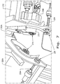
- FIG. 7 is a perspective view illustrating a connection between the center section and the additional section in accordance with an exemplary embodiment of the present invention.
- FIG. 8 is a front view of the folding corn header in a partial harvesting position in accordance with an exemplary embodiment of the present invention.
- FIG. 9 is a front view of the folding corn header in another partial harvesting position in accordance with an exemplary embodiment of the present invention.
- FIG. 10 is a perspective view of the folding corn header in a folded position in accordance with an exemplary embodiment of the present invention.
- FIG. 11 is a schematic representation of an agricultural vehicle with a folding header including a chopper in accordance with another exemplary embodiment of the present invention.
- a conventional agricultural vehicle 100 in the form of a combine harvester which generally includes a chassis 102 , a feeder house 104 , and a known corn header 120 carried by the chassis 102 .
- the corn header 120 includes a frame 122 , snouts 124 , a conveyor 126 , e.g. an auger, and row units 128 .
- the snouts 124 in part define a crop receiving slot or gap therebetween.
- Each row unit 128 may include gathering chains and/or stalk rolls that are driven by respective gearboxes coupled to a single rotating cross shaft.
- the corn header 120 may also include choppers located underneath the stalk rolls of each row unit 128 that are driven by an additional rotating cross shaft.
- the cross shafts may in turn be driven by the PTO of the agricultural vehicle 100 via respective drivelines that extend to the lateral ends of the corn header 120 .
- the corn stalks are cut from the field and the ears of corn are stripped from the stalks by the motion of the gathering chains and stalk rolls.
- the ears of corn are then gathered by the conveyor 126 and are transported to the center of the header 120 for entry into the feeder house 104 and subsequent processing through the agricultural vehicle 100 .
- the stalks and the remaining MOG are pulled down by the stalk rolls and may be chopped into smaller pieces by the chopper.
- the folding header 200 may be operably coupled to an agricultural vehicle 100 .
- the agricultural vehicle 100 may be in the form of a combine harvester which generally includes a chassis that supports the folding header 200 , a PTO, and additional internal systems for the separation and handling of collected crop material. However, these additional systems are omitted from view for brevity of description. It should be appreciated that the folding header 200 described and illustrated herein does not necessarily need to be included on combine harvesters, but can be incorporated in other agricultural vehicles.
- the folding header 200 generally includes a center section 210 and at least one additional section, for example two additional sections 220 A and 220 B, which are pivotally and operably coupled to the center section 210 at joints 202 A, 202 B.
- the folding header 200 is shown to be in the form of a folding corn header and the sections 210 , 220 A, 220 B may each respectively include snouts 211 , 221 A, 221 B, row units 212 , 222 A, 222 B, and/or a conveyor 213 , 223 A, 223 B, e.g. an auger.
- the center section 210 may have 6-8 rows and the additional sections 220 A, 220 B may have 2-4 rows for harvesting corn.
- the center section 210 is operably coupled to the chassis of the agricultural vehicle 100 .
- the center section 210 includes a pair of lateral ends 214 A, 214 B and a drive assembly 230 for driving the row units 212 , 222 A, 222 B.
- the center section 210 may also include an actuating assembly 215 , which may include one or more lift actuator(s) 216 , for pivoting one or both of the additional sections 220 A, 220 B upwardly.
- the lift actuators 216 may be in the form of hydraulic cylinders 216 that are pivotally connected to the additional sections 220 A, 220 B by mounts 217 .
- the actuating assembly 215 may also include various hydraulic and/or electrical lines which are operably coupled to the agricultural vehicle 100 to pivot the additional sections 220 A, 220 B.
- the center conveyor 213 which may be in the form of an auger, may be driven by one or more actuators 218 .
- the actuator(s) 218 may be in the form of a hydraulic or electric motor which is mounted to the center section 210 such that the center conveyor 213 drives the conveyors 223 A, 223 B of the additional sections 220 A, 220 B.
- the center section 210 may include a single actuator 218 in the form of a drive sprocket 218 with an accompanying chain to rotate a gearwheel operably coupled to the center conveyor 213 in order to drive the center conveyor 213 (the chain and chain guard are not shown).
- the center conveyor 213 may selectively couple with the conveyors 223 A, 223 B of the additional sections 220 A, 220 B via self-engaging and corresponding end couplers 219 affixed to the mating ends of the conveyors 213 , 223 A, 223 B ( FIG. 7 ).
- the end couplers 219 are configured to translate the rotational motion of the center conveyor 213 to the additional conveyors 223 A, 223 B.
- the hydraulic cylinders 216 lift a respective additional section 220 A, 220 B the couplers 219 disengage and the additional conveyor 223 A, 223 B of the lifted additional section 220 A, 220 B is no longer in an operational state.
- the drive assembly 230 is operably coupled to the PTO of the agricultural vehicle 100 .
- the drive assembly 230 includes first and second drive lines 232 A, 232 B, first and second transmissions 234 A, 234 B respectively coupled to the first and second drive lines 232 A, 232 B, and a rotating cross shaft 236 .
- the transmissions 234 A, 234 B may be in the form of gearboxes, continuously variable transmissions, chain cases, or any combination thereof.
- the connections between the transmissions 234 A, 234 B and the respective drive lines 232 A, 232 B may be in the form of universal joints or the like.
- the first drive line 232 A is operably coupled to the PTO of the agricultural vehicle 100 , and the first drive line 232 A extends outward to couple to the first, intermediate transmission 234 A.
- the first transmission 234 A is located at a lateral end, for example end 214 A, of the center section 210 .
- the second drive line 232 B is operably coupled to the first transmission 234 A and extends forwardly and inwardly to the bottom center of the center section 210 to couple to the second transmission 234 B.
- the second transmission 234 B is located in between the lateral ends 214 A, 214 B of the center section 210 such that it is approximately located in a middle region of both the center section 210 and the cross shaft 236 .
- the second transmission 234 B is operably coupled to the cross shaft 236 , which in turn drives the row units of the center section 210 .
- the additional sections 220 A, 220 B each have a respective inboard end 224 A, 224 B and a distal end.
- the inboard ends 224 A, 224 B of the additional sections 220 A, 220 B are pivotally coupled to the lateral ends 214 A, 214 B of the center section 210 at joints 202 A, 202 B.
- the additional sections 220 A, 220 B may also include a respective cross shaft 226 A, 226 B for driving their respective row units 222 A, 222 B.
- the respective connections of the cross shafts 226 A, 226 B and the center cross shaft 236 may each include self-engaging end couplers 238 , which selectively engage and disengage with another such that the rotational movement of the cross shaft 236 may or may not be translated to the cross shafts 226 A, 226 B ( FIG. 7 ).
- the respective conveyors 223 A, 223 B and the cross shafts 226 A, 226 B of the additional sections 220 A, 220 B are removably coupled to the center conveyor 213 and cross shaft 236 of the center section 210 , respectively.
- the drive assembly 230 and actuator(s) 218 of the center section 210 drive the row units 222 A, 222 B and the conveyors 223 A, 223 B of the additional sections 220 A, 220 B.
- FIGS. 4 and 8-10 there is shown the folding header 200 throughout several different complete harvesting and partial harvesting positions as a result of selectively pivoting the additional sections 220 A, 220 B between an operational position and a nonoperational position.
- FIG. 4 illustrates the complete harvesting position in which both of the additional sections 220 A, 220 B are driven by the center section 210 .
- the folding header 200 may also be operated in a partial operating state such that one ( FIG. 8 ) or both of the additional sections 220 A, 220 B ( FIG. 9 ) are in a nonoperational position.
- the center section 210 may continue to harvest a crop material as one or both of the additional sections 220 A, 220 B are pivoted upwardly out of the way of the unharvested crop material as well as clear from obstructing the line of sight of the operator. Additionally, the folding header 200 may be folded in a transport position ( FIG. 10 ).
- the center section 210 can harvest the crop material when one or both additional sections 220 A, 220 B are in the nonoperational position, as the row units 222 A, 222 B and conveyors 213 , 223 A, 223 B of each section 210 , 220 A, 220 B are driven from the center section 210 .
- the center cross shaft 236 may continually be driven by the drive assembly 230 as one or both of the cross shafts 226 A, 226 B respectively engage and disengage with the center cross shaft 236 in the operational position and nonoperational position.
- an operator may selectively choose to harvest a lesser or greater amount of crop material by positioning the additional sections 220 A, 220 B in the nonoperational position or by positioning the additional sections 220 A, 220 B in the operational position to use the sections 210 , 220 A, 220 B in conjunction with each other.
- an operator can regulate how much crop material is harvested in order to traverse a greater distance across the field without reaching the maximum capacity of the grain tank of the agricultural vehicle 100 .
- the folding header 200 may initially be transported to a field in the transport position ( FIG. 10 ). Then, an operator may position one or both of the additional sections 220 A, 220 B in the operational position of the additional section(s) 220 A, 220 B. For example, the folding header 200 may be positioned in the complete harvesting position such that both of the additional sections 220 A, 220 B are in their operational positions and are driven by the center section 210 . In the operational position of the additional section(s) 220 A, 220 B a greater amount of crop material may be harvested by the folding header 200 , comparatively to the nonoperational position. An operator may then position the folding header 200 in the partial harvesting position such that one or both of the additional section(s) 220 A, 220 B are positioned in their respective nonoperational position to harvest a lesser amount of crop material.
- the nonoperational position may be a partially lifted position in which one or both of the additional sections 220 A, 220 B are folded upwardly and substantially above the center section 210 .
- the nonoperational position may include any position in which the additional sections 220 A, 220 B are not engaged with the center section 210 , i.e., the respective end couplers 219 , 238 are disengaged.
- the nonoperational position may include a partially folded position in which one or both of the additional sections 220 A, 220 B are folded upward 15°, 30°, 90°, or 120° relative to the horizontal plane of the center section 210 .
- the nonoperational position may further include any position in which the additional sections 220 A, 220 B do not harvest or otherwise interfere with the standing, unharvested rows of crop material.
- FIG. 11 there is shown a schematic illustration of a folding header 300 according to an exemplary embodiment of the present invention.
- the folding header 300 may be substantially similar to the folding header 200 except that the folding header 300 may include the addition of choppers in order to further facilitate the incorporation of the remaining MOG in subsequent tillage practices.
- the folding header 300 may be operably coupled to an agricultural vehicle 100 and supported by its chassis as discussed above.
- the folding header 300 generally includes a center section 310 and at least one additional section, for example two additional sections 320 A and 320 B, which are pivotally and operably coupled to the center section 310 at pivot joints 302 A, 302 B.
- the folding header 300 is in the form of a folding corn header, such that the sections 310 , 320 A, 320 B may each include snouts, row units, choppers and/or a respective conveyor, e.g. an auger.
- the center section 310 may include a pair of lateral ends 312 A, 312 B and two drive assemblies 330 , 340 for respectively driving the row units and choppers. As discussed above, the center section 310 may also include an actuating system and an actuator for respectively pivoting the additional sections 320 A, 320 B and driving the respective conveyors.
- the drive assemblies 330 , 340 of the center section 310 are each operably coupled to the PTO of the agricultural vehicle 100 .
- the drive assemblies 330 , 340 each include respective first and second drive lines 332 A, 332 B and 342 A, 342 B, first and second transmissions 334 , 336 and 344 , 346 , and a rotating cross shaft 338 , 348 .
- the drive assemblies 330 , 340 may be in a similar form and operate as the drive assembly 230 of the folding header 200 described above. Thereby, the first and second drive assembles 330 , 340 can respectively drive the row units and choppers of the center section 310 .
- the additional sections 320 A, 320 B each have a respective inboard end 322 A, 322 B and a distal end.
- the inboard ends 322 A, 322 B of the additional sections 320 A, 320 B are pivotally coupled to the lateral ends 312 A, 312 B of the center section 310 at pivot joints 302 A, 302 B.
- the additional sections 320 A, 320 B may also each include cross shafts 324 A, 324 B and 326 A, 326 B for respectively driving the row units and choppers.
- the respective cross shafts 324 A, 324 B and 326 A, 326 B of the additional sections 320 A, 320 B are removably coupled to the cross shafts 338 and 348 of the center section 310 via self-engaging drive couplers 339 A, 339 B and 349 A, 349 B as described above.
- the center section 310 drives the respective row units, choppers, and conveyors of the additional sections 320 A, 320 B through its drive assemblies 330 , 340 and actuator(s).
- the additional sections 320 A, 320 B of the folding header 300 may selectively and individually pivot between an operational position and a nonoperational position.
- an operator may selectively choose to harvest a greater amount of crop material by using the sections 310 , 320 A, 320 B in conjunction, or may choose to harvest a lesser amount of crop material by placing one or both of the additional sections 320 A, 320 B in the nonoperational position.
Landscapes
- Life Sciences & Earth Sciences (AREA)
- Environmental Sciences (AREA)
- Agricultural Machines (AREA)
- Harvesting Machines For Specific Crops (AREA)
Abstract
Description
Claims (16)
Priority Applications (3)
| Application Number | Priority Date | Filing Date | Title |
|---|---|---|---|
| US15/671,782 US10820509B2 (en) | 2017-08-08 | 2017-08-08 | Foldable corn head |
| EP18185996.8A EP3440918B1 (en) | 2017-08-08 | 2018-07-27 | Foldable corn head |
| CN201810893521.2A CN109379981B (en) | 2017-08-08 | 2018-08-08 | Foldable corn cutting head |
Applications Claiming Priority (1)
| Application Number | Priority Date | Filing Date | Title |
|---|---|---|---|
| US15/671,782 US10820509B2 (en) | 2017-08-08 | 2017-08-08 | Foldable corn head |
Publications (2)
| Publication Number | Publication Date |
|---|---|
| US20190045709A1 US20190045709A1 (en) | 2019-02-14 |
| US10820509B2 true US10820509B2 (en) | 2020-11-03 |
Family
ID=63079789
Family Applications (1)
| Application Number | Title | Priority Date | Filing Date |
|---|---|---|---|
| US15/671,782 Active US10820509B2 (en) | 2017-08-08 | 2017-08-08 | Foldable corn head |
Country Status (3)
| Country | Link |
|---|---|
| US (1) | US10820509B2 (en) |
| EP (1) | EP3440918B1 (en) |
| CN (1) | CN109379981B (en) |
Cited By (6)
| Publication number | Priority date | Publication date | Assignee | Title |
|---|---|---|---|---|
| US20210092902A1 (en) * | 2019-09-30 | 2021-04-01 | Deere & Company | Combine header with split augers and method of using the same |
| US20220015293A1 (en) * | 2020-07-17 | 2022-01-20 | Deere & Company | Folding harvester with crop divider lift and frame lock |
| US20240122120A1 (en) * | 2022-10-13 | 2024-04-18 | Deere & Company | Biasing support member for a row unit point assembly |
| US20250212719A1 (en) * | 2023-12-27 | 2025-07-03 | Cnh Industrial America Llc | Hydraulic auger drive using cutter bar to drive hydraulic pump |
| US20250366393A1 (en) * | 2024-06-04 | 2025-12-04 | Deere & Company | Foldable harvesting machine implement |
| US12565914B2 (en) | 2022-12-09 | 2026-03-03 | Cnh Industrial America Llc | Power transfer arrangement including coupling clutches for an agricultural vehicle |
Families Citing this family (11)
| Publication number | Priority date | Publication date | Assignee | Title |
|---|---|---|---|---|
| US10537063B2 (en) * | 2017-10-11 | 2020-01-21 | Deere & Company | Folding agricultural head |
| US10426088B2 (en) | 2017-10-11 | 2019-10-01 | Deere & Company | Center feed assembly for a draper |
| US10433486B2 (en) | 2017-10-16 | 2019-10-08 | Deere & Company | System and method for wing float on a combine draper header |
| US10568266B2 (en) | 2017-10-17 | 2020-02-25 | Deere & Company | Self-contained combine draper wing leveler |
| US10813289B2 (en) * | 2018-06-05 | 2020-10-27 | Deere & Company | Single top beam folding corn head mainframe |
| US10703277B1 (en) | 2019-05-16 | 2020-07-07 | Cnh Industrial America Llc | Heads-up display for an agricultural combine |
| US11425860B2 (en) | 2019-10-22 | 2022-08-30 | Cnh Industrial America Llc | Auger and drive assembly for an agricultural harvester header |
| US11490568B2 (en) * | 2020-03-11 | 2022-11-08 | Deere & Company | Pivoting apparatus for row head |
| US11785890B2 (en) * | 2020-06-17 | 2023-10-17 | Deere & Company | Corn head adjustment system with integrated actuation |
| US12114602B2 (en) * | 2020-06-17 | 2024-10-15 | Deere & Company | Corn head adjustment system with force relief |
| EP4312501B1 (en) * | 2021-03-29 | 2025-10-22 | MacDon Industries Ltd. | Flexing header with float system |
Citations (29)
| Publication number | Priority date | Publication date | Assignee | Title |
|---|---|---|---|---|
| US4227366A (en) * | 1979-08-06 | 1980-10-14 | Sperry Corporation | Corn header drive system |
| US4300333A (en) * | 1980-07-18 | 1981-11-17 | Deere & Company | Auger conveyor for a crop harvester |
| US4409780A (en) | 1982-03-11 | 1983-10-18 | Kansas State University Research Foundation | Folding header assembly |
| FR2685162A1 (en) | 1991-12-20 | 1993-06-25 | Bourgoin Ets J | Foldable picker device for harvesting maize or similar plants |
| US5673543A (en) * | 1996-01-04 | 1997-10-07 | Byron Enterprises, Inc | Foldable corn head with unobstructed auger |
| US5724798A (en) * | 1996-07-08 | 1998-03-10 | Byron Enterprises Inc. | Latch for a folding corn head |
| US5845472A (en) * | 1995-06-27 | 1998-12-08 | Claas Kgaa | Harvesting attachment for agricultural machines for picking and transporting stalk crops, in particular corn plants |
| US20030074876A1 (en) * | 2001-06-18 | 2003-04-24 | Patterson Roger L. | Multi-section header with flexible crop cutting knife |
| US20030182912A1 (en) * | 2002-03-28 | 2003-10-02 | Claas Saulgau Gmbh | Mower for attaching onto a carrier machine |
| EP1362504A1 (en) | 2002-05-17 | 2003-11-19 | Maschinenfabrik Kemper GmbH & Co. KG | Machine for mowing stalk crops |
| US20040123575A1 (en) * | 2002-10-29 | 2004-07-01 | Clemens Rickert | Adjusting device for a harvesting attachment |
| US20050109001A1 (en) * | 2003-11-25 | 2005-05-26 | Deere & Company, A Delaware Corporation | Transverse conveying auger for a harvesting head |
| US7043889B2 (en) * | 2003-01-29 | 2006-05-16 | Claas Saulgau Gmbh | Machine for harvesting stalk crops |
| US7073604B1 (en) * | 2005-02-22 | 2006-07-11 | Morris Industries Ltd. | Hydraulic holding cylinder for wing lift mechanism |
| US7234291B2 (en) * | 2003-01-24 | 2007-06-26 | Deere & Company | Drive train for a header of a harvesting machine |
| US20080072560A1 (en) * | 2006-09-25 | 2008-03-27 | Talbot Francois R | Device for maintaining wing balance on a multi-section header |
| US20080295473A1 (en) * | 2007-06-04 | 2008-12-04 | Claas Selbstfahrende Erntemaschinen Gmbh | Winged header apparatus and method for a combine |
| US7937918B1 (en) | 2010-08-27 | 2011-05-10 | Deere & Company | Drive arrangement for corn head equipped with or without a corn stalk chopper |
| EP2446729A1 (en) | 2010-10-27 | 2012-05-02 | Olimac S.r.l. | A machine for harvesting maize |
| US8635842B2 (en) * | 2009-08-05 | 2014-01-28 | Kevin Markt | Flexible row crop header for an agricultural harvester |
| US20140033670A1 (en) * | 2012-08-06 | 2014-02-06 | F.Lli Cressoni S.P.A. | Folding heads for corn-shelling machines and combine harvesters |
| US20140066149A1 (en) * | 2012-08-31 | 2014-03-06 | Cnh America Llc | Auger Drive Coupler Assembly for a Combine Harvester |
| US20140075906A1 (en) * | 2012-09-20 | 2014-03-20 | Deere & Company | Hinged row crop auger conveyor |
| US20140075907A1 (en) * | 2012-09-20 | 2014-03-20 | Deere & Company | Hinged row crop harvesting head |
| US20140075909A1 (en) * | 2012-09-20 | 2014-03-20 | Deere & Company | Self-centering cover for hinged row crop harvesting head |
| US9072221B2 (en) | 2013-03-21 | 2015-07-07 | Deere & Company | Sectional driveshaft arrangement for a corn head |
| EP2995188A1 (en) | 2014-09-15 | 2016-03-16 | CNH Industrial Belgium nv | Power takeoff drive assembly for a corn header of an agricultural harvester |
| WO2017120343A1 (en) | 2016-01-05 | 2017-07-13 | Oxbo International Corporation | Integrated lift and frame lock for a folding corn head row separator |
| US9723783B2 (en) * | 2012-05-29 | 2017-08-08 | Cnh Industrial America Llc | Folding auger assembly coupler |
Family Cites Families (4)
| Publication number | Priority date | Publication date | Assignee | Title |
|---|---|---|---|---|
| NL6414183A (en) * | 1964-12-05 | 1966-06-06 | ||
| NL6903371A (en) * | 1969-03-05 | 1970-09-08 | ||
| CN204907169U (en) * | 2015-07-02 | 2015-12-30 | 济南大学 | Folding maize header |
| CN106258222A (en) * | 2016-10-17 | 2017-01-04 | 济南大学 | A kind of ceding of Taiwan fold mechanism |
-
2017
- 2017-08-08 US US15/671,782 patent/US10820509B2/en active Active
-
2018
- 2018-07-27 EP EP18185996.8A patent/EP3440918B1/en active Active
- 2018-08-08 CN CN201810893521.2A patent/CN109379981B/en active Active
Patent Citations (36)
| Publication number | Priority date | Publication date | Assignee | Title |
|---|---|---|---|---|
| US4227366A (en) * | 1979-08-06 | 1980-10-14 | Sperry Corporation | Corn header drive system |
| US4300333A (en) * | 1980-07-18 | 1981-11-17 | Deere & Company | Auger conveyor for a crop harvester |
| US4409780A (en) | 1982-03-11 | 1983-10-18 | Kansas State University Research Foundation | Folding header assembly |
| FR2685162A1 (en) | 1991-12-20 | 1993-06-25 | Bourgoin Ets J | Foldable picker device for harvesting maize or similar plants |
| US5845472A (en) * | 1995-06-27 | 1998-12-08 | Claas Kgaa | Harvesting attachment for agricultural machines for picking and transporting stalk crops, in particular corn plants |
| US5673543A (en) * | 1996-01-04 | 1997-10-07 | Byron Enterprises, Inc | Foldable corn head with unobstructed auger |
| US5724798A (en) * | 1996-07-08 | 1998-03-10 | Byron Enterprises Inc. | Latch for a folding corn head |
| US20030074876A1 (en) * | 2001-06-18 | 2003-04-24 | Patterson Roger L. | Multi-section header with flexible crop cutting knife |
| US20030182912A1 (en) * | 2002-03-28 | 2003-10-02 | Claas Saulgau Gmbh | Mower for attaching onto a carrier machine |
| US20030226342A1 (en) * | 2002-05-17 | 2003-12-11 | Norbert Boeckmann | Harvesting header |
| EP1362504A1 (en) | 2002-05-17 | 2003-11-19 | Maschinenfabrik Kemper GmbH & Co. KG | Machine for mowing stalk crops |
| US20040123575A1 (en) * | 2002-10-29 | 2004-07-01 | Clemens Rickert | Adjusting device for a harvesting attachment |
| US7234291B2 (en) * | 2003-01-24 | 2007-06-26 | Deere & Company | Drive train for a header of a harvesting machine |
| US7043889B2 (en) * | 2003-01-29 | 2006-05-16 | Claas Saulgau Gmbh | Machine for harvesting stalk crops |
| US20050109001A1 (en) * | 2003-11-25 | 2005-05-26 | Deere & Company, A Delaware Corporation | Transverse conveying auger for a harvesting head |
| US7073604B1 (en) * | 2005-02-22 | 2006-07-11 | Morris Industries Ltd. | Hydraulic holding cylinder for wing lift mechanism |
| US20080072560A1 (en) * | 2006-09-25 | 2008-03-27 | Talbot Francois R | Device for maintaining wing balance on a multi-section header |
| US20080295473A1 (en) * | 2007-06-04 | 2008-12-04 | Claas Selbstfahrende Erntemaschinen Gmbh | Winged header apparatus and method for a combine |
| US8635842B2 (en) * | 2009-08-05 | 2014-01-28 | Kevin Markt | Flexible row crop header for an agricultural harvester |
| US9801343B2 (en) * | 2009-08-05 | 2017-10-31 | Kevin Markt | Flexible row crop header for an agricultural harvester |
| US7937918B1 (en) | 2010-08-27 | 2011-05-10 | Deere & Company | Drive arrangement for corn head equipped with or without a corn stalk chopper |
| EP2446729A1 (en) | 2010-10-27 | 2012-05-02 | Olimac S.r.l. | A machine for harvesting maize |
| US9723783B2 (en) * | 2012-05-29 | 2017-08-08 | Cnh Industrial America Llc | Folding auger assembly coupler |
| US9173345B2 (en) * | 2012-08-06 | 2015-11-03 | F.Lli Cressoni S.P.A. | Folding heads for corn-shelling machines and combine harvesters |
| EP2695509A1 (en) | 2012-08-06 | 2014-02-12 | F.LLI CRESSONI SpA | Folding head for a corn-shelling machine and/or combine harvester and method of folding back a head for a corn-shelling machine and/or combine harvester |
| US20140033670A1 (en) * | 2012-08-06 | 2014-02-06 | F.Lli Cressoni S.P.A. | Folding heads for corn-shelling machines and combine harvesters |
| US20140066149A1 (en) * | 2012-08-31 | 2014-03-06 | Cnh America Llc | Auger Drive Coupler Assembly for a Combine Harvester |
| US9198355B2 (en) * | 2012-09-20 | 2015-12-01 | Deere & Company | Hinged row crop auger conveyor |
| US9198353B2 (en) * | 2012-09-20 | 2015-12-01 | Deere & Company | Hinged row crop harvesting head |
| US20140075909A1 (en) * | 2012-09-20 | 2014-03-20 | Deere & Company | Self-centering cover for hinged row crop harvesting head |
| US20140075907A1 (en) * | 2012-09-20 | 2014-03-20 | Deere & Company | Hinged row crop harvesting head |
| US20140075906A1 (en) * | 2012-09-20 | 2014-03-20 | Deere & Company | Hinged row crop auger conveyor |
| US9072221B2 (en) | 2013-03-21 | 2015-07-07 | Deere & Company | Sectional driveshaft arrangement for a corn head |
| EP2995188A1 (en) | 2014-09-15 | 2016-03-16 | CNH Industrial Belgium nv | Power takeoff drive assembly for a corn header of an agricultural harvester |
| US20160073585A1 (en) | 2014-09-15 | 2016-03-17 | Cnh Industrial America Llc | Power takeoff drive assembly for a corn header of an agricultural harvester |
| WO2017120343A1 (en) | 2016-01-05 | 2017-07-13 | Oxbo International Corporation | Integrated lift and frame lock for a folding corn head row separator |
Non-Patent Citations (1)
| Title |
|---|
| European Search Report for European Patent Application No. 18185996.8 dated Dec. 7, 2018 (6 pages). |
Cited By (8)
| Publication number | Priority date | Publication date | Assignee | Title |
|---|---|---|---|---|
| US20210092902A1 (en) * | 2019-09-30 | 2021-04-01 | Deere & Company | Combine header with split augers and method of using the same |
| US11758850B2 (en) * | 2019-09-30 | 2023-09-19 | Deere & Company | Combine header with split augers and method of using the same |
| US20220015293A1 (en) * | 2020-07-17 | 2022-01-20 | Deere & Company | Folding harvester with crop divider lift and frame lock |
| US11570950B2 (en) * | 2020-07-17 | 2023-02-07 | Deere & Company | Folding harvester with crop divider lift and frame lock |
| US20240122120A1 (en) * | 2022-10-13 | 2024-04-18 | Deere & Company | Biasing support member for a row unit point assembly |
| US12565914B2 (en) | 2022-12-09 | 2026-03-03 | Cnh Industrial America Llc | Power transfer arrangement including coupling clutches for an agricultural vehicle |
| US20250212719A1 (en) * | 2023-12-27 | 2025-07-03 | Cnh Industrial America Llc | Hydraulic auger drive using cutter bar to drive hydraulic pump |
| US20250366393A1 (en) * | 2024-06-04 | 2025-12-04 | Deere & Company | Foldable harvesting machine implement |
Also Published As
| Publication number | Publication date |
|---|---|
| US20190045709A1 (en) | 2019-02-14 |
| EP3440918A1 (en) | 2019-02-13 |
| CN109379981A (en) | 2019-02-26 |
| EP3440918B1 (en) | 2022-05-04 |
| CN109379981B (en) | 2022-06-07 |
Similar Documents
| Publication | Publication Date | Title |
|---|---|---|
| US10820509B2 (en) | Foldable corn head | |
| US10327386B2 (en) | Header for an agricultural harvester with independent sub-system drives | |
| US10820519B2 (en) | Agricultural chopper with linked counter knives and shear bar | |
| US10653069B2 (en) | Residue handling system for an agricultural harvester | |
| EP3066910A1 (en) | Folding mechanism for wide wheat headers | |
| EP3424293A1 (en) | Residue management system with a selection door for an agricultural vehicle | |
| US9345198B2 (en) | Residue chopping and distribution arrangement for a combine harvester | |
| US12069988B2 (en) | Adjustable ear dam for a corn header | |
| US20190313581A1 (en) | Tined-Tube Auger | |
| EP3530103B1 (en) | Drive unit for a down crop attachment on a header | |
| EP3516945B1 (en) | Down crop attachment for a header | |
| EP3653040B1 (en) | Reel drive assembly for an agricultural header | |
| EP3603378B1 (en) | Conveyor chain with multi-segment conveying floor | |
| US12279556B2 (en) | Dual variable feeder drive for agricultural vehicle | |
| US12439850B2 (en) | Floating floor assembly of a header |
Legal Events
| Date | Code | Title | Description |
|---|---|---|---|
| AS | Assignment |
Owner name: CNH INDUSTRIAL AMERICA LLC, PENNSYLVANIA Free format text: ASSIGNMENT OF ASSIGNORS INTEREST;ASSIGNORS:SCHROEDER, JAY D.;LUKAC, JOHN BRADLEY;DUQUESNE, FRANK R.G.;AND OTHERS;SIGNING DATES FROM 20170622 TO 20170808;REEL/FRAME:043233/0055 |
|
| STPP | Information on status: patent application and granting procedure in general |
Free format text: NON FINAL ACTION MAILED |
|
| STCB | Information on status: application discontinuation |
Free format text: ABANDONED -- FAILURE TO RESPOND TO AN OFFICE ACTION |
|
| STPP | Information on status: patent application and granting procedure in general |
Free format text: NON FINAL ACTION MAILED |
|
| STPP | Information on status: patent application and granting procedure in general |
Free format text: FINAL REJECTION MAILED |
|
| STPP | Information on status: patent application and granting procedure in general |
Free format text: ADVISORY ACTION MAILED |
|
| STPP | Information on status: patent application and granting procedure in general |
Free format text: DOCKETED NEW CASE - READY FOR EXAMINATION |
|
| STPP | Information on status: patent application and granting procedure in general |
Free format text: NOTICE OF ALLOWANCE MAILED -- APPLICATION RECEIVED IN OFFICE OF PUBLICATIONS |
|
| AS | Assignment |
Owner name: CNH INDUSTRIAL AMERICA LLC, PENNSYLVANIA Free format text: ASSIGNMENT OF ASSIGNORS INTEREST;ASSIGNOR:CNH INDUSTRIAL BELGIUM NV;REEL/FRAME:053793/0705 Effective date: 20170808 Owner name: CNH INDUSTRIAL BELGIUM NV, BELGIUM Free format text: ASSIGNMENT OF ASSIGNORS INTEREST;ASSIGNOR:DUQUESNE, FRANK R.G.;REEL/FRAME:053793/0658 Effective date: 20170808 |
|
| STCF | Information on status: patent grant |
Free format text: PATENTED CASE |
|
| AS | Assignment |
Owner name: BLUE LEAF I.P., INC., DELAWARE Free format text: ASSIGNMENT OF ASSIGNORS INTEREST;ASSIGNOR:CNH INDUSTRIAL AMERICA LLC;REEL/FRAME:055343/0448 Effective date: 20210205 |
|
| MAFP | Maintenance fee payment |
Free format text: PAYMENT OF MAINTENANCE FEE, 4TH YEAR, LARGE ENTITY (ORIGINAL EVENT CODE: M1551); ENTITY STATUS OF PATENT OWNER: LARGE ENTITY Year of fee payment: 4 |