US10819899B2 - Image acquisition device and image acquisition system - Google Patents
Image acquisition device and image acquisition system Download PDFInfo
- Publication number
- US10819899B2 US10819899B2 US16/679,890 US201916679890A US10819899B2 US 10819899 B2 US10819899 B2 US 10819899B2 US 201916679890 A US201916679890 A US 201916679890A US 10819899 B2 US10819899 B2 US 10819899B2
- Authority
- US
- United States
- Prior art keywords
- image
- light receiving
- microlenses
- unit
- arrangement state
- Prior art date
- Legal status (The legal status is an assumption and is not a legal conclusion. Google has not performed a legal analysis and makes no representation as to the accuracy of the status listed.)
- Active
Links
Images


Classifications
-
- H04N5/23212—
-
- H—ELECTRICITY
- H04—ELECTRIC COMMUNICATION TECHNIQUE
- H04N—PICTORIAL COMMUNICATION, e.g. TELEVISION
- H04N23/00—Cameras or camera modules comprising electronic image sensors; Control thereof
- H04N23/60—Control of cameras or camera modules
- H04N23/67—Focus control based on electronic image sensor signals
-
- G—PHYSICS
- G02—OPTICS
- G02B—OPTICAL ELEMENTS, SYSTEMS OR APPARATUS
- G02B3/00—Simple or compound lenses
- G02B3/0006—Arrays
- G02B3/0037—Arrays characterized by the distribution or form of lenses
-
- G—PHYSICS
- G03—PHOTOGRAPHY; CINEMATOGRAPHY; ANALOGOUS TECHNIQUES USING WAVES OTHER THAN OPTICAL WAVES; ELECTROGRAPHY; HOLOGRAPHY
- G03B—APPARATUS OR ARRANGEMENTS FOR TAKING PHOTOGRAPHS OR FOR PROJECTING OR VIEWING THEM; APPARATUS OR ARRANGEMENTS EMPLOYING ANALOGOUS TECHNIQUES USING WAVES OTHER THAN OPTICAL WAVES; ACCESSORIES THEREFOR
- G03B17/00—Details of cameras or camera bodies; Accessories therefor
- G03B17/02—Bodies
- G03B17/12—Bodies with means for supporting objectives, supplementary lenses, filters, masks, or turrets
- G03B17/14—Bodies with means for supporting objectives, supplementary lenses, filters, masks, or turrets interchangeably
-
- H—ELECTRICITY
- H04—ELECTRIC COMMUNICATION TECHNIQUE
- H04N—PICTORIAL COMMUNICATION, e.g. TELEVISION
- H04N23/00—Cameras or camera modules comprising electronic image sensors; Control thereof
- H04N23/60—Control of cameras or camera modules
- H04N23/66—Remote control of cameras or camera parts, e.g. by remote control devices
- H04N23/663—Remote control of cameras or camera parts, e.g. by remote control devices for controlling interchangeable camera parts based on electronic image sensor signals
-
- H—ELECTRICITY
- H04—ELECTRIC COMMUNICATION TECHNIQUE
- H04N—PICTORIAL COMMUNICATION, e.g. TELEVISION
- H04N23/00—Cameras or camera modules comprising electronic image sensors; Control thereof
- H04N23/95—Computational photography systems, e.g. light-field imaging systems
- H04N23/957—Light-field or plenoptic cameras or camera modules
-
- H—ELECTRICITY
- H04—ELECTRIC COMMUNICATION TECHNIQUE
- H04N—PICTORIAL COMMUNICATION, e.g. TELEVISION
- H04N23/00—Cameras or camera modules comprising electronic image sensors; Control thereof
- H04N23/95—Computational photography systems, e.g. light-field imaging systems
- H04N23/958—Computational photography systems, e.g. light-field imaging systems for extended depth of field imaging
-
- H04N5/23209—
-
- G—PHYSICS
- G02—OPTICS
- G02B—OPTICAL ELEMENTS, SYSTEMS OR APPARATUS
- G02B27/00—Optical systems or apparatus not provided for by any of the groups G02B1/00 - G02B26/00, G02B30/00
- G02B27/0075—Optical systems or apparatus not provided for by any of the groups G02B1/00 - G02B26/00, G02B30/00 with means for altering, e.g. increasing, the depth of field or depth of focus
-
- G—PHYSICS
- G03—PHOTOGRAPHY; CINEMATOGRAPHY; ANALOGOUS TECHNIQUES USING WAVES OTHER THAN OPTICAL WAVES; ELECTROGRAPHY; HOLOGRAPHY
- G03B—APPARATUS OR ARRANGEMENTS FOR TAKING PHOTOGRAPHS OR FOR PROJECTING OR VIEWING THEM; APPARATUS OR ARRANGEMENTS EMPLOYING ANALOGOUS TECHNIQUES USING WAVES OTHER THAN OPTICAL WAVES; ACCESSORIES THEREFOR
- G03B13/00—Viewfinders; Focusing aids for cameras; Means for focusing for cameras; Autofocus systems for cameras
- G03B13/32—Means for focusing
- G03B13/34—Power focusing
-
- G—PHYSICS
- G03—PHOTOGRAPHY; CINEMATOGRAPHY; ANALOGOUS TECHNIQUES USING WAVES OTHER THAN OPTICAL WAVES; ELECTROGRAPHY; HOLOGRAPHY
- G03B—APPARATUS OR ARRANGEMENTS FOR TAKING PHOTOGRAPHS OR FOR PROJECTING OR VIEWING THEM; APPARATUS OR ARRANGEMENTS EMPLOYING ANALOGOUS TECHNIQUES USING WAVES OTHER THAN OPTICAL WAVES; ACCESSORIES THEREFOR
- G03B2205/00—Adjustment of optical system relative to image or object surface other than for focusing
- G03B2205/0053—Driving means for the movement of one or more optical element
-
- G—PHYSICS
- G03—PHOTOGRAPHY; CINEMATOGRAPHY; ANALOGOUS TECHNIQUES USING WAVES OTHER THAN OPTICAL WAVES; ELECTROGRAPHY; HOLOGRAPHY
- G03B—APPARATUS OR ARRANGEMENTS FOR TAKING PHOTOGRAPHS OR FOR PROJECTING OR VIEWING THEM; APPARATUS OR ARRANGEMENTS EMPLOYING ANALOGOUS TECHNIQUES USING WAVES OTHER THAN OPTICAL WAVES; ACCESSORIES THEREFOR
- G03B35/00—Stereoscopic photography
Definitions
- the present invention relates to an image acquisition device and an image acquisition system.
- light-field image acquisition devices that include an image acquisition element in which a plurality of pixels are two-dimensionally arranged, and a microlens array having microlenses arranged on the subject side with respect to the image acquisition element so as to correspond to units of pixels of the image acquisition element; and that acquire an image of a three-dimensional distribution of the subject (refer to, for example, Japanese Unexamined Patent Application, Publication No. 2010-102230).
- the camera and microscope can provide, with a simple configuration, images such as light-field images that produce, from the same subject, different effects from those of normally acquired images (images that produce different effects from those of such normally acquired images are referred to as, for example, functional images).
- images such as light-field images that produce, from the same subject, different effects from those of normally acquired images (images that produce different effects from those of such normally acquired images are referred to as, for example, functional images).
- devices for providing images that produce different effects from those of normally acquired images have a highly specialized configuration, as do conventional light-field image acquisition devices.
- the camera lens adaptor described in Japanese Unexamined Patent Application, Publication No. 2010-102230 allows light-field images to be acquired.
- a first aspect of the present invention is an image acquisition device including: an image-acquisition optical system that focuses light from a subject and that forms a primary image of the subject; a microlens array having a plurality of microlenses that are two-dimensionally arranged at a position of the primary image formed by the image-acquisition optical system or at a position conjugate to the primary image and that focus light from the image-acquisition optical system; a pupil modulation element that is disposed at the position of an exit pupil of the image-acquisition optical system, said exit pupil being located on the subject side with respect to the microlens array, or at a position conjugate to the exit pupil and that applies modulation of a phase distribution and/or a transmittance distribution to light to be made incident on the plurality of microlenses via the image-acquisition optical system; a light receiving unit that has a plurality of light receiving elements arranged in units of regions corresponding to the plurality of microlenses, that receives the light focused by the plurality of microlenses, and that performs photo
- a second aspect of the present invention is an image acquisition system including: an image acquisition device including an image-acquisition optical system that focuses light from a subject and that forms a primary image of the subject, a microlens array having a plurality of microlenses that are two-dimensionally arranged at the position of the primary image formed by the image-acquisition optical system or at a position conjugate to the primary image and that focus light from the image-acquisition optical system, a pupil modulation element that is disposed at the position of an exit pupil of the image-acquisition optical system, said exit pupil being located on the subject side with respect to the microlens array, or at a position conjugate to the exit pupil and that applies modulation of a phase distribution and/or a transmittance distribution to light to be made incident on the plurality of microlenses via the image-acquisition optical system, a light receiving unit that has a plurality of light receiving elements arranged in units of regions corresponding to the plurality of microlenses, that receives the light focused by the plurality of microlenses, and
- FIG. 1 is a schematic configuration diagram of an image acquisition device according to a first embodiment of the present invention.
- FIG. 2 is a flowchart for illustrating the process of acquiring images of a subject by means of the image acquisition device in FIG. 1 .
- FIG. 3 is a flowchart for illustrating first image processing in step SA 4 of the flowchart in FIG. 2 .
- FIG. 4 is a flowchart for illustrating second image processing in step SA 5 of the flowchart in FIG. 2 .
- FIG. 5 is a diagram for illustrating the relationship among the presence/absence of a phase filter, a first point image intensity distribution, and a second point image intensity distribution.
- FIG. 6 is a graph for illustrating analysis using Fisher information.
- FIG. 7 is a schematic configuration diagram of an image acquisition device according to a second embodiment of the present invention.
- FIG. 8 is a diagram depicting one example of refraction of light at microlenses and refraction of light at the projection plane of the microlenses projected by a relay optical system in FIG. 7 .
- FIG. 9 is a diagram depicting one example of an image acquired in a first arrangement state.
- FIG. 10 is a diagram depicting one example of an image acquired in a second arrangement state.
- FIG. 11 is a diagram depicting examples of an image in the case where a plurality of light receiving elements and principal point positions of the microlenses have a conjugate positional relationship and images in the case where the plurality of light receiving elements are slightly shifted from the principal point positions of the microlenses in a direction along an optical axis.
- FIG. 12 is a schematic configuration diagram of an image acquisition device according to a modification of the second embodiment of the present invention.
- FIG. 13 is a schematic configuration diagram of an image acquisition device according to a third embodiment of the present invention.
- FIG. 14 is a schematic configuration diagram of an image acquisition device according to a modification of the third embodiment of the present invention.
- FIG. 15 is a diagram depicting one example of the configuration of an image-acquisition optical system in the case where the image acquisition device according to each of the embodiments of the present invention is incorporated in a microscope.
- FIG. 16 is a diagram depicting another example of the configuration of the image-acquisition optical system in the case where the image acquisition device according to each of the embodiments of the present invention is incorporated in a microscope.
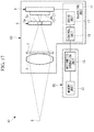
- FIG. 17 is a schematic configuration diagram of an image acquisition system according to a fourth embodiment of the present invention.
- an image acquisition device 1 includes: an image-acquisition optical system 3 for forming a primary image of a subject S by focusing light from the subject S (object point); a microlens array 5 having a plurality of microlenses 5 a that focus the light from the image-acquisition optical system 3 ; a phase filter (pupil modulation element) 7 for performing modulation of a phase distribution of the light that is to be made incident on the plurality of microlenses 5 a via the image-acquisition optical system 3 ; a light receiving unit 9 provided with a plurality of light receiving elements 9 a that receive the light focused by the plurality of microlenses 5 a and that perform photoelectric conversion of the light; an adjusting unit 11 for switching the positional relationship between the plurality of light receiving elements 9 a and the microlens array 5 ; a memory unit 13 for storing point image intensity distributions at the light receiving unit 9 ; and an arithmetic operation unit 15 for generating images.
- an image-acquisition optical system 3 for forming a
- the microlens array 5 is composed of the plurality of microlenses 5 a each having high convexity (positive power) on one surface on the opposite side from the subject S side.
- the plurality of microlenses 5 a are arranged at the position of the primary image formed by the image-acquisition optical system 3 and are two-dimensionally arranged in directions intersecting the optical axis of the image-acquisition optical system 3 .
- the plurality of microlenses 5 a are arranged at sufficiently large pitches, compared with the pitches of the light receiving elements 9 a (e.g., pitches ten times the pitches of the light receiving elements 9 a or more).
- pitches of the light receiving elements 9 a e.g., pitches ten times the pitches of the light receiving elements 9 a or more.
- directions that are orthogonal to the optical axis of the image-acquisition optical system 3 and that are orthogonal to each other are referred to as the X direction and the Y direction, and a direction along the optical axis of the image-acquisition optical system 3 is referred to as the Z direction.
- the phase filter 7 is formed of a glass material.
- the glass material is coated with a polymer whose amount has been adjusted so as to produce a phase delay amount according to, for example, a cubic function in each of the X direction and the Y direction at the pupil of the image-acquisition optical system 3 .
- the phase filter 7 imparts a cubic-function phase distribution to the light having passed through the image-acquisition optical system 3 and extends the depth of field in, for example, normal observation.
- the phase filter 7 can be furnished with a polymer shape exhibiting a desired phase distribution by producing, for example, a mold of the shape reverse to the shape of the phase distribution to be applied and by forming (transferring) the shape.
- a shape having a desired phase distribution may be achieved by directly processing the glass material, including achieving a shape by machining the glass material, forming a rough shape by cutting the glass material and then finishing the shape by polishing, and achieving a shape by grinding the surface of the glass material through, for example, laser processing.
- a polymer shape having a desired phase distribution may be achieved by layering materials with a 3D printer.
- a shape having a desired phase distribution may be achieved by imparting a phase difference by means of a transmissive device, such as a transmissive liquid crystal device, or imparting a phase difference by means of a reflective device, such as an LCOS (Liquid Crystal On Silicon, trademark) device.
- a transmissive device such as a transmissive liquid crystal device
- a reflective device such as an LCOS (Liquid Crystal On Silicon, trademark) device.
- the light receiving unit 9 is disposed so as to be movable in a direction along the optical axis of the image-acquisition optical system 3 .
- the plurality of light receiving elements 9 a are two-dimensionally arranged in directions intersecting the optical axis of the image-acquisition optical system 3 , and a plurality of light receiving elements 9 a are arranged for each region corresponding to a plurality of microlenses 5 a of the microlens array 5 .
- the plurality of light receiving elements 9 a perform photoelectric conversion of detected light and output light intensity signals, serving as image information (first image information and second image information) about the subject S.
- the adjusting unit 11 includes: a drive unit 17 , such as a stepper motor or a piezo actuator, for moving the light receiving unit 9 in a direction along the optical axis of the image-acquisition optical system 3 ; and a control unit 19 for controlling etc. the drive unit 17 .
- a drive unit 17 such as a stepper motor or a piezo actuator, for moving the light receiving unit 9 in a direction along the optical axis of the image-acquisition optical system 3 ; and a control unit 19 for controlling etc. the drive unit 17 .
- control unit 19 includes: a CPU (Central Processing Unit); a main storage unit, such as a ROM (Read Only Memory) and a RAM (Random Access Memory); an auxiliary storage unit, such as an HDD (Hard Disk Drive); an input unit used by a user to input an instruction; an output unit for outputting data; an external interface for exchanging various types of data with external devices (none is shown in the figure), and so on.
- the auxiliary storage unit stores various types of programs, and various types of processing is performed as a result of the CPU reading programs from the auxiliary storage unit into the main storage unit, such as the RAM, and then executing the programs.
- control unit 19 drives the drive unit 17 and switches between a first arrangement state, in which the light receiving unit 9 is disposed at the back focal positions of the microlenses 5 a , and a second arrangement state, in which the light receiving unit 9 is disposed in the vicinities of the principal point positions of the microlenses 5 a .
- a first arrangement state a light-field image can be acquired as a result of the plurality of light receiving elements 9 a being arranged at the back focal positions of the microlenses 5 a .
- a normal two-dimensional image can be acquired as a result of the plurality of light receiving elements 9 a being arranged in the vicinities of the principal point positions of the microlenses 5 a.
- the control unit 19 When the first arrangement state is selected, the control unit 19 inputs, to the arithmetic operation unit 15 , information indicating that the first arrangement state is selected, and when the second arrangement state is selected, the control unit 19 inputs, to the arithmetic operation unit 15 , information indicating that the second arrangement state is selected.
- the control unit 19 sends, to the arithmetic operation unit 15 , the light intensity signals output from the plurality of light receiving elements 9 a of the light receiving unit 9 .
- the memory unit 13 stores a first point image intensity distribution, which indicates a point image intensity distribution for each position on the subject at the light receiving unit 9 in the first arrangement state, and a second point image intensity distribution, which indicates a point image intensity distribution of the subject S at the light receiving unit 9 in the second arrangement state.
- the first point image intensity distribution includes intensity distributions that differ for each position on the subject, whereas the second point image intensity distribution is one distribution that does not depend on the position on the subject.
- the arithmetic operation unit 15 uses the first point image intensity distribution stored in the memory unit 13 and applies predetermined first image processing for generating a light-field processed image (e.g., a 2D slice image or a 3D multislice image) to the light intensity signals sent from the control unit 19 , thus generating a final image (first processed image).
- a light-field processed image e.g., a 2D slice image or a 3D multislice image
- the arithmetic operation unit 15 does not perform the predetermined image processing for generating a light-field processed image but uses the second point image intensity distribution stored in the memory unit 13 and applies second image processing for generating a normal two-dimensional image to the light intensity signals sent from the control unit 19 , thus generating a final image (second processed image).
- first the first arrangement state or the second arrangement state is selected by causing the control unit 19 to drive the drive unit 17 so as to adjust the position of the light receiving unit 9 in a direction along the optical axis of the image-acquisition optical system 3 (step SA 1 ).
- first arrangement state information indicating that the first arrangement state is selected is input from the control unit 19 to the arithmetic operation unit 15 .
- second arrangement state information indicating that the second arrangement state is selected is input from the control unit 19 to the arithmetic operation unit 15 .
- Light from the subject S is focused by the image-acquisition optical system 3 , is incident on the microlens array 5 via the phase filter 7 , and is focused by the plurality of microlenses 5 a of the microlens array 5 . Thereafter, light having passed through each of the microlenses 5 a is received by a plurality of light receiving elements 9 a of the light receiving unit 9 and is then subjected to photoelectric conversion. The light intensity signal produced as a result of the light being subjected to photoelectric conversion by each of the light receiving elements 9 a is sent to the arithmetic operation unit 15 .
- an intensity distribution I m at the light receiving unit 9 is acquired on the basis of the light intensity signals sent from the light receiving unit 9 (step SA 2 ).
- step SA 3 the arithmetic operation unit 15 applies, to the acquired intensity distribution I m , the predetermined first image processing for generating a light-field processed image (step SA 4 ).
- step SA 4 The first image processing in step SA 4 will be described with reference to the flowchart in FIG. 3 .
- the arithmetic operation unit 15 reads, from the memory unit 13 , the first point image intensity distribution, which indicates a point image intensity distribution for each position on the subject at the light receiving unit 9 in the first arrangement state (step SB 1 ).
- the arithmetic operation unit 15 reads, from the memory unit 13 , the first point image intensity distribution, which indicates a point image intensity distribution for each position on the subject at the light receiving unit 9 in the first arrangement state (step SB 1 ).
- a process for individually setting regions of the subject S to be analyzed may be provided.
- the arithmetic operation unit 15 specifies a subject luminance distribution as an initial value (step SB 2 ). Then, the arithmetic operation unit 15 calculates an intensity distribution I (n) S of the light receiving unit 9 on the basis of the first point image intensity distribution that has been read out in step SB 1 and the subject luminance distribution that has been specified in step SB 2 (step SB 3 ).
- the arithmetic operation unit 15 compares the intensity distribution I m acquired in step SA 2 of the flowchart in FIG. 2 with the intensity distribution I (n) S calculated in step SB 3 of the flowchart in FIG. 3 (step SB 4 ).
- the intensity distribution I (n) S is output after being imaged as information about the three-dimensional distribution of the subject S (step SB 5 ). Imaging is not necessarily required, and a signal indicating information about the three-dimensional distribution of the subject S may be output.
- the arithmetic operation unit 15 corrects the subject luminance distribution specified as the initial value (step SB 6 ), and the flow returns to step SB 3 , where the intensity distribution I (n) S of the light receiving unit 9 is calculated again. Then, the processes from step SB 3 to step SB 6 are repeated until the absolute value of the amount of an error (difference) between the intensity distribution I m and the intensity distribution I (n) S becomes smaller than the constant value ( ⁇ ).
- the arithmetic operation unit 15 applies, to the acquired intensity distribution I m , the second image processing for generating a normal two-dimensional image (step SA 5 ).
- step SA 5 The second image processing in step SA 5 will be described with reference to the flowchart in FIG. 4 .
- the arithmetic operation unit 15 reads the second point image intensity distribution, which indicates a point image intensity distribution of the subject S at the light receiving unit 9 in the second arrangement state (step SC 1 ).
- the subject S may be divided into a plurality of regions according to the image height so that point image intensity distributions that differ for each of the regions are available.
- the arithmetic operation unit 15 performs a 2D deconvolution arithmetic operation.
- the 2D deconvolution arithmetic operation is performed on the basis of, for example, expression (1) below.
- the intensity distribution I m acquired in step SA 2 of the flowchart in FIG. 2 is subjected to a Fourier transform (FFT, Fast Fourier Transform), thereby calculating a spatial frequency distribution of the intensity distribution I m .
- FFT Fast Fourier Transform
- the second point image intensity distribution (PSF, Point Spread Function) that has been read out in step SC 1 of the flowchart in FIG. 3 is subjected to a Fourier transform (FFT), thereby calculating a spatial frequency distribution (MTF: Modulation Transfer Function, spatial frequency characteristics) of the second point image intensity distribution.
- FFT Fourier transform
- MTF Modulation Transfer Function
- the image acquisition device 1 of this embodiment when the adjusting unit 11 selects the first arrangement state, and the light receiving unit 9 receives, via the microlens array 5 , light that has come from the subject S and whose phase distribution has been modulated by the phase filter 7 , a high-definition light-field image can be acquired.
- the adjusting unit 11 selects the second arrangement state, and the light receiving unit 9 receives, via the microlens array 5 , light that has come from the subject S and whose phase distribution has been modulated by the phase filter 7 , a normal two-dimensional image with an extended depth of field can be acquired. Therefore, it is possible to acquire a plurality of images that produce mutually different effects for the user with a simple configuration for merely switching between the first arrangement state and the second arrangement state by using the adjusting unit 11 .
- FIG. 5 shows examples of the point image intensity distributions depending on the presence/absence of the phase filter 7 and the position on the subject S, in the case of the first arrangement state and in the case of the second arrangement state.
- the three circles in each of the point image intensity distributions show one example of the spaces of some microlenses 5 a.
- the dot-like intensity distribution, at the light receiving unit 9 , of the light from the subject S in the second arrangement state shows a general PSF (point spread function).
- the second point image intensity distribution takes an asymmetrically widened shape due to an asymmetric phase distribution on the pupil plane of the image-acquisition optical system 3 .
- the second point image intensity distribution shifts similarly, as shown in FIG. 5 , by an amount equal to the applied lateral magnification. Therefore, basically, the shape of the second point image intensity distribution does not change depending on the image height (shift invariant), regardless of the presence/absence of the phase filter 7 , and the image at the light receiving unit 9 is represented by a deconvolution between the luminance distribution of the subject S and the point image intensity distribution. It is well known that if the position on the subject S changes in the Z direction, the change in the shape, within the XY plane, of the second point image intensity distribution is small, compared with the case where the phase filter 7 is absent.
- the spatial frequency components are characterized by not having a 0 point at the cutoff frequency of the original point image intensity distribution, though the spatial spread of the second point image intensity distribution becomes wide compared with the case where the phase filter 7 is absent.
- high-frequency components can be corrected by applying deconvolution processing with the reciprocal of the MTF obtained from the second point image intensity distribution, as shown in expression (1), as long as the SN at the light receiving unit 9 allows this.
- the region may be divided for each image height so that deconvolution processing can be applied by using different point image intensity distributions.
- phase filter 7 allows the first point image intensity distribution to take on different point image intensity distributions so as to cope with a minute displacement of the subject, said displacement corresponding to a shift in one microlens array 5 . For this reason, the first point image intensity distribution takes on different point image intensity distributions according to the incident position on the microlenses 5 a and the conjugate position in the direction along the optical axis (Z direction).
- the first point image intensity distribution different point image intensity distributions are prepared for each position on the subject, instead of using a single point image intensity distribution, such that the size of each of the microlenses 5 a is treated as a unit in the planar direction of the microlens array 5 and such that the subject distance range used for analysis is divided into an appropriate number of sub-ranges in the direction along the optical axis (Z direction) of the microlens array 5 .
- a three-dimensional image of the subject S can be obtained by using this group of point image intensity distributions as the first point image intensity distribution and by applying three-dimensional optimization processing (repeated arithmetic operations) to the acquired intensity distribution I m .
- the luminance distribution of the subject S is estimated from the plurality of intensity distributions received from the subject S on the basis of the well-known information that light from different points produces different distributions.
- a method such as the Richardson-Lucy algorithm, machine learning, and deep learning may be employed, instead of the 3D deconvolution method from step SB 2 to step SB 5 of the flowchart in FIG. 3 .
- Regularization processing may be incorporated.
- the number of repetitions may be preset so that the flow exits the loop when the number of processes reaches a certain value.
- a restoration filter may be preliminarily produced by using the second point image intensity distribution, and furthermore, a least squares filter (Wiener filter) or other regularization processing may be incorporated in order to increase robustness against measurement noise.
- a least squares filter Wiener filter
- Fisher information is used as an analysis method.
- Fisher information is a quantity used in statistics or information theory, indicating information about a random variable with respect to a population parameter. It is known that the reciprocal of this amount gives the lower limit of the variance of an invariant estimator of the population parameter (Cramér-Rao inequality).
- this standardized point image intensity distribution can be regarded as a random variable (probability density function) indicating which of the plurality of light receiving elements 9 a the light coming from one point on the subject S reaches.
- the X, Y, and Z coordinates of the subject S are parameters for changing the shape of the probability density function (point image intensity distribution)
- the X, Y, and Z coordinates can be regarded as the population parameters of this random variable.
- Fisher information serving as a response of the optical system, is an amount suggesting with what degree of variance the subject coordinates, serving as the population parameters, can be reproduced, but more intuitively, is an amount including differential values of the point image intensity distribution with respect to the subject position coordinates, thus giving the sensitivity of the optical system in response to a displacement of the subject S.
- FIG. 6 shows components, of Fisher information (Fisher information matrix), at subject position coordinates in a direction along the optical axis (vicinity of the in-focus position).
- Fisher information Fisher information matrix
- FIG. 6 shows components, of Fisher information (Fisher information matrix), at subject position coordinates in a direction along the optical axis (vicinity of the in-focus position).
- the value of Fisher information in the second arrangement state largely exceeds the value of Fisher information in the first arrangement state.
- the coefficient of the phase amount of the phase filter 7 is increased, the Z sensitivity in the first arrangement state increases (higher-definition reconstructed three-dimensional image), and the Z sensitivity in the second arrangement state decreases (effect of extending the depth of field).
- the coefficient of the phase amount of the phase filter 7 is equal to or larger than a certain amount, the values are reversed.
- both a high-definition three-dimensional image in the first arrangement state and an EDOF (Extended Depth of Field) image having a depth of field equal to or larger than the Z resolution of this three-dimensional image can be acquired with a single device.
- conditional expression (3) below is satisfied in this case.
- ⁇ Z 1 is the subject depth resolution of the light-field processed image acquired in the first arrangement state
- ⁇ Z 2 is the depth of field of the normal two-dimensional image acquired in the second arrangement state. Note that ⁇ Z 1 and ⁇ Z 2 may be obtained by actually measuring a subject that is smaller than the resolution of the optical system.
- an image acquisition device 21 differs from the first embodiment in that the image acquisition device 21 includes a relay optical system 23 that forms a secondary image by re-forming the primary image by relaying, to the light receiving unit 9 , the light focused by the plurality of microlenses 5 a.
- the microlens array 5 is disposed such that the plurality of microlenses 5 a having high convexity (positive power) are oriented towards the subject S side.
- the relay optical system 23 is composed of a plurality of (two in this embodiment) lenses 24 A and 24 B.
- the relay optical system 23 is telecentric at least on the secondary image side in the first arrangement state.
- control unit 19 drives the drive unit 17 and switches between the first arrangement state, in which the plurality of light receiving elements 9 a of the light receiving unit 9 are arranged at the positions conjugate to the back focal positions of the microlenses 5 a , and the second arrangement state, in which the plurality of light receiving elements 9 a of the light receiving unit 9 are arranged at the positions conjugate to the principal point positions of the microlenses 5 a.
- a light-field image is acquired as a result of the plurality of light receiving elements 9 a being arranged at the positions conjugate to the back focal positions of the microlenses 5 a .
- the arithmetic operation unit 15 uses the first point image intensity distribution stored in the memory unit 13 and applies first image processing to the light intensity signals sent from the control unit 19 , thus generating a light-field processed image.
- a normal two-dimensional image is acquired as a result of the plurality of light receiving elements 9 a being arranged at the positions conjugate to the principal point positions of the microlenses 5 a .
- the arithmetic operation unit 15 uses the second point image intensity distribution stored in the memory unit 13 and applies second image processing to the light intensity signals sent from the control unit 19 , thus generating a normal two-dimensional image.
- each of the light receiving elements 9 a and the back focal position of each of the microlenses 5 a can be arranged at conjugate positions in the first arrangement state, and each of the light receiving elements 9 a and the principal point position of each of the microlenses 5 a can be arranged at conjugate positions in the second arrangement state.
- a light beam (wavefront) that is actually incident on the microlens array 5 is subjected to refraction at the front/back surfaces of each of the microlenses 5 a .
- the behavior of a light beam projected by the relay optical system 23 is similar to the behavior in the vicinity of a microlens 5 a , no refraction actually occurs at a projection plane 5 a ′, of the microlens 5 a , projected by the relay optical system 23 .
- reference sign L denotes principal rays
- reference sign M denotes a light beam emitted from one point of the pupil of the image-acquisition optical system 3
- reference sign 5 ′ denotes microlenses projected by the relay optical system 23 .
- the plurality of microlenses 5 a have a surface shape that satisfies expression (2) below. PV/ ⁇ M /( NA ob ) ⁇ 2 (2)
- PV is the distance along the optical axis from the position closest to the subject S to the position furthest from the subject S, said positions being on the power surface of a microlens 5 a
- M is the lateral magnification of the image-acquisition optical system 3
- NA ob is the subject S side numerical aperture of the image-acquisition optical system 3
- ⁇ is the wavelength of light that comes from the subject S and that is incident on the image-acquisition optical system 3 .
- the refraction at the power surface of the microlens array 5 is also imparted in a planar manner in the second arrangement state.
- the wavefronts on the power surface in the projection space can more appropriately reflect the actual wavefronts on the surface of the microlenses 5 a , thereby allowing the acquisition of a high-definition two-dimensional image.
- microlens array 5 being arranged such that the high-convexity surfaces of the plurality of microlenses 5 a are oriented towards the subject S side, a higher-definition light-field image can be acquired in the first arrangement state. In particular, this is preferable in terms of aberration.
- the light receiving unit 9 has a positional relationship conjugate to the (exit) pupil with respect to the subject S located at the object position conjugate to the microlens array 5 (in-focus position in a normal optical system). Therefore, both the subject S conjugate to an end section of one microlens 5 a and the subject S conjugate to the center section of the microlens 5 a produce substantially similar intensity distributions. For this reason, as shown in FIG. 9 , the sampling in the subject space is determined by the space between microlenses 5 a of the microlens array 5 , making it is impossible to directly observe a structure equal to or smaller in size than a microlens 5 a.
- a structure equal to or smaller in size than a microlens 5 a can be directly observed as a result of the light receiving unit 9 being disposed at a position at which the power of the microlens array 5 is substantially cancelled out, as shown in FIG. 10 .
- an image may be acquired by slightly moving the light receiving unit 9 back and forth from the principal point positions of the microlenses 5 a in the direction (Z direction) along the optical axis, as shown in FIG. 11 .
- the contrast of the boundary between neighboring microlenses 5 a can be inverted. Therefore, it is possible to generate an image closer to an image in a normal image acquisition state by image processing for subtracting the influence of the boundary between neighboring microlenses 5 a.
- the relay optical system 23 may include, besides the lenses 24 A and 24 B, a focus lens group (lenses) 24 C movable in a direction along the optical axis of the relay optical system 23 , so that switching between the first arrangement state and the second arrangement state is performed by causing the drive unit 17 to move the focus lens group 24 C in a direction (Z direction) along the optical axis of the relay optical system 23 .
- both a light-field image and a normal two-dimensional image can be acquired by switching between the first arrangement state and the second arrangement state without moving the light receiving unit 9 in a direction along the optical axis of the relay optical system 23 .
- an image acquisition device 31 differs from the first embodiment in that the image acquisition device 31 includes, instead of the adjusting unit 11 , an adjusting unit 35 provided with an optical element (optical path splitting unit) 33 for splitting the optical path of the light that has come from the subject S and that has passed through the phase filter 7 and in that the image acquisition device 31 includes, instead of the light receiving unit 9 , a first light receiving unit 37 having a plurality of first light receiving elements 37 a arranged at the back focal positions of the microlenses 5 a and a second light receiving unit 39 having a plurality of second light receiving elements 39 a arranged at the position of another primary image formed in another optical path split off by the optical element 33 .
- an optical element optical path splitting unit
- the exit pupil of the image-acquisition optical system 3 is located on the subject S side with respect to the optical element 33 , and the phase filter 7 is disposed at the position of the exit pupil.
- the plurality of microlenses 5 a of the microlens array 5 are arranged at the position of the primary image formed in one optical path split off by the optical element 33 . As shown in FIG. 13 , the microlens array 5 is disposed such that the plurality of microlenses 5 a having high convexity (positive power) are oriented towards the subject S side.
- the optical element 33 transmits a portion of the light from the phase filter 7 towards the microlens array 5 and the first light receiving unit 37 on one hand and reflects the rest of the light from the phase filter 7 towards the second light receiving unit 39 on the other hand.
- a beam splitter half mirror
- a beam splitter having different proportions of transmittance and reflectance or a dichroic mirror is used.
- the adjusting unit 35 can switch between the first arrangement state and the second arrangement state by splitting the optical path of the light from the phase filter 7 by means of the optical element 33 .
- the light intensity signals output from the first light receiving unit 37 and the light intensity signals output from the second light receiving unit 39 are input to the arithmetic operation unit 15 .
- the arithmetic operation unit 15 generates a light-field processed image by applying first image processing to the light intensity signals input from the first light receiving unit 37 by using the first point image intensity distribution stored in the memory unit 13 .
- the arithmetic operation unit 15 generates a normal two-dimensional image by applying second image processing to the light intensity signals input from the second light receiving unit 39 by using the second point image intensity distribution stored in the memory unit 13 .
- a portion of the light having passed through the phase filter 7 is incident on the microlens array 5 via the optical element 33 , and the light having passed through each of the microlenses 5 a is received by the plurality of first light receiving elements 37 a of the first light receiving unit 37 . Therefore, a high-definition light-field processed image can be acquired by the arithmetic operation unit 15 on the basis of the light intensity signals output from the first light receiving unit 37 and the first point image intensity distribution stored in the memory unit 13 .
- the rest of the light having passed through the phase filter 7 is reflected by the optical element 33 and is received by the plurality of second light receiving elements 39 a of the second light receiving unit 39 , without passing through the microlenses 5 a . Therefore, a normal two-dimensional image with an extended depth of field can be acquired by the arithmetic operation unit 15 on the basis of the light intensity signals output from the second light receiving unit 39 and the second point image intensity distribution stored in the memory unit 13 .
- both a light-field image and a normal two-dimensional image can be acquired without moving an optical system by means of the adjusting unit 35 .
- Image acquisition in the first arrangement state and the second arrangement state can be performed at the same time.
- this embodiment may employ, instead of the adjusting unit 35 , an adjusting unit 45 provided with an optical element (optical path splitting unit) 41 , such as a reflection mirror, for reflecting light and a drive unit 43 for switching between insertion and removal of the optical element 41 into and out of the optical path of the light from the subject S.
- This embodiment may include a control unit 47 for controlling the drive unit 43 .
- the optical element 41 can change the swiveling angle about a predetermined swiveling axis 42 orthogonal to the optical axis of the image-acquisition optical system 3 .
- the drive unit 43 changes the swiveling angle of the optical element 41 in a direction along the optical axis of the image-acquisition optical system 3 , the optical element 41 is moved out of the optical path, and all light from the phase filter 7 is incident on the first light receiving unit 37 via the microlens array 5 .
- the drive unit 43 changes the swiveling angle of the optical element 41 so as to form 45° relative to the optical axis of the image-acquisition optical system 3 , the optical element 41 is moved into the optical path, so that all light from the phase filter 7 is reflected by the optical element 41 and is incident on the second light receiving unit 39 .
- the adjusting unit 45 can switch between the first arrangement state and the second arrangement state by splitting, by means of the optical element 33 , the optical path of the light from the phase filter 7 .
- the control unit 47 has a configuration similar to that of the control unit 19 .
- This control unit 47 controls the drive unit 43 to insert and remove the optical element 41 into and out of the optical path of the light from the subject S. By doing so, the control unit 47 controls the adjusting unit 45 to switch between the first arrangement state and the second arrangement state.
- control unit 47 When the first arrangement state is selected, the control unit 47 inputs, to the arithmetic operation unit 15 , information indicating that the first arrangement state is selected, and when the second arrangement state is selected, the control unit 47 inputs, to the arithmetic operation unit 15 , information indicating that the second arrangement state is selected.
- the light intensity signals output from the first light receiving unit 37 and the light intensity signals output from the second light receiving unit 39 are input to the arithmetic operation unit 15 .
- the arithmetic operation unit 15 generates a light-field processed image by applying first image processing to the light intensity signals input from the first light receiving unit 37 by using the first point image intensity distribution stored in the memory unit 13 .
- the arithmetic operation unit 15 In the case where information indicating that the second arrangement state is selected is input from the control unit 47 , the arithmetic operation unit 15 generates a normal two-dimensional image by applying second image processing to the light intensity signals input from the second light receiving unit 39 by using the second point image intensity distribution stored in the memory unit 13 .
- the optical element 41 may be configured to partially transmit light. This makes it possible to acquire images at the same time both in the first arrangement state and in the second arrangement state and, in the case where the signal intensity is very low, to increase the signal intensity in the first arrangement state by moving the optical element 41 out of the path.
- Such a configuration is effective in, for example, fluoroscopy.
- the image-acquisition optical system 3 may be composed of a plurality of lenses or may be composed of an objective optical system and an image-forming optical system.
- An illumination optical system may be separately provided, and various types of filters may be separately provided.
- the embodiments may include, as shown in, for example, FIG. 15 : an illumination optical system 51 for irradiating the subject S with light; an objective lens 53 , serving as the image-acquisition optical system 3 , for focusing the light from the subject S; and an image-forming lens 55 for forming an image by focusing the light having passed through the phase filter 7 and the objective lens 53 .
- each of the embodiments may include, as shown in FIG. 15 , a filter 57 that eliminates excitation light from the light focused by the objective lens 53 and that transmits fluorescence.
- a pupil relay optical system 59 may be disposed between the objective lens 53 and the phase filter 7 .
- the filter 57 may be of the absorption type arranged in a face-to-face manner, as shown in FIG. 15 , or may be of the reflection type, such as a dichroic mirror.
- phase filter 7 may be disposed at a position conjugate to the exit pupil of the image-acquisition optical system 3 .
- an image acquisition system 61 includes: an image acquisition device 63 provided with the image-acquisition optical system 3 , the phase filter 7 , the microlens array 5 , the light receiving unit 9 , and the adjusting unit 11 ; and a processing device 65 provided with the memory unit 13 and the arithmetic operation unit 15 .
- the arithmetic operation unit 15 of the processing device 65 applies first image processing to the light intensity signals sent from the control unit 19 by using the first point image intensity distribution stored in the memory unit 13 of the processing device 65 , thus generating a light-field processed image.
- the arithmetic operation unit 15 of the processing device 65 applies second image processing to the light intensity signals sent from the control unit 19 by using the second point image intensity distribution stored in the memory unit 13 of the processing device 65 , thus generating a normal two-dimensional image.
- both a high-definition light-field image and a normal two-dimensional image with an extended depth of field can be acquired in the processing device 65 merely by causing the adjusting unit 11 of the image acquisition device 63 to switch between the first arrangement state and the second arrangement state. Therefore, according to the image acquisition system 61 of this embodiment, a plurality of images that produce mutually different effects for the user can be acquired with a simple configuration.
- the image acquisition device 63 may be modified as in the image acquisition devices 21 and 31 . More specifically, the image acquisition device 63 may be provided with the relay optical system 23 as in the image acquisition device 21 .
- the control unit 19 may drive the drive unit 17 and switch between the first arrangement state, in which the plurality of light receiving elements 9 a of the light receiving unit 9 are arranged at the positions conjugate to the back focal positions of the microlenses 5 a , and the second arrangement state, in which the plurality of light receiving elements 9 a of the light receiving unit 9 are arranged at the positions conjugate to the principal point positions of the microlenses 5 a.
- the image acquisition device 63 may be provided with the adjusting unit 35 , instead of the adjusting unit 11 .
- the image acquisition device 63 is provided with the first light receiving unit 37 having the plurality of first light receiving elements 37 a arranged at the back focal positions of the microlenses 5 a , as well as the second light receiving unit 39 having the plurality of second light receiving elements 39 a arranged at the position of the other primary image formed in the other optical path split off by the optical element 33 .
- the image acquisition device 63 may be provided with the adjusting unit 45 and the control unit 47 , instead of the adjusting unit 35 .
- phase filter 7 as the pupil modulation element, for applying modulation of the phase distribution to the light that is to be made incident on the plurality of microlenses 5 a via the image-acquisition optical system 3
- the embodiments and modifications thereof may employ a phase filter for applying modulation of a transmittance distribution to the light that is to be made incident on the plurality of microlenses 5 a via the image-acquisition optical system 3 or employ a phase filter for applying modulation of the phase distribution and transmittance distribution.
- a first aspect of the present invention is an image acquisition device including: an image-acquisition optical system that focuses light from a subject and that forms a primary image of the subject; a microlens array having a plurality of microlenses that are two-dimensionally arranged at the position of the primary image formed by the image-acquisition optical system or at a position conjugate to the primary image and that focus light from the image-acquisition optical system; a pupil modulation element that is disposed at the position of an exit pupil of the image-acquisition optical system, said exit pupil being located on the subject side with respect to the microlens array, or at a position conjugate to the exit pupil and that applies modulation of a phase distribution and/or a transmittance distribution to light to be made incident on the plurality of microlenses via the image-acquisition optical system; a light receiving unit that has a plurality of light receiving elements arranged in units of regions corresponding to the plurality of microlenses, that receives the light focused by the plurality of microlenses, and that performs photoelectric
- the light that comes from the subject and that is focused by the image-acquisition optical system is focused by the microlenses of the microlens array via the pupil modulation element, and the light having passed through each of the microlenses is received and is subjected to photoelectric conversion by the plurality of light receiving elements of the light receiving unit.
- processed images of the subject are generated by the arithmetic operation unit on the basis of the image information obtained by photoelectric conversion by the light receiving elements and the point image intensity distributions stored in the memory unit.
- a high-definition light-field image serving as the first processed image
- the first arrangement state in which the plurality of light receiving elements are arranged by the adjusting unit at the back focal positions of the microlenses or at the positions conjugate thereto.
- the second arrangement state in which the plurality of light receiving elements are arranged by the adjusting unit in the vicinities of the principal point positions of the microlenses or at the positions conjugate to the principal point positions.
- the above-described aspect may include: a relay optical system that forms a secondary image by relaying, to the plurality of light receiving elements, the light focused by the microlenses and by re-forming the primary image, wherein the adjusting unit may cause the plurality of light receiving elements to be conjugate to the back focal positions of the microlenses in the first arrangement state and may cause the plurality of light receiving elements to be conjugate to the principal point positions of the microlenses in the second arrangement state.
- each of the light receiving elements can be arranged at the position conjugate to the back focal position of each of the microlenses in the first arrangement state, and each of the light receiving elements can be arranged at the position conjugate to the principal point position of each of the microlenses in the second arrangement state.
- the adjusting unit may include an optical path splitting unit that split the optical path of the light focused by the image-acquisition optical system, the position of the exit pupil or the position conjugate to the exit pupil may be located on the subject side with respect to the optical path splitting unit, the plurality of microlenses may be arranged at the position of the primary image formed in one optical path split off by the optical path splitting unit or at the position conjugate to the primary image, and the light receiving unit may include: a first light receiving unit having the plurality of light receiving elements arranged at the back focal positions of the microlenses or at the positions conjugate to the back focal positions; and a second light receiving unit having the plurality of light receiving elements arranged at the position of another primary image formed in another optical path split off by the optical path splitting unit or at a position conjugate to the other primary image.
- the light in the one optical path that is split off by the optical path splitting unit is incident on the microlens array, and the light that has passed through each of the microlenses is received by the plurality of light receiving elements of the first light receiving unit. Therefore, a high-definition light-field image, serving as the first processed image, can be acquired by the first light receiving unit.
- the light in the other optical path that is split off by the optical path splitting unit is received by the plurality of light receiving elements of the second light receiving unit without passing through the microlenses. Therefore, for example, a normal two-dimensional image with an extended depth of field, serving as the second processed image, can be acquired by the second light receiving unit.
- the above-described aspect may include: a control unit that controls switching between the first arrangement state and the second arrangement state by means of the adjusting unit, wherein when the control unit causes the adjusting unit to select the first arrangement state, the arithmetic operation unit may generate the first processed image, and when the control unit causes the adjusting unit to select the second arrangement state, the arithmetic operation unit may generate the second processed image.
- the pupil modulation element may operate so as to extend the depth of field of the second processed image.
- ⁇ Z 1 is the subject depth resolution of the first processed image
- ⁇ Z 2 is the depth of field of the second processed image
- a second aspect of the present invention is an image acquisition system including: an image acquisition device including an image-acquisition optical system that focuses light from a subject and that forms a primary image of the subject, a microlens array having a plurality of microlenses that are two-dimensionally arranged at the position of the primary image formed by the image-acquisition optical system or at a position conjugate to the primary image and that focus light from the image-acquisition optical system, a pupil modulation element that is disposed at the position of an exit pupil of the image-acquisition optical system, said exit pupil being located on the subject side with respect to the microlens array, or at a position conjugate to the exit pupil and that applies modulation of a phase distribution and/or a transmittance distribution to light to be made incident on the plurality of microlenses via the image-acquisition optical system, a light receiving unit that has a plurality of light receiving elements arranged in units of regions corresponding to the plurality of microlenses, that receives the light focused by the plurality of microlenses, and
- processed images of the subject can be generated by the arithmetic operation unit on the basis of the image information output from the image acquisition device and the point image intensity distributions stored in the memory unit.
- both a high-definition light-field image and a normal two-dimensional image with an extended depth of field can be acquired merely by switching between the first arrangement state and the second arrangement state by means of the adjusting unit of the image acquisition device. Therefore, a plurality of images that produce mutually different effects for the user can be acquired with a simple configuration.
- the above-described aspect may include: a relay optical system that forms a secondary image by relaying, to the plurality of light receiving elements, the light focused by the microlenses and by re-forming the primary image, wherein the adjusting unit may cause the plurality of light receiving elements to be conjugate to the back focal positions of the microlenses in the first arrangement state and may cause the plurality of light receiving elements to be conjugate to the principal point positions of the microlenses in the second arrangement state.
- the adjusting unit may include an optical path splitting unit that split the optical path of the light focused by the image-acquisition optical system, the position of the exit pupil or the position conjugate to the exit pupil may be located on the subject side with respect to the optical path splitting unit, the plurality of microlenses may be arranged at the position of the primary image formed in one optical path split off by the optical path splitting unit or at the position conjugate to the primary image, and the light receiving unit may include: a first light receiving unit having the plurality of light receiving elements arranged at the positions conjugate to the back focal positions of the microlenses; and a second light receiving unit having the plurality of light receiving elements arranged at a position conjugate to another primary image formed in another optical path split off by the optical path splitting unit.
- the above-described aspect may include: a control unit that controls switching between the first arrangement state and the second arrangement state by means of the adjusting unit, wherein when the control unit causes the adjusting unit to select the first arrangement state, the arithmetic operation unit may generate the first processed image, and when the control unit causes the adjusting unit to select the second arrangement state, the arithmetic operation unit may generate the second processed image.
- the pupil modulation element may operate so as to extend the depth of field of the second processed image.
- ⁇ Z 1 is the subject depth resolution of the first processed image
- ⁇ Z 2 is the depth of field of the second processed image
Landscapes
- Physics & Mathematics (AREA)
- Engineering & Computer Science (AREA)
- General Physics & Mathematics (AREA)
- Multimedia (AREA)
- Signal Processing (AREA)
- Optics & Photonics (AREA)
- Computing Systems (AREA)
- Theoretical Computer Science (AREA)
- Studio Devices (AREA)
- Transforming Light Signals Into Electric Signals (AREA)
Abstract
Description
FFT−1{FFT(I m)/FFT(PSF)} (1)
ΔZ 1 /ΔZ 2<1 (3)
PV/λ<{M/(NA ob)}2 (2)
ΔZ 1 /ΔZ 2<1
ΔZ 1 /ΔZ 2<1
- 1 Image acquisition device
- 3 Image-acquisition optical system
- 5 Microlens array
- 5 a Microlens
- 7 Phase filter (pupil modulation element)
- 9 Light receiving unit
- 9 a Light receiving element
- 11 Adjusting unit
- 13 Memory unit
- 15 Arithmetic operation unit
- 19, 47 Control unit
- 23 Relay optical system
- 33, 41 Optical element (optical path splitting unit)
- 37 First light receiving unit
- 37 a First light receiving element (light receiving element)
- 39 Second light receiving unit
- 39 a Second light receiving element (light receiving element)
- 61 Image acquisition system
- S Subject
Claims (12)
Applications Claiming Priority (1)
| Application Number | Priority Date | Filing Date | Title |
|---|---|---|---|
| PCT/JP2017/018405 WO2018211601A1 (en) | 2017-05-16 | 2017-05-16 | Image capture device and image capture system |
Related Parent Applications (1)
| Application Number | Title | Priority Date | Filing Date |
|---|---|---|---|
| PCT/JP2017/018405 Continuation WO2018211601A1 (en) | 2017-05-16 | 2017-05-16 | Image capture device and image capture system |
Publications (2)
| Publication Number | Publication Date |
|---|---|
| US20200077015A1 US20200077015A1 (en) | 2020-03-05 |
| US10819899B2 true US10819899B2 (en) | 2020-10-27 |
Family
ID=64274084
Family Applications (1)
| Application Number | Title | Priority Date | Filing Date |
|---|---|---|---|
| US16/679,890 Active US10819899B2 (en) | 2017-05-16 | 2019-11-11 | Image acquisition device and image acquisition system |
Country Status (2)
| Country | Link |
|---|---|
| US (1) | US10819899B2 (en) |
| WO (1) | WO2018211601A1 (en) |
Cited By (1)
| Publication number | Priority date | Publication date | Assignee | Title |
|---|---|---|---|---|
| US20210314509A1 (en) * | 2020-04-07 | 2021-10-07 | SK Hynix Inc. | Image sensing device |
Families Citing this family (7)
| Publication number | Priority date | Publication date | Assignee | Title |
|---|---|---|---|---|
| WO2018211601A1 (en) * | 2017-05-16 | 2018-11-22 | オリンパス株式会社 | Image capture device and image capture system |
| WO2018211603A1 (en) | 2017-05-16 | 2018-11-22 | オリンパス株式会社 | Image capture device |
| JP6900066B2 (en) * | 2017-12-06 | 2021-07-07 | 國昭 永山 | Microscopic observation method and transmission microscope device |
| WO2023177017A1 (en) * | 2022-03-17 | 2023-09-21 | 주식회사 어큐노스 | Light field microscope-based image acquisition method and apparatus |
| US12147023B1 (en) * | 2022-12-20 | 2024-11-19 | AdlOptica Optical Systems GmbH | Optics with extended depth of field for imaging objects in a wide field of view with a pre-set parallax |
| US12335637B2 (en) | 2023-01-25 | 2025-06-17 | Adeia Imaging Llc | Non-planar lenticular arrays for light field image capture |
| US12439174B2 (en) * | 2023-01-25 | 2025-10-07 | Adeia Imaging Llc | Non-planar lenticular arrays for light field image capture |
Citations (25)
| Publication number | Priority date | Publication date | Assignee | Title |
|---|---|---|---|---|
| JP2007199226A (en) | 2006-01-25 | 2007-08-09 | Olympus Medical Systems Corp | Stereoscopic image observation device |
| US20080165270A1 (en) * | 2007-01-09 | 2008-07-10 | Sony Corporation | Image pickup apparatus |
| JP2008167395A (en) | 2006-12-04 | 2008-07-17 | Sony Corp | Imaging apparatus and imaging method |
| US20080309813A1 (en) * | 2007-06-18 | 2008-12-18 | Sony Corporation | Imaging device and method |
| JP2009017079A (en) | 2007-07-03 | 2009-01-22 | Sony Corp | Imaging apparatus and imaging method |
| US20090190022A1 (en) * | 2008-01-28 | 2009-07-30 | Sony Corporation | Image pickup apparatus |
| JP2010102230A (en) | 2008-10-27 | 2010-05-06 | Nikon Corp | Camera lens adapter and camera system |
| US20130076931A1 (en) * | 2011-09-22 | 2013-03-28 | John Norvold Border | Plenoptic lens unit providing refocusable imaging mode |
| JP2013122505A (en) | 2011-12-09 | 2013-06-20 | Olympus Corp | Attachment |
| US20130235261A1 (en) | 2012-03-07 | 2013-09-12 | Ricoh Co., Ltd. | Plenoptic Imaging System with a Body and Detachable Plenoptic Imaging Components |
| JP2014086899A (en) | 2012-10-24 | 2014-05-12 | Canon Inc | Image processing device, image processing method, and program |
| US20140184885A1 (en) | 2012-12-28 | 2014-07-03 | Canon Kabushiki Kaisha | Image capture apparatus and method for controlling the same |
| JP2014206563A (en) | 2013-04-10 | 2014-10-30 | キヤノン株式会社 | Imaging apparatus, interchangeable lens, and control method for imaging system |
| JP2015041950A (en) | 2013-08-23 | 2015-03-02 | キヤノン株式会社 | Imaging apparatus and control method thereof |
| JP2015046019A (en) | 2013-08-28 | 2015-03-12 | キヤノン株式会社 | Image processing apparatus, imaging apparatus, imaging system, image processing method, program, and storage medium |
| US20160191787A1 (en) | 2014-12-26 | 2016-06-30 | Canon Kabushiki Kaisha | Image pickup apparatus and image pickup system |
| US20170195540A1 (en) * | 2014-09-29 | 2017-07-06 | Olympus Corporation | Image processing apparatus, imaging device, and image processing method |
| US20170261731A1 (en) * | 2016-03-14 | 2017-09-14 | Olympus Corporation | Light-field microscope |
| US20170285353A1 (en) * | 2016-06-16 | 2017-10-05 | University Of Electronic Science And Technology Of China | Light splitting module for obtaining spectrums and dual-mode multiplexing optical device |
| US20170302839A1 (en) * | 2014-09-25 | 2017-10-19 | Thomson Licensing | Plenoptic camera comprising a spatial light modulator |
| US20180180836A1 (en) * | 2015-08-25 | 2018-06-28 | Huawei Technologies Co., Ltd. | Imaging Apparatus and Imaging Method |
| US20180278859A1 (en) * | 2015-09-25 | 2018-09-27 | Nikon Corporation | Image sensor and image-capturing device |
| WO2018211603A1 (en) | 2017-05-16 | 2018-11-22 | オリンパス株式会社 | Image capture device |
| US20190121110A1 (en) * | 2016-06-21 | 2019-04-25 | Olympus Corporation | Microscope pupil relay optical system and microscope device |
| US20200077015A1 (en) * | 2017-05-16 | 2020-03-05 | Olympus Corporation | Image acquisition device and image acquisition system |
-
2017
- 2017-05-16 WO PCT/JP2017/018405 patent/WO2018211601A1/en not_active Ceased
-
2019
- 2019-11-11 US US16/679,890 patent/US10819899B2/en active Active
Patent Citations (39)
| Publication number | Priority date | Publication date | Assignee | Title |
|---|---|---|---|---|
| JP2007199226A (en) | 2006-01-25 | 2007-08-09 | Olympus Medical Systems Corp | Stereoscopic image observation device |
| EP2104334A1 (en) | 2006-12-04 | 2009-09-23 | Sony Corporation | Imaging device and imaging method |
| JP2008167395A (en) | 2006-12-04 | 2008-07-17 | Sony Corp | Imaging apparatus and imaging method |
| US8305429B2 (en) | 2006-12-04 | 2012-11-06 | Sony Corporation | Image pickup apparatus and image pickup method |
| US20100066812A1 (en) * | 2006-12-04 | 2010-03-18 | Sony Corporation | Image pickup apparatus and image pickup method |
| US20080165270A1 (en) * | 2007-01-09 | 2008-07-10 | Sony Corporation | Image pickup apparatus |
| JP2008172347A (en) | 2007-01-09 | 2008-07-24 | Sony Corp | Imaging device |
| US8675114B2 (en) | 2007-01-09 | 2014-03-18 | Sony Corporation | Image pickup apparatus |
| US20080309813A1 (en) * | 2007-06-18 | 2008-12-18 | Sony Corporation | Imaging device and method |
| JP2008312080A (en) | 2007-06-18 | 2008-12-25 | Sony Corp | Imaging apparatus and imaging method |
| US9113066B2 (en) | 2007-06-18 | 2015-08-18 | Sony Corporation | Imaging device and method with transporting microlens array |
| JP2009017079A (en) | 2007-07-03 | 2009-01-22 | Sony Corp | Imaging apparatus and imaging method |
| US20090190022A1 (en) * | 2008-01-28 | 2009-07-30 | Sony Corporation | Image pickup apparatus |
| JP2010102230A (en) | 2008-10-27 | 2010-05-06 | Nikon Corp | Camera lens adapter and camera system |
| US20130076931A1 (en) * | 2011-09-22 | 2013-03-28 | John Norvold Border | Plenoptic lens unit providing refocusable imaging mode |
| JP2013122505A (en) | 2011-12-09 | 2013-06-20 | Olympus Corp | Attachment |
| US20130235261A1 (en) | 2012-03-07 | 2013-09-12 | Ricoh Co., Ltd. | Plenoptic Imaging System with a Body and Detachable Plenoptic Imaging Components |
| JP2013187914A (en) | 2012-03-07 | 2013-09-19 | Ricoh Co Ltd | Plenoptic imaging system with body and detachable plenoptic imaging components |
| JP2014086899A (en) | 2012-10-24 | 2014-05-12 | Canon Inc | Image processing device, image processing method, and program |
| US20140184885A1 (en) | 2012-12-28 | 2014-07-03 | Canon Kabushiki Kaisha | Image capture apparatus and method for controlling the same |
| JP2014130277A (en) | 2012-12-28 | 2014-07-10 | Canon Inc | Imaging apparatus nad control method of the same |
| US9201289B2 (en) | 2012-12-28 | 2015-12-01 | Canon Kabushiki Kaisha | Image capture apparatus in which an arrangement relationship between an image sensor and a microlens array can be varied, and method for controlling the same |
| JP2014206563A (en) | 2013-04-10 | 2014-10-30 | キヤノン株式会社 | Imaging apparatus, interchangeable lens, and control method for imaging system |
| JP2015041950A (en) | 2013-08-23 | 2015-03-02 | キヤノン株式会社 | Imaging apparatus and control method thereof |
| JP2015046019A (en) | 2013-08-28 | 2015-03-12 | キヤノン株式会社 | Image processing apparatus, imaging apparatus, imaging system, image processing method, program, and storage medium |
| US20170302839A1 (en) * | 2014-09-25 | 2017-10-19 | Thomson Licensing | Plenoptic camera comprising a spatial light modulator |
| US20170195540A1 (en) * | 2014-09-29 | 2017-07-06 | Olympus Corporation | Image processing apparatus, imaging device, and image processing method |
| US10021289B2 (en) | 2014-12-26 | 2018-07-10 | Canon Kabushiki Kaisha | Image pickup apparatus and image pickup system with point image intensity distribution calculation |
| JP2016126144A (en) | 2014-12-26 | 2016-07-11 | キヤノン株式会社 | Imaging device and imaging system |
| US20160191787A1 (en) | 2014-12-26 | 2016-06-30 | Canon Kabushiki Kaisha | Image pickup apparatus and image pickup system |
| US20180270409A1 (en) | 2014-12-26 | 2018-09-20 | Canon Kabushiki Kaisha | Image pickup apparatus and image pickup system |
| US10321044B2 (en) | 2014-12-26 | 2019-06-11 | Canon Kabushiki Kaisha | Image pickup apparatus and image pickup system with point image intensity distribution calculation |
| US20180180836A1 (en) * | 2015-08-25 | 2018-06-28 | Huawei Technologies Co., Ltd. | Imaging Apparatus and Imaging Method |
| US20180278859A1 (en) * | 2015-09-25 | 2018-09-27 | Nikon Corporation | Image sensor and image-capturing device |
| US20170261731A1 (en) * | 2016-03-14 | 2017-09-14 | Olympus Corporation | Light-field microscope |
| US20170285353A1 (en) * | 2016-06-16 | 2017-10-05 | University Of Electronic Science And Technology Of China | Light splitting module for obtaining spectrums and dual-mode multiplexing optical device |
| US20190121110A1 (en) * | 2016-06-21 | 2019-04-25 | Olympus Corporation | Microscope pupil relay optical system and microscope device |
| WO2018211603A1 (en) | 2017-05-16 | 2018-11-22 | オリンパス株式会社 | Image capture device |
| US20200077015A1 (en) * | 2017-05-16 | 2020-03-05 | Olympus Corporation | Image acquisition device and image acquisition system |
Non-Patent Citations (5)
| Title |
|---|
| International Search Report (ISR) dated Aug. 15, 2017 (and English translation thereof) issued in International Application No. PCT/JP2017/018405. |
| International Search Report (ISR) dated Aug. 15, 2017 (and English translation thereof) issued in International Application No. PCT/JP2017/018410. |
| Related U.S. Appl. No. 16/679,724; Title: Imaging Device; First Named Inventor: Satoshi Watanabe; Date filed: Nov. 11, 2019. |
| Written Opinion (WO) dated Aug. 15, 2017 issued in International Application No. PCT/JP2017/018405. |
| Written Opinion (WO) dated Aug. 15, 2017 issued in International Application No. PCT/JP2017/018410. |
Cited By (2)
| Publication number | Priority date | Publication date | Assignee | Title |
|---|---|---|---|---|
| US20210314509A1 (en) * | 2020-04-07 | 2021-10-07 | SK Hynix Inc. | Image sensing device |
| US11678071B2 (en) * | 2020-04-07 | 2023-06-13 | SK Hynix Inc. | Image sensing device for acquiring a light field image |
Also Published As
| Publication number | Publication date |
|---|---|
| US20200077015A1 (en) | 2020-03-05 |
| WO2018211601A1 (en) | 2018-11-22 |
Similar Documents
| Publication | Publication Date | Title |
|---|---|---|
| US10819899B2 (en) | Image acquisition device and image acquisition system | |
| US10908088B2 (en) | SCAPE microscopy with phase modulating element and image reconstruction | |
| US9477091B2 (en) | Multi-dimensional imaging using multi-focus microscopy | |
| CN107690595B (en) | Device and method for image recording by means of illumination at different illumination angles | |
| US9360665B2 (en) | Confocal optical scanner | |
| US20190094803A1 (en) | Illumination device | |
| EP2041612A2 (en) | Method and system for correcting optical aberrations, including widefield imaging applications | |
| US10401605B2 (en) | Structured illumination in inverted light sheet microscopy | |
| US10330905B2 (en) | Pair of phase modulation elements for imaging optical system, imaging optical system, illuminating device, and microscope apparatus | |
| WO2016199179A1 (en) | Structured illumination microscope system, method, and program | |
| US20170205611A1 (en) | Imaging optical system, illuminating device, and microscope apparatus | |
| US10852457B2 (en) | Imaging device | |
| US20190250391A1 (en) | Tiling light sheet selective plane illumination microscopy using discontinuous light sheets | |
| CN102257822B (en) | Imaging device and distance-measuring device using same | |
| JP4917404B2 (en) | Phase object visualization method and microscope system | |
| WO2024138130A1 (en) | System, apparatus, and method for improved imaging and holography | |
| JP5409588B2 (en) | Focus adjustment method, focus adjustment program, and imaging apparatus | |
| JP2017530404A (en) | Device for imaging a sample | |
| WO2023248459A1 (en) | Microscope device and data generation method | |
| CN114746739A (en) | Apparatus and method for gray field imaging | |
| US20250180430A1 (en) | Apparatus, method, and storage medium | |
| CN120522879A (en) | Light field microscopy imaging system and operation method thereof | |
| CN117871467A (en) | Method for determining the phase and/or refractive index of a region of an object and microscope for determining the phase and/or refractive index of a region of an object | |
| JPH0949980A (en) | Laser device and laser image recording device using the same | |
| JP2006524912A (en) | Illumination and imaging system with diffractive beam splitter |
Legal Events
| Date | Code | Title | Description |
|---|---|---|---|
| AS | Assignment |
Owner name: OLYMPUS CORPORATION, JAPAN Free format text: ASSIGNMENT OF ASSIGNORS INTEREST;ASSIGNORS:WATANABE, SATOSHI;MURAYAMA, KAZUAKI;REEL/FRAME:050972/0822 Effective date: 20190904 |
|
| FEPP | Fee payment procedure |
Free format text: ENTITY STATUS SET TO UNDISCOUNTED (ORIGINAL EVENT CODE: BIG.); ENTITY STATUS OF PATENT OWNER: LARGE ENTITY |
|
| STPP | Information on status: patent application and granting procedure in general |
Free format text: NOTICE OF ALLOWANCE MAILED -- APPLICATION RECEIVED IN OFFICE OF PUBLICATIONS |
|
| STCF | Information on status: patent grant |
Free format text: PATENTED CASE |
|
| AS | Assignment |
Owner name: EVIDENT CORPORATION, JAPAN Free format text: ASSIGNMENT OF ASSIGNORS INTEREST;ASSIGNOR:OLYMPUS CORPORATION;REEL/FRAME:062492/0267 Effective date: 20221024 Owner name: EVIDENT CORPORATION, JAPAN Free format text: ASSIGNMENT OF ASSIGNOR'S INTEREST;ASSIGNOR:OLYMPUS CORPORATION;REEL/FRAME:062492/0267 Effective date: 20221024 |
|
| MAFP | Maintenance fee payment |
Free format text: PAYMENT OF MAINTENANCE FEE, 4TH YEAR, LARGE ENTITY (ORIGINAL EVENT CODE: M1551); ENTITY STATUS OF PATENT OWNER: LARGE ENTITY Year of fee payment: 4 |