US10817009B2 - Offset operator mechanism for control enclosure - Google Patents
Offset operator mechanism for control enclosure Download PDFInfo
- Publication number
- US10817009B2 US10817009B2 US16/283,063 US201916283063A US10817009B2 US 10817009 B2 US10817009 B2 US 10817009B2 US 201916283063 A US201916283063 A US 201916283063A US 10817009 B2 US10817009 B2 US 10817009B2
- Authority
- US
- United States
- Prior art keywords
- shaft
- contact member
- operator mechanism
- contact
- user interface
- Prior art date
- Legal status (The legal status is an assumption and is not a legal conclusion. Google has not performed a legal analysis and makes no representation as to the accuracy of the status listed.)
- Active
Links
- 230000007246 mechanism Effects 0.000 title claims abstract description 128
- 239000004606 Fillers/Extenders Substances 0.000 description 9
- 230000000994 depressogenic effect Effects 0.000 description 6
- 238000010276 construction Methods 0.000 description 3
- 239000000463 material Substances 0.000 description 2
- 239000002184 metal Substances 0.000 description 2
- 238000000034 method Methods 0.000 description 2
- 230000000712 assembly Effects 0.000 description 1
- 238000000429 assembly Methods 0.000 description 1
- -1 but not limited to Substances 0.000 description 1
- 230000006835 compression Effects 0.000 description 1
- 238000007906 compression Methods 0.000 description 1
- 230000000694 effects Effects 0.000 description 1
- 238000004880 explosion Methods 0.000 description 1
- 238000012986 modification Methods 0.000 description 1
- 230000004048 modification Effects 0.000 description 1
- 239000007858 starting material Substances 0.000 description 1
Images


Classifications
-
- G—PHYSICS
- G05—CONTROLLING; REGULATING
- G05G—CONTROL DEVICES OR SYSTEMS INSOFAR AS CHARACTERISED BY MECHANICAL FEATURES ONLY
- G05G1/00—Controlling members, e.g. knobs or handles; Assemblies or arrangements thereof; Indicating position of controlling members
- G05G1/02—Controlling members for hand actuation by linear movement, e.g. push buttons
-
- H—ELECTRICITY
- H01—ELECTRIC ELEMENTS
- H01H—ELECTRIC SWITCHES; RELAYS; SELECTORS; EMERGENCY PROTECTIVE DEVICES
- H01H3/00—Mechanisms for operating contacts
- H01H3/02—Operating parts, i.e. for operating driving mechanism by a mechanical force external to the switch
-
- H—ELECTRICITY
- H01—ELECTRIC ELEMENTS
- H01H—ELECTRIC SWITCHES; RELAYS; SELECTORS; EMERGENCY PROTECTIVE DEVICES
- H01H71/00—Details of the protective switches or relays covered by groups H01H73/00 - H01H83/00
- H01H71/10—Operating or release mechanisms
- H01H71/50—Manual reset mechanisms which may be also used for manual release
- H01H71/58—Manual reset mechanisms which may be also used for manual release actuated by push-button, pull-knob, or slide
-
- H—ELECTRICITY
- H01—ELECTRIC ELEMENTS
- H01H—ELECTRIC SWITCHES; RELAYS; SELECTORS; EMERGENCY PROTECTIVE DEVICES
- H01H9/00—Details of switching devices, not covered by groups H01H1/00 - H01H7/00
- H01H9/02—Bases, casings, or covers
- H01H9/04—Dustproof, splashproof, drip-proof, waterproof, or flameproof casings
- H01H9/042—Explosion-proof cases
-
- G—PHYSICS
- G05—CONTROLLING; REGULATING
- G05G—CONTROL DEVICES OR SYSTEMS INSOFAR AS CHARACTERISED BY MECHANICAL FEATURES ONLY
- G05G2505/00—Means for preventing, limiting or returning the movements of parts of a control mechanism, e.g. locking controlling member
-
- G—PHYSICS
- G05—CONTROLLING; REGULATING
- G05G—CONTROL DEVICES OR SYSTEMS INSOFAR AS CHARACTERISED BY MECHANICAL FEATURES ONLY
- G05G5/00—Means for preventing, limiting or returning the movements of parts of a control mechanism, e.g. locking controlling member
- G05G5/05—Means for returning or tending to return controlling members to an inoperative or neutral position, e.g. by providing return springs or resilient end-stops
-
- H—ELECTRICITY
- H01—ELECTRIC ELEMENTS
- H01H—ELECTRIC SWITCHES; RELAYS; SELECTORS; EMERGENCY PROTECTIVE DEVICES
- H01H3/00—Mechanisms for operating contacts
- H01H3/32—Driving mechanisms, i.e. for transmitting driving force to the contacts
- H01H2003/323—Driving mechanisms, i.e. for transmitting driving force to the contacts the mechanisms being adjustable
Definitions
- the present disclosure generally relates to an operator mechanism for a control enclosure.
- Operator mechanisms are used to interface with control systems housed within control enclosures. Such operator mechanisms include, for example, push buttons, rotary switches, and swing handles, among others.
- the operator mechanisms are mounted on a wall (e.g., door) of the control enclosures to allow an operator to actuate the operator mechanism from outside the enclosure to perform some operation with the control devices housed in the enclosure.
- FIGS. 1A and 1B Conventional operator mechanisms, illustrated in FIGS. 1A and 1B , have an in-line design where the actuator 8 of the control device, typically a push-button or lever, engaged by the operator mechanism is located directly behind or “in-line” with the operator mechanism.
- This operator mechanism generally indicated at reference numeral 1
- This operator mechanism is shown mounted on a door 2 of a control enclosure, generally indicated at 6 .
- These conventional operator mechanisms typically include a button 3 on the door of the control enclosure, an operator shaft 5 coupled to the button and a threaded extender 7 threaded on the distal end of the operator shaft. The longitudinal position of the extender 7 on the operator shaft 5 can be adjusted to a desired position so the distal end of the extender engages the actuator of the device when the button 3 is depressed (i.e.
- a jam nut 9 is also threaded onto the operator shaft 5 to inhibit longitudinal movement of the extender 7 once the extender is in the desired position.
- the operator mechanism 1 is positioned on the door 2 such that the actuator 8 of the control device is aligned with the longitudinal axis of the shaft (e.g., an inline arrangement).
- the button 3 is operated by the user (i.e. when the button is depressed)
- the distal end of the threaded extender 7 engages the actuator 8 of the control device.
- the actuator 8 of the control device is in-line with the longitudinal axis of the operator shaft 5 and extender 7 so that the distal end of the extender contacts the actuator 8 when operated by the user.
- an operator mechanism for a control enclosure having proximal and distal ends comprises a mechanical user interface adjacent the proximal end of the operator mechanism.
- the mechanical user interface is configured to be physically moved by a user to actuate the operator mechanism.
- a contact assembly is coupled to the mechanical user interface such that movement of the mechanical user interface by the user imparts movement to the contact assembly in one of distal and proximal directions.
- the contact assembly includes a shaft having a longitudinal axis extending distally outward relative to the mechanical user interface to a distal end of the shaft.
- a contact member is coupled to and extending radially outward from the shaft and is configured to engage an actuator of a control device in the control enclosure when the contact assembly is moved in said one of the distal and proximal directions by the mechanical user interface.
- the contact member is selectively positionable longitudinally along the shaft to adjust a longitudinal position of the contact member on the shaft.
- the contact member defines a shaft opening extending through the contact member. The shaft extends through the shaft opening such that the distal end of the shaft is distal of the shaft opening.
- a control enclosure comprises a housing including at least one wall defining an interior configured to house a control device and an operator mechanism.
- the operator mechanism has proximal and distal ends and is secured to the at least one wall.
- the operator mechanism is configured to selectively engage the control device in the interior.
- the operator mechanism comprises a mechanical user interface adjacent the proximal end of the operator mechanism.
- the mechanical user interface is configured to be physically moved by a user to actuate the operator mechanism.
- a shaft has a longitudinal axis and extends distally outward relative to the mechanical user interface to a distal end of the shaft.
- a contact member is coupled to and extends radially outward from the shaft. The contact member is configured to engage an actuator of the control device radially spaced apart from the longitudinal axis when the contact member is moved in said one of the distal and proximal directions by the mechanical user interface.
- an operator mechanism for a control enclosure having proximal and distal ends comprises a mechanical user interface adjacent the proximal end of the operator mechanism.
- the mechanical user interface is configured to be physically moved by a user to actuate the operator mechanism.
- a contact assembly is coupled to the mechanical user interface such that movement of the mechanical user interface by the user imparts movement to the contact assembly in one of distal and proximal directions.
- the contact assembly includes a shaft having a longitudinal axis extending distally outward relative to the mechanical user interface to a distal end of the shaft.
- a contact member is coupled to and extends radially outward from the shaft. The contact member is configured to engage an actuator of a control device in the control enclosure when the contact assembly is moved in said one of the distal and proximal directions by the mechanical user interface.
- the contact member has an adjustable footprint.
- FIG. 1A is a cross section of a control enclosure including a conventional operator mechanism mounted on a door of the control enclosure;
- FIG. 1B is an enlarged view of the conventional operator mechanism mounted on the door of the control enclosure
- FIG. 2 is a perspective of one embodiment of an operator mechanism constructed according to the teachings of the present disclosure
- FIG. 3 is a longitudinal section of the operator mechanism of FIG. 2 ;
- FIG. 4 is a perspective of a control enclosure including the operator mechanism of FIG. 2 mounted on a door of the control enclosure;
- FIG. 5 is a plan section of the control enclosure of FIG. 4 ;
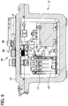
- FIG. 6 is a cross section of the control enclosure of FIG. 4 ;
- FIG. 7 is a cross section of another embodiment of a control enclosure including another embodiment of an operator mechanism mounted on a door of the control enclosure;
- FIG. 8 is a cross section of another embodiment of a control enclosure including another embodiment of an operator mechanism mounted on a door of the control enclosure;
- FIG. 9 is a cross section of another embodiment of a control enclosure including another embodiment of an operator mechanism mounted on a door of the control enclosure;
- FIG. 10 is a plan section of the control enclosure of FIG. 9 ;
- FIG. 11 is a cross section of another embodiment of a control enclosure including another embodiment of an operator mechanism mounted on a door of the control enclosure;
- FIG. 12 is a perspective of another embodiment of an operator mechanism constructed according to the teachings of the present disclosure.
- the operator mechanism disclosed herein provides offset position arrangements with respect to an actuator of a control device and continuous height adjustments so that the operator mechanism can be used with different control enclosures and/or with different control devices.
- an operator mechanism for a control enclosure is generally indicated at reference numeral 10 .
- the operator mechanism 10 is configured to be mounted on a control enclosure, such as the illustrated enclosure generally indicated at reference numeral 12 illustrated in FIGS. 4-8 .
- the control enclosure 12 may house electrical controls or other electrical devices, broadly, a control device generally indicated at 13 , for controlling and/or operating devices and systems.
- the control enclosure 12 can have various shapes and sizes depending upon the type of enclosure and the type and/or size of control devices houses therein.
- the control enclosure may be configured to house a motor controller, such as a motor starter.
- the control enclosure 12 may be a general purpose enclosure or an explosion proof enclosure.
- the enclosure 12 includes one or more walls defining an interior of the control enclosure, and in one embodiment, one of the walls is a door 14 , as shown in FIG. 4 , providing access to the interior of the control enclosure.
- the operator mechanism 10 may be mounted on the door 14 or other wall of the enclosure 12 .
- the illustrated operator mechanism 10 is configured as a push button operator mechanism. It is understood that the teachings set forth herein may be employed in other operator mechanism embodiments, including a pull button operator mechanism or a lever operator mechanism, for example.
- the operator mechanism 10 is offset or generally positioned to the side of the control device 13 that is operated by the operator mechanism. Moreover, the operator mechanism 10 is selectively adjustable to allow the operator mechanism to be used with different types of control enclosures and/or different types of control devices housed within the control enclosure.
- the illustrated operator mechanism 10 is configured as a push button operator mechanism. It is understood that the teachings set forth herein may be employed in other operator mechanism embodiments, including a pull button operator mechanism, for example.
- the push button operator mechanism 10 comprises a button assembly 16 having a cylindrical-shaped body 24 having a proximal end 26 and a distal end 28 .
- proximal distal
- distal distal
- a button 32 (broadly, a mechanical user interface) is positioned at the proximal end 26 of the button assembly 16 .
- the body 24 includes a button shroud 30 to protect the button 32 .
- a button shroud opening in the proximal end of the shroud 30 allows access to the button 32 .
- the button 32 is longitudinally movable or slidable within the body 24 between a proximal (i.e. initial or non-depressed position) and a distal (i.e. depressed) position.
- the button 32 is configured to be engaged by the user to depress or slide the button distally within the button shroud 30 of the body 24 .
- the button assembly 16 includes a spring (e.g. a compression spring), such as shown in the conventional operator mechanism of FIGS. 1A and 1B , that engages the body 24 to bias the button 32 in the proximal position.
- the button 32 is attached to a shaft attachment portion 33 that is positioned at the distal end 28 of the button assembly 16 .
- the shaft attachment portion 33 is configured to be longitudinally movable or slidable within the body 24 such that when the button 32 is moved by the user, the shaft attachment portion 33 moves as well. As explained in more detail below, the shaft attachment portion 33 is configured to couple to a shaft 20 of a contact assembly 18 . In other embodiments, the shaft 20 may be coupled to the button 32 in other ways, including being directly coupled thereto.
- the button assembly 16 may be of other designs and configurations.
- the button assembly 16 is configured to mount or secure the operator mechanism 10 on the door 14 or other wall of the control enclosure 12 .
- the body 24 includes an externally threaded section 34 configured to extend through an opening or hole in the door 14 such that the proximal end 26 of the button assembly 16 is positioned outside the interior and the distal end 28 of the button assembly is positioned inside the interior (i.e., the button 32 is positioned proximal of the door 14 or outside the interior of the enclosure 12 , accessible to the user).
- a face plate 36 is secured to the exterior of the body 24 , and a mount nut 38 is threaded onto the threaded section 34 of the body 24 .
- the face plate 36 is configured to seat against (e.g., engage) the exterior surface of the door 14 and the mount nut 38 is configured to seat against the interior surface of the door, as shown in FIGS. 6-8 , to secure the operator mechanism 10 to the enclosure 12 .
- Other methods of mounting the operator mechanism 10 to the control enclosure 12 are within the scope of the present invention.
- the operator mechanism 10 includes the contact assembly 18 that is coupled or secured to the button assembly 16 such that movement of the button 32 moves the contact assembly.
- the contact assembly includes a contact member 22 and the shaft 20 .
- the shaft 20 is fully threaded and has a proximal end 40 and a distal end 42 .
- the shaft 20 is coupled to and extends distally from the button assembly 16 .
- the proximal end 40 of the shaft 20 is coupled to the shaft attachment portion 33 of the button assembly 16 .
- the shaft 20 defines a threaded hole 41 at the proximal end 40 that is threaded onto the shaft attachment portion 33 .
- the shaft 20 of the contact assembly 18 extends through body 24 and is coupled directly to the button 32 , similar to the prior art in FIGS. 1A and 1B .
- the shaft 20 is longitudinally movable or slidable within the body 24 .
- Other ways of attaching the shaft 20 to the button assembly 16 are within the scope of the present disclosure, such as but not limited to making the shaft integral with the button assembly.
- the shaft 20 extends distally outward from the button assembly 16 to the distal end 42 .
- the shaft 20 has a length L between the proximal and distal ends 40 , 42 .
- the shaft 20 defines a longitudinal axis LA.
- the contact member 22 of the contact assembly 18 is coupled to the shaft 20 .
- the contact member 22 is configured to engage an actuator 15 of the control device 13 in the control enclosure when the contact assembly 18 is moved by the mechanical user interface (e.g., the button 32 ).
- the contact member 22 extends radially outward from the shaft 20 to engage the actuator 15 of the control device 13 .
- the contact member 22 comprises a contact plate 44 having a generally disc shape with an elliptical footprint, as can be seen in FIG. 5 .
- the contact plate 44 has a proximal face 48 and a distal face 50 .
- the contact plate 44 is generally flat with a height H extending parallel to the longitudinal axis LA and a radial extent E (generally, a width) transverse to the height, the height being less than the radial extent.
- the illustrated contact plate 44 has a circumference 46 (i.e., perimeter edge) greater than the circumference of the shaft 20 (i.e., the diameter of the contact plate is greater than the diameter of the shaft).
- the contact member 22 has an outer radial extent relative to the longitudinal axis LA greater than the outer radial extent of the shaft relative to the longitudinal axis.
- the outer radial extent of the contact plate 44 relative to the longitudinal axis LA is at least three times greater than the outer radial extent of the shaft relative to the longitudinal axis.
- the outer radial extent of the contact plate 44 may be from about three times to about twenty times greater than the outer radial extent of the shaft relative to the longitudinal axis, or at least about 5 times greater than the outer radial extent of the shaft relative to the longitudinal axis, or at least about 6 times greater than the outer radial extent of the shaft relative to the longitudinal axis, or at least 8 times greater than the outer radial extent of the shaft relative to the longitudinal axis, or at least 10 times greater than the outer radial extent of the shaft relative to the longitudinal axis.
- the contact plate 44 can have other footprint shapes such as, but not limited to, a square or rectangular footprint.
- the contact plate 44 can also be curved or bent out of plane to adapt the contact member 22 to a particular use or actuator of the control device 13 .
- the contact member 22 is selectively positionable longitudinally along the shaft 20 to adjust the longitudinal position of the contact member on the shaft.
- the contact member 22 defines a shaft opening 52 through which the shaft 20 extends.
- the distal end 42 of the shaft 20 is distal of the shaft opening 52 .
- the distal end 42 of the shaft 20 may be distal of the proximal and distal faces 48 , 50 of the contact plate 44 .
- the shaft opening 52 is positioned generally at the center of the contact plate 44 .
- the shaft opening 52 of the contact plate 44 is threaded such that the contact plate is threaded onto the shaft 20 (e.g., threadably mounted on the shaft).
- a nut 53 is threaded onto the shaft 20 and engages the distal face 50 of the contact plate 44 to inhibit the contact plate from moving longitudinally along the shaft.
- the contact plate 44 can be disposed between nuts threaded onto the shaft 20 that engage the contact plate on either side. In either embodiment, the contact plate 44 can be selectively positioned at any longitudinal position along the length of the shaft (e.g., continuous adjustment) to adjust the operator mechanism 10 to the particular control enclosure 12 and the control device 13 housed therein (i.e. the distance of the actuator 15 of the device from the door 14 as shown in FIGS. 6-8 ).
- the contact member 22 may have an adjustable footprint.
- the footprint of the contact member 22 can be adjustable to adapt the operator mechanism 10 to the particular control enclosure 12 and the particular position of the actuator 15 of the control device 13 therein.
- the operator mechanism can include various different contact plates 44 a , 44 b , 44 c , each having a different footprint. In this case, the user selects the contact plate 44 a , 44 b , 44 c with the particular footprint that suits a particular control enclosure 12 and control device.
- the operator mechanism can include a large footprint contact plate 44 c , a medium footprint contact plate 44 b , and a small footprint contact plate 44 a (i.e. different footprint sizes).
- each of these contact plates have a different diameter, such as the outer radial extent of each contact plate relative to the longitudinal axis LA varies.
- the diameter of the small footprint contact plate may be from about 1 inches (2.5 cm) to about 3 inches (7.6 cm)
- the diameter of the medium footprint contact plate may be from about 3 inches (7.6 cm) to about 5 inches (12.7 cm)
- the diameter of the large footprint contact plate may be from about 5 inches (12.7 cm) to about 8 inches (20.3 cm). Additional and/or different footprints are possible.
- the contact plates can have differently shaped footprints as well. Should the contact plate have an asymmetrical shape, the use of anti-rotation features with the shaft 20 or protruding from the enclosure may be used, as described below.
- the footprint of the contact member 22 is adjusted by removing portions thereof (not shown).
- the contact plate can have portions configured to be removed by the user to adjust the footprint of the contact plate.
- the contact plate can have score or perforation lines defining the portions which can be removed by the user.
- the contact member 22 defines a recess 54 sized and shaped to receive the distal end 28 of the button assembly 16 .
- the recess 54 allows the contact member 22 to engage the actuator 15 of the control device 13 , when the actuator is proximal of the distal end 28 of the button assembly 16 (i.e. the actuator is adjacent to the door 14 ).
- the contact member 22 comprises a contact plate 44 ′ and an adaptor 56 that connects the contact plate 44 ′ to the shaft 20 adjacent the distal end 28 of the button assembly 16 .
- the contact plate 44 ′ is similar to the contact plate 44 so that similar or analogous elements are labeled with the same reference numerals, with the addition of a trailing prime.
- the primary difference between contact plates 44 and 44 ′ is the shaft opening 52 ′ is larger than shaft opening 52 , to accommodate the adaptor 56 .
- the adaptor 56 radially offsets or radially spaces apart the contact plate 44 ′ from the shaft 20 (i.e., the edge defining the shaft opening 52 ′ has an inner radial extent relative to the longitudinal axis LA that is greater than the outer radial extent of the shaft relative to the longitudinal axis), allowing the distal end 28 of the button assembly 16 to extend through the shaft opening 52 ′ to be received in the recess 54 .
- the adaptor 56 includes a base 58 defining an adaptor shaft opening 64 .
- the adaptor shaft opening 64 is threaded onto the shaft 20 .
- the base 58 of the adaptor extends radially outward from the shaft 20 .
- a cylindrically shaped outer wall 60 extends perpendicularly from the base 58 to a radially outwardly facing lip 62 .
- the outer wall 60 defines the recess 54 .
- the interior surface of the outer wall 60 is radially spaced apart from the shaft 20 a sufficient distance such that the distal end 28 of the button assembly 16 can be received in the recess 54 .
- the interior surface of the outer wall 60 has an inner radial extent relative to the longitudinal axis LA that is greater than an outer radial extent of the distal end 28 of the button assembly 16 relative to the longitudinal axis).
- the exterior surface of the outer wall 60 is threaded and configured to extend through the shaft opening 52 ′ of the contact plate 44 ′.
- a mount nut 66 is threaded onto the outer wall 60 .
- the mount nut 66 is configured to seat against the distal face 50 ′ of the contact plate 44 ′ and the lip 62 is configured to seat against the proximal face 48 ′ of the contact plate 44 to secure the contact plate to the adaptor 56 .
- the adaptor 56 can be selectively positioned at any longitudinal position long the shaft 20 .
- the adaptor 56 and contact plate 44 ′ are turned upside-down (from the orientation shown in FIG. 11 ) and the adaptor coupled adjacent to the distal end 42 of the shaft 20 to position the contact plate 44 ′ distal of the shaft.
- the adaptor 56 and contact plate 44 ′ can be formed in one-piece construction (i.e. a single component, not two separate components) such that the contact plate itself defines the recess 54 .
- Each of the components of the operator mechanism 10 can be formed from any suitable material, including, but not limited to, metal and plastic. In one example, all of the components may be made from metal. The components may be formed from other suitable materials.
- the operator mechanism 10 is attached to the door 14 of the panel enclosure 12 such that a proximal end of the operator mechanism is outside the interior of the enclosure and a distal end of the operator mechanism is inside the interior of the enclosure.
- the body 24 of the button assembly 16 extends through an opening in the door 14 (e.g., the wall) of the control enclosure 12 .
- the face plate 36 engages the exterior surface of the door 14 and the mount nut 38 is tightened against the interior surface of the door, to mount the operator mechanism 10 on the door.
- the longitudinal position of the contact member 22 is adjusted to account for the location (e.g., height) of the actuator 15 of the device 13 in the control enclosure 12 .
- the contact member 22 is longitudinally adjusted on the shaft 20 such that the contact member will engage or contact the actuator 15 when the contact assembly 18 is moved distally as the button 32 is depressed.
- the contact member 22 is positioned near the middle of the shaft 20 to engage the actuator 15 ( FIG. 6 ).
- the contact plate 44 and/or nut(s) 53 are threaded (rotated) on the shaft 20 to move the contact member into the desired position.
- the opening in the door is not aligned with the actuator 15 of the control device 13 such that the actuator is radially spaced apart (e.g., offset) from the longitudinal axis LA of the shaft 20 .
- the contact member 22 extends radially outward from the shaft 20 such that the contact member overlies at least a portion of the actuator 15 .
- the actuator 15 of the device 13 has an inner radial extent relative to the longitudinal axis LA that is less than the outer radial extent of the contact member 22 relative to the longitudinal axis.
- the contact member 22 completely overlies the actuator ( FIG. 6 ).
- the operator mechanism 10 is able to engage an actuator 15 that is laterally or radially offset from the shaft of the operator mechanism and is adjacent to the door 14 , adjacent to the floor (i.e. the wall of the enclosure 12 opposite the door), or anywhere in-between from a single position (i.e. hole) in the door.
- the shaft 20 of the operator mechanism 10 can rotate relative to the button assembly 16 .
- the contact member 22 has a circular footprint so that regardless of any shaft 20 rotation, a portion of the contact member 22 will always overlie and be able to engage the actuator 15 of the control device 13 .
- the operator mechanism 10 includes an anti-rotation mechanism or other ways to inhibit rotation of the shaft 20 relative to the button assembly 16 .
- the anti-rotation feature ensures the contact member will stay in an overlapping arrangement with the actuator 15 .
- the contact member 22 can have other footprints, as described above. Further details on suitable anti-rotation features are described in U.S. Patent Publication No. 2018/0232004, the entirety of which is hereby incorporated by reference.
- FIGS. 7 and 8 additional embodiments of an operator mechanism are generally indicated at reference numerals 110 and 210 , respectively.
- the operator mechanisms 110 , 210 are similar to operator mechanism 10 , described above, except the operator mechanisms 110 , 210 are mounted to control enclosures 112 and 212 , respectively.
- Control enclosures 12 , 112 and 212 have different sizes and different control devices such that the actuator 15 , 115 , 215 of each control device 13 , 113 , 213 is in a different position relative to the operator mechanism 10 , 110 , 210 , respectively.
- the contact member 22 of each operator mechanisms 110 , 210 have different positions on the shaft 20 (relative to each other and operator mechanism 10 ) in order to engage the actuator 115 , 215 in each control enclosure 112 , 212 , respectively.
- the contact member 22 of the operator mechanism 110 is positioned on the shaft 20 near the distal end 42 .
- the contact member 22 of the operator mechanism 210 is positioned on the shaft 20 near the proximal end 40 .
- operator mechanisms 110 , 210 have button assemblies 116 , 216 with longer bodies 124 , 224 to extend through the thicker doors 114 and 214 of control enclosures 112 , 212 , respectively.
- Operator mechanisms 110 , 210 can also have a different shaft and a different contact member than operator mechanism 10 .
- Operator mechanism 310 is similar to operator mechanism 10 , described above, except operator mechanism 310 has a large footprint contact plate 44 c ( FIG. 10 ).
- the operator mechanism 310 is mounted on the door 314 of the control enclosure 312 and is configured to engage the actuator 315 of the control device 313 .
- the actuator is a lever-type actuator and the contact plate 44 c overlies a portion of the actuator.
- the operator mechanism 10 with the adaptor 56 is mounted on the door 14 of the control enclosure 12 .
- the actuator 15 of the control device 13 is positioned adjacent to the interior surface of the door 14 such that the actuator is proximal of the distal end 28 of the button assembly 16 .
- the adaptor 56 is attached to the shaft 20 adjacent the distal end 28 of the button assembly 16 such that the distal end is partially received in the recess 54 .
- the adaptor positions the contact plate 44 ′ proximal of the actuator 15 such that the contact plate will engage the actuator when moved in the distal direction.
- the operator mechanism 10 ability to engage an actuator 15 that is radially spaced apart from the shaft 20 , the operator mechanism and actuator do not need to be longitudinally aligned (i.e. the shaft 20 does not need to be aligned with the actuator).
- the shaft 20 of the operator mechanism 10 is no longer limited in length by the control device because the shaft can be offset or placed to the side of the device.
- This allows a standard length shaft to be used for a wide variety of different control devices without having to vary or adjust the length of the shaft or an extender thereon (prior art, FIGS. 1A and 1B ).
- This also allows the depth of the enclosure to be reduced because of the ability to engage an actuator located adjacent the door (i.e. space above the actuator for the entire operator mechanism is no longer required).
- the ability to adjust the position of the contact member 22 on the shaft 20 allows the operator mechanism 10 to be used with a numerous different control enclosures and control devices.
- the operator mechanism may be of other types, besides a push button operator mechanism, that incorporate the teachings set forth herein for the offset arrangement of the operator mechanism.
- the operator mechanisms can be a pull button operator mechanism that is moved by the user in the proximal direction to engage an actuator of a control device.
Landscapes
- Physics & Mathematics (AREA)
- General Physics & Mathematics (AREA)
- Engineering & Computer Science (AREA)
- Automation & Control Theory (AREA)
- Power-Operated Mechanisms For Wings (AREA)
- Accommodation For Nursing Or Treatment Tables (AREA)
- Endoscopes (AREA)
- Mechanical Control Devices (AREA)
Abstract
Description
Claims (13)
Priority Applications (1)
| Application Number | Priority Date | Filing Date | Title |
|---|---|---|---|
| US16/283,063 US10817009B2 (en) | 2018-02-23 | 2019-02-22 | Offset operator mechanism for control enclosure |
Applications Claiming Priority (2)
| Application Number | Priority Date | Filing Date | Title |
|---|---|---|---|
| US201862634486P | 2018-02-23 | 2018-02-23 | |
| US16/283,063 US10817009B2 (en) | 2018-02-23 | 2019-02-22 | Offset operator mechanism for control enclosure |
Publications (2)
| Publication Number | Publication Date |
|---|---|
| US20190265745A1 US20190265745A1 (en) | 2019-08-29 |
| US10817009B2 true US10817009B2 (en) | 2020-10-27 |
Family
ID=67683020
Family Applications (1)
| Application Number | Title | Priority Date | Filing Date |
|---|---|---|---|
| US16/283,063 Active US10817009B2 (en) | 2018-02-23 | 2019-02-22 | Offset operator mechanism for control enclosure |
Country Status (3)
| Country | Link |
|---|---|
| US (1) | US10817009B2 (en) |
| CA (1) | CA3034462A1 (en) |
| MX (1) | MX391721B (en) |
Families Citing this family (1)
| Publication number | Priority date | Publication date | Assignee | Title |
|---|---|---|---|---|
| MX2019009474A (en) * | 2017-02-10 | 2019-09-16 | Eaton Intelligent Power Ltd | Operator mechanism for control enclosure. |
Citations (3)
| Publication number | Priority date | Publication date | Assignee | Title |
|---|---|---|---|---|
| US3392593A (en) * | 1966-04-25 | 1968-07-16 | Square D Co | Manual reset mechanism for overload relays |
| US10263400B2 (en) * | 2016-09-08 | 2019-04-16 | Hubbell Incorporated | Actuator assembly for electrical switches housed in an enclosure |
| US10310542B2 (en) * | 2017-02-10 | 2019-06-04 | Eaton Intelligent Power Limited | Operator mechanism for control enclosure |
-
2019
- 2019-02-21 CA CA3034462A patent/CA3034462A1/en active Pending
- 2019-02-22 MX MX2019002164A patent/MX391721B/en unknown
- 2019-02-22 US US16/283,063 patent/US10817009B2/en active Active
Patent Citations (3)
| Publication number | Priority date | Publication date | Assignee | Title |
|---|---|---|---|---|
| US3392593A (en) * | 1966-04-25 | 1968-07-16 | Square D Co | Manual reset mechanism for overload relays |
| US10263400B2 (en) * | 2016-09-08 | 2019-04-16 | Hubbell Incorporated | Actuator assembly for electrical switches housed in an enclosure |
| US10310542B2 (en) * | 2017-02-10 | 2019-06-04 | Eaton Intelligent Power Limited | Operator mechanism for control enclosure |
Also Published As
| Publication number | Publication date |
|---|---|
| MX2019002164A (en) | 2019-08-26 |
| CA3034462A1 (en) | 2019-08-23 |
| MX391721B (en) | 2025-03-21 |
| US20190265745A1 (en) | 2019-08-29 |
Similar Documents
| Publication | Publication Date | Title |
|---|---|---|
| US9543093B2 (en) | Universal box system | |
| US20180115142A1 (en) | Modular push switch mechanism | |
| EP1879093A2 (en) | Improved knob assembly for operating the switch of a radio | |
| US8094851B2 (en) | Hearing apparatus having a rocker-like actuator for switching on/off | |
| US10817009B2 (en) | Offset operator mechanism for control enclosure | |
| EP3204577A1 (en) | Door mount mechanism for a smart lock system | |
| US5243157A (en) | Lockable handle | |
| US6504460B2 (en) | Actuator mechanism for an external circuit breaker operating device | |
| US7161100B1 (en) | Limit switch mechanism for door opening | |
| US5967301A (en) | Popout control assembly for radios | |
| CN100449664C (en) | Switches with multi-directional heads | |
| EP0526409A1 (en) | Washer for spring latch lock handles, including a return spring | |
| US5225970A (en) | Twist-in mounting for electromechanical component | |
| US4733416A (en) | Push-button operating mechanism for a water closet | |
| JP2003337628A (en) | Rotation range regulatory mechanism and electric equipment using the same | |
| US6949711B1 (en) | Selector switch knob with lock ring assembly | |
| US6328357B1 (en) | Trim actuator for use with an exit device | |
| US20190198268A1 (en) | Holding adapter for fixing control and signaling devices and also arrangement | |
| US20110308921A1 (en) | Contact block with interlock | |
| US7339125B2 (en) | Safety switch operating mechanism | |
| US10656668B2 (en) | Operator mechanism for control enclosure | |
| RU2475880C2 (en) | Housing with structural assembly positioned therein | |
| US10695894B2 (en) | Ratchet handle | |
| US5906126A (en) | Angle adjusting device of steel bar bending apparatus | |
| US9018555B2 (en) | Security cover plate for light switch |
Legal Events
| Date | Code | Title | Description |
|---|---|---|---|
| AS | Assignment |
Owner name: EATON INTELLIGENT POWER LIMITED, IRELAND Free format text: ASSIGNMENT OF ASSIGNORS INTEREST;ASSIGNORS:DECARR, GRAIG EDMUND;LEDGERWOOD, ADAM;REEL/FRAME:048412/0832 Effective date: 20180530 |
|
| FEPP | Fee payment procedure |
Free format text: ENTITY STATUS SET TO UNDISCOUNTED (ORIGINAL EVENT CODE: BIG.); ENTITY STATUS OF PATENT OWNER: LARGE ENTITY |
|
| STPP | Information on status: patent application and granting procedure in general |
Free format text: NON FINAL ACTION MAILED |
|
| STPP | Information on status: patent application and granting procedure in general |
Free format text: RESPONSE TO NON-FINAL OFFICE ACTION ENTERED AND FORWARDED TO EXAMINER |
|
| STPP | Information on status: patent application and granting procedure in general |
Free format text: ADVISORY ACTION MAILED |
|
| STPP | Information on status: patent application and granting procedure in general |
Free format text: NOTICE OF ALLOWANCE MAILED -- APPLICATION RECEIVED IN OFFICE OF PUBLICATIONS |
|
| STCF | Information on status: patent grant |
Free format text: PATENTED CASE |
|
| MAFP | Maintenance fee payment |
Free format text: PAYMENT OF MAINTENANCE FEE, 4TH YEAR, LARGE ENTITY (ORIGINAL EVENT CODE: M1551); ENTITY STATUS OF PATENT OWNER: LARGE ENTITY Year of fee payment: 4 |