US10816074B2 - Actuator mechanism - Google Patents
Actuator mechanism Download PDFInfo
- Publication number
- US10816074B2 US10816074B2 US15/048,241 US201615048241A US10816074B2 US 10816074 B2 US10816074 B2 US 10816074B2 US 201615048241 A US201615048241 A US 201615048241A US 10816074 B2 US10816074 B2 US 10816074B2
- Authority
- US
- United States
- Prior art keywords
- actuator
- pin
- actuator pin
- lock
- detent
- Prior art date
- Legal status (The legal status is an assumption and is not a legal conclusion. Google has not performed a legal analysis and makes no representation as to the accuracy of the status listed.)
- Active
Links
Images


Classifications
-
- F—MECHANICAL ENGINEERING; LIGHTING; HEATING; WEAPONS; BLASTING
- F16—ENGINEERING ELEMENTS AND UNITS; GENERAL MEASURES FOR PRODUCING AND MAINTAINING EFFECTIVE FUNCTIONING OF MACHINES OR INSTALLATIONS; THERMAL INSULATION IN GENERAL
- F16H—GEARING
- F16H53/00—Cams or cam-followers, e.g. rollers for gearing mechanisms
- F16H53/02—Single-track cams for single-revolution cycles; Camshafts with such cams
-
- F—MECHANICAL ENGINEERING; LIGHTING; HEATING; WEAPONS; BLASTING
- F15—FLUID-PRESSURE ACTUATORS; HYDRAULICS OR PNEUMATICS IN GENERAL
- F15B—SYSTEMS ACTING BY MEANS OF FLUIDS IN GENERAL; FLUID-PRESSURE ACTUATORS, e.g. SERVOMOTORS; DETAILS OF FLUID-PRESSURE SYSTEMS, NOT OTHERWISE PROVIDED FOR
- F15B15/00—Fluid-actuated devices for displacing a member from one position to another; Gearing associated therewith
- F15B15/20—Other details, e.g. assembly with regulating devices
- F15B15/26—Locking mechanisms
- F15B15/261—Locking mechanisms using positive interengagement, e.g. balls and grooves, for locking in the end positions
-
- B—PERFORMING OPERATIONS; TRANSPORTING
- B64—AIRCRAFT; AVIATION; COSMONAUTICS
- B64D—EQUIPMENT FOR FITTING IN OR TO AIRCRAFT; FLIGHT SUITS; PARACHUTES; ARRANGEMENT OR MOUNTING OF POWER PLANTS OR PROPULSION TRANSMISSIONS IN AIRCRAFT
- B64D29/00—Power-plant nacelles, fairings or cowlings
- B64D29/06—Attaching of nacelles, fairings or cowlings
-
- E—FIXED CONSTRUCTIONS
- E05—LOCKS; KEYS; WINDOW OR DOOR FITTINGS; SAFES
- E05F—DEVICES FOR MOVING WINGS INTO OPEN OR CLOSED POSITION; CHECKS FOR WINGS; WING FITTINGS NOT OTHERWISE PROVIDED FOR, CONCERNED WITH THE FUNCTIONING OF THE WING
- E05F15/00—Power-operated mechanisms for wings
- E05F15/50—Power-operated mechanisms for wings using fluid-pressure actuators
- E05F15/53—Power-operated mechanisms for wings using fluid-pressure actuators for swinging wings
-
- E—FIXED CONSTRUCTIONS
- E05—LOCKS; KEYS; WINDOW OR DOOR FITTINGS; SAFES
- E05F—DEVICES FOR MOVING WINGS INTO OPEN OR CLOSED POSITION; CHECKS FOR WINGS; WING FITTINGS NOT OTHERWISE PROVIDED FOR, CONCERNED WITH THE FUNCTIONING OF THE WING
- E05F15/00—Power-operated mechanisms for wings
- E05F15/60—Power-operated mechanisms for wings using electrical actuators
- E05F15/603—Power-operated mechanisms for wings using electrical actuators using rotary electromotors
- E05F15/611—Power-operated mechanisms for wings using electrical actuators using rotary electromotors for swinging wings
-
- E—FIXED CONSTRUCTIONS
- E05—LOCKS; KEYS; WINDOW OR DOOR FITTINGS; SAFES
- E05Y—INDEXING SCHEME ASSOCIATED WITH SUBCLASSES E05D AND E05F, RELATING TO CONSTRUCTION ELEMENTS, ELECTRIC CONTROL, POWER SUPPLY, POWER SIGNAL OR TRANSMISSION, USER INTERFACES, MOUNTING OR COUPLING, DETAILS, ACCESSORIES, AUXILIARY OPERATIONS NOT OTHERWISE PROVIDED FOR, APPLICATION THEREOF
- E05Y2201/00—Constructional elements; Accessories therefor
- E05Y2201/40—Motors; Magnets; Springs; Weights; Accessories therefor
- E05Y2201/404—Function thereof
- E05Y2201/42—Function thereof for locking
-
- E—FIXED CONSTRUCTIONS
- E05—LOCKS; KEYS; WINDOW OR DOOR FITTINGS; SAFES
- E05Y—INDEXING SCHEME ASSOCIATED WITH SUBCLASSES E05D AND E05F, RELATING TO CONSTRUCTION ELEMENTS, ELECTRIC CONTROL, POWER SUPPLY, POWER SIGNAL OR TRANSMISSION, USER INTERFACES, MOUNTING OR COUPLING, DETAILS, ACCESSORIES, AUXILIARY OPERATIONS NOT OTHERWISE PROVIDED FOR, APPLICATION THEREOF
- E05Y2201/00—Constructional elements; Accessories therefor
- E05Y2201/60—Suspension or transmission members; Accessories therefor
- E05Y2201/622—Suspension or transmission members elements
- E05Y2201/638—Cams; Ramps
-
- E—FIXED CONSTRUCTIONS
- E05—LOCKS; KEYS; WINDOW OR DOOR FITTINGS; SAFES
- E05Y—INDEXING SCHEME ASSOCIATED WITH SUBCLASSES E05D AND E05F, RELATING TO CONSTRUCTION ELEMENTS, ELECTRIC CONTROL, POWER SUPPLY, POWER SIGNAL OR TRANSMISSION, USER INTERFACES, MOUNTING OR COUPLING, DETAILS, ACCESSORIES, AUXILIARY OPERATIONS NOT OTHERWISE PROVIDED FOR, APPLICATION THEREOF
- E05Y2800/00—Details, accessories and auxiliary operations not otherwise provided for
- E05Y2800/74—Specific positions
- E05Y2800/742—Specific positions abnormal
- E05Y2800/744—Specific positions abnormal cleaning or service
-
- E—FIXED CONSTRUCTIONS
- E05—LOCKS; KEYS; WINDOW OR DOOR FITTINGS; SAFES
- E05Y—INDEXING SCHEME ASSOCIATED WITH SUBCLASSES E05D AND E05F, RELATING TO CONSTRUCTION ELEMENTS, ELECTRIC CONTROL, POWER SUPPLY, POWER SIGNAL OR TRANSMISSION, USER INTERFACES, MOUNTING OR COUPLING, DETAILS, ACCESSORIES, AUXILIARY OPERATIONS NOT OTHERWISE PROVIDED FOR, APPLICATION THEREOF
- E05Y2900/00—Application of doors, windows, wings or fittings thereof
- E05Y2900/50—Application of doors, windows, wings or fittings thereof for vehicles
- E05Y2900/502—Application of doors, windows, wings or fittings thereof for vehicles for aircraft or spacecraft
Definitions
- the present invention relates to an actuator mechanism moveable between a locked and an unlocked position.
- the mechanism is particularly, but not exclusively, for use in aircraft engines, and finds particular application in opening and closing aircraft engine cowls.
- Aircraft engine cowls such as those covering the C-duct and fans need to be opened occasionally to allow access to the engine for e.g. repair and maintenance, and then closed again.
- Actuators are provided to open and close the cowls. Preferably no pressure or driving force should be required to keep the actuator in the open position, despite the weight of the cowl door.
- the actuators generally comprise an extendible rod or arm that is attached to open the cowl as it extends and close the cowl as it retracts under the weight of the cowl door.
- a typical hydraulic actuator comprises a piston rod, a cylinder and a rotatable lock mechanism to facilitate mechanical operation of the cowl door or flap. Pressure is applied to fully extend the actuator; when fully extended, pressure is removed allowing the actuator to retract by a small amount which causes the actuator to lock, as the lock mechanism rotates and engages the activator. To close, or stow, the cowl door, the actuator is then extended by application of pressure out of the locked position to its fully extended position from which, as pressure is removed, the actuator is able to return to a retracted, stowed, position.
- a rotatable lock mechanism in cooperation with a lock pin, provides the paths for the actuator to take up its locked position or return to its stowed position, as will be described further below.
- EP 2532821 describes an improved actuator mechanism that avoids the actuator stopping in such an intermediate position.
- EP 2532821 provides a resilient detent in the paths for a locking pin provided by the lock mechanism such that once the locking pin has moved beyond a predetermined position in the extending direction the resilient detent prevents return movement of the pin along the entry path.
- a further problem has been identified with the known actuator mechanism when the actuator is used to return the cowl to the stowed state.
- the actuator is extended (out of the locked state) and then, due to the paths defined by the lock mechanism, returns to the retracted state, via an exit path.
- the pin can again become stuck in position at an intermediate point, rather than automatically feed into and follow the exit path under the weight of the cowl. This intermediate position can be falsely interpreted as a locked state. If the actuator is jolted or slightly disturbed, the locking pin can slip from the intermediate point, back into the locked position, which can damage the door as well as damage other parts or cause injury.
- a spring biased detent ball retainer ensures that before the actuator locks onto such an intermediate point, the detent ball which is timed to run over a cam-like profile, rotates the collar lock so that the lock pin either moves into the locked state or the unlocked state.
- Torque generated by the spring biased detent ball shall always be greater than the varying resistive torque.
- the torque generated is highly sensitive to the cam like profile the detent ball traces.
- the resistive torque depends upon factors such as thickness of the thin fluid film between the piston and lock collar (clearance), viscous drag on surfaces of rotating components, viscosity of working fluid which is, in turn, a function of ambient temperature.
- the present invention therefore aims to provide an actuator locking mechanism that can prevent the actuator becoming stuck in an intermediate position when intended to be moved from the locked position to the stowed position, without reliance on a spring biased detent ball.
- the present invention in one aspect, provides an actuator system comprising a rotatable lock mechanism defining a path for an actuator pin as the actuator is expanded and retracted, wherein the lock mechanism defines an entry passage through which the pin enters as the actuator extends, a guide surface along which the pin travels from the entry passage as the actuator retracts, a locking recess into which the pin is guided by the guide surface, and an exit passage into which the pin is guided as it is caused to leave the lock recess by extension of the actuator and subsequent retraction; whereby a detent surface is provided to prevent the pin returning back into the lock recess when the actuator is extended to cause the pin to leave the lock recess.
- the invention provides an actuator system comprising a rotatable lock mechanism defining a path for an actuator pin as the actuator is expanded and retracted, wherein the lock mechanism defines an entry passage through which the pin enters as the actuator extends, a guide surface along which the pin travels from the entry passage as the actuator retracts, a locking recess into which the pin is guided by the guide surface, and an exit passage into which the pin is guided as it is caused to leave the lock recess by extension of the actuator and subsequent retraction; whereby the lock mechanism provides a sloping engagement surface for the pin either side of the entry passage.
- the lock mechanism of the second aspect may provide advantages alone or in combination with the detent of the first aspect.
- FIG. 1 shows an actuator according to an embodiment of the invention, in use.
- FIG. 2 shows a perspective view of an actuator according to the invention.
- FIG. 3 is a cut-away view of one end of the actuator of FIG. 2 , with the cylinder removed to aid description.
- FIG. 4A shows the locking mechanism at the start of the locking procedure.
- FIG. 4B shows the detent ball mechanism in cross section at the point shown in FIG. 4A .
- FIGS. 5A to 17B show how the various components move relative to each other during the locking and unlocking procedure.
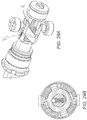
- FIG. 18A shows an improved locking mechanism according to another aspect of the invention.
- FIG. 18B is an exploded view of the locking mechanism of FIG. 18A .
- FIGS. 19A to 31B show how the various components move relative to each other during the locking and unlocking procedure.
- FIG. 1 shows an actuator according to an embodiment of the invention, in use.
- FIG. 1 shows part of an engine housing 10 including a door 12 moveable between a closed, in use position, and an open position.
- the door 12 is shown in its open position.
- An actuator 14 is arranged to drive the door ( 12 ) between the two positions.
- the actuator is in the form of a hydraulic piston or ram comprising a housing cylinder ( 16 ) within which a piston ( 20 ) is slidable.
- the cylinder is mounted to the engine housing 10 , by means of an eye end (shown in FIG. 2 ), while the door is connected to an end of the piston rod ( 22 ), again via an eye end.
- actuator By controlling the pressure of fluid ( 24 ) applied to a chamber ( 18 ) within the actuator, extension and retraction of the actuator can be controlled so as to drive the door between its closed and opened positions.
- Other types of actuators may be used, including electrically or mechanically driven actuators.
- the actuator comprises an eye ( 50 a , 50 b ) at each end for attachment, respectively, to the engine and to the door to be opened and closed.
- a cylinder ( 51 ) runs between the ends within which an piston rod ( 52 ) is axially slidably mounted.
- a port ( 53 ) is provided through the cylinder close to one end, through which fluid can be provided to hydraulically move the piston rod within/along the cylinder.
- a rotating lock mechanism ( 54 ) is provided at an end of the piston (the end closest to the port when the piston is retracted within the cylinder). The lock mechanism is fixed to move axially with the piston rod and is rotatable within the cylinder.
- One or more locking pins ( 55 ) are mounted on and extend through the cylinder wall at a location between the fluid port and the opposite end of the cylinder. As pressure is applied to the piston rod via the fluid port, the rod, together with the lock mechanism, moves axially away from the port, extending the actuator rod and moving the lock mechanism towards the pin(s).
- the lock mechanism defines a path for the locking pin(s) including an entry passage, a locking recess, and an exit passage.
- the lock mechanism comprises a collar lock 60 comprising a collar having the path defined in its outer surface and, preferably, grooves in e.g. a helical formation on its inner surface.
- a spring biased detent ball arrangement ( 56 ) is biased across the inner bore of the collar such that a spring biases balls to run in and out of the grooves in the inner surface.
- the lock mechanism also comprises guide surfaces to direct the pins along appropriate paths, and detent means, as described above. These may be provided on one or more gates or rings 62 that cooperate with the collar, or may be formed as part of the collar itself.
- the lock mechanism engages the pin(s) in the cylinder, such that a pin enters an entry passage 60 of the collar lock ( FIGS. 4A, 4B ).
- the pin moves into the entry passage ( FIGS. 5A, 5B ) riding over a resilient detent finger 100 and pressing it down. After a certain degree of extension, the pin has reached the end of the entry passage and passes over the detent finger 100 which springs back to its raised position so that the pin cannot return along the entry passage ( FIGS. 6A, 6B ).
- the actuator is extended further, to its fully extended position. Pressure is then removed from the piston rod ( FIGS. 7A, 7B ).
- Resilient detent means are provided in the passages. As the pin runs over these, it presses them down. Once the pin has passed over the detent means, in some embodiments, the detent means springs pack up preventing return of the pin and also preferably providing a sloped guide surface.
- the spring biased detent ball 200 also helps to drive the actuator into an end state (locked or stowed) rather than hanging at an intermediate point ( FIG. 14B ).
- the reliability and extent of support from the detent ball is, however, very limited, as mentioned above.
- FIG. 18A shows a partial perspective view of an actuator according to the invention.
- FIG. 18B is an exploded view of the locking mechanism.
- the invention provides a resilient detent 120 at the exit of the passage leading to the lock recess. This detent deflects down as the pin rides over it as the actuator extends to release the lock and, due to its resilience, springs up to form a detent once the pin has passed over it. Thus, even if the actuator is not fully extended, the pin is prevented from returning to the lock recess.
- the detent is preferably also formed with a sloping surface or ramp 130 such that as the pin passes over the detent, and pressure is removed, the pin rides along this ramp to cause rotation of the collar lock and guide the pin into the exit passageway 140 from which it exits the lock collar to retract the actuator.
- the pins enter the entry passage 150 as the actuator is extended ( FIG. 20A ). As the actuator continues to extend, the pin passes over the resilient detent 120 at the end of the entry passage. As the pin passes over the detent, it presses it down. The detent returns to its raised position after the pin has cleared it, preventing the pin returning back down the entry passage.
- the actuator is then fully extended ( FIG. 27 ) after which pressure is removed.
- the actuator then begins to retract under the weight of the attached door.
- the pin abuts another sloping surface 180 ( FIG. 28 ) which may be formed, or partially formed, by the detent, causing the collar to rotate.
- the pin is guided around the collar and into an exit passage 190 ( FIG. 29 ) below the raised part of a detent.
- the exit passage is preferably the same passage as the initial entry passage.
- the pin then exits the collar through the exit passage to fully retract the actuator and stow the door.
- the spring biased detent ball 200 ′ mechanism in existing systems helps, to some extent, to prevent the locking pin(s) hanging at a null point and appearing to be in a locked position when the actuator is not, in fact, locked.
- the spring biased detent ball mechanism can be seen in FIGS. 19B to 31B and comprises a spring 56 ′ which biases two balls 200 ′ at its ends against the inner wall of the lock collar.
- This inner wall is provided with a profile within which the balls travel as the collar is caused to rotate by the locking pins engaging with the lock collar outer path and passageways.
- the spring biased detent ball mechanism provides an alignment mechanism in the event that the two eye ends (see FIG. 2 ) have been displaced, angularly, with respect to each other. If this happens, the locking pin will not directly meet the entry passage of the locking collar as the actuator is extended, but will engage with the locking collar slightly to the side of the entrance passage. Provided the angular displacement between the two eye ends is fairly small (not more than around 5 or 6 degrees), the spring biased detent ball will operate to rotate the collar such that the pin is aligned with the entry passage. This works because, as can be seen in FIG. 14B , the torque generated by the detent ball in the groove provided inside the locking collar will quickly index the collar lock back to its locked state.
- Another feature of an aspect of the present invention provides a solution to this problem and ensures, to a much greater degree, that even with larger angular deviations between the eye ends, up to around 45 degrees, the locking mechanism never hangs at a null point.
- the solution to this problem is to provide a helical or sloping profile on the surface of the locking collar that comes into engagement with the locking pin(s).
- the pin and sloping surface interact to cause rotation of the locking collar relative to the pin until the pin reaches the entry passage and the actuator locking mechanism then operates in a way similar to that described above.
- This aspect of the invention provides a greatly increased tolerance to angular misalignment between the eye ends, without relying on the spring biased detent ball mechanism.
- the spring biased detent ball will still be provided to orient the helix profile on the mechanism of the locking collar with respect to the lock pin and retains the locking collar from rotating beyond a certain angle due to vibration, when the actuator is at the stowed state.
- This modification will ensure that the pin(s) does not ever meet the locking collar at the flat land (which, in comparison to the prior systems, is small) when extended, but the ball mechanism cannot, as it can in the prior systems, cause a safety issue by falsely indicating that the actuator is locked, due to the ball being positioned at a null point.
- this outer sloped or helical profile is provided in combination with the spring-biased detent mechanism provided at the end of the locking passage, to avoid false locking or positioning. It is envisaged, however, that advantages could be provided by the sloped profile per se.
Landscapes
- Engineering & Computer Science (AREA)
- General Engineering & Computer Science (AREA)
- Mechanical Engineering (AREA)
- Physics & Mathematics (AREA)
- Fluid Mechanics (AREA)
- Aviation & Aerospace Engineering (AREA)
- Lock And Its Accessories (AREA)
- Actuator (AREA)
Abstract
Description
Claims (3)
Applications Claiming Priority (3)
| Application Number | Priority Date | Filing Date | Title |
|---|---|---|---|
| EP15155762.6A EP3059369B1 (en) | 2015-02-19 | 2015-02-19 | Actuator mechanism |
| EP15155762 | 2015-02-19 | ||
| EP15155762.6 | 2015-02-19 |
Publications (2)
| Publication Number | Publication Date |
|---|---|
| US20160245387A1 US20160245387A1 (en) | 2016-08-25 |
| US10816074B2 true US10816074B2 (en) | 2020-10-27 |
Family
ID=52484381
Family Applications (1)
| Application Number | Title | Priority Date | Filing Date |
|---|---|---|---|
| US15/048,241 Active US10816074B2 (en) | 2015-02-19 | 2016-02-19 | Actuator mechanism |
Country Status (2)
| Country | Link |
|---|---|
| US (1) | US10816074B2 (en) |
| EP (1) | EP3059369B1 (en) |
Families Citing this family (3)
| Publication number | Priority date | Publication date | Assignee | Title |
|---|---|---|---|---|
| US10472874B2 (en) * | 2014-12-22 | 2019-11-12 | Bonnie BERGERON | Automatic pneumatically-actuated gate and latch |
| EP3244071B1 (en) * | 2016-05-06 | 2019-04-17 | Goodrich Aerospace Services Pvt Ltd | Actuator mechanism |
| US11078708B2 (en) * | 2017-11-13 | 2021-08-03 | Hamilton Sunstrand Corporation | Hydraulic piston actuator for a door |
Citations (12)
| Publication number | Priority date | Publication date | Assignee | Title |
|---|---|---|---|---|
| US2923206A (en) * | 1955-05-11 | 1960-02-02 | Melin Tool Company Inc | Indexing attachment for milling machines and the like |
| US3799036A (en) * | 1972-07-17 | 1974-03-26 | R Slaughter | Self-locking fluid operated cylinder |
| FR2666111A1 (en) | 1990-08-24 | 1992-02-28 | Renault | FLAP OPENING AND CLOSING DEVICE. |
| US5222277A (en) * | 1992-03-31 | 1993-06-29 | Aec-Able Engineering Co., Inc. | Intermittently and reversibly operable hot wax energized hinge |
| US7540207B2 (en) * | 2002-01-24 | 2009-06-02 | Wittenstein Ag | Device for actuating the doors of vehicles |
| US20090139141A1 (en) * | 2007-11-30 | 2009-06-04 | Macleod Michael Fergus | Automatic door opener |
| US7975584B2 (en) * | 2007-02-21 | 2011-07-12 | Curt G. Joa, Inc. | Single transfer insert placement method and apparatus |
| US20110197391A1 (en) * | 2010-02-12 | 2011-08-18 | Rick Yu | Automatic door closer structure |
| US8272285B2 (en) * | 2008-04-03 | 2012-09-25 | Goodrich Actuation Systems Limited | Failsafe actuator |
| EP2532821A2 (en) | 2011-06-07 | 2012-12-12 | Goodrich Actuation Systems Limited | Actuator with locking arrangement |
| US9631412B2 (en) * | 2011-12-02 | 2017-04-25 | Dorma Deutschland Gmbh | Door actuator |
| US20170321731A1 (en) * | 2016-05-06 | 2017-11-09 | Goodrich Aerospace Services Private Limited | Actuator mechanism |
-
2015
- 2015-02-19 EP EP15155762.6A patent/EP3059369B1/en active Active
-
2016
- 2016-02-19 US US15/048,241 patent/US10816074B2/en active Active
Patent Citations (14)
| Publication number | Priority date | Publication date | Assignee | Title |
|---|---|---|---|---|
| US2923206A (en) * | 1955-05-11 | 1960-02-02 | Melin Tool Company Inc | Indexing attachment for milling machines and the like |
| US3799036A (en) * | 1972-07-17 | 1974-03-26 | R Slaughter | Self-locking fluid operated cylinder |
| FR2666111A1 (en) | 1990-08-24 | 1992-02-28 | Renault | FLAP OPENING AND CLOSING DEVICE. |
| US5222277A (en) * | 1992-03-31 | 1993-06-29 | Aec-Able Engineering Co., Inc. | Intermittently and reversibly operable hot wax energized hinge |
| US7540207B2 (en) * | 2002-01-24 | 2009-06-02 | Wittenstein Ag | Device for actuating the doors of vehicles |
| US7975584B2 (en) * | 2007-02-21 | 2011-07-12 | Curt G. Joa, Inc. | Single transfer insert placement method and apparatus |
| US20090139141A1 (en) * | 2007-11-30 | 2009-06-04 | Macleod Michael Fergus | Automatic door opener |
| US8272285B2 (en) * | 2008-04-03 | 2012-09-25 | Goodrich Actuation Systems Limited | Failsafe actuator |
| US20110197391A1 (en) * | 2010-02-12 | 2011-08-18 | Rick Yu | Automatic door closer structure |
| EP2532821A2 (en) | 2011-06-07 | 2012-12-12 | Goodrich Actuation Systems Limited | Actuator with locking arrangement |
| US9140048B2 (en) * | 2011-06-07 | 2015-09-22 | Goodrich Actuation Systems Limited | Actuator with locking arrangement |
| US9631412B2 (en) * | 2011-12-02 | 2017-04-25 | Dorma Deutschland Gmbh | Door actuator |
| US20170321731A1 (en) * | 2016-05-06 | 2017-11-09 | Goodrich Aerospace Services Private Limited | Actuator mechanism |
| US10393153B2 (en) * | 2016-05-06 | 2019-08-27 | Goodrich Aerospace Services Private Limited | Actuator mechanism |
Non-Patent Citations (1)
| Title |
|---|
| European Search Report for application No. EP15155762.6; dated Aug. 26, 2015, 6 pages. |
Also Published As
| Publication number | Publication date |
|---|---|
| US20160245387A1 (en) | 2016-08-25 |
| EP3059369B1 (en) | 2021-09-01 |
| EP3059369A1 (en) | 2016-08-24 |
Similar Documents
| Publication | Publication Date | Title |
|---|---|---|
| US10816074B2 (en) | Actuator mechanism | |
| US10648261B2 (en) | Circulation subassembly | |
| US10214280B2 (en) | Hydraulic cylinder for aircraft landing gear | |
| US20130152717A1 (en) | Automatically locking linear actuator | |
| US11584623B2 (en) | Electric actuation assembly for crane pinned boom | |
| US10435927B2 (en) | Adjust dead-latching bolt mechanisms | |
| US9982515B2 (en) | Fusible, resettable lock open device | |
| WO2003004828A1 (en) | Multi-cycle downhole apparatus | |
| US10393153B2 (en) | Actuator mechanism | |
| EP2963209B1 (en) | An improved structure of key cylinder | |
| US9140048B2 (en) | Actuator with locking arrangement | |
| DE60302926T2 (en) | Locking pin of a camshaft adjuster with curved venting path for generating a hydraulic delay | |
| US5690153A (en) | Filling system for robot-capable filling of a vehicle with fuel | |
| EP3752707B1 (en) | Assembly and method for performing aligned operation with tool oriented in downhole tubular | |
| US20060027122A1 (en) | Cementing head | |
| US20160032686A1 (en) | Downhole Arrangement | |
| CN110345130B (en) | Self-locking hydraulic cylinder | |
| AT514538B1 (en) | Safety device for lock cylinder | |
| DE102014209641B4 (en) | Camshaft adjuster with locking pin for pressure relief of the hydraulic channel with overlap by means of gate | |
| IT201800005085A1 (en) | SAFETY LOCK AND RELATIVE OPERATION KEY | |
| BR102014016028B1 (en) | LOCK FOR DOORS WITH ELECTROMECHANICAL ACTIVATION SYSTEM |
Legal Events
| Date | Code | Title | Description |
|---|---|---|---|
| AS | Assignment |
Owner name: GOODRICH AEROSPACE SERVICES PRIVATE LIMITED, INDIA Free format text: ASSIGNMENT OF ASSIGNORS INTEREST;ASSIGNORS:PANDIAN, NAVANEETHAKRISHNAN;MURALIDHARAN, NARENDRAN;REEL/FRAME:038926/0419 Effective date: 20160608 Owner name: GOODRICH ACTUATION SYSTEMS LIMITED, GREAT BRITAIN Free format text: ASSIGNMENT OF ASSIGNORS INTEREST;ASSIGNOR:LANGFORD, DAVID JOHN;REEL/FRAME:038926/0414 Effective date: 20160527 |
|
| STPP | Information on status: patent application and granting procedure in general |
Free format text: FINAL REJECTION MAILED |
|
| STPP | Information on status: patent application and granting procedure in general |
Free format text: ADVISORY ACTION MAILED |
|
| STPP | Information on status: patent application and granting procedure in general |
Free format text: DOCKETED NEW CASE - READY FOR EXAMINATION |
|
| STPP | Information on status: patent application and granting procedure in general |
Free format text: NON FINAL ACTION MAILED |
|
| STPP | Information on status: patent application and granting procedure in general |
Free format text: FINAL REJECTION MAILED |
|
| STPP | Information on status: patent application and granting procedure in general |
Free format text: ADVISORY ACTION MAILED |
|
| STPP | Information on status: patent application and granting procedure in general |
Free format text: DOCKETED NEW CASE - READY FOR EXAMINATION |
|
| STPP | Information on status: patent application and granting procedure in general |
Free format text: NOTICE OF ALLOWANCE MAILED -- APPLICATION RECEIVED IN OFFICE OF PUBLICATIONS |
|
| STCF | Information on status: patent grant |
Free format text: PATENTED CASE |
|
| MAFP | Maintenance fee payment |
Free format text: PAYMENT OF MAINTENANCE FEE, 4TH YEAR, LARGE ENTITY (ORIGINAL EVENT CODE: M1551); ENTITY STATUS OF PATENT OWNER: LARGE ENTITY Year of fee payment: 4 |