US10814551B2 - Three-dimensional printed part removal using an elastomer sheet - Google Patents
Three-dimensional printed part removal using an elastomer sheet Download PDFInfo
- Publication number
- US10814551B2 US10814551B2 US14/677,353 US201514677353A US10814551B2 US 10814551 B2 US10814551 B2 US 10814551B2 US 201514677353 A US201514677353 A US 201514677353A US 10814551 B2 US10814551 B2 US 10814551B2
- Authority
- US
- United States
- Prior art keywords
- platen
- balloon
- planar member
- dimensional object
- perimeter
- Prior art date
- Legal status (The legal status is an assumption and is not a legal conclusion. Google has not performed a legal analysis and makes no representation as to the accuracy of the status listed.)
- Expired - Fee Related, expires
Links
Images


Classifications
-
- B—PERFORMING OPERATIONS; TRANSPORTING
- B33—ADDITIVE MANUFACTURING TECHNOLOGY
- B33Y—ADDITIVE MANUFACTURING, i.e. MANUFACTURING OF THREE-DIMENSIONAL [3-D] OBJECTS BY ADDITIVE DEPOSITION, ADDITIVE AGGLOMERATION OR ADDITIVE LAYERING, e.g. BY 3-D PRINTING, STEREOLITHOGRAPHY OR SELECTIVE LASER SINTERING
- B33Y10/00—Processes of additive manufacturing
-
- B—PERFORMING OPERATIONS; TRANSPORTING
- B29—WORKING OF PLASTICS; WORKING OF SUBSTANCES IN A PLASTIC STATE IN GENERAL
- B29C—SHAPING OR JOINING OF PLASTICS; SHAPING OF MATERIAL IN A PLASTIC STATE, NOT OTHERWISE PROVIDED FOR; AFTER-TREATMENT OF THE SHAPED PRODUCTS, e.g. REPAIRING
- B29C64/00—Additive manufacturing, i.e. manufacturing of three-dimensional [3D] objects by additive deposition, additive agglomeration or additive layering, e.g. by 3D printing, stereolithography or selective laser sintering
- B29C64/20—Apparatus for additive manufacturing; Details thereof or accessories therefor
-
- B—PERFORMING OPERATIONS; TRANSPORTING
- B29—WORKING OF PLASTICS; WORKING OF SUBSTANCES IN A PLASTIC STATE IN GENERAL
- B29C—SHAPING OR JOINING OF PLASTICS; SHAPING OF MATERIAL IN A PLASTIC STATE, NOT OTHERWISE PROVIDED FOR; AFTER-TREATMENT OF THE SHAPED PRODUCTS, e.g. REPAIRING
- B29C64/00—Additive manufacturing, i.e. manufacturing of three-dimensional [3D] objects by additive deposition, additive agglomeration or additive layering, e.g. by 3D printing, stereolithography or selective laser sintering
- B29C64/10—Processes of additive manufacturing
- B29C64/106—Processes of additive manufacturing using only liquids or viscous materials, e.g. depositing a continuous bead of viscous material
- B29C64/112—Processes of additive manufacturing using only liquids or viscous materials, e.g. depositing a continuous bead of viscous material using individual droplets, e.g. from jetting heads
-
- B—PERFORMING OPERATIONS; TRANSPORTING
- B29—WORKING OF PLASTICS; WORKING OF SUBSTANCES IN A PLASTIC STATE IN GENERAL
- B29C—SHAPING OR JOINING OF PLASTICS; SHAPING OF MATERIAL IN A PLASTIC STATE, NOT OTHERWISE PROVIDED FOR; AFTER-TREATMENT OF THE SHAPED PRODUCTS, e.g. REPAIRING
- B29C64/00—Additive manufacturing, i.e. manufacturing of three-dimensional [3D] objects by additive deposition, additive agglomeration or additive layering, e.g. by 3D printing, stereolithography or selective laser sintering
- B29C64/30—Auxiliary operations or equipment
- B29C64/386—Data acquisition or data processing for additive manufacturing
- B29C64/393—Data acquisition or data processing for additive manufacturing for controlling or regulating additive manufacturing processes
-
- B—PERFORMING OPERATIONS; TRANSPORTING
- B33—ADDITIVE MANUFACTURING TECHNOLOGY
- B33Y—ADDITIVE MANUFACTURING, i.e. MANUFACTURING OF THREE-DIMENSIONAL [3-D] OBJECTS BY ADDITIVE DEPOSITION, ADDITIVE AGGLOMERATION OR ADDITIVE LAYERING, e.g. BY 3-D PRINTING, STEREOLITHOGRAPHY OR SELECTIVE LASER SINTERING
- B33Y30/00—Apparatus for additive manufacturing; Details thereof or accessories therefor
-
- B—PERFORMING OPERATIONS; TRANSPORTING
- B33—ADDITIVE MANUFACTURING TECHNOLOGY
- B33Y—ADDITIVE MANUFACTURING, i.e. MANUFACTURING OF THREE-DIMENSIONAL [3-D] OBJECTS BY ADDITIVE DEPOSITION, ADDITIVE AGGLOMERATION OR ADDITIVE LAYERING, e.g. BY 3-D PRINTING, STEREOLITHOGRAPHY OR SELECTIVE LASER SINTERING
- B33Y40/00—Auxiliary operations or equipment, e.g. for material handling
- B33Y40/20—Post-treatment, e.g. curing, coating or polishing
-
- B—PERFORMING OPERATIONS; TRANSPORTING
- B33—ADDITIVE MANUFACTURING TECHNOLOGY
- B33Y—ADDITIVE MANUFACTURING, i.e. MANUFACTURING OF THREE-DIMENSIONAL [3-D] OBJECTS BY ADDITIVE DEPOSITION, ADDITIVE AGGLOMERATION OR ADDITIVE LAYERING, e.g. BY 3-D PRINTING, STEREOLITHOGRAPHY OR SELECTIVE LASER SINTERING
- B33Y50/00—Data acquisition or data processing for additive manufacturing
- B33Y50/02—Data acquisition or data processing for additive manufacturing for controlling or regulating additive manufacturing processes
Definitions
- the device and method disclosed in this document relates to three-dimensional object printing and, more particularly, to removal of a three-dimensional object from a platen on which the object was formed.
- a method of removing a three-dimensional object formed on a platen of a printer includes operating ejectors with a controller with reference to digital image data of a three-dimensional object to eject drops of material towards a planar member covering a surface of a platen and form a plurality of layers that produces the three-dimensional object on the planar member, and operating an actuator to deform the planar member to release the three-dimensional object from the planar member.
- FIG. 2 shows a method for releasing a printed part from a platen.
- FIG. 3 shows an embodiment of the printer of FIG. 1 having rollers configured to stretch a planar member.
- FIGS. 4 a , 4 b , and 4 c show embodiments of the method of FIG. 2 for operating the printer of FIG. 3 .
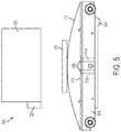
- FIG. 5 shows an embodiment of the printer of FIG. 1 having an air pump configured to inflate a planar member.
- FIG. 6 shows an embodiment of the method of FIG. 2 for operating the printer of FIG. 5 .
- the printer 100 includes an at least one actuator configured to deform the planar member 112 .
- the printer 100 further includes a controller 120 operably connected to the ejector head 108 and the actuator and the controller is configured to operate the ejector head 108 and the actuator.
- a method 200 for operating the printer 100 to automatically release printed parts from the platen 104 is shown in FIG. 2 .
- statements that the method is performing some task or function refers to a controller or general purpose processor executing programmed instructions stored in non-transitory computer readable storage media operatively connected to the controller or processor to manipulate data or to operate one or more components in the printer to perform the task or function.
- the controller 120 noted above can be such a controller or processor.
- the controller can be implemented with more than one processor and associated circuitry and components, each of which is configured to form one or more tasks or functions described herein.
- the method 200 begins by operating an ejector head to form a three-dimensional object on a planar member (block 204 ).
- the controller 120 operates the ejector head 108 to eject material onto the planar member 112 to form the part 116 .
- the method 200 operates an actuator to deform the planar member to release the three-dimensional object (block 208 ).
- the controller 120 operates the actuator to deform the planar member 112 .
- the method 200 operates the actuator to deform the planar member prior to forming the three-dimensional object on the planar member.
- FIG. 3 shows a printer 300 , which is one embodiment of the printer 100 , wherein the actuator comprises at least one roller configured to deform the planar member 112 by stretching it horizontally.
- “horizontally” refers to a direction that is parallel with the planar surface of the planar member 112 .
- a pair of rollers 304 is disposed at opposite ends of the platen 104 .
- the planar member 112 is attached at opposite ends to the pair of rollers 304 .
- the controller 120 is configured to operate the rollers 304 to stretch the planar member 112 horizontally along the surface of the platen. Stretching the planar member 112 causes localized shear forces to break any adhesion between the part 116 and the planar member 112 .
- the printer 100 releases the part 116 from platen 104 in an automated way that does not risk damaging the part.
- This particular embodiment of the printer 100 is operated using one of the methods 400 , 404 , and 408 , shown in FIGS. 4 a , 4 b , and 4 c , respectively.
- a method 400 for operating the printer 100 to automatically release printed parts from the platen 104 is shown in FIG. 4 a .
- the method 400 is an embodiment of the method 200 .
- the controller 120 operates at least one of the rollers 304 to relax the planar member 112 .
- “relax” refers to returning the planar member 112 to an un-deformed state.
- the method 400 operates an ejector head to form a three-dimensional object on the planar member (block 416 ).
- the controller 120 operates the ejector head 108 to eject material onto the planar member 112 to form the part 116 .
- the method 400 operates the roller to stretch the planar member to release the three-dimensional object (block 420 ).
- the controller 120 operates at least one of the rollers 304 to horizontally stretch the planar member 112 .
- the stretching of the planar member breaks any adhesion between the part 116 and the planar member 112 to release the part 116 .
- a method 404 for operating the printer 100 to automatically release printed parts from the platen 104 is shown in FIG. 4 b .
- the method 404 is an embodiment of the method 200 .
- the controller 120 operates at least one of the rollers 304 to horizontally stretch the planar member 112 .
- Pre-stretching the planar member 112 changes a surface roughness is of the planar member 112 during a subsequent formation of a part.
- the method 404 operates an ejector head to form a three-dimensional object on the planar member (block 428 ).
- the controller 120 operates the ejector head 108 to eject material onto the planar member 112 to form the part 116 .
- the method 404 operates the roller to relax the planar member to release the three-dimensional object (block 432 ).
- the controller 120 operates at least one of the rollers 304 to relax the planar member 112 .
- the relaxing of the planar member 112 breaks any adhesion between the part 116 and the planar member 112 to release the part 116 .
- a method 408 for operating the printer 100 to automatically release printed parts from the platen 104 is shown in FIG. 4 c .
- the method 408 is an embodiment of the method 200 .
- the controller 120 operates at least one of the rollers 304 to horizontally stretch the planar member 112 .
- the method 408 operates an ejector head to form a three-dimensional object on the planar member (block 440 ).
- the controller 120 operates the ejector head 108 to eject material onto the planar member 112 to form the part 116 .
- the method 408 operates the roller to stretch the planar member further and release the three-dimensional object (block 444 ).
- the controller 120 operates at least one of the rollers 304 to stretch the planar member 112 further. The further stretching of the planar member 112 breaks any adhesion between the part 116 and the planar member 112 to release the part 116 .
- FIG. 5 shows a printer 500 , which is another embodiment of the printer 100 , wherein the actuator comprises an air pump configured to direct air to inflate the planar member 112 .
- An air pump 504 is configured to direct air through openings 508 in an upper surface 512 of the platen 104 . Passages 516 extend through the platen 104 to connect the openings 508 to the air pump 504 .
- the planar member 112 is attached to the perimeter of the upper surface 512 of the platen 104 .
- the planar member 112 is configured as a balloon that is configured to inflate via a connection to the openings 508 .
- the controller 120 is configured to control the air pump 504 to direct air through the passages 516 and out the openings 508 . In this way, air collects between the upper surface 512 and the planar member 112 , causing the planar member 112 to inflate and stretch. Inflating the planar member 112 breaks any adhesion between the part 116 and the planar member 112 . In this way, the printer 100 releases the part 116 from platen 104 in an automated way that does not risk damaging the part. This particular embodiment of the printer 100 is operated using the method 600 .
- a method 600 for operating the printer 100 to automatically release printed parts from the platen 104 is shown in FIG. 6 .
- the method 600 is an embodiment of the method 200 .
- the controller 120 operates the ejector head 108 to eject material onto the planar member 112 to form the part 116 .
- the method 600 operates an air pump to inflate the planar member to release the three-dimensional object (block 608 ).
- the controller 120 operates the air pump 504 to direct air through the passages 516 and out the openings 508 , causing the planar member 112 to inflate.
- the inflating of the planar member 112 breaks any adhesion between the part 116 and the planar member 112 to release the part 116 .
Landscapes
- Chemical & Material Sciences (AREA)
- Engineering & Computer Science (AREA)
- Materials Engineering (AREA)
- Manufacturing & Machinery (AREA)
- Physics & Mathematics (AREA)
- Mechanical Engineering (AREA)
- Optics & Photonics (AREA)
- Handling Of Sheets (AREA)
Abstract
Description
Claims (4)
Priority Applications (1)
| Application Number | Priority Date | Filing Date | Title |
|---|---|---|---|
| US14/677,353 US10814551B2 (en) | 2015-04-02 | 2015-04-02 | Three-dimensional printed part removal using an elastomer sheet |
Applications Claiming Priority (1)
| Application Number | Priority Date | Filing Date | Title |
|---|---|---|---|
| US14/677,353 US10814551B2 (en) | 2015-04-02 | 2015-04-02 | Three-dimensional printed part removal using an elastomer sheet |
Publications (2)
| Publication Number | Publication Date |
|---|---|
| US20160288427A1 US20160288427A1 (en) | 2016-10-06 |
| US10814551B2 true US10814551B2 (en) | 2020-10-27 |
Family
ID=57015577
Family Applications (1)
| Application Number | Title | Priority Date | Filing Date |
|---|---|---|---|
| US14/677,353 Expired - Fee Related US10814551B2 (en) | 2015-04-02 | 2015-04-02 | Three-dimensional printed part removal using an elastomer sheet |
Country Status (1)
| Country | Link |
|---|---|
| US (1) | US10814551B2 (en) |
Families Citing this family (12)
| Publication number | Priority date | Publication date | Assignee | Title |
|---|---|---|---|---|
| WO2016025599A1 (en) * | 2014-08-12 | 2016-02-18 | Carbon3D, Inc. | Three-dimensional printing using carriers with release mechanisms |
| KR102455404B1 (en) | 2017-05-16 | 2022-10-14 | 트리아스텍 인코포레이티드 | 3D printing apparatus and method |
| EP3720687B1 (en) * | 2017-12-07 | 2025-02-12 | Formlabs, Inc. | Techniques for build platform part release in additive fabrication and related systems and methods |
| US10710303B2 (en) | 2017-12-07 | 2020-07-14 | Formlabs, Inc. | Techniques for build platform part release in additive fabrication and related systems and methods |
| US10201503B1 (en) | 2018-01-09 | 2019-02-12 | Triastek, Inc. | Precision pharmaceutical 3D printing device |
| US11458684B2 (en) | 2020-07-30 | 2022-10-04 | Triastek, Inc. | High-throughput and high-precision pharmaceutical additive manufacturing system |
| US12384112B2 (en) | 2019-08-20 | 2025-08-12 | Triastek, Inc. | High-throughput and high-precision pharmaceutical additive manufacturing system |
| EP4017702B1 (en) | 2019-08-20 | 2023-11-22 | Triastek, Inc. | Method and system for creating pharamceutical products by additive manufacturing |
| WO2021164660A1 (en) * | 2020-02-17 | 2021-08-26 | Triastek, Inc. | Continuous unloading and packaging system for pharmaceutical additive manufacturing |
| JP2023534179A (en) | 2020-07-10 | 2023-08-08 | トリアステック インコーポレイテッド | High-precision additive manufacturing equipment and high-throughput additive manufacturing system |
| CN117545614A (en) | 2021-06-25 | 2024-02-09 | 福姆实验室公司 | Techniques for releasing parts in additive manufacturing and related systems and methods |
| EP4519065A1 (en) * | 2021-12-21 | 2025-03-12 | Ehud Giloh | An adjustable shape changing printing bed for additive manufacturing |
Citations (19)
| Publication number | Priority date | Publication date | Assignee | Title |
|---|---|---|---|---|
| US4052217A (en) | 1971-11-09 | 1977-10-04 | Howson-Algraphy Limited | Bimetallic lithographic printing plates |
| US5094095A (en) | 1989-11-20 | 1992-03-10 | Koenig & Bauer Aktiengesellschaft | Printing plate bending apparatus |
| US5141680A (en) | 1988-04-18 | 1992-08-25 | 3D Systems, Inc. | Thermal stereolighography |
| US5171490A (en) * | 1988-11-29 | 1992-12-15 | Fudim Efrem V | Method and apparatus for production of three-dimensional objects by irradiation of photopolymers |
| US6269938B1 (en) | 1998-07-08 | 2001-08-07 | David W. Lutz | Over/under line feed system |
| US6571702B2 (en) * | 2000-11-29 | 2003-06-03 | Hewlett-Packard Company | Printer with vacuum platen having bimetallic valve sheet providing selectable active area |
| US20070063389A1 (en) * | 2001-04-23 | 2007-03-22 | Envisiontec Gmbh | Apparatus and method for the non-destructive separation of hardened material layers from a flat construction plane |
| US20110241947A1 (en) * | 2008-10-30 | 2011-10-06 | Mtt Technologies Limited | Additive manufacturing apparatus and method |
| US20120286453A1 (en) * | 2010-08-18 | 2012-11-15 | Pettis Nathaniel B | Networked three-dimensional printer with three-dimensional scanner |
| US20130241117A1 (en) * | 2012-03-14 | 2013-09-19 | Soeren Oemann Lind | Method of manufacturing an article by molding |
| US20140220168A1 (en) * | 2013-02-01 | 2014-08-07 | Massachusetts Institute Of Technology | Automated Three-Dimensional Printer Part Removal |
| US20140265032A1 (en) | 2013-03-14 | 2014-09-18 | Stratasys Ltd. | System and method for three-dimensional printing |
| US20140361463A1 (en) * | 2013-02-12 | 2014-12-11 | Eipi Systems, Inc. | Method and apparatus for three-dimensional fabrication |
| US8911199B2 (en) | 2013-02-28 | 2014-12-16 | Xerox Corporation | Cart with a support surface having a selectively adjustable contour and a printing system sheet stacker incorporating the cart |
| US20150192919A1 (en) * | 2015-03-24 | 2015-07-09 | Caterpillar Inc. | Support members for three dimensional object printing |
| US20150224710A1 (en) * | 2014-02-10 | 2015-08-13 | Global Filtration Systems, A Dba Of Gulf Filtration Systems Inc. | Apparatus and method for forming three-dimensional objects from solidifiable paste |
| US20160016361A1 (en) * | 2014-07-17 | 2016-01-21 | Formlabs, Inc. | Systems and methods for an improved peel operation during additive fabrication |
| US20160075091A1 (en) * | 2014-09-16 | 2016-03-17 | Eastman Chemical Company | Additive manufacturing object removal |
| US20160361868A1 (en) * | 2014-02-13 | 2016-12-15 | Empire Technology Development Llc | Methods and apparatuses for additive manufacturing |
-
2015
- 2015-04-02 US US14/677,353 patent/US10814551B2/en not_active Expired - Fee Related
Patent Citations (19)
| Publication number | Priority date | Publication date | Assignee | Title |
|---|---|---|---|---|
| US4052217A (en) | 1971-11-09 | 1977-10-04 | Howson-Algraphy Limited | Bimetallic lithographic printing plates |
| US5141680A (en) | 1988-04-18 | 1992-08-25 | 3D Systems, Inc. | Thermal stereolighography |
| US5171490A (en) * | 1988-11-29 | 1992-12-15 | Fudim Efrem V | Method and apparatus for production of three-dimensional objects by irradiation of photopolymers |
| US5094095A (en) | 1989-11-20 | 1992-03-10 | Koenig & Bauer Aktiengesellschaft | Printing plate bending apparatus |
| US6269938B1 (en) | 1998-07-08 | 2001-08-07 | David W. Lutz | Over/under line feed system |
| US6571702B2 (en) * | 2000-11-29 | 2003-06-03 | Hewlett-Packard Company | Printer with vacuum platen having bimetallic valve sheet providing selectable active area |
| US20070063389A1 (en) * | 2001-04-23 | 2007-03-22 | Envisiontec Gmbh | Apparatus and method for the non-destructive separation of hardened material layers from a flat construction plane |
| US20110241947A1 (en) * | 2008-10-30 | 2011-10-06 | Mtt Technologies Limited | Additive manufacturing apparatus and method |
| US20120286453A1 (en) * | 2010-08-18 | 2012-11-15 | Pettis Nathaniel B | Networked three-dimensional printer with three-dimensional scanner |
| US20130241117A1 (en) * | 2012-03-14 | 2013-09-19 | Soeren Oemann Lind | Method of manufacturing an article by molding |
| US20140220168A1 (en) * | 2013-02-01 | 2014-08-07 | Massachusetts Institute Of Technology | Automated Three-Dimensional Printer Part Removal |
| US20140361463A1 (en) * | 2013-02-12 | 2014-12-11 | Eipi Systems, Inc. | Method and apparatus for three-dimensional fabrication |
| US8911199B2 (en) | 2013-02-28 | 2014-12-16 | Xerox Corporation | Cart with a support surface having a selectively adjustable contour and a printing system sheet stacker incorporating the cart |
| US20140265032A1 (en) | 2013-03-14 | 2014-09-18 | Stratasys Ltd. | System and method for three-dimensional printing |
| US20150224710A1 (en) * | 2014-02-10 | 2015-08-13 | Global Filtration Systems, A Dba Of Gulf Filtration Systems Inc. | Apparatus and method for forming three-dimensional objects from solidifiable paste |
| US20160361868A1 (en) * | 2014-02-13 | 2016-12-15 | Empire Technology Development Llc | Methods and apparatuses for additive manufacturing |
| US20160016361A1 (en) * | 2014-07-17 | 2016-01-21 | Formlabs, Inc. | Systems and methods for an improved peel operation during additive fabrication |
| US20160075091A1 (en) * | 2014-09-16 | 2016-03-17 | Eastman Chemical Company | Additive manufacturing object removal |
| US20150192919A1 (en) * | 2015-03-24 | 2015-07-09 | Caterpillar Inc. | Support members for three dimensional object printing |
Also Published As
| Publication number | Publication date |
|---|---|
| US20160288427A1 (en) | 2016-10-06 |
Similar Documents
| Publication | Publication Date | Title |
|---|---|---|
| US10814551B2 (en) | Three-dimensional printed part removal using an elastomer sheet | |
| US9884449B2 (en) | Three-dimensional printed part removal using an interlaced platen | |
| US10471700B2 (en) | Three-dimensional object manufacturing apparatus and control method for the same | |
| US11318666B2 (en) | System for removing support structure using integrated fluid paths | |
| US9751263B2 (en) | Injection molding to finish parts printed with a three-dimensional object printer | |
| US10906244B2 (en) | Ultrasonic removal methods of three-dimensionally printed parts | |
| US11654623B2 (en) | Additive manufacturing system with layers of reinforcing mesh | |
| US10000051B2 (en) | System and method for removing three-dimensional printed parts from a platen using inductive heating and gravity | |
| CN105636765A (en) | Three-dimensional shaping device and method for forming three-dimensional shaping device | |
| US20170129183A1 (en) | System and method for removing support structure from three-dimensional printed objects using microwave energy and nanoparticles | |
| JP2009097096A (en) | Method for removing glove from mold, and device for removing glove from mold used for the method | |
| JP2015160422A (en) | Deburring device for synthetic resin molding equipped with robot arm | |
| US9381701B1 (en) | Printer and method for releasing three-dimensionally printed parts from a platen using actuators | |
| US20180001545A1 (en) | Multiple support materials for accelerated post-processing of three-dimensionally printed objects | |
| JP2020059138A5 (en) | ||
| JP2012192556A5 (en) | ||
| JP2019118663A5 (en) | ||
| CN106560314B (en) | System and method for orthogonally arranging jets in a three-dimensional object printer | |
| JP6697639B2 (en) | Automatic protective sheet peeling device and protective sheet automatic peeling method | |
| US20190308377A1 (en) | Composite Laminate Forming Apparatus and Method Therefor | |
| JP2016004837A5 (en) | Imprint apparatus, imprint method, article manufacturing method, and supply apparatus | |
| CN204487676U (en) | Intelligence gets product machine | |
| CN104786659B (en) | The cleaning method of ink-jet printer | |
| CN106488807B (en) | For the template of the surface structuration of etching technique | |
| JP2018022960A5 (en) |
Legal Events
| Date | Code | Title | Description |
|---|---|---|---|
| AS | Assignment |
Owner name: XEROX CORPORATION, CONNECTICUT Free format text: ASSIGNMENT OF ASSIGNORS INTEREST;ASSIGNORS:ANDERSON, ROBERT B, JR;ROBLES FLORES, ELUID;FOLEY, TIMOTHY P;REEL/FRAME:035322/0668 Effective date: 20150217 |
|
| AS | Assignment |
Owner name: XEROX CORPORATION, CONNECTICUT Free format text: ASSIGNMENT OF ASSIGNORS INTEREST;ASSIGNORS:ANDERSON, ROBERT B., JR.;FLORES, ELIUD R.;FOLEY, TIMOTHY P.;REEL/FRAME:035337/0155 Effective date: 20150217 |
|
| STPP | Information on status: patent application and granting procedure in general |
Free format text: FINAL REJECTION MAILED |
|
| STPP | Information on status: patent application and granting procedure in general |
Free format text: RESPONSE AFTER FINAL ACTION FORWARDED TO EXAMINER |
|
| STPP | Information on status: patent application and granting procedure in general |
Free format text: ADVISORY ACTION MAILED |
|
| STCV | Information on status: appeal procedure |
Free format text: NOTICE OF APPEAL FILED |
|
| STCV | Information on status: appeal procedure |
Free format text: APPEAL BRIEF (OR SUPPLEMENTAL BRIEF) ENTERED AND FORWARDED TO EXAMINER |
|
| STPP | Information on status: patent application and granting procedure in general |
Free format text: NON FINAL ACTION MAILED |
|
| STCV | Information on status: appeal procedure |
Free format text: NOTICE OF APPEAL FILED |
|
| STCV | Information on status: appeal procedure |
Free format text: APPEAL BRIEF (OR SUPPLEMENTAL BRIEF) ENTERED AND FORWARDED TO EXAMINER |
|
| STPP | Information on status: patent application and granting procedure in general |
Free format text: NOTICE OF ALLOWANCE MAILED -- APPLICATION RECEIVED IN OFFICE OF PUBLICATIONS |
|
| ZAAA | Notice of allowance and fees due |
Free format text: ORIGINAL CODE: NOA |
|
| ZAAB | Notice of allowance mailed |
Free format text: ORIGINAL CODE: MN/=. |
|
| STCF | Information on status: patent grant |
Free format text: PATENTED CASE |
|
| AS | Assignment |
Owner name: CITIBANK, N.A., AS AGENT, DELAWARE Free format text: SECURITY INTEREST;ASSIGNOR:XEROX CORPORATION;REEL/FRAME:062740/0214 Effective date: 20221107 |
|
| AS | Assignment |
Owner name: XEROX CORPORATION, CONNECTICUT Free format text: RELEASE OF SECURITY INTEREST IN PATENTS AT R/F 062740/0214;ASSIGNOR:CITIBANK, N.A., AS AGENT;REEL/FRAME:063694/0122 Effective date: 20230517 |
|
| AS | Assignment |
Owner name: CITIBANK, N.A., AS COLLATERAL AGENT, NEW YORK Free format text: SECURITY INTEREST;ASSIGNOR:XEROX CORPORATION;REEL/FRAME:064760/0389 Effective date: 20230621 |
|
| AS | Assignment |
Owner name: JEFFERIES FINANCE LLC, AS COLLATERAL AGENT, NEW YORK Free format text: SECURITY INTEREST;ASSIGNOR:XEROX CORPORATION;REEL/FRAME:065628/0019 Effective date: 20231117 |
|
| AS | Assignment |
Owner name: XEROX CORPORATION, CONNECTICUT Free format text: TERMINATION AND RELEASE OF SECURITY INTEREST IN PATENTS RECORDED AT RF 064760/0389;ASSIGNOR:CITIBANK, N.A., AS COLLATERAL AGENT;REEL/FRAME:068261/0001 Effective date: 20240206 Owner name: CITIBANK, N.A., AS COLLATERAL AGENT, NEW YORK Free format text: SECURITY INTEREST;ASSIGNOR:XEROX CORPORATION;REEL/FRAME:066741/0001 Effective date: 20240206 |
|
| FEPP | Fee payment procedure |
Free format text: MAINTENANCE FEE REMINDER MAILED (ORIGINAL EVENT CODE: REM.); ENTITY STATUS OF PATENT OWNER: LARGE ENTITY |
|
| LAPS | Lapse for failure to pay maintenance fees |
Free format text: PATENT EXPIRED FOR FAILURE TO PAY MAINTENANCE FEES (ORIGINAL EVENT CODE: EXP.); ENTITY STATUS OF PATENT OWNER: LARGE ENTITY |
|
| STCH | Information on status: patent discontinuation |
Free format text: PATENT EXPIRED DUE TO NONPAYMENT OF MAINTENANCE FEES UNDER 37 CFR 1.362 |
|
| FP | Lapsed due to failure to pay maintenance fee |
Effective date: 20241027 |