US10813761B2 - Tethered implantable device having a vortical intracardiac velocity adjusting balloon - Google Patents
Tethered implantable device having a vortical intracardiac velocity adjusting balloon Download PDFInfo
- Publication number
- US10813761B2 US10813761B2 US15/987,621 US201815987621A US10813761B2 US 10813761 B2 US10813761 B2 US 10813761B2 US 201815987621 A US201815987621 A US 201815987621A US 10813761 B2 US10813761 B2 US 10813761B2
- Authority
- US
- United States
- Prior art keywords
- implant system
- balloon
- shaft
- base plate
- proximal
- Prior art date
- Legal status (The legal status is an assumption and is not a legal conclusion. Google has not performed a legal analysis and makes no representation as to the accuracy of the status listed.)
- Expired - Fee Related
Links
- 239000007943 implant Substances 0.000 claims abstract description 33
- 239000012530 fluid Substances 0.000 claims abstract description 19
- 238000004891 communication Methods 0.000 claims description 9
- 230000017531 blood circulation Effects 0.000 claims description 5
- 229920000295 expanded polytetrafluoroethylene Polymers 0.000 claims description 3
- 229920004934 Dacron® Polymers 0.000 claims description 2
- 239000007788 liquid Substances 0.000 claims description 2
- 239000005020 polyethylene terephthalate Substances 0.000 claims description 2
- 229920000642 polymer Polymers 0.000 claims 2
- 230000014759 maintenance of location Effects 0.000 claims 1
- 230000001225 therapeutic effect Effects 0.000 abstract description 13
- 230000002861 ventricular Effects 0.000 description 40
- 230000000004 hemodynamic effect Effects 0.000 description 17
- 239000008280 blood Substances 0.000 description 16
- 210000004369 blood Anatomy 0.000 description 16
- 210000002837 heart atrium Anatomy 0.000 description 7
- 230000003205 diastolic effect Effects 0.000 description 6
- 230000008859 change Effects 0.000 description 5
- 239000000463 material Substances 0.000 description 5
- 230000000694 effects Effects 0.000 description 4
- 210000001174 endocardium Anatomy 0.000 description 4
- 238000000034 method Methods 0.000 description 4
- 230000001746 atrial effect Effects 0.000 description 3
- 230000015572 biosynthetic process Effects 0.000 description 3
- 230000000747 cardiac effect Effects 0.000 description 3
- 230000007423 decrease Effects 0.000 description 3
- 206010056370 Congestive cardiomyopathy Diseases 0.000 description 2
- 201000010046 Dilated cardiomyopathy Diseases 0.000 description 2
- 210000003484 anatomy Anatomy 0.000 description 2
- 238000004873 anchoring Methods 0.000 description 2
- 230000008901 benefit Effects 0.000 description 2
- 238000010586 diagram Methods 0.000 description 2
- 210000005248 left atrial appendage Anatomy 0.000 description 2
- 238000012986 modification Methods 0.000 description 2
- 230000004048 modification Effects 0.000 description 2
- 210000003540 papillary muscle Anatomy 0.000 description 2
- 230000007170 pathology Effects 0.000 description 2
- 230000008439 repair process Effects 0.000 description 2
- 210000001519 tissue Anatomy 0.000 description 2
- 238000012546 transfer Methods 0.000 description 2
- 208000007536 Thrombosis Diseases 0.000 description 1
- 208000009982 Ventricular Dysfunction Diseases 0.000 description 1
- 230000002159 abnormal effect Effects 0.000 description 1
- 238000007792 addition Methods 0.000 description 1
- 210000005242 cardiac chamber Anatomy 0.000 description 1
- 230000001010 compromised effect Effects 0.000 description 1
- 230000008602 contraction Effects 0.000 description 1
- 238000013500 data storage Methods 0.000 description 1
- 230000003247 decreasing effect Effects 0.000 description 1
- 230000007547 defect Effects 0.000 description 1
- 230000003073 embolic effect Effects 0.000 description 1
- 230000006870 function Effects 0.000 description 1
- 230000004217 heart function Effects 0.000 description 1
- 230000023597 hemostasis Effects 0.000 description 1
- 230000003116 impacting effect Effects 0.000 description 1
- 238000002513 implantation Methods 0.000 description 1
- 208000015181 infectious disease Diseases 0.000 description 1
- 230000003993 interaction Effects 0.000 description 1
- 238000007914 intraventricular administration Methods 0.000 description 1
- 230000007774 longterm Effects 0.000 description 1
- 230000007246 mechanism Effects 0.000 description 1
- 230000003387 muscular Effects 0.000 description 1
- 238000002559 palpation Methods 0.000 description 1
- 229920001296 polysiloxane Polymers 0.000 description 1
- 239000011148 porous material Substances 0.000 description 1
- 230000009467 reduction Effects 0.000 description 1
- 238000007634 remodeling Methods 0.000 description 1
- 238000004904 shortening Methods 0.000 description 1
- 230000026683 transduction Effects 0.000 description 1
- 238000010361 transduction Methods 0.000 description 1
- 230000006815 ventricular dysfunction Effects 0.000 description 1
Images


Classifications
-
- A—HUMAN NECESSITIES
- A61—MEDICAL OR VETERINARY SCIENCE; HYGIENE
- A61B—DIAGNOSIS; SURGERY; IDENTIFICATION
- A61B17/00—Surgical instruments, devices or methods
- A61B17/12—Surgical instruments, devices or methods for ligaturing or otherwise compressing tubular parts of the body, e.g. blood vessels or umbilical cord
- A61B17/12022—Occluding by internal devices, e.g. balloons or releasable wires
- A61B17/12099—Occluding by internal devices, e.g. balloons or releasable wires characterised by the location of the occluder
- A61B17/12122—Occluding by internal devices, e.g. balloons or releasable wires characterised by the location of the occluder within the heart
-
- A—HUMAN NECESSITIES
- A61—MEDICAL OR VETERINARY SCIENCE; HYGIENE
- A61F—FILTERS IMPLANTABLE INTO BLOOD VESSELS; PROSTHESES; DEVICES PROVIDING PATENCY TO, OR PREVENTING COLLAPSING OF, TUBULAR STRUCTURES OF THE BODY, e.g. STENTS; ORTHOPAEDIC, NURSING OR CONTRACEPTIVE DEVICES; FOMENTATION; TREATMENT OR PROTECTION OF EYES OR EARS; BANDAGES, DRESSINGS OR ABSORBENT PADS; FIRST-AID KITS
- A61F2/00—Filters implantable into blood vessels; Prostheses, i.e. artificial substitutes or replacements for parts of the body; Appliances for connecting them with the body; Devices providing patency to, or preventing collapsing of, tubular structures of the body, e.g. stents
- A61F2/02—Prostheses implantable into the body
- A61F2/24—Heart valves ; Vascular valves, e.g. venous valves; Heart implants, e.g. passive devices for improving the function of the native valve or the heart muscle; Transmyocardial revascularisation [TMR] devices; Valves implantable in the body
- A61F2/2478—Passive devices for improving the function of the heart muscle, i.e. devices for reshaping the external surface of the heart, e.g. bags, strips or bands
- A61F2/2487—Devices within the heart chamber, e.g. splints
-
- A—HUMAN NECESSITIES
- A61—MEDICAL OR VETERINARY SCIENCE; HYGIENE
- A61B—DIAGNOSIS; SURGERY; IDENTIFICATION
- A61B17/00—Surgical instruments, devices or methods
- A61B17/12—Surgical instruments, devices or methods for ligaturing or otherwise compressing tubular parts of the body, e.g. blood vessels or umbilical cord
- A61B17/12022—Occluding by internal devices, e.g. balloons or releasable wires
- A61B17/12131—Occluding by internal devices, e.g. balloons or releasable wires characterised by the type of occluding device
- A61B17/12136—Balloons
-
- A—HUMAN NECESSITIES
- A61—MEDICAL OR VETERINARY SCIENCE; HYGIENE
- A61F—FILTERS IMPLANTABLE INTO BLOOD VESSELS; PROSTHESES; DEVICES PROVIDING PATENCY TO, OR PREVENTING COLLAPSING OF, TUBULAR STRUCTURES OF THE BODY, e.g. STENTS; ORTHOPAEDIC, NURSING OR CONTRACEPTIVE DEVICES; FOMENTATION; TREATMENT OR PROTECTION OF EYES OR EARS; BANDAGES, DRESSINGS OR ABSORBENT PADS; FIRST-AID KITS
- A61F2/00—Filters implantable into blood vessels; Prostheses, i.e. artificial substitutes or replacements for parts of the body; Appliances for connecting them with the body; Devices providing patency to, or preventing collapsing of, tubular structures of the body, e.g. stents
- A61F2/02—Prostheses implantable into the body
- A61F2/24—Heart valves ; Vascular valves, e.g. venous valves; Heart implants, e.g. passive devices for improving the function of the native valve or the heart muscle; Transmyocardial revascularisation [TMR] devices; Valves implantable in the body
- A61F2/2412—Heart valves ; Vascular valves, e.g. venous valves; Heart implants, e.g. passive devices for improving the function of the native valve or the heart muscle; Transmyocardial revascularisation [TMR] devices; Valves implantable in the body with soft flexible valve members, e.g. tissue valves shaped like natural valves
-
- A—HUMAN NECESSITIES
- A61—MEDICAL OR VETERINARY SCIENCE; HYGIENE
- A61F—FILTERS IMPLANTABLE INTO BLOOD VESSELS; PROSTHESES; DEVICES PROVIDING PATENCY TO, OR PREVENTING COLLAPSING OF, TUBULAR STRUCTURES OF THE BODY, e.g. STENTS; ORTHOPAEDIC, NURSING OR CONTRACEPTIVE DEVICES; FOMENTATION; TREATMENT OR PROTECTION OF EYES OR EARS; BANDAGES, DRESSINGS OR ABSORBENT PADS; FIRST-AID KITS
- A61F2/00—Filters implantable into blood vessels; Prostheses, i.e. artificial substitutes or replacements for parts of the body; Appliances for connecting them with the body; Devices providing patency to, or preventing collapsing of, tubular structures of the body, e.g. stents
- A61F2/02—Prostheses implantable into the body
- A61F2/24—Heart valves ; Vascular valves, e.g. venous valves; Heart implants, e.g. passive devices for improving the function of the native valve or the heart muscle; Transmyocardial revascularisation [TMR] devices; Valves implantable in the body
- A61F2/2427—Devices for manipulating or deploying heart valves during implantation
- A61F2/243—Deployment by mechanical expansion
- A61F2/2433—Deployment by mechanical expansion using balloon catheter
-
- A—HUMAN NECESSITIES
- A61—MEDICAL OR VETERINARY SCIENCE; HYGIENE
- A61F—FILTERS IMPLANTABLE INTO BLOOD VESSELS; PROSTHESES; DEVICES PROVIDING PATENCY TO, OR PREVENTING COLLAPSING OF, TUBULAR STRUCTURES OF THE BODY, e.g. STENTS; ORTHOPAEDIC, NURSING OR CONTRACEPTIVE DEVICES; FOMENTATION; TREATMENT OR PROTECTION OF EYES OR EARS; BANDAGES, DRESSINGS OR ABSORBENT PADS; FIRST-AID KITS
- A61F2/00—Filters implantable into blood vessels; Prostheses, i.e. artificial substitutes or replacements for parts of the body; Appliances for connecting them with the body; Devices providing patency to, or preventing collapsing of, tubular structures of the body, e.g. stents
- A61F2/02—Prostheses implantable into the body
- A61F2/24—Heart valves ; Vascular valves, e.g. venous valves; Heart implants, e.g. passive devices for improving the function of the native valve or the heart muscle; Transmyocardial revascularisation [TMR] devices; Valves implantable in the body
- A61F2/2442—Annuloplasty rings or inserts for correcting the valve shape; Implants for improving the function of a native heart valve
-
- A—HUMAN NECESSITIES
- A61—MEDICAL OR VETERINARY SCIENCE; HYGIENE
- A61B—DIAGNOSIS; SURGERY; IDENTIFICATION
- A61B17/00—Surgical instruments, devices or methods
- A61B17/00234—Surgical instruments, devices or methods for minimally invasive surgery
-
- A—HUMAN NECESSITIES
- A61—MEDICAL OR VETERINARY SCIENCE; HYGIENE
- A61B—DIAGNOSIS; SURGERY; IDENTIFICATION
- A61B17/00—Surgical instruments, devices or methods
- A61B2017/00017—Electrical control of surgical instruments
-
- A—HUMAN NECESSITIES
- A61—MEDICAL OR VETERINARY SCIENCE; HYGIENE
- A61B—DIAGNOSIS; SURGERY; IDENTIFICATION
- A61B17/00—Surgical instruments, devices or methods
- A61B2017/00017—Electrical control of surgical instruments
- A61B2017/00022—Sensing or detecting at the treatment site
-
- A—HUMAN NECESSITIES
- A61—MEDICAL OR VETERINARY SCIENCE; HYGIENE
- A61B—DIAGNOSIS; SURGERY; IDENTIFICATION
- A61B17/00—Surgical instruments, devices or methods
- A61B2017/00017—Electrical control of surgical instruments
- A61B2017/00221—Electrical control of surgical instruments with wireless transmission of data, e.g. by infrared radiation or radiowaves
-
- A—HUMAN NECESSITIES
- A61—MEDICAL OR VETERINARY SCIENCE; HYGIENE
- A61B—DIAGNOSIS; SURGERY; IDENTIFICATION
- A61B17/00—Surgical instruments, devices or methods
- A61B17/00234—Surgical instruments, devices or methods for minimally invasive surgery
- A61B2017/00238—Type of minimally invasive operation
- A61B2017/00243—Type of minimally invasive operation cardiac
-
- A—HUMAN NECESSITIES
- A61—MEDICAL OR VETERINARY SCIENCE; HYGIENE
- A61B—DIAGNOSIS; SURGERY; IDENTIFICATION
- A61B17/00—Surgical instruments, devices or methods
- A61B2017/00535—Surgical instruments, devices or methods pneumatically or hydraulically operated
- A61B2017/00539—Surgical instruments, devices or methods pneumatically or hydraulically operated hydraulically
-
- A—HUMAN NECESSITIES
- A61—MEDICAL OR VETERINARY SCIENCE; HYGIENE
- A61B—DIAGNOSIS; SURGERY; IDENTIFICATION
- A61B17/00—Surgical instruments, devices or methods
- A61B2017/00535—Surgical instruments, devices or methods pneumatically or hydraulically operated
- A61B2017/00557—Surgical instruments, devices or methods pneumatically or hydraulically operated inflatable
-
- A—HUMAN NECESSITIES
- A61—MEDICAL OR VETERINARY SCIENCE; HYGIENE
- A61B—DIAGNOSIS; SURGERY; IDENTIFICATION
- A61B17/00—Surgical instruments, devices or methods
- A61B17/34—Trocars; Puncturing needles
- A61B17/3417—Details of tips or shafts, e.g. grooves, expandable, bendable; Multiple coaxial sliding cannulas, e.g. for dilating
- A61B17/3421—Cannulas
- A61B17/3423—Access ports, e.g. toroid shape introducers for instruments or hands
- A61B2017/3425—Access ports, e.g. toroid shape introducers for instruments or hands for internal organs, e.g. heart ports
-
- A—HUMAN NECESSITIES
- A61—MEDICAL OR VETERINARY SCIENCE; HYGIENE
- A61B—DIAGNOSIS; SURGERY; IDENTIFICATION
- A61B90/00—Instruments, implements or accessories specially adapted for surgery or diagnosis and not covered by any of the groups A61B1/00 - A61B50/00, e.g. for luxation treatment or for protecting wound edges
- A61B90/03—Automatic limiting or abutting means, e.g. for safety
- A61B2090/033—Abutting means, stops, e.g. abutting on tissue or skin
- A61B2090/036—Abutting means, stops, e.g. abutting on tissue or skin abutting on tissue or skin
-
- A—HUMAN NECESSITIES
- A61—MEDICAL OR VETERINARY SCIENCE; HYGIENE
- A61F—FILTERS IMPLANTABLE INTO BLOOD VESSELS; PROSTHESES; DEVICES PROVIDING PATENCY TO, OR PREVENTING COLLAPSING OF, TUBULAR STRUCTURES OF THE BODY, e.g. STENTS; ORTHOPAEDIC, NURSING OR CONTRACEPTIVE DEVICES; FOMENTATION; TREATMENT OR PROTECTION OF EYES OR EARS; BANDAGES, DRESSINGS OR ABSORBENT PADS; FIRST-AID KITS
- A61F2/00—Filters implantable into blood vessels; Prostheses, i.e. artificial substitutes or replacements for parts of the body; Appliances for connecting them with the body; Devices providing patency to, or preventing collapsing of, tubular structures of the body, e.g. stents
- A61F2/02—Prostheses implantable into the body
- A61F2/48—Operating or control means, e.g. from outside the body, control of sphincters
- A61F2/482—Electrical means
-
- A—HUMAN NECESSITIES
- A61—MEDICAL OR VETERINARY SCIENCE; HYGIENE
- A61F—FILTERS IMPLANTABLE INTO BLOOD VESSELS; PROSTHESES; DEVICES PROVIDING PATENCY TO, OR PREVENTING COLLAPSING OF, TUBULAR STRUCTURES OF THE BODY, e.g. STENTS; ORTHOPAEDIC, NURSING OR CONTRACEPTIVE DEVICES; FOMENTATION; TREATMENT OR PROTECTION OF EYES OR EARS; BANDAGES, DRESSINGS OR ABSORBENT PADS; FIRST-AID KITS
- A61F2/00—Filters implantable into blood vessels; Prostheses, i.e. artificial substitutes or replacements for parts of the body; Appliances for connecting them with the body; Devices providing patency to, or preventing collapsing of, tubular structures of the body, e.g. stents
- A61F2/02—Prostheses implantable into the body
- A61F2/48—Operating or control means, e.g. from outside the body, control of sphincters
- A61F2/484—Fluid means, i.e. hydraulic or pneumatic
-
- A—HUMAN NECESSITIES
- A61—MEDICAL OR VETERINARY SCIENCE; HYGIENE
- A61F—FILTERS IMPLANTABLE INTO BLOOD VESSELS; PROSTHESES; DEVICES PROVIDING PATENCY TO, OR PREVENTING COLLAPSING OF, TUBULAR STRUCTURES OF THE BODY, e.g. STENTS; ORTHOPAEDIC, NURSING OR CONTRACEPTIVE DEVICES; FOMENTATION; TREATMENT OR PROTECTION OF EYES OR EARS; BANDAGES, DRESSINGS OR ABSORBENT PADS; FIRST-AID KITS
- A61F2/00—Filters implantable into blood vessels; Prostheses, i.e. artificial substitutes or replacements for parts of the body; Appliances for connecting them with the body; Devices providing patency to, or preventing collapsing of, tubular structures of the body, e.g. stents
- A61F2/02—Prostheses implantable into the body
- A61F2/04—Hollow or tubular parts of organs, e.g. bladders, tracheae, bronchi or bile ducts
- A61F2/06—Blood vessels
- A61F2002/068—Modifying the blood flow model, e.g. by diffuser or deflector
-
- A61F2002/482—
-
- A61F2002/485—
-
- A—HUMAN NECESSITIES
- A61—MEDICAL OR VETERINARY SCIENCE; HYGIENE
- A61F—FILTERS IMPLANTABLE INTO BLOOD VESSELS; PROSTHESES; DEVICES PROVIDING PATENCY TO, OR PREVENTING COLLAPSING OF, TUBULAR STRUCTURES OF THE BODY, e.g. STENTS; ORTHOPAEDIC, NURSING OR CONTRACEPTIVE DEVICES; FOMENTATION; TREATMENT OR PROTECTION OF EYES OR EARS; BANDAGES, DRESSINGS OR ABSORBENT PADS; FIRST-AID KITS
- A61F2210/00—Particular material properties of prostheses classified in groups A61F2/00 - A61F2/26 or A61F2/82 or A61F9/00 or A61F11/00 or subgroups thereof
- A61F2210/009—Particular material properties of prostheses classified in groups A61F2/00 - A61F2/26 or A61F2/82 or A61F9/00 or A61F11/00 or subgroups thereof magnetic
-
- A—HUMAN NECESSITIES
- A61—MEDICAL OR VETERINARY SCIENCE; HYGIENE
- A61F—FILTERS IMPLANTABLE INTO BLOOD VESSELS; PROSTHESES; DEVICES PROVIDING PATENCY TO, OR PREVENTING COLLAPSING OF, TUBULAR STRUCTURES OF THE BODY, e.g. STENTS; ORTHOPAEDIC, NURSING OR CONTRACEPTIVE DEVICES; FOMENTATION; TREATMENT OR PROTECTION OF EYES OR EARS; BANDAGES, DRESSINGS OR ABSORBENT PADS; FIRST-AID KITS
- A61F2220/00—Fixations or connections for prostheses classified in groups A61F2/00 - A61F2/26 or A61F2/82 or A61F9/00 or A61F11/00 or subgroups thereof
- A61F2220/0008—Fixation appliances for connecting prostheses to the body
-
- A—HUMAN NECESSITIES
- A61—MEDICAL OR VETERINARY SCIENCE; HYGIENE
- A61F—FILTERS IMPLANTABLE INTO BLOOD VESSELS; PROSTHESES; DEVICES PROVIDING PATENCY TO, OR PREVENTING COLLAPSING OF, TUBULAR STRUCTURES OF THE BODY, e.g. STENTS; ORTHOPAEDIC, NURSING OR CONTRACEPTIVE DEVICES; FOMENTATION; TREATMENT OR PROTECTION OF EYES OR EARS; BANDAGES, DRESSINGS OR ABSORBENT PADS; FIRST-AID KITS
- A61F2220/00—Fixations or connections for prostheses classified in groups A61F2/00 - A61F2/26 or A61F2/82 or A61F9/00 or A61F11/00 or subgroups thereof
- A61F2220/0025—Connections or couplings between prosthetic parts, e.g. between modular parts; Connecting elements
- A61F2220/0033—Connections or couplings between prosthetic parts, e.g. between modular parts; Connecting elements made by longitudinally pushing a protrusion into a complementary-shaped recess, e.g. held by friction fit
-
- A—HUMAN NECESSITIES
- A61—MEDICAL OR VETERINARY SCIENCE; HYGIENE
- A61F—FILTERS IMPLANTABLE INTO BLOOD VESSELS; PROSTHESES; DEVICES PROVIDING PATENCY TO, OR PREVENTING COLLAPSING OF, TUBULAR STRUCTURES OF THE BODY, e.g. STENTS; ORTHOPAEDIC, NURSING OR CONTRACEPTIVE DEVICES; FOMENTATION; TREATMENT OR PROTECTION OF EYES OR EARS; BANDAGES, DRESSINGS OR ABSORBENT PADS; FIRST-AID KITS
- A61F2220/00—Fixations or connections for prostheses classified in groups A61F2/00 - A61F2/26 or A61F2/82 or A61F9/00 or A61F11/00 or subgroups thereof
- A61F2220/0025—Connections or couplings between prosthetic parts, e.g. between modular parts; Connecting elements
- A61F2220/0091—Connections or couplings between prosthetic parts, e.g. between modular parts; Connecting elements connected by a hinged linkage mechanism, e.g. of the single-bar or multi-bar linkage type
-
- A—HUMAN NECESSITIES
- A61—MEDICAL OR VETERINARY SCIENCE; HYGIENE
- A61F—FILTERS IMPLANTABLE INTO BLOOD VESSELS; PROSTHESES; DEVICES PROVIDING PATENCY TO, OR PREVENTING COLLAPSING OF, TUBULAR STRUCTURES OF THE BODY, e.g. STENTS; ORTHOPAEDIC, NURSING OR CONTRACEPTIVE DEVICES; FOMENTATION; TREATMENT OR PROTECTION OF EYES OR EARS; BANDAGES, DRESSINGS OR ABSORBENT PADS; FIRST-AID KITS
- A61F2230/00—Geometry of prostheses classified in groups A61F2/00 - A61F2/26 or A61F2/82 or A61F9/00 or A61F11/00 or subgroups thereof
- A61F2230/0002—Two-dimensional shapes, e.g. cross-sections
- A61F2230/0004—Rounded shapes, e.g. with rounded corners
- A61F2230/0013—Horseshoe-shaped, e.g. crescent-shaped, C-shaped, U-shaped
-
- A—HUMAN NECESSITIES
- A61—MEDICAL OR VETERINARY SCIENCE; HYGIENE
- A61F—FILTERS IMPLANTABLE INTO BLOOD VESSELS; PROSTHESES; DEVICES PROVIDING PATENCY TO, OR PREVENTING COLLAPSING OF, TUBULAR STRUCTURES OF THE BODY, e.g. STENTS; ORTHOPAEDIC, NURSING OR CONTRACEPTIVE DEVICES; FOMENTATION; TREATMENT OR PROTECTION OF EYES OR EARS; BANDAGES, DRESSINGS OR ABSORBENT PADS; FIRST-AID KITS
- A61F2250/00—Special features of prostheses classified in groups A61F2/00 - A61F2/26 or A61F2/82 or A61F9/00 or A61F11/00 or subgroups thereof
- A61F2250/0003—Special features of prostheses classified in groups A61F2/00 - A61F2/26 or A61F2/82 or A61F9/00 or A61F11/00 or subgroups thereof having an inflatable pocket filled with fluid, e.g. liquid or gas
-
- A—HUMAN NECESSITIES
- A61—MEDICAL OR VETERINARY SCIENCE; HYGIENE
- A61F—FILTERS IMPLANTABLE INTO BLOOD VESSELS; PROSTHESES; DEVICES PROVIDING PATENCY TO, OR PREVENTING COLLAPSING OF, TUBULAR STRUCTURES OF THE BODY, e.g. STENTS; ORTHOPAEDIC, NURSING OR CONTRACEPTIVE DEVICES; FOMENTATION; TREATMENT OR PROTECTION OF EYES OR EARS; BANDAGES, DRESSINGS OR ABSORBENT PADS; FIRST-AID KITS
- A61F2250/00—Special features of prostheses classified in groups A61F2/00 - A61F2/26 or A61F2/82 or A61F9/00 or A61F11/00 or subgroups thereof
- A61F2250/0004—Special features of prostheses classified in groups A61F2/00 - A61F2/26 or A61F2/82 or A61F9/00 or A61F11/00 or subgroups thereof adjustable
- A61F2250/0013—Special features of prostheses classified in groups A61F2/00 - A61F2/26 or A61F2/82 or A61F9/00 or A61F11/00 or subgroups thereof adjustable for adjusting fluid pressure
-
- A—HUMAN NECESSITIES
- A61—MEDICAL OR VETERINARY SCIENCE; HYGIENE
- A61F—FILTERS IMPLANTABLE INTO BLOOD VESSELS; PROSTHESES; DEVICES PROVIDING PATENCY TO, OR PREVENTING COLLAPSING OF, TUBULAR STRUCTURES OF THE BODY, e.g. STENTS; ORTHOPAEDIC, NURSING OR CONTRACEPTIVE DEVICES; FOMENTATION; TREATMENT OR PROTECTION OF EYES OR EARS; BANDAGES, DRESSINGS OR ABSORBENT PADS; FIRST-AID KITS
- A61F2250/00—Special features of prostheses classified in groups A61F2/00 - A61F2/26 or A61F2/82 or A61F9/00 or A61F11/00 or subgroups thereof
- A61F2250/0058—Additional features; Implant or prostheses properties not otherwise provided for
- A61F2250/0065—Additional features; Implant or prostheses properties not otherwise provided for telescopic
-
- A—HUMAN NECESSITIES
- A61—MEDICAL OR VETERINARY SCIENCE; HYGIENE
- A61F—FILTERS IMPLANTABLE INTO BLOOD VESSELS; PROSTHESES; DEVICES PROVIDING PATENCY TO, OR PREVENTING COLLAPSING OF, TUBULAR STRUCTURES OF THE BODY, e.g. STENTS; ORTHOPAEDIC, NURSING OR CONTRACEPTIVE DEVICES; FOMENTATION; TREATMENT OR PROTECTION OF EYES OR EARS; BANDAGES, DRESSINGS OR ABSORBENT PADS; FIRST-AID KITS
- A61F2250/00—Special features of prostheses classified in groups A61F2/00 - A61F2/26 or A61F2/82 or A61F9/00 or A61F11/00 or subgroups thereof
- A61F2250/0058—Additional features; Implant or prostheses properties not otherwise provided for
- A61F2250/0069—Sealing means
Definitions
- the present disclosure relates generally to an implant within a human heart for restoring and improving physiologic intracardiac flow having a vortical intracardiac velocity adjusting balloon.
- An implant system for restoring and improving physiological intracardiac flow in a human heart including an expandable balloon defining a fluid reservoir for positioning in the ventricle of the human heart; a therapeutic apical base plate assembly attachable to the apex of the heart; and a tether assembly connected between the implant and the therapeutic apical base plate assembly.
- the balloon is adjustable axially and latitudinally.
- the balloon defines a concave shape, a convex shape, or another shape at the distal portion thereof.
- the balloon includes a balloon within a balloon configuration.
- the balloon can be adjustable.
- the balloon can be asymmetric or symmetric.
- the balloon restores the intra-ventricular elliptical shape of a dysfunctional ventricle.
- the balloon defines a volume and includes an outer surface to firmly contact the ventricular endocardium.
- the balloon is shape compliant to form to any shape within the atrium, the ventricle, or other existing spaces to include the apical endocardium or the left atrial appendage.
- the balloon includes an outer material to promote endothelization and minimize thrombogenicity.
- the material can detachable from the balloon.
- the tether includes a rigid shaft.
- the balloon can be capable of moving the shaft and/or the shaft can be capable of moving the balloon.
- the fluid reservoirs are in external communication.
- the balloon can include a plurality of balloons, each disposed in a separate heart chambers, and being in fluid communication with each other.
- the fluid reservoirs are in internal communication.
- the fluid in the reservoir is gas, liquid or gel.
- the implant system includes sensoring nodes, transducers, or other diagnostic surveillance equipment that transmit information to an external receiving platform.
- the implant system includes a sensoring and control module and/or a communications unit.
- FIG. 1 is a diagram illustrating the vortex flow pattern of a healthy human heart.
- FIG. 2 is a diagram illustrating the dysfunctional vortex flow pattern of a human heart with pathology.
- FIG. 3 illustrates the system in accordance with an exemplary embodiment of the disclosed subject matter.
- FIG. 4 is a side view of the therapeutic apical base plate assembly in accordance with exemplary embodiments of the disclosed subject matter.
- FIG. 5 is top view of the therapeutic apical base plate assembly in accordance with exemplary embodiments of the disclosed subject matter.
- FIGS. 6-7 are perspective views of the therapeutic apical base plate assembly in accordance with exemplary embodiments of the disclosed subject matter.
- FIG. 8 is perspective view in partial cutaway of the therapeutic apical base of FIGS. 6-7 in accordance with exemplary embodiments of the disclosed subject matter.
- FIG. 9 is a view in partial section of the multi-lumen tube in accordance with exemplary embodiments of the disclosed subject matter.
- FIG. 10 is a view of the control unit in accordance with exemplary embodiments of the disclosed subject matter.
- FIG. 10(A) is a view of the control unit in accordance with a further embodiment of the disclosed subject matter.
- FIG. 11 illustrates the system of FIG. 3 , with the balloon in a different orientation in accordance with an exemplary embodiment of the disclosed subject matter.
- FIG. 12 illustrates the system of FIG. 3 installed in the human heart in accordance with an exemplary embodiment of the disclosed subject matter.
- FIG. 13 illustrates a system accordance with another exemplary embodiment of the disclosed subject matter.
- FIG. 14 is an enlarged view of a portion of the system of FIG. 13 in accordance with an exemplary embodiment of the disclosed subject matter.
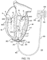
- FIG. 15 illustrates the system of FIG. 13 installed in the human heart in accordance with an exemplary embodiment of the disclosed subject matter.
- the atrioventricular pressure gradient is defined as the pressure difference (or a pressure differential) that produces or generates an energy and a force within the chambers of the heart that occurs naturally.
- the diastolic phase or diastole blood flows from the higher pressure atrium into the lower pressure ventricle causing the valve leaflets to open and thus allowing the blood to pass through the valve orifice.
- the pressure in the atrium is exceeded by the pressure in the ventricle thereby generating a pressure differential creating an energy and force which, in turn, pushes up and against the valve leaflets causing them to close and seal off the ventricle from the atrial chamber.
- the atrioventricular pressure gradient is the driving energy and force required to close the valve.
- the considerable forces of the atrioventricular pressure gradient are exerted on the closed atrial/ventricular valve. Very importantly, these forces are moved or transducted via the chordae tendinae and papillary muscles to and into the ventricular and septal walls.
- valvulo-ventricular wall interaction which provides and enables the healthy ventricle to maintain structural integrity to maintain healthy the elliptical geometry, and provides functional support for blood ejection.
- ventricular diastole the ventricular pressure rapidly decreases.
- the valve opens and blood rushes from the atrium into the ventricle through the valve orifice.
- the valve leaflets function as a vector or steering mechanism, directing ventricular flow at an angle or vector to create vortical initial spin as illustrated in FIG. 1 .
- Such angle or vector may be due to the asymmetry of the valve leaflets and/or to the different shapes and sizes of the leaflets. A vortex progression results.
- the initial hemodynamic spin begins with inflowing blood, powered by the atrioventricular pressure gradient.
- the gradient pressure engages that initial spin such that a vortex is created downstream.
- the resulting high velocity rotational flow now a reservoir of kinetic energy within the ventricle is believed significant to proper blood flow velocity and volume through and out of the heart.
- FIG. 2 illustrates that under certain conditions, such as a dilated cardiomyopathy (DCM) in which the heart becomes enlarged, the vortex fails to properly form, the elliptical shape is compromised or lost, the papillary muscles displaced resulting in the ventricle being unable to pump blood efficiently.
- DCM dilated cardiomyopathy
- a flow vectoring and vortical intracardiac velocity offsetting balloon is implanted in the ventricular space of the heart. It is connected to a tether or shaft anchored at the apex.
- the flow vectoring and vortical intracardiac velocity offsetting balloon is a fluid-filled adjustable balloon.
- the balloon may be contoured to the ventricular shape and may have a concave, convex, or other shape and sit within the ventricle either alone or as a component on the tether or shaft.
- the balloon is configured, shaped, sized, and fixed in place to raise the either the concave distal end or rounded distal end of said balloon into closer proximity of the atrio-ventricular valvular orifice, specifically the valvular leaflets, and the Left Ventricular Outflow Tract (LVOT) or Right Ventricular Outflow Tract (RVOT) in order to facilitate, enhance, and/or restore ventricular vortex and/or vortical hemodynamic flow.
- LVOT Left Ventricular Outflow Tract
- RVOT Right Ventricular Outflow Tract
- the hemodynamic velocity of inflowing blood may be altered by increasing or decreasing the distance of the balloon to the inflow tract of blood coming from the atrium into the ventricle by raising or lowering the ‘member’ or balloon.
- the implant device 100 includes a flow vectoring vortical intracardiac velocity offsetting balloon or ‘offsetting balloon’ which may be a fluid filled balloon 110 connected to a single or multi-lumen transducting conduit or shaft 200 (or force transducting tether).
- Balloon 110 is illustrated in a first configuration.
- the transducting shaft 200 is designed to be fixed to the apex A of the heart H by a therapeutic apical base plate assembly 300 . (Implantation of the device 100 in the heart H is illustrated herein below in FIGS. 12 and 15 .)
- the transducting conduit or shaft 200 is connected to a single or multi-lumen tube 400 after exiting the apex A.
- a single or multi-lumen tube 400 is connected to a control unit 600 .
- Control unit 600 adjusts the device performance via a fluid communicating system when connected to the single or multi-lumen tube 400 .
- the balloon 110 is fabricated with or covered, encapsulated, or patched with a material that inhibits thrombosis and/or promotes endothelialization and/or embolic free blood flow, e.g., but not limited to ePTFE, Dacron, or other materials.
- the material may be easily detachable from the balloon 110 .
- Balloon 110 includes a proximal portion 112 having a surface that is contoured to approximate the shape of the heart's ventricle and a distal portion 114 having a surface and may have a concave or recessed shape, including a raised rim portion 116 .
- the central portion of distal portion 114 defines position HI while in the first configuration.
- Balloon 110 is purposefully configured, shaped, sized, and fixed in place to raise the distal end 114 into closer proximity of the atrio-ventricular valvular apparatus and the atrial outflow tract/ventricular inflow tract in order to facilitate, enhance, and/or restore ventricular vortex and/or vortical hemodynamic flow by either accelerating or decelerating the outflow velocity of blood by occupying ventricular volume and shortening or lengthening the distance from the ventricular outflow tract.
- Hemodynamic upturn is created by the pressure gradient's driving force and shape as blood impacts and flows out of or off of of the vortical intracardiac velocity adjusting balloon.
- the location HI and the upturned portions 116 of distal portion 114 provide desirable flow characteristics, as discussed herein.
- balloon 110 is secured to the apex A of the patient's heart by therapeutic apical base plate assembly 300 including the base plate 302 and a ball jointed portion 304 .
- therapeutic apical base plate assembly 300 including the base plate 302 and a ball jointed portion 304 .
- round oval cutouts 306 are defined in the base plate 302 to allow fibrous tissue in-growth for long term security.
- control unit 600 which is implanted in the patient beneath the skin and capable of palpation by the surgeon, is provided to adjust the shape and size of the balloon 110 .
- control unit 600 is provided with three independent contained chambers 602 , 604 and 606 , each identifiable below the skin in some embodiments by palpable protrusions, one palpable protrusion for chamber one 602 , two palpable protrusions for chamber two 604 , and three palpable protrusions for chamber three 606 .
- control unit 600 ′ is illustrated in FIG.
- the control unit 600 is in fluid communication, via the tube 400 and shaft 200 , with the balloon 110 .
- tube 400 includes a plurality of lumens 402 , 404 , and 406 in respective fluid communication with chambers 602 , 604 and 606 .
- FIG. 9 tube 400 includes a plurality of lumens 402 , 404 , and 406 in respective fluid communication with chambers 602 , 604 and 606 .
- control unit 600 has a needle access pad of silicone and/or ePTFE, non-porous, or any semi-porous material, to allow fibrous tissue ingrowth (the body's method of preventing infection and facilitating hemostasis).
- fluid is introduced to or removed from chambers 602 , 604 and 606 to adjust the shape and/or location of balloon 110 .
- chamber 602 fluid is introduced or removed to increase or decrease the size of balloon 110 generally, and in particular the shape of the distal portion 114 for directing ventricular flow.
- the distal portion 114 defines a position HI with a relatively shallow concave depression when balloon 110 is in the first configuration.
- FIG 11 illustrates balloon 110 in a second configuration, in which distal portion 114 defines a position H 2 with a deep concave depression.
- the balloon 110 includes less fluid in the second configuration than in the first configuration.
- Other lumens may be used for hydraulic axial adjustment, communication of sensor data with the control unit, wiring, data storage, and power delivery, etc.
- the control unit 600 may contain power sources, sensoring control modules, the sensors themselves, and/or communications units.
- the proximal portion 112 of balloon 110 is contoured to the shape of the heart's ventricle VW, the distal portion 114 is concave and purposefully configured, shaped, sized, and fixed in place to raise the concave distal end 114 of balloon 110 into closer proximity of the atrio-ventricular valvular orifice AVVO, specifically the valvular leaflets VL, and the Left Ventricular Outflow Tract LVOT or Right Ventricular Outflow Tract RVOT in order to facilitate, enhance, and/or restore ventricular vortex and/or vortical hemodynamic flow by accelerating or decelerating the blood flow.
- the distal concave end 114 of the balloon 110 closest to the valvular orifice AVVO and in the path of the LVOT or RVOT, receives the ventricular inflow blood, changing its velocity with surface contact in the distal concave shape 114 , and proximity, in such a manner that the impact of said blood onto the distal end of the balloon 110 makes an upturn at rim portion 116 , at the proper distance from the leaflet, by impacting the concave shape, and the native hemodynamic outflow force being sufficient to initiate the hemodynamic upturn required, thereby allowing the native atrioventricular pressure gradient to properly effect and impact the formation of proper ventricular vortex/vortices.
- the proximity of the distal end 114 of the balloon 110 to the valvular orifice AVVO and the LVOT or RVOT is spatial and such that the velocity may be changed by surface contact and/or proximity and the hemodynamic upturn may occur.
- the proximal end 112 of the balloon 110 is configured to aid and/or restore the proper healthy elliptical shape of the intracardiac ventricle and acts a ‘mold’ to assist in positive geometric remodeling of the ventricular free wall VW and has an outer surface 112 in firm contact with the endocardium.
- the balloon is shape compliant to form to any shape within the atrium, the ventricle, or other existing spaces to include the apical endocardium or the left atrial appendage.
- the balloon is asymmetric or symmetric.
- the implant system includes sensoring nodes, transducers, or other diagnostic surveillance equipment that transmit information to an external receiving platform.
- FIGS. 13-15 illustrate another embodiment of the implant device 100 ′.
- Implant device 100 ′ is substantially identical to the device of implant device 100 , with the difference noted herein.
- implant device 100 ′ includes balloon 110 ′ having a convex proximal portion 112 ′ which conforms to the ventricular wall.
- Balloon 110 ′ further defines a convex 3 distal portion 3 a 114 ′.
- Balloon 110 ′ purposefully configured, shaped, sized, and fixed in place to raise the convex distal end 114 ′ of balloon 110 ′ into closer proximity of the atrio-ventricular valvular orifice AVVO, specifically the valvular leaflets VL, and the Left Ventricular Outflow Tract LVOT or Right Ventricular Outflow Tract RVOT in order to accelerate or decelerate hemodynamic velocity and volume, facilitate, enhance, and/or restore ventricular vortex and/or vortical hemodynamic flow.
- the balloon enhances, facilitates, and/or restores a diastolic vortex formation at a spatial point at which inflow velocity is changed and hemodynamic upturn is detected.
- the balloon provides a velocity change surface for diastolic blood inflow.
- the balloon provides a surface to change diastolic blood inflow vector.
- the balloon provides a distal diastolic vortex-facilitating surface.
- the balloon is adjustable in volume, size and shape at any time, to be constantly adjustable so that the distal diastolic vortex-facilitating surface may conform to patient specific anatomy and meet the specific individual need of each individual patient as hemodynamic flow conditions change or to assist in changing the flows.
- the balloon facilitates vortical blood formation during diastole.
- the balloon reduces hemodynamic ventricular volume and/or changes ventricular velocity and eliminates stagnant or pooled blood mainly in the apical regions of the ventricle.
- the adjustability of the balloon in volume, size and shape provides reduction of ventricular volume that conforms to patient-specific anatomy and meets the specific individual need of each individual patient.
- the shaft/conduit acts to transduct or transfer native cardiac energy and force to the ventricular free wall via the therapeutic apical anchoring base plate.
- the balloon acts to capture cardiac muscular and/or rotational and force and facilitates itself as a conduit for transfer of said energy and force to the therapeutic apical anchoring base plate via transduction utilizing the shaft it is connected to as the conduit.
- the balloon acts to increase or decrease the ventricular volume, being an attached device or component within the ventricle, as it inflates or deflates.
- the balloon acts to assist ventricular systole or diastole, being an attached device or component within the ventricle powered either by the native heart or an internal or external power source and/or sources as it inflates or deflates.
- the balloon acts to assist ventricular systole or diastole, being in fluid contact with the another balloon in different chamber of the heart using the pressure differential as a driving force or power source as it inflates or deflates.
- the balloon configuration can include a “balloon within a balloon,” which can be adjusted by changing the volume of the reservoir to move the shaft axially or longitudinally (up & down) in extension or retraction inside a human heart.
- the shape of the balloon can change hemodynamic velocity with contact, vector hemodynamic upturn, and engage the burst of pressure native to the atrioventricular pressure gradient to facilitate, enhance, and/or restore vortex, vortical flow, and/or ventricular flow in a ventricle in a human heart.
- the balloon on a shaft/conduit can be moved and/or fixed, spatially near a native or prosthetic structure, component, or the native ventricular outflow tract in, above, or below a valve orifice, to effect the velocity, vector, and/or hemodynamic upturn of flow off of the native or prosthetic valve leaflets to effect, enhance, and/or restore or repair vortex, vortical flow, and/or ventricular flow.
- the therapeutic apical base plate includes a ball-joint and can be implanted at a bias to move a structure, component, or device in, above, or below a valve orifice or between valve leaflet to effect, change, and/or repair native vortex and/or vortical and/or ventricular flow as deployed to assist a native or prosthetic structure, a native or prosthetic component, or prosthetic device.
Landscapes
- Health & Medical Sciences (AREA)
- Cardiology (AREA)
- Life Sciences & Earth Sciences (AREA)
- Engineering & Computer Science (AREA)
- Biomedical Technology (AREA)
- Public Health (AREA)
- Veterinary Medicine (AREA)
- Heart & Thoracic Surgery (AREA)
- Vascular Medicine (AREA)
- Animal Behavior & Ethology (AREA)
- General Health & Medical Sciences (AREA)
- Surgery (AREA)
- Transplantation (AREA)
- Oral & Maxillofacial Surgery (AREA)
- Reproductive Health (AREA)
- Nuclear Medicine, Radiotherapy & Molecular Imaging (AREA)
- Medical Informatics (AREA)
- Molecular Biology (AREA)
- Mechanical Engineering (AREA)
- Prostheses (AREA)
- External Artificial Organs (AREA)
Abstract
Description
Claims (19)
Priority Applications (1)
| Application Number | Priority Date | Filing Date | Title |
|---|---|---|---|
| US15/987,621 US10813761B2 (en) | 2017-05-23 | 2018-05-23 | Tethered implantable device having a vortical intracardiac velocity adjusting balloon |
Applications Claiming Priority (3)
| Application Number | Priority Date | Filing Date | Title |
|---|---|---|---|
| US201762509976P | 2017-05-23 | 2017-05-23 | |
| US201762509905P | 2017-05-23 | 2017-05-23 | |
| US15/987,621 US10813761B2 (en) | 2017-05-23 | 2018-05-23 | Tethered implantable device having a vortical intracardiac velocity adjusting balloon |
Publications (2)
| Publication Number | Publication Date |
|---|---|
| US20180338833A1 US20180338833A1 (en) | 2018-11-29 |
| US10813761B2 true US10813761B2 (en) | 2020-10-27 |
Family
ID=64395940
Family Applications (2)
| Application Number | Title | Priority Date | Filing Date |
|---|---|---|---|
| US15/987,621 Expired - Fee Related US10813761B2 (en) | 2017-05-23 | 2018-05-23 | Tethered implantable device having a vortical intracardiac velocity adjusting balloon |
| US15/987,430 Expired - Fee Related US10806581B2 (en) | 2017-05-23 | 2018-05-23 | Tethered implantable device having an apical base plate with a hydraulic intracardiac adjusting mechanism |
Family Applications After (1)
| Application Number | Title | Priority Date | Filing Date |
|---|---|---|---|
| US15/987,430 Expired - Fee Related US10806581B2 (en) | 2017-05-23 | 2018-05-23 | Tethered implantable device having an apical base plate with a hydraulic intracardiac adjusting mechanism |
Country Status (2)
| Country | Link |
|---|---|
| US (2) | US10813761B2 (en) |
| WO (2) | WO2018217919A1 (en) |
Cited By (2)
| Publication number | Priority date | Publication date | Assignee | Title |
|---|---|---|---|---|
| US11167122B2 (en) | 2018-03-05 | 2021-11-09 | Harmony Development Group, Inc. | Force transducting implant system for the mitigation of atrioventricular pressure gradient loss and the restoration of healthy ventricular geometry |
| US11883289B2 (en) | 2017-06-28 | 2024-01-30 | Harmony Development Group, Inc. | Force transducting inflatable implant system including a dual force annular transduction implant |
Families Citing this family (3)
| Publication number | Priority date | Publication date | Assignee | Title |
|---|---|---|---|---|
| US20200205738A1 (en) * | 2018-12-31 | 2020-07-02 | Biosense Webster (Israel) Ltd. | Occlusion detection via fluid dilution |
| NL2022660B1 (en) * | 2019-03-01 | 2020-09-15 | Stichting Katholieke Univ | Heart Assist Device |
| NL2028130B1 (en) | 2021-05-03 | 2022-11-10 | Cardiacbooster B V | Cardiac assist device with high frequency operation |
Citations (53)
| Publication number | Priority date | Publication date | Assignee | Title |
|---|---|---|---|---|
| US6406422B1 (en) * | 2000-03-02 | 2002-06-18 | Levram Medical Devices, Ltd. | Ventricular-assist method and apparatus |
| US20030032855A1 (en) | 1999-03-17 | 2003-02-13 | Mohsen Shahinpoor | Electrically-controllable multi-fingered resilient heart compression devices |
| US6827682B2 (en) | 1999-06-23 | 2004-12-07 | Mogens Bugge | Implantable device for utilization of the hydraulic energy of the heart |
| US20060058871A1 (en) | 2004-09-14 | 2006-03-16 | Edwards Lifesciences, Ag | Device and method for treatment of heart valve regurgitation |
| US20060241745A1 (en) * | 2005-04-21 | 2006-10-26 | Solem Jan O | Blood flow controlling apparatus |
| US20070198082A1 (en) | 2005-12-15 | 2007-08-23 | The Cleveland Clinic Foundation | Apparatus and method for treating a regurgitant valve |
| US20070265490A1 (en) * | 2006-02-27 | 2007-11-15 | Smith Robert M | Left ventricle assist device (lvad) |
| US20070270943A1 (en) | 2006-05-18 | 2007-11-22 | Jan Otto Solem | Device and method for improving heart valve function |
| US20070282157A1 (en) * | 2004-02-03 | 2007-12-06 | Atria Medical Inc. | Device And Method For Controlling In-Vivo Pressure |
| US20080064917A1 (en) | 2003-10-15 | 2008-03-13 | Eli Bar | Amplification-Based Cardiac Assist Device |
| US7435257B2 (en) | 2004-05-05 | 2008-10-14 | Direct Flow Medical, Inc. | Methods of cardiac valve replacement using nonstented prosthetic valve |
| US20080294251A1 (en) * | 2006-09-28 | 2008-11-27 | Bioventrix (A Chf Technologies' Company) | Location, time, and/or pressure determining devices, systems, and methods for deployment of lesion-excluding heart implants for treatment of cardiac heart failure and other disease states |
| US20080306328A1 (en) | 2007-06-07 | 2008-12-11 | Newcortec S.P.A. | Duct for ventricular-assistance device |
| US20090048668A1 (en) | 2008-06-13 | 2009-02-19 | Cardiosolutions, Inc. | System and Method for Implanting a Heart Implant |
| US20090131849A1 (en) | 2007-11-15 | 2009-05-21 | Cardiosolutions, Inc. | Heart regurgitation method and apparatus |
| US20090177028A1 (en) | 2008-01-04 | 2009-07-09 | Anthony John White | Non-blood contact cardiac compression device, for augmentation of cardiac function by timed cyclic tensioning of elastic cords in an epicardial location |
| US20090254195A1 (en) * | 1999-08-09 | 2009-10-08 | Alexander Khairkhahan | System for improving cardiac function by sealing a partitioning membrane within a ventricle |
| US7854762B2 (en) | 2005-05-20 | 2010-12-21 | Mayo Foundation For Medical Education And Research | Devices and methods for reducing cardiac valve regurgitation |
| US20110022164A1 (en) | 2004-12-15 | 2011-01-27 | Mednua Limited | Medical device for use in treatment of a valve |
| US20110196483A1 (en) * | 2008-10-10 | 2011-08-11 | Milux Holding Sa | Heart help device, system, and method |
| US20110224655A1 (en) | 2008-09-11 | 2011-09-15 | Asirvatham Samuel J | Central core multifunctional cardiac devices |
| US8092525B2 (en) | 2005-10-26 | 2012-01-10 | Cardiosolutions, Inc. | Heart valve implant |
| WO2012130052A1 (en) | 2011-03-25 | 2012-10-04 | Yang Bibo | Induction device for animal heart failure |
| US20130030519A1 (en) * | 2011-07-27 | 2013-01-31 | Edwards Lifesciences Corporation | Delivery systems for prosthetic heart valve |
| US20130172978A1 (en) | 2011-12-16 | 2013-07-04 | Tendyne Holdings Inc. | Tethers for Prosthetic Mitral Valve |
| US20130325110A1 (en) | 2012-05-16 | 2013-12-05 | Edwards Lifesciences Corporation | Systems and methods for placing a coapting member between valvular leaflets |
| US8778017B2 (en) | 2005-10-26 | 2014-07-15 | Cardiosolutions, Inc. | Safety for mitral valve implant |
| US20140277404A1 (en) * | 2013-03-15 | 2014-09-18 | Cardiosolutions, Inc. | Trans-apical implant systems, implants and methods |
| US20140336751A1 (en) | 2013-05-07 | 2014-11-13 | George Kramer | Inflatable Transcatheter Intracardiac Devices and Methods for Treating Incompetent Atrioventricular Valves |
| US20140371843A1 (en) | 2013-06-14 | 2014-12-18 | Cardiosolutions, Inc. | Mitral valve spacer and system and method for implanting the same |
| US20140371789A1 (en) * | 2012-02-29 | 2014-12-18 | Cardiapex Ltd. | Minimally invasive surgical techniques |
| US20150073539A1 (en) * | 2013-09-12 | 2015-03-12 | St. Jude Medical, Cardiology Division, Inc. | Alignment of an implantable medical device |
| US20150112429A1 (en) | 2011-01-28 | 2015-04-23 | Middle Peak Medical, Inc. | Coaptation enhancement implant, system, and method |
| US9050189B2 (en) | 2008-12-04 | 2015-06-09 | Georgia Tech Research Corporation | Method and apparatus for minimally invasive heart valve procedures |
| US9078660B2 (en) | 2000-08-09 | 2015-07-14 | Cardiokinetix, Inc. | Devices and methods for delivering an endocardial device |
| US20150223934A1 (en) * | 2014-02-11 | 2015-08-13 | Tendyne Holdings, Inc. | Adjustable tether and epicardial pad system for prosthetic heart valve |
| US20150245934A1 (en) * | 2012-09-27 | 2015-09-03 | Symetis Sa | Stent-valve, delivery apparatus, and stent-holder therefor |
| US20160089234A1 (en) | 2013-05-20 | 2016-03-31 | Twelve, Inc. | Implantable heart valve devices, mitral valve repair devices and associated systems and methods |
| US20160113765A1 (en) | 2014-10-23 | 2016-04-28 | Caisson Interventional, LLC | Systems and methods for heart valve therapy |
| US20160242909A1 (en) | 2005-02-07 | 2016-08-25 | Evalve, Inc. | Methods, systems and devices for cardiac valve repair |
| US20160317290A1 (en) * | 2012-09-06 | 2016-11-03 | Edwards Lifesciences Corporation | Heart valve sealing devices |
| US9486306B2 (en) | 2013-04-02 | 2016-11-08 | Tendyne Holdings, Inc. | Inflatable annular sealing device for prosthetic mitral valve |
| CN106214289A (en) | 2016-09-05 | 2016-12-14 | 广东脉搏医疗科技有限公司 | A kind of heart volume reduction implant |
| US20170000935A1 (en) | 2014-01-27 | 2017-01-05 | Children's Medical Center Corporation | Mechanical assist device |
| US20170136162A1 (en) * | 2014-06-30 | 2017-05-18 | Stichting Katholieke Universiteit | Heart support device |
| US20170172737A1 (en) | 2015-12-22 | 2017-06-22 | Nvt Ag | Prosthetic mitral valve coaptation enhancement device |
| US20180015141A1 (en) | 2015-01-26 | 2018-01-18 | Rhode Island Hospital, A Lifespan Partner | Use of PRG4 as an Anti-Inflammatory Agent |
| US20180185145A1 (en) | 2017-01-05 | 2018-07-05 | Harmony Development Group, Inc. | Inflatable device for improving physiological cardiac flow |
| WO2018129320A1 (en) | 2017-01-05 | 2018-07-12 | Harmony Development Group, Inc. | Expandable device for capturing regurgitant jet, volume, and force to effect ventricular function and remodeling |
| US20180318071A1 (en) | 2017-05-05 | 2018-11-08 | Lucian Lozonschi | Pressure differential actuated prosthetic medical device |
| US20180344461A1 (en) | 2017-05-31 | 2018-12-06 | Harmony Development Group, Inc. | Vortex transduction implant and inflatable sensor harboring platform |
| WO2019006152A1 (en) | 2017-06-28 | 2019-01-03 | Harmony Development Group, Inc. | A force transducting inflatable implant system including a dual force annular transduction implant |
| WO2019173385A1 (en) | 2018-03-05 | 2019-09-12 | Harmony Development Group, Inc. | A force transducting implant system for the mitigation of atrioventricular pressure gradient loss and the restoration of healthy ventricular geometry |
-
2018
- 2018-05-23 WO PCT/US2018/034174 patent/WO2018217919A1/en not_active Ceased
- 2018-05-23 US US15/987,621 patent/US10813761B2/en not_active Expired - Fee Related
- 2018-05-23 WO PCT/US2018/034177 patent/WO2018217921A1/en not_active Ceased
- 2018-05-23 US US15/987,430 patent/US10806581B2/en not_active Expired - Fee Related
Patent Citations (59)
| Publication number | Priority date | Publication date | Assignee | Title |
|---|---|---|---|---|
| US20030032855A1 (en) | 1999-03-17 | 2003-02-13 | Mohsen Shahinpoor | Electrically-controllable multi-fingered resilient heart compression devices |
| US6827682B2 (en) | 1999-06-23 | 2004-12-07 | Mogens Bugge | Implantable device for utilization of the hydraulic energy of the heart |
| US20090254195A1 (en) * | 1999-08-09 | 2009-10-08 | Alexander Khairkhahan | System for improving cardiac function by sealing a partitioning membrane within a ventricle |
| US6406422B1 (en) * | 2000-03-02 | 2002-06-18 | Levram Medical Devices, Ltd. | Ventricular-assist method and apparatus |
| US9078660B2 (en) | 2000-08-09 | 2015-07-14 | Cardiokinetix, Inc. | Devices and methods for delivering an endocardial device |
| US20080064917A1 (en) | 2003-10-15 | 2008-03-13 | Eli Bar | Amplification-Based Cardiac Assist Device |
| US20070282157A1 (en) * | 2004-02-03 | 2007-12-06 | Atria Medical Inc. | Device And Method For Controlling In-Vivo Pressure |
| US7435257B2 (en) | 2004-05-05 | 2008-10-14 | Direct Flow Medical, Inc. | Methods of cardiac valve replacement using nonstented prosthetic valve |
| US20060058871A1 (en) | 2004-09-14 | 2006-03-16 | Edwards Lifesciences, Ag | Device and method for treatment of heart valve regurgitation |
| US20110022164A1 (en) | 2004-12-15 | 2011-01-27 | Mednua Limited | Medical device for use in treatment of a valve |
| US20160242909A1 (en) | 2005-02-07 | 2016-08-25 | Evalve, Inc. | Methods, systems and devices for cardiac valve repair |
| US20140309732A1 (en) * | 2005-04-21 | 2014-10-16 | Edwards Lifesciences Corporation | Blood flow controlling apparatus |
| US9498330B2 (en) | 2005-04-21 | 2016-11-22 | Edwards Lifesciences Ag | Blood flow controlling apparatus |
| US20060241745A1 (en) * | 2005-04-21 | 2006-10-26 | Solem Jan O | Blood flow controlling apparatus |
| US7854762B2 (en) | 2005-05-20 | 2010-12-21 | Mayo Foundation For Medical Education And Research | Devices and methods for reducing cardiac valve regurgitation |
| US8092525B2 (en) | 2005-10-26 | 2012-01-10 | Cardiosolutions, Inc. | Heart valve implant |
| US8778017B2 (en) | 2005-10-26 | 2014-07-15 | Cardiosolutions, Inc. | Safety for mitral valve implant |
| US20070198082A1 (en) | 2005-12-15 | 2007-08-23 | The Cleveland Clinic Foundation | Apparatus and method for treating a regurgitant valve |
| US20070265490A1 (en) * | 2006-02-27 | 2007-11-15 | Smith Robert M | Left ventricle assist device (lvad) |
| US20070270943A1 (en) | 2006-05-18 | 2007-11-22 | Jan Otto Solem | Device and method for improving heart valve function |
| US20080294251A1 (en) * | 2006-09-28 | 2008-11-27 | Bioventrix (A Chf Technologies' Company) | Location, time, and/or pressure determining devices, systems, and methods for deployment of lesion-excluding heart implants for treatment of cardiac heart failure and other disease states |
| US20080306328A1 (en) | 2007-06-07 | 2008-12-11 | Newcortec S.P.A. | Duct for ventricular-assistance device |
| US20090131849A1 (en) | 2007-11-15 | 2009-05-21 | Cardiosolutions, Inc. | Heart regurgitation method and apparatus |
| US20090177028A1 (en) | 2008-01-04 | 2009-07-09 | Anthony John White | Non-blood contact cardiac compression device, for augmentation of cardiac function by timed cyclic tensioning of elastic cords in an epicardial location |
| US20090048668A1 (en) | 2008-06-13 | 2009-02-19 | Cardiosolutions, Inc. | System and Method for Implanting a Heart Implant |
| US20110224655A1 (en) | 2008-09-11 | 2011-09-15 | Asirvatham Samuel J | Central core multifunctional cardiac devices |
| US20110196483A1 (en) * | 2008-10-10 | 2011-08-11 | Milux Holding Sa | Heart help device, system, and method |
| US9050189B2 (en) | 2008-12-04 | 2015-06-09 | Georgia Tech Research Corporation | Method and apparatus for minimally invasive heart valve procedures |
| US20150112429A1 (en) | 2011-01-28 | 2015-04-23 | Middle Peak Medical, Inc. | Coaptation enhancement implant, system, and method |
| WO2012130052A1 (en) | 2011-03-25 | 2012-10-04 | Yang Bibo | Induction device for animal heart failure |
| US20130030519A1 (en) * | 2011-07-27 | 2013-01-31 | Edwards Lifesciences Corporation | Delivery systems for prosthetic heart valve |
| US20130172978A1 (en) | 2011-12-16 | 2013-07-04 | Tendyne Holdings Inc. | Tethers for Prosthetic Mitral Valve |
| US20140371789A1 (en) * | 2012-02-29 | 2014-12-18 | Cardiapex Ltd. | Minimally invasive surgical techniques |
| US20130325110A1 (en) | 2012-05-16 | 2013-12-05 | Edwards Lifesciences Corporation | Systems and methods for placing a coapting member between valvular leaflets |
| US20160317290A1 (en) * | 2012-09-06 | 2016-11-03 | Edwards Lifesciences Corporation | Heart valve sealing devices |
| US20150245934A1 (en) * | 2012-09-27 | 2015-09-03 | Symetis Sa | Stent-valve, delivery apparatus, and stent-holder therefor |
| US20160089237A1 (en) | 2013-03-15 | 2016-03-31 | Cardiosolutions, Inc. | Trans-apical implant systems, implants and methods |
| US20140277404A1 (en) * | 2013-03-15 | 2014-09-18 | Cardiosolutions, Inc. | Trans-apical implant systems, implants and methods |
| US9486306B2 (en) | 2013-04-02 | 2016-11-08 | Tendyne Holdings, Inc. | Inflatable annular sealing device for prosthetic mitral valve |
| US20140336751A1 (en) | 2013-05-07 | 2014-11-13 | George Kramer | Inflatable Transcatheter Intracardiac Devices and Methods for Treating Incompetent Atrioventricular Valves |
| US20160089234A1 (en) | 2013-05-20 | 2016-03-31 | Twelve, Inc. | Implantable heart valve devices, mitral valve repair devices and associated systems and methods |
| US20140371846A1 (en) | 2013-06-14 | 2014-12-18 | Cardiosolutions, Inc. | Mitral valve spacer and system and method for implanting the same |
| US20140371843A1 (en) | 2013-06-14 | 2014-12-18 | Cardiosolutions, Inc. | Mitral valve spacer and system and method for implanting the same |
| US20150073539A1 (en) * | 2013-09-12 | 2015-03-12 | St. Jude Medical, Cardiology Division, Inc. | Alignment of an implantable medical device |
| US20170000935A1 (en) | 2014-01-27 | 2017-01-05 | Children's Medical Center Corporation | Mechanical assist device |
| US20150223934A1 (en) * | 2014-02-11 | 2015-08-13 | Tendyne Holdings, Inc. | Adjustable tether and epicardial pad system for prosthetic heart valve |
| US20170136162A1 (en) * | 2014-06-30 | 2017-05-18 | Stichting Katholieke Universiteit | Heart support device |
| US20160113765A1 (en) | 2014-10-23 | 2016-04-28 | Caisson Interventional, LLC | Systems and methods for heart valve therapy |
| US20180015141A1 (en) | 2015-01-26 | 2018-01-18 | Rhode Island Hospital, A Lifespan Partner | Use of PRG4 as an Anti-Inflammatory Agent |
| US20170172737A1 (en) | 2015-12-22 | 2017-06-22 | Nvt Ag | Prosthetic mitral valve coaptation enhancement device |
| CN106214289A (en) | 2016-09-05 | 2016-12-14 | 广东脉搏医疗科技有限公司 | A kind of heart volume reduction implant |
| US20180185145A1 (en) | 2017-01-05 | 2018-07-05 | Harmony Development Group, Inc. | Inflatable device for improving physiological cardiac flow |
| WO2018129320A1 (en) | 2017-01-05 | 2018-07-12 | Harmony Development Group, Inc. | Expandable device for capturing regurgitant jet, volume, and force to effect ventricular function and remodeling |
| WO2018129312A1 (en) | 2017-01-05 | 2018-07-12 | Harmony Development Group, Inc. | Inflatable device for improving physiological cardiac flow |
| US20180318071A1 (en) | 2017-05-05 | 2018-11-08 | Lucian Lozonschi | Pressure differential actuated prosthetic medical device |
| US20180344461A1 (en) | 2017-05-31 | 2018-12-06 | Harmony Development Group, Inc. | Vortex transduction implant and inflatable sensor harboring platform |
| WO2018222894A1 (en) | 2017-05-31 | 2018-12-06 | Harmony Development Group, Inc. | Vortex transduction implant and inflatable sensor harboring platform |
| WO2019006152A1 (en) | 2017-06-28 | 2019-01-03 | Harmony Development Group, Inc. | A force transducting inflatable implant system including a dual force annular transduction implant |
| WO2019173385A1 (en) | 2018-03-05 | 2019-09-12 | Harmony Development Group, Inc. | A force transducting implant system for the mitigation of atrioventricular pressure gradient loss and the restoration of healthy ventricular geometry |
Non-Patent Citations (7)
| Title |
|---|
| International Search Report and Written Opinion for International Application No. PCT/US19/20816 dated Jul. 9, 2019. |
| International Search Report and Written Opinion for International Application No. PCT/US2018/012586 dated Mar. 20, 2018. |
| International Search Report and Written Opinion for International Application No. PCT/US2018/034174 dated Jul. 27, 2018. |
| International Search Report and Written Opinion for International Application No. PCT/US2018/034177 dated Jul. 20, 2018. |
| International Search Report and Written Opinion for International Application No. PCT/US2018/035427 dated Jul. 27, 2018. |
| International Search Report and Written Opinion for International Application No. PCT/US2018/040066 dated Sep. 12, 2018. |
| International Search Report and Written Opinion for International Application No. PCT/US2018/12578 dated Mar. 28, 2018. |
Cited By (3)
| Publication number | Priority date | Publication date | Assignee | Title |
|---|---|---|---|---|
| US11883289B2 (en) | 2017-06-28 | 2024-01-30 | Harmony Development Group, Inc. | Force transducting inflatable implant system including a dual force annular transduction implant |
| US11167122B2 (en) | 2018-03-05 | 2021-11-09 | Harmony Development Group, Inc. | Force transducting implant system for the mitigation of atrioventricular pressure gradient loss and the restoration of healthy ventricular geometry |
| US20220305251A1 (en) * | 2018-03-05 | 2022-09-29 | Harmony Development Group, Inc. | Force transducting implant system for the mitigation of atrioventricular pressure gradient loss and the restoration of healthy ventricular geometry |
Also Published As
| Publication number | Publication date |
|---|---|
| US20190060076A1 (en) | 2019-02-28 |
| WO2018217921A1 (en) | 2018-11-29 |
| US10806581B2 (en) | 2020-10-20 |
| US20180338833A1 (en) | 2018-11-29 |
| WO2018217919A1 (en) | 2018-11-29 |
Similar Documents
| Publication | Publication Date | Title |
|---|---|---|
| US10813761B2 (en) | Tethered implantable device having a vortical intracardiac velocity adjusting balloon | |
| US11167122B2 (en) | Force transducting implant system for the mitigation of atrioventricular pressure gradient loss and the restoration of healthy ventricular geometry | |
| US11883289B2 (en) | Force transducting inflatable implant system including a dual force annular transduction implant | |
| US10098992B2 (en) | Heart support device | |
| US7854762B2 (en) | Devices and methods for reducing cardiac valve regurgitation | |
| US10806571B2 (en) | Inflatable device for improving physiological cardiac flow | |
| US20200054449A1 (en) | Transcatheter mitral valve | |
| US20150100116A1 (en) | Implant and method for improving coaptation of an atrioventricular valve | |
| US20060129025A1 (en) | Systems for and methods of atrioventricular valve regurgitation and reversing ventricular remodeling | |
| CA3258684A1 (en) | Cardiovascular implant devices with flow conditioners to minimize disruption to and enhance cardiovascular hemodynamics | |
| JP2020503151A (en) | A scalable device for capturing ventricular jets, volume, and force to function and remodel the ventricle | |
| US20180344461A1 (en) | Vortex transduction implant and inflatable sensor harboring platform | |
| WO2025174843A1 (en) | Catheter treatment segment |
Legal Events
| Date | Code | Title | Description |
|---|---|---|---|
| FEPP | Fee payment procedure |
Free format text: ENTITY STATUS SET TO UNDISCOUNTED (ORIGINAL EVENT CODE: BIG.); ENTITY STATUS OF PATENT OWNER: SMALL ENTITY |
|
| AS | Assignment |
Owner name: HARMONY DEVELOPMENT GROUP, INC., NORTH CAROLINA Free format text: ASSIGNMENT OF ASSIGNORS INTEREST;ASSIGNORS:WILSON, JOHN;SEGUIN, CHRISTOPHER;REEL/FRAME:046005/0429 Effective date: 20170607 |
|
| FEPP | Fee payment procedure |
Free format text: ENTITY STATUS SET TO SMALL (ORIGINAL EVENT CODE: SMAL); ENTITY STATUS OF PATENT OWNER: SMALL ENTITY |
|
| STPP | Information on status: patent application and granting procedure in general |
Free format text: DOCKETED NEW CASE - READY FOR EXAMINATION |
|
| STPP | Information on status: patent application and granting procedure in general |
Free format text: NON FINAL ACTION MAILED |
|
| STPP | Information on status: patent application and granting procedure in general |
Free format text: FINAL REJECTION MAILED |
|
| STPP | Information on status: patent application and granting procedure in general |
Free format text: DOCKETED NEW CASE - READY FOR EXAMINATION |
|
| STPP | Information on status: patent application and granting procedure in general |
Free format text: NOTICE OF ALLOWANCE MAILED -- APPLICATION RECEIVED IN OFFICE OF PUBLICATIONS |
|
| STCF | Information on status: patent grant |
Free format text: PATENTED CASE |
|
| FEPP | Fee payment procedure |
Free format text: MAINTENANCE FEE REMINDER MAILED (ORIGINAL EVENT CODE: REM.); ENTITY STATUS OF PATENT OWNER: SMALL ENTITY |
|
| LAPS | Lapse for failure to pay maintenance fees |
Free format text: PATENT EXPIRED FOR FAILURE TO PAY MAINTENANCE FEES (ORIGINAL EVENT CODE: EXP.); ENTITY STATUS OF PATENT OWNER: SMALL ENTITY |
|
| STCH | Information on status: patent discontinuation |
Free format text: PATENT EXPIRED DUE TO NONPAYMENT OF MAINTENANCE FEES UNDER 37 CFR 1.362 |
|
| FP | Lapsed due to failure to pay maintenance fee |
Effective date: 20241027 |