US10809331B2 - Liquid crystal thermometer for MRI - Google Patents
Liquid crystal thermometer for MRI Download PDFInfo
- Publication number
- US10809331B2 US10809331B2 US15/912,420 US201815912420A US10809331B2 US 10809331 B2 US10809331 B2 US 10809331B2 US 201815912420 A US201815912420 A US 201815912420A US 10809331 B2 US10809331 B2 US 10809331B2
- Authority
- US
- United States
- Prior art keywords
- liquid crystal
- thermometer
- temperature
- crystal compositions
- mri
- Prior art date
- Legal status (The legal status is an assumption and is not a legal conclusion. Google has not performed a legal analysis and makes no representation as to the accuracy of the status listed.)
- Active, expires
Links
- 239000004973 liquid crystal related substance Substances 0.000 title claims abstract description 124
- 230000007704 transition Effects 0.000 claims abstract description 59
- 239000000203 mixture Substances 0.000 claims abstract description 58
- 238000000034 method Methods 0.000 claims abstract description 38
- 238000002595 magnetic resonance imaging Methods 0.000 claims description 56
- 239000000463 material Substances 0.000 claims description 19
- 239000007788 liquid Substances 0.000 claims description 17
- -1 polytetrafluoroethylene Polymers 0.000 claims description 12
- 239000005020 polyethylene terephthalate Substances 0.000 claims description 7
- 229920000139 polyethylene terephthalate Polymers 0.000 claims description 7
- LYCAIKOWRPUZTN-UHFFFAOYSA-N Ethylene glycol Chemical compound OCCO LYCAIKOWRPUZTN-UHFFFAOYSA-N 0.000 claims description 6
- 230000000295 complement effect Effects 0.000 claims description 5
- 229920002313 fluoropolymer Polymers 0.000 claims description 5
- 239000004811 fluoropolymer Substances 0.000 claims description 5
- 239000004986 Cholesteric liquid crystals (ChLC) Substances 0.000 claims description 4
- 239000004743 Polypropylene Substances 0.000 claims description 4
- 229920001903 high density polyethylene Polymers 0.000 claims description 4
- 239000004700 high-density polyethylene Substances 0.000 claims description 4
- 229920001684 low density polyethylene Polymers 0.000 claims description 4
- 239000004702 low-density polyethylene Substances 0.000 claims description 4
- 229920001155 polypropylene Polymers 0.000 claims description 4
- 238000004458 analytical method Methods 0.000 claims description 3
- NTXGQCSETZTARF-UHFFFAOYSA-N buta-1,3-diene;prop-2-enenitrile Chemical compound C=CC=C.C=CC#N NTXGQCSETZTARF-UHFFFAOYSA-N 0.000 claims description 3
- WGCNASOHLSPBMP-UHFFFAOYSA-N hydroxyacetaldehyde Natural products OCC=O WGCNASOHLSPBMP-UHFFFAOYSA-N 0.000 claims description 3
- 239000004417 polycarbonate Substances 0.000 claims description 3
- 229920000515 polycarbonate Polymers 0.000 claims description 3
- 239000004626 polylactic acid Substances 0.000 claims description 3
- 229920001343 polytetrafluoroethylene Polymers 0.000 claims description 3
- 239000004810 polytetrafluoroethylene Substances 0.000 claims description 3
- 229920002635 polyurethane Polymers 0.000 claims description 3
- 239000004814 polyurethane Substances 0.000 claims description 3
- 239000004800 polyvinyl chloride Substances 0.000 claims description 3
- 239000007787 solid Substances 0.000 claims description 3
- 238000012544 monitoring process Methods 0.000 claims description 2
- 229920000747 poly(lactic acid) Polymers 0.000 claims 2
- 229920000915 polyvinyl chloride Polymers 0.000 claims 2
- 238000005259 measurement Methods 0.000 abstract description 6
- 230000000712 assembly Effects 0.000 abstract description 3
- 238000000429 assembly Methods 0.000 abstract description 3
- 239000012071 phase Substances 0.000 description 71
- 230000005283 ground state Effects 0.000 description 11
- 239000000126 substance Substances 0.000 description 8
- 230000001419 dependent effect Effects 0.000 description 6
- 238000009529 body temperature measurement Methods 0.000 description 5
- 239000013078 crystal Substances 0.000 description 5
- 239000003292 glue Substances 0.000 description 5
- 229920003023 plastic Polymers 0.000 description 5
- 239000004033 plastic Substances 0.000 description 5
- 238000005481 NMR spectroscopy Methods 0.000 description 4
- 239000000853 adhesive Substances 0.000 description 4
- 230000001070 adhesive effect Effects 0.000 description 4
- 230000003098 cholesteric effect Effects 0.000 description 4
- 238000003384 imaging method Methods 0.000 description 4
- 229920002493 poly(chlorotrifluoroethylene) Polymers 0.000 description 4
- 239000005023 polychlorotrifluoroethylene (PCTFE) polymer Substances 0.000 description 4
- IMNFDUFMRHMDMM-UHFFFAOYSA-N N-Heptane Chemical compound CCCCCCC IMNFDUFMRHMDMM-UHFFFAOYSA-N 0.000 description 3
- 238000013461 design Methods 0.000 description 3
- 238000001514 detection method Methods 0.000 description 3
- 238000009792 diffusion process Methods 0.000 description 3
- 125000004435 hydrogen atom Chemical group [H]* 0.000 description 3
- 230000008569 process Effects 0.000 description 3
- CIWBSHSKHKDKBQ-JLAZNSOCSA-N Ascorbic acid Chemical compound OC[C@H](O)[C@H]1OC(=O)C(O)=C1O CIWBSHSKHKDKBQ-JLAZNSOCSA-N 0.000 description 2
- 206010028980 Neoplasm Diseases 0.000 description 2
- 239000004990 Smectic liquid crystal Substances 0.000 description 2
- 229930182558 Sterol Natural products 0.000 description 2
- YCIMNLLNPGFGHC-UHFFFAOYSA-N catechol Chemical compound OC1=CC=CC=C1O YCIMNLLNPGFGHC-UHFFFAOYSA-N 0.000 description 2
- 230000008859 change Effects 0.000 description 2
- 238000012512 characterization method Methods 0.000 description 2
- 238000011161 development Methods 0.000 description 2
- 238000011067 equilibration Methods 0.000 description 2
- 238000009472 formulation Methods 0.000 description 2
- 239000007791 liquid phase Substances 0.000 description 2
- 238000002156 mixing Methods 0.000 description 2
- 238000000655 nuclear magnetic resonance spectrum Methods 0.000 description 2
- 230000003647 oxidation Effects 0.000 description 2
- 238000007254 oxidation reaction Methods 0.000 description 2
- 238000007789 sealing Methods 0.000 description 2
- 238000001228 spectrum Methods 0.000 description 2
- 150000003432 sterols Chemical class 0.000 description 2
- 235000003702 sterols Nutrition 0.000 description 2
- 230000000007 visual effect Effects 0.000 description 2
- 238000012800 visualization Methods 0.000 description 2
- XLYOFNOQVPJJNP-UHFFFAOYSA-N water Substances O XLYOFNOQVPJJNP-UHFFFAOYSA-N 0.000 description 2
- 238000012935 Averaging Methods 0.000 description 1
- LFQSCWFLJHTTHZ-UHFFFAOYSA-N Ethanol Chemical compound CCO LFQSCWFLJHTTHZ-UHFFFAOYSA-N 0.000 description 1
- VGGSQFUCUMXWEO-UHFFFAOYSA-N Ethene Chemical compound C=C VGGSQFUCUMXWEO-UHFFFAOYSA-N 0.000 description 1
- PXGOKWXKJXAPGV-UHFFFAOYSA-N Fluorine Chemical compound FF PXGOKWXKJXAPGV-UHFFFAOYSA-N 0.000 description 1
- 206010020843 Hyperthermia Diseases 0.000 description 1
- 208000023178 Musculoskeletal disease Diseases 0.000 description 1
- 229940123973 Oxygen scavenger Drugs 0.000 description 1
- 239000004974 Thermotropic liquid crystal Substances 0.000 description 1
- 150000001298 alcohols Chemical class 0.000 description 1
- 235000010323 ascorbic acid Nutrition 0.000 description 1
- 239000011668 ascorbic acid Substances 0.000 description 1
- 229960005070 ascorbic acid Drugs 0.000 description 1
- 125000003289 ascorbyl group Chemical class [H]O[C@@]([H])(C([H])([H])O*)[C@@]1([H])OC(=O)C(O*)=C1O* 0.000 description 1
- QVGXLLKOCUKJST-UHFFFAOYSA-N atomic oxygen Chemical compound [O] QVGXLLKOCUKJST-UHFFFAOYSA-N 0.000 description 1
- 239000011324 bead Substances 0.000 description 1
- 201000011510 cancer Diseases 0.000 description 1
- 229910052799 carbon Inorganic materials 0.000 description 1
- 125000004432 carbon atom Chemical group C* 0.000 description 1
- 238000000576 coating method Methods 0.000 description 1
- 239000002131 composite material Substances 0.000 description 1
- 150000001875 compounds Chemical class 0.000 description 1
- 238000010276 construction Methods 0.000 description 1
- 239000012611 container material Substances 0.000 description 1
- 238000011109 contamination Methods 0.000 description 1
- 238000012937 correction Methods 0.000 description 1
- 230000002596 correlated effect Effects 0.000 description 1
- 238000005336 cracking Methods 0.000 description 1
- 238000003745 diagnosis Methods 0.000 description 1
- 238000002059 diagnostic imaging Methods 0.000 description 1
- 238000010586 diagram Methods 0.000 description 1
- ZBCBWPMODOFKDW-UHFFFAOYSA-N diethanolamine Chemical compound OCCNCCO ZBCBWPMODOFKDW-UHFFFAOYSA-N 0.000 description 1
- 238000005516 engineering process Methods 0.000 description 1
- 238000001704 evaporation Methods 0.000 description 1
- 230000008020 evaporation Effects 0.000 description 1
- 230000001747 exhibiting effect Effects 0.000 description 1
- 238000002474 experimental method Methods 0.000 description 1
- 239000000835 fiber Substances 0.000 description 1
- 238000007429 general method Methods 0.000 description 1
- 239000011521 glass Substances 0.000 description 1
- 150000002334 glycols Chemical class 0.000 description 1
- 230000036031 hyperthermia Effects 0.000 description 1
- 230000002977 hyperthermial effect Effects 0.000 description 1
- 238000001727 in vivo Methods 0.000 description 1
- 230000003993 interaction Effects 0.000 description 1
- 244000005700 microbiome Species 0.000 description 1
- 238000012986 modification Methods 0.000 description 1
- 230000004048 modification Effects 0.000 description 1
- 208000015122 neurodegenerative disease Diseases 0.000 description 1
- 230000000626 neurodegenerative effect Effects 0.000 description 1
- 239000003960 organic solvent Substances 0.000 description 1
- 230000001590 oxidative effect Effects 0.000 description 1
- 239000001301 oxygen Substances 0.000 description 1
- 229910052760 oxygen Inorganic materials 0.000 description 1
- 125000004430 oxygen atom Chemical group O* 0.000 description 1
- 230000010412 perfusion Effects 0.000 description 1
- 230000035699 permeability Effects 0.000 description 1
- 230000010363 phase shift Effects 0.000 description 1
- 229920003229 poly(methyl methacrylate) Polymers 0.000 description 1
- 229920005644 polyethylene terephthalate glycol copolymer Polymers 0.000 description 1
- 239000004926 polymethyl methacrylate Substances 0.000 description 1
- 238000003908 quality control method Methods 0.000 description 1
- 238000011160 research Methods 0.000 description 1
- 238000013214 routine measurement Methods 0.000 description 1
- 238000000926 separation method Methods 0.000 description 1
- 238000004904 shortening Methods 0.000 description 1
- 239000002904 solvent Substances 0.000 description 1
- 238000000527 sonication Methods 0.000 description 1
- 238000004611 spectroscopical analysis Methods 0.000 description 1
- 239000010421 standard material Substances 0.000 description 1
- 238000004861 thermometry Methods 0.000 description 1
- 231100000331 toxic Toxicity 0.000 description 1
- 230000002588 toxic effect Effects 0.000 description 1
- 238000011282 treatment Methods 0.000 description 1
- 238000011269 treatment regimen Methods 0.000 description 1
- 238000009849 vacuum degassing Methods 0.000 description 1
- 238000011179 visual inspection Methods 0.000 description 1
- 238000003466 welding Methods 0.000 description 1
Images


Classifications
-
- G—PHYSICS
- G01—MEASURING; TESTING
- G01K—MEASURING TEMPERATURE; MEASURING QUANTITY OF HEAT; THERMALLY-SENSITIVE ELEMENTS NOT OTHERWISE PROVIDED FOR
- G01K11/00—Measuring temperature based upon physical or chemical changes not covered by groups G01K3/00, G01K5/00, G01K7/00 or G01K9/00
- G01K11/12—Measuring temperature based upon physical or chemical changes not covered by groups G01K3/00, G01K5/00, G01K7/00 or G01K9/00 using changes in colour, translucency or reflectance
- G01K11/16—Measuring temperature based upon physical or chemical changes not covered by groups G01K3/00, G01K5/00, G01K7/00 or G01K9/00 using changes in colour, translucency or reflectance of organic materials
- G01K11/165—Measuring temperature based upon physical or chemical changes not covered by groups G01K3/00, G01K5/00, G01K7/00 or G01K9/00 using changes in colour, translucency or reflectance of organic materials of organic liquid crystals
-
- G—PHYSICS
- G01—MEASURING; TESTING
- G01K—MEASURING TEMPERATURE; MEASURING QUANTITY OF HEAT; THERMALLY-SENSITIVE ELEMENTS NOT OTHERWISE PROVIDED FOR
- G01K15/00—Testing or calibrating of thermometers
- G01K15/005—Calibration
-
- G—PHYSICS
- G01—MEASURING; TESTING
- G01N—INVESTIGATING OR ANALYSING MATERIALS BY DETERMINING THEIR CHEMICAL OR PHYSICAL PROPERTIES
- G01N24/00—Investigating or analyzing materials by the use of nuclear magnetic resonance, electron paramagnetic resonance or other spin effects
- G01N24/08—Investigating or analyzing materials by the use of nuclear magnetic resonance, electron paramagnetic resonance or other spin effects by using nuclear magnetic resonance
-
- G—PHYSICS
- G01—MEASURING; TESTING
- G01R—MEASURING ELECTRIC VARIABLES; MEASURING MAGNETIC VARIABLES
- G01R33/00—Arrangements or instruments for measuring magnetic variables
- G01R33/20—Arrangements or instruments for measuring magnetic variables involving magnetic resonance
- G01R33/28—Details of apparatus provided for in groups G01R33/44 - G01R33/64
-
- G—PHYSICS
- G01—MEASURING; TESTING
- G01R—MEASURING ELECTRIC VARIABLES; MEASURING MAGNETIC VARIABLES
- G01R33/00—Arrangements or instruments for measuring magnetic variables
- G01R33/20—Arrangements or instruments for measuring magnetic variables involving magnetic resonance
- G01R33/44—Arrangements or instruments for measuring magnetic variables involving magnetic resonance using nuclear magnetic resonance [NMR]
- G01R33/48—NMR imaging systems
- G01R33/4804—Spatially selective measurement of temperature or pH
-
- G—PHYSICS
- G01—MEASURING; TESTING
- G01R—MEASURING ELECTRIC VARIABLES; MEASURING MAGNETIC VARIABLES
- G01R33/00—Arrangements or instruments for measuring magnetic variables
- G01R33/20—Arrangements or instruments for measuring magnetic variables involving magnetic resonance
- G01R33/44—Arrangements or instruments for measuring magnetic variables involving magnetic resonance using nuclear magnetic resonance [NMR]
- G01R33/48—NMR imaging systems
- G01R33/54—Signal processing systems, e.g. using pulse sequences ; Generation or control of pulse sequences; Operator console
- G01R33/56—Image enhancement or correction, e.g. subtraction or averaging techniques, e.g. improvement of signal-to-noise ratio and resolution
- G01R33/5601—Image enhancement or correction, e.g. subtraction or averaging techniques, e.g. improvement of signal-to-noise ratio and resolution involving use of a contrast agent for contrast manipulation, e.g. a paramagnetic, super-paramagnetic, ferromagnetic or hyperpolarised contrast agent
-
- G—PHYSICS
- G01—MEASURING; TESTING
- G01R—MEASURING ELECTRIC VARIABLES; MEASURING MAGNETIC VARIABLES
- G01R33/00—Arrangements or instruments for measuring magnetic variables
- G01R33/20—Arrangements or instruments for measuring magnetic variables involving magnetic resonance
- G01R33/44—Arrangements or instruments for measuring magnetic variables involving magnetic resonance using nuclear magnetic resonance [NMR]
- G01R33/48—NMR imaging systems
- G01R33/58—Calibration of imaging systems, e.g. using test probes, Phantoms; Calibration objects or fiducial markers such as active or passive RF coils surrounding an MR active material
Definitions
- Magnetic resonance imaging is a powerful platform that enables non-invasive medical imaging with high resolution. MRI enables the diagnosis and assessment of various conditions such as cancer, neurodegenerative and musculoskeletal diseases. However, for MRI to be effective as a diagnostic tool, the measurement protocols must yield consistent results across different MRI systems. Differences in MRI hardware, software platforms and user implementation of imaging protocols produce variability in measurements across different systems or even at different time points for the same system. Such variability can lead to misdiagnosis or inconclusive findings.
- MRI phantoms which are objects that act as a surrogate for different body sections or tissue types.
- Such phantoms will typically contain solutions or materials that are ground truth standards having fixed and known values for various MRI parameters such as T1, T2, T2*, T1rho relaxation times; Proton Density; and Apparent Diffusion Coefficient.
- T1, T2, T2*, T1rho relaxation times; Proton Density; and Apparent Diffusion Coefficient The use of such standards enables systems to be characterized and standardized, and facilitates comparisons of images across different machines and time points.
- T1 and T2 relaxation time can be temperature dependent.
- Apparent Diffusion Coefficient is inherently temperature dependent. Therefore, variations in MRI bore temperatures, which can span from 15° C. to 25° C., will render the use of phantoms as ground truth standards irrelevant if not accurately corrected for temperature.
- Temperature measurement in MRI has been achieved using various methods and devices.
- digital, alcohol, or fiber optic thermometers are used to assess temperature. These methods are problematic for various reasons. Fiber-optic thermometers are expensive, require laborious set-up and tear down to implement.
- Other temperature sensors are invasive and require human interface with the phantom before and after the scan, and potentially compromise the MRI phantom integrity by introducing unwanted microorganisms into the phantom.
- NMR Nuclear Magnetic Resonance
- thermometers work well in an NMR environment where the main magnetic field is homogeneous, and other spatial dependencies can be ignored since the samples are small.
- variations in the magnetic field strength will introduce errors in the chemical shift based thermometer, prohibiting accurate temperature measurement if the thermometer is not reproducibly placed in the exact position, and if variations of the main magnetic field exist between scanners.
- liquid crystals have been proposed for monitoring temperature in an MRI context. Liquid crystals undergo temperature-specific phase changes that can be detected by MRI.
- Canadian Patent Number 1,288,812 entitled “Thermometry using phase transitions in encapsulated liquid crystals and magnetic resonance detection methods,” by McRae et al., it was proposed to use liquid crystals and their temperature-dependent phase shifts as an indicator of temperature, in the context of in vivo hyperthermia treatment of tumors. Temperatures in the range 42° C. to 45° C.
- McRae et al. While useful in the hyperthermic treatment regimen to which they were applied, are insufficient for calibration of phantoms. Few MRI scanners are equipped with the capability to do the spectroscopic analysis needed for McRae's technique, and obtaining MR spectra is a time consuming process that would not integrate well with the process used to characterize or standardize an MRI using a ground truth tissue mimicking standards. Furthermore, the signal obtained using McRae's methods is inadequate for the error assessment needs addressed herein due to the much smaller magnetic field used. Additionally, McRae's implementation required the use of the fluorine 19 to produce measurable signal; such material is expensive and toxic. Additionally, McRae's method requires the liquid crystals to be microencapsulated, making the transition temperature too broad for the accuracy needed for an MRI calibration thermometer
- novel implementations of liquid crystal temperature sensing techniques employ liquid crystals in an innovative way to achieve consistent temperature assessment and the accurate use of standards.
- the novel liquid crystal thermometers of the invention provide the art with an inexpensive and facile means of accurately measuring temperature when characterizing equipment against ground state standards.
- FIGS. 1A and 1B depict vessels of the invention used to encase liquid crystals.
- FIG. 1A is a drawing depicting the cylindrical vessel ( 101 ), with top protrusion ( 102 ) and bottom receiving indent ( 103 ).
- FIG. 1B is a cutaway view of the vessel, showing the top opening ( 104 ) sealed by an inserted hard plastic sphere, such as PMMA ( 105 ).
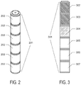
- FIG. 2 depicts a thermometer assembly of the invention ( 201 ) comprising six individual vessels ( 202 ) snapped together end to end.
- FIG. 3 represents a thermometer assembly of the invention which has been read by an appropriate MRI scan to determine whether liquid crystals are in the ordered or liquid phase.
- the liquid crystal MRI thermometers of the invention comprise a collection of different liquid crystal compositions, wherein each of the liquid crystal compositions has a unique phase transition temperature.
- a series of liquid crystal compositions having phase transitions spanning the range of typical MRI bore temperatures, e.g. 15-25° C., may be used.
- the assemblies of the invention are compatible with MRI phantoms and can be included therein. Temperature can be assessed quickly using T1-weighted, T2-weighted, or other scan protocols, wherein phase changes are readily assessed by distinct visual signals.
- FIG. 2 depicts an illustrative implementation of the invention comprising various elements:
- the devices and methods of the invention encompass the use of various liquid crystal compositions.
- the liquid crystal compositions will be selected and/or formulated such that each has a phase transition temperature at a selected value of interest.
- the liquid crystals may comprise any thermotropic liquid crystal composition known in the art, wherein an MRI-detectable phase transition occurs within a selected temperature range, for example, in the range of 15-25° C.
- sterol-based liquid crystals such as cholesteric liquid crystals may be used.
- Exemplary liquid crystals that may be used in the practice of the invention include those described in U.S. Pat. No. 5,422,033, entitled “Phase transition-type liquid crystal composition,” by Mochiziki et al.; U.S. Pat. No. 5,508,068, entitled “Cholesteric liquid crystal composition, color-forming liquid crystal composite product, method for protecting liquid crystal and color-forming liquid crystal picture laminated product,” by Nakano et al.; and in Brown and Wolken, Liquid Crystals and Biological Systems, Academic Press, NY, 1979.
- a phase transition temperature is a temperature point, or range of temperature values, wherein a volume of liquid crystals will transition between a liquid or isotropic phase and an ordered or crystalline phase such as the nematic, cholesteric, or smectic phase. At temperatures above the phase transition temperature, the composition will switch from an ordered (“crystalline”) phase to an isotropic (“liquid”) phase due to the kinetic energy/molecular motion of the molecules being too much to support the lower-energy ordered phase.
- An MRI-detectable phase transition means a phase transition that is detectable by a selected MRI scanning technique wherein an image is generated and wherein crystals in the liquid or isotropic phase generate a different signal, i.e. imaged differentially, from crystals in the ordered phase (e.g. nematic, cholesteric, or smectic).
- Crystals in the ordered phase e.g. nematic, cholesteric, or smectic.
- Liquid molecules in the crystalline state align with magnetic field and proton dipolar interactions cause rapid transitions that cause line broadening and shortening of the T2, and hence do not produce any MR signal.
- the isotropic phase they are fully liquid and contribute to the image signal intensity.
- the phase transition is MRI-detectable.
- the liquid crystal assemblages of the invention will comprise two or more separately contained aliquots of liquid crystals, wherein each separate aliquot comprises a unique composition having a unique phase transition temperature.
- the two or more aliquots of liquid crystals will define a temperature range, defined by the lowest transition phase temperature of the two or more liquid crystal compositions and the highest transition phase temperature of the two or more liquid crystal compositions, and encompassing intermediate phase transition temperature values, if any.
- the temperature range is a range typically found within the bore of an MRI system, which will typically encompass room temperatures, for example within the range of 15-25° C. It will generally be preferred that the liquid crystal compositions have phase transition temperatures separated at regular intervals, for example 0.1, 0.25, 0.5 or 1.0 degree Celsius increments.
- a series of liquid crystal compositions having phase transition temperatures separated by regular intervals can be formulated by mixing two miscible liquid crystal compositions having divergent phase transition temperatures in different proportions to arrive at different intermediate phase transition temperature values. For example, as described in Example 1, two liquid crystal compositions having phase transition temperatures of 11° C. and 42.5° C. were admixed in different proportions to create a series of seven compositions with phase transition temperatures in the range of 17-23° C.
- liquid crystal compositions can be used in the pure or native form, but can also be diluted in an organic solvent to achieve different temperature change characteristics, for example, as described in U.S. Pat. No. 5,508,068.
- Each aliquot of the two or more liquid crystal compositions will be enclosed in a separate container or a separate compartment of a body comprising multiple containers, separated from each other and from the atmosphere or surrounding liquid, to prevent loss, oxidation, evaporation of solvents, and contamination by microbes.
- enclosure or encasement of liquid crystals refers to containing or enclosing the materials in a macroscale vessel, and does not refer to microencapsulation techniques, such as those utilized in McRae, wherein microscopic aggregates of crystals were coated with biocompatible coatings.
- Oxidative attack on unsaturated bonds of the liquid crystals will broaden the temperature range of the phase transition by 0.1° C. to 1° C. or more.
- oxygen in the native liquid crystal chemicals is removed by either vacuum degassing, sonication, and/or passing the chemical stream through a nonmetallic oxygen scavenger such as ascorbic acid, ascorbate salts, or catechol prior to sealing it within a container or compartment.
- each of the two or more aliquots of liquid crystals are encased in a container.
- the container which contains each liquid crystal composition must be composed of a material that does not generate substantial MRI signal itself.
- Exemplary materials that may be utilized include polytetrafluoroethylene, e.g. TEFLONTM or other fluoropolymers; polycarbonate (PC); polypropylene (PP); polyethylene terephthalate (PET); glycol modified polyethylene terephthalate (PETG); polylactic acid (PLA); acrylonitrile butadiene (ABS); high and Low density polyethylene (HDPE/LDPE); polyvinylchloride (PVC); and polyurethane.
- TEFLONTM polytetrafluoroethylene
- PC polycarbonate
- PP polypropylene
- PET polyethylene terephthalate
- PET glycol modified polyethylene terephthalate
- PLA polylactic acid
- ABS acrylonitrile butadiene
- HDPE/LDPE
- polychlorotriflouroetheylene aka PCTFE, KEL-FTM, and NEOFLONTM.
- this material has particularly low perfusion and can advantageously be welded, which eliminates the need for glued seams or joints, increasing robustness.
- Flouroethylene based plastics are ideal, but also extremely difficult to glue due to the low surface energy of the material.
- the high thermal expansion coefficient of liquid crystals can produce large stresses on glued joints that can cause failure of the glued joints.
- an aliphatic amine such as n-Heptane adhesive may be used, for example LOCLITE 770 TM (Ellesworth Adhesives, Gemantown, Wis., USA).
- a critical factor in the design of the container is the liquid crystal aliquot size.
- An aliquot that is too large will act as a heat reservoir, and the temperature thereof will display hysteresis with the surrounding environment, i.e. it will not respond quickly to changes in the surrounding temperature and therefore cannot act as an accurate thermometer.
- a thermal time constant of 1 minute or less is desirable, to ensure rapid equilibration to the surrounding environment.
- an aliquot that is too small cannot generate sufficient signal to be visualized in an MRI scan.
- the inventors of the present disclosure have determined that a minimal aliquot size of 65 mm 3 liquid crystals and a maximum size of 3,500 mm 3 liquid crystals provides a sufficient signal while being sufficiently responsive to bore temperature. For example, aliquots of 120-700 mm 3 may be used.
- the containers of the invention will comprise a volume having a regular shape, such as a cube, cuboid, or cylinder.
- the container may comprise a regular cylinder of 7 mm inner diameter, and 8 mm height.
- the wall thickness of the vessel is an important consideration as well, as an overly thick encasement will slow the equilibration of the liquid crystals with the MRI bore or MRI phantom.
- a vessel wall thickness of 0.2-0.7 mm, for example, 0.5 mm may be used.
- the volume and container shapes are selected to ensure visualization of a cross section of the liquid crystals in one plane of the MRI system.
- the volume of material in the vessel should be at least one voxel in width, as determined by the settings and capabilities of the selected system.
- the volume may comprise at least two, three, or four voxel widths.
- the thermometer of the invention will comprise an assembly comprising multiple containers arranged in a linear or flat configuration, enabling imaging of the containers of the assembly in a single plane.
- the multiple containers will comprise aliquots of liquid crystals from the aforementioned series of liquid crystal solutions, for example 2, 3, 4, 5, 6, 7, 8, or more containers having liquid crystals with phase transition temperatures at regular increments, e.g. 0.1, 0.25, 0.5, or 1.0 degrees.
- each container comprises a pair of complementary interlocking elements that enable different containers to be snapped together in a linear configuration or other configuration.
- complementary elements may comprise, for example, tongue and groove elements, rib and debossed groove elements, or other complementary structures that interlock, or which can serve as attachment sites joined by adhesives or welding of the container material.
- the thermometer may comprise an assembly of interlocked or connected containers. For example, interlocking elements are depicted in FIG. 1A and an assembly comprising multiple interlocked or connected containers is depicted in FIG. 2 .
- the thermometer may comprise a housing or other body wherein multiple containers are held in place or otherwise contained in the housing or body.
- the thermometer assembly may comprise a linear configuration or any other configuration that allows for separate imaging of the multiple containers in the same plane.
- Thermometer assemblies can be designed for compatibility with MRI phantom components.
- the novel container of the invention comprises a cylindrical body which can be filled with a liquid crystal solution.
- the container of the invention comprises polychlorotriflouroetheylene.
- This fluoropolymer is chemically inert and has among the lowest permeability of water and other compounds.
- chemically inert plastics are difficult to glue, however PCTFE is somewhat unique as a fluoropolymer in that it can be welded, enabling construction of a vessel without glue joints that might interfere with MRI signals due to the chemical makeup of adhesives.
- the container of the invention comprises two pieces of PCTFE welded together to form a vessel having an opening, for example, a circular opening.
- the opening may comprise a proximal narrow section, an intermediate wider section, and distal narrow section.
- This opening enables the vessel to be filled to the top without any airspace, and it can then be sealed by forcing a hard plastic or glass sphere or bead into the opening, wherein the diameter of the sphere is slightly larger than that of the intermediate section of the opening.
- FIG. 1B A cross sectional diagram depicting an exemplary vessel and sealing sphere of the invention is depicted in FIG. 1B .
- the material of the container will comprise a material with sufficient flexibility or give to enable the sphere, under pressure to pass through the narrow section without cracking or breaking the material and become lodged and held in place in the intermediate wider space, creating an airtight and liquid-proof seal, and to accommodate the pressure forces exerted by the liquid when the sphere is forced into the locked position.
- an opening of sufficient width to inject the liquid crystals by syringe may be used, for example, to accommodate a 19 gauge needle may be used, for example, a diameter of 1 mm.
- thermometers of the invention may be placed within an MRI calibration phantom, as known in the art, in order to enable accurate characterization of the MRI system.
- the phantom may comprise a body, wherein the body contains an MRI thermometer of the invention and also contains one or more containers containing ground state standard materials.
- the MRI thermometer is immersed in a ground state material within the phantom.
- thermometers encompasses the afore-described thermometers.
- the scope of the invention further encompasses methods of using such thermometers to assess MRI bore and/or MRI phantom temperature.
- the general method encompasses the steps of:
- Temperature is assessed by determining the break point within a series of liquid crystal temperature standards, i.e. identifying a first liquid crystal composition in the series having the lowest phase transition temperature which is in the liquid state and a second liquid crystal composition in the series having the highest phase transition temperature which is in the solid state. Bore and/or phantom temperature can be determined as a value or range intermediate between the phase transition temperatures of the first and second compositions. Alternatively, identification of the liquid crystal aliquot having an intermediate phase (gray) can be used to determine the temperature value or range. For example, in a liquid crystal thermometer having aliquots with phase transition temperatures at 1° C. increments between 17° C. and 23° C., if the aliquot having a phase transitions temperature of 19° C.
- the bore temperature is assessed as being within the range of 19-20° C.
- thermometer is an assembly ( 301 ) comprising multiple vessels ( 302 , 303 , 304 , 305 , 306 , and 307 ), wherein each vessel contains a liquid crystal composition with a unique phase transition temperature, ordered from lowest phase transition temperature ( 302 ) to highest ( 307 ).
- the temperature was intermediate between the phase transition temperature of vessel 303 and that of 305 .
- these liquid crystals were in an isotropic state, yielding a bright signal.
- the temperature at the time of the scan was lower than the phase transition temperature of the liquid crystals in vessels 302 and 303 , and these liquid crystals were in an ordered state, yielding a dark signal.
- the temperature at the time of the scan was at about the phase transition temperature of the liquid crystals in vessel 304 , with these liquid crystals were in a mixed state with some ordered and some isotropic, yielding a gray signal.
- the scan may comprise any MRI imaging technique capable of producing differential signals by liquid crystals in the ordered and liquid states (and intermediate states, in some embodiments).
- exemplary scans include spin echo (SE), gradient echo (GRE) and spoiled gradient echo (SPGR).
- SE spin echo
- GRE gradient echo
- SPGR spoiled gradient echo
- the scan will be short, for example, being on the order of 0.25-2.0 minutes, for example, 1 minute or less. This insures that a snapshot of current temperature can be captured in the event of changing bore and/or phantom temperatures and that the temperature data acquisition does not significantly add to the duration of the scan time, and subsequently the quality control process used to evaluate and report the characteristics of the MRI machine.
- Exemplary scans include:
- the resulting scan is analyzed by visual inspection of the image, wherein the break point in the series of liquid crystal solutions is noted by an observer to determine temperature.
- the scan is analyzed by automated means, wherein an analysis algorithm or other technique is used to determine the break point between liquid and ordered crystals states in the series of liquid crystal solutions forming the thermometer.
- automated analysis techniques for determining light, dark, and/or gray can be readily implemented by one of skill in the art, for example, using computer aided detection algorithms.
- a single temperature scan may be performed or multiple temperature scans may be performed. For example, a temperature scan at the beginning of phantom assessment and at the end of phantom assessment may be performed and the average temperature of the two scans may be used to designate temperature of the ground state standards.
- the data acquired at an earlier timepoint would use the first temperature assessment and the data acquired at a timepoint closer to the end of the scan would use the last temperature assessment.
- the temperature would be measured at several time intervals to provide an adequate assessment of the temperature change over time.
- the scope of the invention comprises a method of characterizing an MRI system, comprising the steps of:
- a correction factor can be applied to MRI assessments of ground state standards based on the known relationship between ground state standard properties and temperature.
- a series of seven cholesteric (sterol based) liquid crystal formulations exhibiting a cholesteric to isotropic transition between 17° C. and 23° C. was formulated by mixing different proportions of two liquid crystal compositions.
- the liquid crystal compositions were product number GB310 (LCR Hallcrest, Glenview Ill., USA), having a phase transition temperature of 11° C. and GB320 (LCR Hallcrest, Glenview Ill., USA), having a phase transition temperature of 42.5° C.
- Table 1 lists the proportion of the two solutions in each mixture.
- a liquid crystal thermometer was constructed using multiple interlocking containers.
- Containers as depicted in FIG. 1A were constructed from PCTFE. Each container was filled with a different solution of liquid crystal compositions of the series of Example 1, by syringe, and was sealed by plugging the opening with hard plastic ball. The opening diameter was 0.035 inches+1-0.001 inches, and the sphere had a diameter of 0.0394 inches+/ ⁇ 0.002 inches.
- the interlocking containers were snapped together in order of increasing phase transition temperature. The resulting assembly is depicted in FIG. 2 .
- Example 2 The liquid crystal thermometer of Example 2 was placed in a Diffusion Standard (model number 128, QalibreMD (High Precision Devices), Boulder Colo., USA). The phantom was imaged on a 3 T clinical system (Siemens Prisma fit ) before and after routine measurements of ground state standards, with a scan duration of one hour. Using a 2D FLASH sequence, the temperature at initial scan was 19-19.7° C. and at the end of scanning the temperature had warmed to the 19.7-19.9° C., as determined by the light and dark break point between liquid crystal aliquots.
- a FLASH sequence is a fast low angle shot sequence, also known as a spoiled gradient-echo sequence using a flip angle of less than 90 degrees.
- a digital thermometer measured the temperature prior to scanning at 18.6 ⁇ 0.2° C., and post-scanning at 19.6 ⁇ 0.2° C. Differences between the initial temperature as measured by the digital thermometer and the liquid crystal thermometer are due to the 10 minute time difference between when the phantom temperature was measured with the digital thermometer and the first temperature scan was taken.
- thermometer Additional scans of the thermometer were performed in both pre-clinical (Agilent) and clinical (Siemens) systems at 3 T using various scan parameters:
Landscapes
- Physics & Mathematics (AREA)
- General Physics & Mathematics (AREA)
- High Energy & Nuclear Physics (AREA)
- Condensed Matter Physics & Semiconductors (AREA)
- Chemical & Material Sciences (AREA)
- Health & Medical Sciences (AREA)
- General Health & Medical Sciences (AREA)
- Crystallography & Structural Chemistry (AREA)
- Nuclear Medicine, Radiotherapy & Molecular Imaging (AREA)
- Radiology & Medical Imaging (AREA)
- Engineering & Computer Science (AREA)
- Signal Processing (AREA)
- Life Sciences & Earth Sciences (AREA)
- Analytical Chemistry (AREA)
- Biochemistry (AREA)
- Immunology (AREA)
- Pathology (AREA)
- Magnetic Resonance Imaging Apparatus (AREA)
Abstract
Description
-
- a plurality of containers;
- wherein each container contains a unique liquid crystal composition having a unique phase transition temperature;
- wherein the liquid crystal compositions have phase transition temperatures that span the selected range of interest;
- wherein liquid crystals in the isotropic, liquid phase and in the crystalline, ordered phase yield distinct signals in a selected MRI scan; and
- wherein the temperature of the MRI phantom can be determined by observing which compositions in the series are in the ordered phase, which are in the transition phase, and which are in the isotropic phase.
-
- acquiring an image of an MRI thermometer of the invention by a selected MRI scan technique;
- wherein the thermometer is in the MRI bore;
- by the acquired image, assessing the break point between a first liquid crystal composition being that with the lowest phase transition temperature which is in the liquid state and a second liquid crystal composition, being that with the highest phase transition temperature that is in the solid state;
- wherein the MRI bore temperature is determined as a being in a range intermediate between the phase transition temperatures of first and second liquid crystal compositions.
In the broadest implementation, the method encompasses performance of an MRI scan wherein the thermometer is imaged using MRI methodologies that result in differential signal of the liquid crystal aliquots when the liquid crystals are in an isotropic phase vs. an ordered phase. For example, the scan may result in an image wherein ordered crystals are dark (no or little signal) and isotropic, liquid crystals are imaged as bright (strong signal). In some implementations, an intermediate phase may also be detectable, the intermediate phase being indicative of a temperature at or near the phase transition temperature of the liquid crystals, for example, showing as gray.
-
- gradient echo, for example with parameters of: flip angle 70°, TR 200 ms, TE 5.00 ms, voxel size 0.55 mm2 by 3 mm slice thickness, acquisition time 51.2 s;
- spin-echo, for example with parameters of: flip angle 90°, TR 20.10 ms, TE 13.82 ms, voxel size 0.55 mm2 by 3 mm slice thickness, acquisition time 41.2 s;
- spoiled gradient echo (SPGR), for example with parameters of: flip angle 20°, TR 60.48 ms, TE 5.00 ms, voxel size 1.17 mm2 by 3 mm slice thickness, acquisition time 1.9 s; and
- spoiled gradient echo, for example with parameters of: flip angle 70°, TR 200 ms, TE 2.47 ms, voxel size 0.625 mm2 by 3 mm slice thickness, acquisition time less than sixty seconds.
The exemplary parameters presented above may be varied by one of skill in the art to attain suitable measurements that distinguish ordered and liquid crystal states for the selected liquid crystal compositions used in a particular thermometer. For example, the enumerated parameters of flip angle, repetition time (TR), echo time (TE), voxel size, and acquisition time listed above may be varied by up to 5%, up to 10%, or up to 25% in alternative implementations.
-
- determining MRI bore temperature or the temperature of ground state standards by means of a liquid crystal thermometer of the invention;
- measuring one or more temperature-dependent properties of the ground state standard; and
- correcting or adjusting the measure of the one or more temperature-dependent properties of the ground state standard based on the temperature measured by the liquid crystal thermometer of the invention.
| Transition | ||
| Temperature | % 11.5° C. LC | % 42.5° C. LC |
| 17° C.° | 83.6 | 16.4 |
| 18° C. | 80.6 | 19.4 |
| 19° C. | 77.6 | 22.4 |
| 20° C. | 74.6 | 25.4 |
| 21° C. | 71.6 | 28.4 |
| 22° C. | 68.7 | 31.3 |
| 23° C. | 65.7 | 34.3 |
-
- Pre-clinical gradient echo: flip angle 70°, TR 200 ms, TE 5.00 ms, 0.55 mm2 acquisition time 51.2 s;
- Pre-clinical spin-echo: flip angle 90°, TR 20.10 ms, TE 13.82 ms, 0.55 mm2 acquisition time 41.2 s;
- Pre-clinical spoiled gradient echo (SPGR): flip angle 20°, TR 60.48 ms, TE 5.00 ms, 1.17 mm2 acquisition time 1.9 s; and
- Clinical spoiled gradient echo: flip angle 70°, TR 200 ms, TE 2.47 ms, 0.625 mm2.
In each of the scans, the break point between liquid crystal aliquots was readily ascertained, both by manual visual examination of the scans and by computer aided detection algorithms, and measured temperatures were within 0.5° C. of bore temperatures measured by digital thermometer.
Claims (17)
Priority Applications (2)
| Application Number | Priority Date | Filing Date | Title |
|---|---|---|---|
| US15/912,420 US10809331B2 (en) | 2018-03-05 | 2018-03-05 | Liquid crystal thermometer for MRI |
| PCT/US2019/020622 WO2019173246A1 (en) | 2018-03-05 | 2019-03-04 | Liquid crystal thermometer for mri |
Applications Claiming Priority (1)
| Application Number | Priority Date | Filing Date | Title |
|---|---|---|---|
| US15/912,420 US10809331B2 (en) | 2018-03-05 | 2018-03-05 | Liquid crystal thermometer for MRI |
Publications (2)
| Publication Number | Publication Date |
|---|---|
| US20190271750A1 US20190271750A1 (en) | 2019-09-05 |
| US10809331B2 true US10809331B2 (en) | 2020-10-20 |
Family
ID=67767395
Family Applications (1)
| Application Number | Title | Priority Date | Filing Date |
|---|---|---|---|
| US15/912,420 Active 2038-06-15 US10809331B2 (en) | 2018-03-05 | 2018-03-05 | Liquid crystal thermometer for MRI |
Country Status (2)
| Country | Link |
|---|---|
| US (1) | US10809331B2 (en) |
| WO (1) | WO2019173246A1 (en) |
Families Citing this family (2)
| Publication number | Priority date | Publication date | Assignee | Title |
|---|---|---|---|---|
| US11733338B2 (en) * | 2018-06-16 | 2023-08-22 | Psychology Software Tools, Inc | MRI phantom including MRI compatible temperature measurement device and pressure expansion bladder device |
| GB2630125A (en) * | 2023-05-18 | 2024-11-20 | Perspectum Ltd | System and method for correcting the effect of temperature on magnetic resonance parameters |
Citations (12)
| Publication number | Priority date | Publication date | Assignee | Title |
|---|---|---|---|---|
| US4859360A (en) * | 1983-10-27 | 1989-08-22 | Biosynergy, Inc. | Cholesteric liquid crystal formulations and time/temperature monitoring means |
| CA1288812C (en) | 1988-09-30 | 1991-09-10 | Glenn A. Mcrae | Thermometry using phase transitions in encapsulated liquid crystals andmagnetic resonance detection methods |
| US5810888A (en) * | 1997-06-26 | 1998-09-22 | Massachusetts Institute Of Technology | Thermodynamic adaptive phased array system for activating thermosensitive liposomes in targeted drug delivery |
| US6280384B1 (en) * | 1998-04-16 | 2001-08-28 | Siemens Aktiengesellschaft | Intracorporeally introducible suspension of ferromagnetic particles and method using same for spatially resolved body temperature monitoring |
| US20040064031A1 (en) * | 2002-09-27 | 2004-04-01 | David Dean | Embedded thermal control system for high field MR scanners |
| US20050136002A1 (en) * | 1998-04-09 | 2005-06-23 | Fossheim Sigrid L. | Use of particulate contrast agents in diagnostic imaging for studying physiological paramaters |
| US20070197904A1 (en) * | 2002-09-11 | 2007-08-23 | Duke University | MRI imageable liposomes for the evaluation of treatment efficacy, thermal distribution, and demonstration of dose painting |
| US20090192383A1 (en) * | 2006-08-22 | 2009-07-30 | Koninklijke Philips Electronics N. V. | Method and device for obtaining information about a mammalian body |
| US20140005523A1 (en) * | 2011-03-17 | 2014-01-02 | Koninklijke Philips N.V. | Accelerated magnetic resonance thermometry |
| US20150247908A1 (en) * | 2012-09-17 | 2015-09-03 | The Johns Hopkins University | Non-Invasive Temperature Mapping Using Temperature-Responsive Water Saturation Shift Referencing (T-WASSR) MRI |
| US20150273245A1 (en) * | 2012-11-05 | 2015-10-01 | Koninklijke Philips N.V. | Medical apparatus for determining a maximum energy map |
| US20160133204A1 (en) * | 2014-11-11 | 2016-05-12 | Samsung Electronics Co., Ltd. | Method for controlling a display of an electronic device |
Family Cites Families (5)
| Publication number | Priority date | Publication date | Assignee | Title |
|---|---|---|---|---|
| JP3144045B2 (en) * | 1992-05-01 | 2001-03-07 | ダイキン工業株式会社 | Magnetic field measurement material |
| US6284078B1 (en) * | 1994-11-22 | 2001-09-04 | Medical Indicators, Inc. | Method for preparing an improved liquid crystal clinical thermometer |
| AU4722299A (en) * | 1998-06-26 | 2000-01-17 | Medical Indicators, Inc. | Liquid crystal thermometer |
| US9603546B2 (en) * | 2009-01-26 | 2017-03-28 | The United States Of America, As Represented By The Secretary, Department Of Health And Human Services | Phantom for diffusion MRI imaging |
| KR101431522B1 (en) * | 2013-05-10 | 2014-08-21 | 알피니언메디칼시스템 주식회사 | Reusable Phantom |
-
2018
- 2018-03-05 US US15/912,420 patent/US10809331B2/en active Active
-
2019
- 2019-03-04 WO PCT/US2019/020622 patent/WO2019173246A1/en not_active Ceased
Patent Citations (15)
| Publication number | Priority date | Publication date | Assignee | Title |
|---|---|---|---|---|
| US4859360A (en) * | 1983-10-27 | 1989-08-22 | Biosynergy, Inc. | Cholesteric liquid crystal formulations and time/temperature monitoring means |
| CA1288812C (en) | 1988-09-30 | 1991-09-10 | Glenn A. Mcrae | Thermometry using phase transitions in encapsulated liquid crystals andmagnetic resonance detection methods |
| US5810888A (en) * | 1997-06-26 | 1998-09-22 | Massachusetts Institute Of Technology | Thermodynamic adaptive phased array system for activating thermosensitive liposomes in targeted drug delivery |
| US20090191131A1 (en) * | 1998-04-09 | 2009-07-30 | Sigrid Lise Fossheim | Use of particulate contrast agents in diagnostic imaging for studying physiological paramaters |
| US20050136002A1 (en) * | 1998-04-09 | 2005-06-23 | Fossheim Sigrid L. | Use of particulate contrast agents in diagnostic imaging for studying physiological paramaters |
| US6280384B1 (en) * | 1998-04-16 | 2001-08-28 | Siemens Aktiengesellschaft | Intracorporeally introducible suspension of ferromagnetic particles and method using same for spatially resolved body temperature monitoring |
| US20070197904A1 (en) * | 2002-09-11 | 2007-08-23 | Duke University | MRI imageable liposomes for the evaluation of treatment efficacy, thermal distribution, and demonstration of dose painting |
| US20040064031A1 (en) * | 2002-09-27 | 2004-04-01 | David Dean | Embedded thermal control system for high field MR scanners |
| US20090192383A1 (en) * | 2006-08-22 | 2009-07-30 | Koninklijke Philips Electronics N. V. | Method and device for obtaining information about a mammalian body |
| US8335554B2 (en) * | 2006-08-22 | 2012-12-18 | Koninklijke Philips Electronics N.V. | Method and device for obtaining information about a mammalian body |
| US20140005523A1 (en) * | 2011-03-17 | 2014-01-02 | Koninklijke Philips N.V. | Accelerated magnetic resonance thermometry |
| US20150247908A1 (en) * | 2012-09-17 | 2015-09-03 | The Johns Hopkins University | Non-Invasive Temperature Mapping Using Temperature-Responsive Water Saturation Shift Referencing (T-WASSR) MRI |
| US20150273245A1 (en) * | 2012-11-05 | 2015-10-01 | Koninklijke Philips N.V. | Medical apparatus for determining a maximum energy map |
| US20160133204A1 (en) * | 2014-11-11 | 2016-05-12 | Samsung Electronics Co., Ltd. | Method for controlling a display of an electronic device |
| US9852705B2 (en) * | 2014-11-11 | 2017-12-26 | Samsung Electronics Co., Ltd | Method for controlling a display of an electronic device |
Also Published As
| Publication number | Publication date |
|---|---|
| US20190271750A1 (en) | 2019-09-05 |
| WO2019173246A1 (en) | 2019-09-12 |
Similar Documents
| Publication | Publication Date | Title |
|---|---|---|
| Liu et al. | High‐throughput screening of chemical exchange saturation transfer MR contrast agents | |
| Windschuh et al. | Correction of B1‐inhomogeneities for relaxation‐compensated CEST imaging at 7 T | |
| EP0122000B1 (en) | Method of detecting temperature in an object | |
| Captur et al. | A medical device-grade T1 and ECV phantom for global T1 mapping quality assurance—the T1 Mapping and ECV Standardization in cardiovascular magnetic resonance (T1MES) program | |
| Kıvrak et al. | Comparison of apparent diffusion coefficient values among different MRI platforms: a multicenter phantom study | |
| Raya et al. | T2 measurement in articular cartilage: impact of the fitting method on accuracy and precision at low SNR | |
| US10082553B2 (en) | MRI phantom, method for making same and acquiring an MRI image | |
| US10809331B2 (en) | Liquid crystal thermometer for MRI | |
| Raya et al. | Change of diffusion tensor imaging parameters in articular cartilage with progressive proteoglycan extraction | |
| WO2014043668A1 (en) | Non-invasive temperature mapping using temperature-responsive water saturation shift referencing (t-wassr) mri | |
| Brizi et al. | Bone volume–to–total volume ratio measured in trabecular bone by single‐sided NMR devices | |
| Gambarota et al. | Eliminating the blood‐flow confounding effect in intravoxel incoherent motion (IVIM) using the non‐negative least square analysis in liver | |
| Zhao et al. | Further exploration of MRI techniques for liver T1rho quantification | |
| Carr et al. | Determining the longitudinal accuracy and reproducibility of T1 and T2 in a 3T MRI scanner | |
| Liu et al. | UCEPR: Ultrafast localized CEST‐spectroscopy with PRESS in phantoms and in vivo | |
| Hayashi et al. | Multicenter, multivendor phantom study to validate proton density fat fraction and T2* values calculated using vendor-provided 6-point DIXON methods | |
| Müller-Lutz et al. | Improvement of water saturation shift referencing by sequence and analysis optimization to enhance chemical exchange saturation transfer imaging | |
| Knüttel et al. | Temperature measurements by nuclear magnetic resonance and its possible use as a means of in vivo noninvasive temperature measurement and for hyperthermia treatment assessment | |
| Oros-Peusquens et al. | Fast and accurate water content and T2⁎ mapping in brain tumours localised with FET-PET | |
| Andersen et al. | Precision, accuracy, and image plane uniformity in NMR relaxation time imaging on a 1.5 T whole-body MR imaging system | |
| Schindera et al. | Effect of echo time pair selection on quantitative analysis for adrenal tumor characterization with in-phase and opposed-phase MR imaging: initial experience | |
| JP7360825B2 (en) | Systems and methods for imaging tissue | |
| Wilde et al. | Assessment of quantitative magnetic resonance imaging metrics in the brain through the use of a novel phantom | |
| Yen et al. | T1 relaxation time of ISMRM/NIST T1 phantom spheres at 7 T | |
| Deichmann et al. | T1: Longitudinal relaxation time |
Legal Events
| Date | Code | Title | Description |
|---|---|---|---|
| FEPP | Fee payment procedure |
Free format text: ENTITY STATUS SET TO UNDISCOUNTED (ORIGINAL EVENT CODE: BIG.); ENTITY STATUS OF PATENT OWNER: SMALL ENTITY |
|
| AS | Assignment |
Owner name: QALIBREMD, INC, COLORADO Free format text: ASSIGNMENT OF ASSIGNORS INTEREST;ASSIGNORS:MIROWSKI, ELIZABETH;SNOW, MICHAEL;REEL/FRAME:045363/0278 Effective date: 20180322 |
|
| FEPP | Fee payment procedure |
Free format text: ENTITY STATUS SET TO SMALL (ORIGINAL EVENT CODE: SMAL); ENTITY STATUS OF PATENT OWNER: SMALL ENTITY |
|
| STPP | Information on status: patent application and granting procedure in general |
Free format text: NON FINAL ACTION MAILED |
|
| STPP | Information on status: patent application and granting procedure in general |
Free format text: NON FINAL ACTION MAILED |
|
| STPP | Information on status: patent application and granting procedure in general |
Free format text: NOTICE OF ALLOWANCE MAILED -- APPLICATION RECEIVED IN OFFICE OF PUBLICATIONS |
|
| STCF | Information on status: patent grant |
Free format text: PATENTED CASE |
|
| AS | Assignment |
Owner name: GOVERNMENT OF THE UNITED STATES OF AMERICA, AS REPRESENTED BY THE SECRETARY OF COMMERCE, MARYLAND Free format text: ASSIGNMENT OF ASSIGNORS INTEREST;ASSIGNOR:KEENAN, KATHRYN;REEL/FRAME:054287/0767 Effective date: 20200213 |
|
| FEPP | Fee payment procedure |
Free format text: MAINTENANCE FEE REMINDER MAILED (ORIGINAL EVENT CODE: REM.); ENTITY STATUS OF PATENT OWNER: SMALL ENTITY |
|
| FEPP | Fee payment procedure |
Free format text: SURCHARGE FOR LATE PAYMENT, SMALL ENTITY (ORIGINAL EVENT CODE: M2554); ENTITY STATUS OF PATENT OWNER: SMALL ENTITY |
|
| MAFP | Maintenance fee payment |
Free format text: PAYMENT OF MAINTENANCE FEE, 4TH YR, SMALL ENTITY (ORIGINAL EVENT CODE: M2551); ENTITY STATUS OF PATENT OWNER: SMALL ENTITY Year of fee payment: 4 |