US10808586B2 - Exhaust gas purification apparatus for an internal combustion engine - Google Patents
Exhaust gas purification apparatus for an internal combustion engine Download PDFInfo
- Publication number
- US10808586B2 US10808586B2 US16/210,012 US201816210012A US10808586B2 US 10808586 B2 US10808586 B2 US 10808586B2 US 201816210012 A US201816210012 A US 201816210012A US 10808586 B2 US10808586 B2 US 10808586B2
- Authority
- US
- United States
- Prior art keywords
- nox
- amount
- rich spike
- storage
- storage amount
- Prior art date
- Legal status (The legal status is an assumption and is not a legal conclusion. Google has not performed a legal analysis and makes no representation as to the accuracy of the status listed.)
- Expired - Fee Related
Links
Images


Classifications
-
- B—PERFORMING OPERATIONS; TRANSPORTING
- B01—PHYSICAL OR CHEMICAL PROCESSES OR APPARATUS IN GENERAL
- B01D—SEPARATION
- B01D53/00—Separation of gases or vapours; Recovering vapours of volatile solvents from gases; Chemical or biological purification of waste gases, e.g. engine exhaust gases, smoke, fumes, flue gases, aerosols
- B01D53/34—Chemical or biological purification of waste gases
- B01D53/92—Chemical or biological purification of waste gases of engine exhaust gases
- B01D53/94—Chemical or biological purification of waste gases of engine exhaust gases by catalytic processes
- B01D53/9404—Removing only nitrogen compounds
- B01D53/9409—Nitrogen oxides
- B01D53/9431—Processes characterised by a specific device
-
- B—PERFORMING OPERATIONS; TRANSPORTING
- B60—VEHICLES IN GENERAL
- B60W—CONJOINT CONTROL OF VEHICLE SUB-UNITS OF DIFFERENT TYPE OR DIFFERENT FUNCTION; CONTROL SYSTEMS SPECIALLY ADAPTED FOR HYBRID VEHICLES; ROAD VEHICLE DRIVE CONTROL SYSTEMS FOR PURPOSES NOT RELATED TO THE CONTROL OF A PARTICULAR SUB-UNIT
- B60W10/00—Conjoint control of vehicle sub-units of different type or different function
- B60W10/04—Conjoint control of vehicle sub-units of different type or different function including control of propulsion units
- B60W10/06—Conjoint control of vehicle sub-units of different type or different function including control of propulsion units including control of combustion engines
-
- F—MECHANICAL ENGINEERING; LIGHTING; HEATING; WEAPONS; BLASTING
- F01—MACHINES OR ENGINES IN GENERAL; ENGINE PLANTS IN GENERAL; STEAM ENGINES
- F01N—GAS-FLOW SILENCERS OR EXHAUST APPARATUS FOR MACHINES OR ENGINES IN GENERAL; GAS-FLOW SILENCERS OR EXHAUST APPARATUS FOR INTERNAL-COMBUSTION ENGINES
- F01N3/00—Exhaust or silencing apparatus having means for purifying, rendering innocuous, or otherwise treating exhaust
- F01N3/08—Exhaust or silencing apparatus having means for purifying, rendering innocuous, or otherwise treating exhaust for rendering innocuous
- F01N3/0807—Exhaust or silencing apparatus having means for purifying, rendering innocuous, or otherwise treating exhaust for rendering innocuous by using absorbents or adsorbents
- F01N3/0814—Exhaust or silencing apparatus having means for purifying, rendering innocuous, or otherwise treating exhaust for rendering innocuous by using absorbents or adsorbents combined with catalytic converters, e.g. NOx absorption/storage reduction catalysts
-
- F—MECHANICAL ENGINEERING; LIGHTING; HEATING; WEAPONS; BLASTING
- F01—MACHINES OR ENGINES IN GENERAL; ENGINE PLANTS IN GENERAL; STEAM ENGINES
- F01N—GAS-FLOW SILENCERS OR EXHAUST APPARATUS FOR MACHINES OR ENGINES IN GENERAL; GAS-FLOW SILENCERS OR EXHAUST APPARATUS FOR INTERNAL-COMBUSTION ENGINES
- F01N3/00—Exhaust or silencing apparatus having means for purifying, rendering innocuous, or otherwise treating exhaust
- F01N3/08—Exhaust or silencing apparatus having means for purifying, rendering innocuous, or otherwise treating exhaust for rendering innocuous
- F01N3/0807—Exhaust or silencing apparatus having means for purifying, rendering innocuous, or otherwise treating exhaust for rendering innocuous by using absorbents or adsorbents
- F01N3/0871—Exhaust or silencing apparatus having means for purifying, rendering innocuous, or otherwise treating exhaust for rendering innocuous by using absorbents or adsorbents using means for controlling, e.g. purging, the absorbents or adsorbents
-
- F—MECHANICAL ENGINEERING; LIGHTING; HEATING; WEAPONS; BLASTING
- F02—COMBUSTION ENGINES; HOT-GAS OR COMBUSTION-PRODUCT ENGINE PLANTS
- F02D—CONTROLLING COMBUSTION ENGINES
- F02D41/00—Electrical control of supply of combustible mixture or its constituents
- F02D41/009—Electrical control of supply of combustible mixture or its constituents using means for generating position or synchronisation signals
-
- F—MECHANICAL ENGINEERING; LIGHTING; HEATING; WEAPONS; BLASTING
- F02—COMBUSTION ENGINES; HOT-GAS OR COMBUSTION-PRODUCT ENGINE PLANTS
- F02D—CONTROLLING COMBUSTION ENGINES
- F02D41/00—Electrical control of supply of combustible mixture or its constituents
- F02D41/02—Circuit arrangements for generating control signals
- F02D41/021—Introducing corrections for particular conditions exterior to the engine
- F02D41/0235—Introducing corrections for particular conditions exterior to the engine in relation with the state of the exhaust gas treating apparatus
- F02D41/027—Introducing corrections for particular conditions exterior to the engine in relation with the state of the exhaust gas treating apparatus to purge or regenerate the exhaust gas treating apparatus
- F02D41/0275—Introducing corrections for particular conditions exterior to the engine in relation with the state of the exhaust gas treating apparatus to purge or regenerate the exhaust gas treating apparatus the exhaust gas treating apparatus being a NOx trap or adsorbent
-
- F—MECHANICAL ENGINEERING; LIGHTING; HEATING; WEAPONS; BLASTING
- F02—COMBUSTION ENGINES; HOT-GAS OR COMBUSTION-PRODUCT ENGINE PLANTS
- F02D—CONTROLLING COMBUSTION ENGINES
- F02D41/00—Electrical control of supply of combustible mixture or its constituents
- F02D41/02—Circuit arrangements for generating control signals
- F02D41/14—Introducing closed-loop corrections
- F02D41/1438—Introducing closed-loop corrections using means for determining characteristics of the combustion gases; Sensors therefor
- F02D41/1444—Introducing closed-loop corrections using means for determining characteristics of the combustion gases; Sensors therefor characterised by the characteristics of the combustion gases
- F02D41/1454—Introducing closed-loop corrections using means for determining characteristics of the combustion gases; Sensors therefor characterised by the characteristics of the combustion gases the characteristics being an oxygen content or concentration or the air-fuel ratio
-
- F—MECHANICAL ENGINEERING; LIGHTING; HEATING; WEAPONS; BLASTING
- F02—COMBUSTION ENGINES; HOT-GAS OR COMBUSTION-PRODUCT ENGINE PLANTS
- F02D—CONTROLLING COMBUSTION ENGINES
- F02D41/00—Electrical control of supply of combustible mixture or its constituents
- F02D41/02—Circuit arrangements for generating control signals
- F02D41/14—Introducing closed-loop corrections
- F02D41/1438—Introducing closed-loop corrections using means for determining characteristics of the combustion gases; Sensors therefor
- F02D41/1444—Introducing closed-loop corrections using means for determining characteristics of the combustion gases; Sensors therefor characterised by the characteristics of the combustion gases
- F02D41/146—Introducing closed-loop corrections using means for determining characteristics of the combustion gases; Sensors therefor characterised by the characteristics of the combustion gases the characteristics being an NOx content or concentration
- F02D41/1461—Introducing closed-loop corrections using means for determining characteristics of the combustion gases; Sensors therefor characterised by the characteristics of the combustion gases the characteristics being an NOx content or concentration of the exhaust gases emitted by the engine
-
- B—PERFORMING OPERATIONS; TRANSPORTING
- B01—PHYSICAL OR CHEMICAL PROCESSES OR APPARATUS IN GENERAL
- B01D—SEPARATION
- B01D2257/00—Components to be removed
- B01D2257/40—Nitrogen compounds
- B01D2257/404—Nitrogen oxides other than dinitrogen oxide
-
- B—PERFORMING OPERATIONS; TRANSPORTING
- B01—PHYSICAL OR CHEMICAL PROCESSES OR APPARATUS IN GENERAL
- B01D—SEPARATION
- B01D2258/00—Sources of waste gases
- B01D2258/01—Engine exhaust gases
- B01D2258/012—Diesel engines and lean burn gasoline engines
-
- B—PERFORMING OPERATIONS; TRANSPORTING
- B01—PHYSICAL OR CHEMICAL PROCESSES OR APPARATUS IN GENERAL
- B01D—SEPARATION
- B01D53/00—Separation of gases or vapours; Recovering vapours of volatile solvents from gases; Chemical or biological purification of waste gases, e.g. engine exhaust gases, smoke, fumes, flue gases, aerosols
- B01D53/34—Chemical or biological purification of waste gases
- B01D53/92—Chemical or biological purification of waste gases of engine exhaust gases
- B01D53/94—Chemical or biological purification of waste gases of engine exhaust gases by catalytic processes
- B01D53/9404—Removing only nitrogen compounds
- B01D53/9409—Nitrogen oxides
- B01D53/9413—Processes characterised by a specific catalyst
- B01D53/9422—Processes characterised by a specific catalyst for removing nitrogen oxides by NOx storage or reduction by cyclic switching between lean and rich exhaust gases (LNT, NSC, NSR)
-
- B—PERFORMING OPERATIONS; TRANSPORTING
- B01—PHYSICAL OR CHEMICAL PROCESSES OR APPARATUS IN GENERAL
- B01D—SEPARATION
- B01D53/00—Separation of gases or vapours; Recovering vapours of volatile solvents from gases; Chemical or biological purification of waste gases, e.g. engine exhaust gases, smoke, fumes, flue gases, aerosols
- B01D53/34—Chemical or biological purification of waste gases
- B01D53/92—Chemical or biological purification of waste gases of engine exhaust gases
- B01D53/94—Chemical or biological purification of waste gases of engine exhaust gases by catalytic processes
- B01D53/9495—Controlling the catalytic process
-
- F—MECHANICAL ENGINEERING; LIGHTING; HEATING; WEAPONS; BLASTING
- F01—MACHINES OR ENGINES IN GENERAL; ENGINE PLANTS IN GENERAL; STEAM ENGINES
- F01N—GAS-FLOW SILENCERS OR EXHAUST APPARATUS FOR MACHINES OR ENGINES IN GENERAL; GAS-FLOW SILENCERS OR EXHAUST APPARATUS FOR INTERNAL-COMBUSTION ENGINES
- F01N2250/00—Combinations of different methods of purification
- F01N2250/12—Combinations of different methods of purification absorption or adsorption, and catalytic conversion
-
- F—MECHANICAL ENGINEERING; LIGHTING; HEATING; WEAPONS; BLASTING
- F01—MACHINES OR ENGINES IN GENERAL; ENGINE PLANTS IN GENERAL; STEAM ENGINES
- F01N—GAS-FLOW SILENCERS OR EXHAUST APPARATUS FOR MACHINES OR ENGINES IN GENERAL; GAS-FLOW SILENCERS OR EXHAUST APPARATUS FOR INTERNAL-COMBUSTION ENGINES
- F01N2430/00—Influencing exhaust purification, e.g. starting of catalytic reaction, filter regeneration, or the like, by controlling engine operating characteristics
- F01N2430/06—Influencing exhaust purification, e.g. starting of catalytic reaction, filter regeneration, or the like, by controlling engine operating characteristics by varying fuel-air ratio, e.g. by enriching fuel-air mixture
-
- F—MECHANICAL ENGINEERING; LIGHTING; HEATING; WEAPONS; BLASTING
- F01—MACHINES OR ENGINES IN GENERAL; ENGINE PLANTS IN GENERAL; STEAM ENGINES
- F01N—GAS-FLOW SILENCERS OR EXHAUST APPARATUS FOR MACHINES OR ENGINES IN GENERAL; GAS-FLOW SILENCERS OR EXHAUST APPARATUS FOR INTERNAL-COMBUSTION ENGINES
- F01N2560/00—Exhaust systems with means for detecting or measuring exhaust gas components or characteristics
- F01N2560/02—Exhaust systems with means for detecting or measuring exhaust gas components or characteristics the means being an exhaust gas sensor
- F01N2560/025—Exhaust systems with means for detecting or measuring exhaust gas components or characteristics the means being an exhaust gas sensor for measuring or detecting O2, e.g. lambda sensors
-
- F—MECHANICAL ENGINEERING; LIGHTING; HEATING; WEAPONS; BLASTING
- F01—MACHINES OR ENGINES IN GENERAL; ENGINE PLANTS IN GENERAL; STEAM ENGINES
- F01N—GAS-FLOW SILENCERS OR EXHAUST APPARATUS FOR MACHINES OR ENGINES IN GENERAL; GAS-FLOW SILENCERS OR EXHAUST APPARATUS FOR INTERNAL-COMBUSTION ENGINES
- F01N2560/00—Exhaust systems with means for detecting or measuring exhaust gas components or characteristics
- F01N2560/02—Exhaust systems with means for detecting or measuring exhaust gas components or characteristics the means being an exhaust gas sensor
- F01N2560/026—Exhaust systems with means for detecting or measuring exhaust gas components or characteristics the means being an exhaust gas sensor for measuring or detecting NOx
-
- F—MECHANICAL ENGINEERING; LIGHTING; HEATING; WEAPONS; BLASTING
- F01—MACHINES OR ENGINES IN GENERAL; ENGINE PLANTS IN GENERAL; STEAM ENGINES
- F01N—GAS-FLOW SILENCERS OR EXHAUST APPARATUS FOR MACHINES OR ENGINES IN GENERAL; GAS-FLOW SILENCERS OR EXHAUST APPARATUS FOR INTERNAL-COMBUSTION ENGINES
- F01N2560/00—Exhaust systems with means for detecting or measuring exhaust gas components or characteristics
- F01N2560/06—Exhaust systems with means for detecting or measuring exhaust gas components or characteristics the means being a temperature sensor
-
- F—MECHANICAL ENGINEERING; LIGHTING; HEATING; WEAPONS; BLASTING
- F01—MACHINES OR ENGINES IN GENERAL; ENGINE PLANTS IN GENERAL; STEAM ENGINES
- F01N—GAS-FLOW SILENCERS OR EXHAUST APPARATUS FOR MACHINES OR ENGINES IN GENERAL; GAS-FLOW SILENCERS OR EXHAUST APPARATUS FOR INTERNAL-COMBUSTION ENGINES
- F01N2900/00—Details of electrical control or of the monitoring of the exhaust gas treating apparatus
- F01N2900/06—Parameters used for exhaust control or diagnosing
- F01N2900/14—Parameters used for exhaust control or diagnosing said parameters being related to the exhaust gas
- F01N2900/1402—Exhaust gas composition
-
- F—MECHANICAL ENGINEERING; LIGHTING; HEATING; WEAPONS; BLASTING
- F01—MACHINES OR ENGINES IN GENERAL; ENGINE PLANTS IN GENERAL; STEAM ENGINES
- F01N—GAS-FLOW SILENCERS OR EXHAUST APPARATUS FOR MACHINES OR ENGINES IN GENERAL; GAS-FLOW SILENCERS OR EXHAUST APPARATUS FOR INTERNAL-COMBUSTION ENGINES
- F01N2900/00—Details of electrical control or of the monitoring of the exhaust gas treating apparatus
- F01N2900/06—Parameters used for exhaust control or diagnosing
- F01N2900/16—Parameters used for exhaust control or diagnosing said parameters being related to the exhaust apparatus, e.g. particulate filter or catalyst
- F01N2900/1602—Temperature of exhaust gas apparatus
-
- F—MECHANICAL ENGINEERING; LIGHTING; HEATING; WEAPONS; BLASTING
- F01—MACHINES OR ENGINES IN GENERAL; ENGINE PLANTS IN GENERAL; STEAM ENGINES
- F01N—GAS-FLOW SILENCERS OR EXHAUST APPARATUS FOR MACHINES OR ENGINES IN GENERAL; GAS-FLOW SILENCERS OR EXHAUST APPARATUS FOR INTERNAL-COMBUSTION ENGINES
- F01N2900/00—Details of electrical control or of the monitoring of the exhaust gas treating apparatus
- F01N2900/06—Parameters used for exhaust control or diagnosing
- F01N2900/16—Parameters used for exhaust control or diagnosing said parameters being related to the exhaust apparatus, e.g. particulate filter or catalyst
- F01N2900/1614—NOx amount trapped in catalyst
-
- F—MECHANICAL ENGINEERING; LIGHTING; HEATING; WEAPONS; BLASTING
- F01—MACHINES OR ENGINES IN GENERAL; ENGINE PLANTS IN GENERAL; STEAM ENGINES
- F01N—GAS-FLOW SILENCERS OR EXHAUST APPARATUS FOR MACHINES OR ENGINES IN GENERAL; GAS-FLOW SILENCERS OR EXHAUST APPARATUS FOR INTERNAL-COMBUSTION ENGINES
- F01N2900/00—Details of electrical control or of the monitoring of the exhaust gas treating apparatus
- F01N2900/06—Parameters used for exhaust control or diagnosing
- F01N2900/16—Parameters used for exhaust control or diagnosing said parameters being related to the exhaust apparatus, e.g. particulate filter or catalyst
- F01N2900/1621—Catalyst conversion efficiency
-
- F—MECHANICAL ENGINEERING; LIGHTING; HEATING; WEAPONS; BLASTING
- F01—MACHINES OR ENGINES IN GENERAL; ENGINE PLANTS IN GENERAL; STEAM ENGINES
- F01N—GAS-FLOW SILENCERS OR EXHAUST APPARATUS FOR MACHINES OR ENGINES IN GENERAL; GAS-FLOW SILENCERS OR EXHAUST APPARATUS FOR INTERNAL-COMBUSTION ENGINES
- F01N3/00—Exhaust or silencing apparatus having means for purifying, rendering innocuous, or otherwise treating exhaust
- F01N3/08—Exhaust or silencing apparatus having means for purifying, rendering innocuous, or otherwise treating exhaust for rendering innocuous
- F01N3/0807—Exhaust or silencing apparatus having means for purifying, rendering innocuous, or otherwise treating exhaust for rendering innocuous by using absorbents or adsorbents
- F01N3/0828—Exhaust or silencing apparatus having means for purifying, rendering innocuous, or otherwise treating exhaust for rendering innocuous by using absorbents or adsorbents characterised by the absorbed or adsorbed substances
- F01N3/0835—Hydrocarbons
-
- F—MECHANICAL ENGINEERING; LIGHTING; HEATING; WEAPONS; BLASTING
- F01—MACHINES OR ENGINES IN GENERAL; ENGINE PLANTS IN GENERAL; STEAM ENGINES
- F01N—GAS-FLOW SILENCERS OR EXHAUST APPARATUS FOR MACHINES OR ENGINES IN GENERAL; GAS-FLOW SILENCERS OR EXHAUST APPARATUS FOR INTERNAL-COMBUSTION ENGINES
- F01N3/00—Exhaust or silencing apparatus having means for purifying, rendering innocuous, or otherwise treating exhaust
- F01N3/08—Exhaust or silencing apparatus having means for purifying, rendering innocuous, or otherwise treating exhaust for rendering innocuous
- F01N3/0807—Exhaust or silencing apparatus having means for purifying, rendering innocuous, or otherwise treating exhaust for rendering innocuous by using absorbents or adsorbents
- F01N3/0828—Exhaust or silencing apparatus having means for purifying, rendering innocuous, or otherwise treating exhaust for rendering innocuous by using absorbents or adsorbents characterised by the absorbed or adsorbed substances
- F01N3/0842—Nitrogen oxides
-
- F—MECHANICAL ENGINEERING; LIGHTING; HEATING; WEAPONS; BLASTING
- F01—MACHINES OR ENGINES IN GENERAL; ENGINE PLANTS IN GENERAL; STEAM ENGINES
- F01N—GAS-FLOW SILENCERS OR EXHAUST APPARATUS FOR MACHINES OR ENGINES IN GENERAL; GAS-FLOW SILENCERS OR EXHAUST APPARATUS FOR INTERNAL-COMBUSTION ENGINES
- F01N3/00—Exhaust or silencing apparatus having means for purifying, rendering innocuous, or otherwise treating exhaust
- F01N3/08—Exhaust or silencing apparatus having means for purifying, rendering innocuous, or otherwise treating exhaust for rendering innocuous
- F01N3/0807—Exhaust or silencing apparatus having means for purifying, rendering innocuous, or otherwise treating exhaust for rendering innocuous by using absorbents or adsorbents
- F01N3/0828—Exhaust or silencing apparatus having means for purifying, rendering innocuous, or otherwise treating exhaust for rendering innocuous by using absorbents or adsorbents characterised by the absorbed or adsorbed substances
- F01N3/0857—Carbon oxides
-
- F—MECHANICAL ENGINEERING; LIGHTING; HEATING; WEAPONS; BLASTING
- F02—COMBUSTION ENGINES; HOT-GAS OR COMBUSTION-PRODUCT ENGINE PLANTS
- F02D—CONTROLLING COMBUSTION ENGINES
- F02D2200/00—Input parameters for engine control
- F02D2200/02—Input parameters for engine control the parameters being related to the engine
- F02D2200/08—Exhaust gas treatment apparatus parameters
- F02D2200/0806—NOx storage amount, i.e. amount of NOx stored on NOx trap
-
- F—MECHANICAL ENGINEERING; LIGHTING; HEATING; WEAPONS; BLASTING
- F02—COMBUSTION ENGINES; HOT-GAS OR COMBUSTION-PRODUCT ENGINE PLANTS
- F02D—CONTROLLING COMBUSTION ENGINES
- F02D2200/00—Input parameters for engine control
- F02D2200/02—Input parameters for engine control the parameters being related to the engine
- F02D2200/08—Exhaust gas treatment apparatus parameters
- F02D2200/0808—NOx storage capacity, i.e. maximum amount of NOx that can be stored on NOx trap
-
- F—MECHANICAL ENGINEERING; LIGHTING; HEATING; WEAPONS; BLASTING
- F02—COMBUSTION ENGINES; HOT-GAS OR COMBUSTION-PRODUCT ENGINE PLANTS
- F02D—CONTROLLING COMBUSTION ENGINES
- F02D2200/00—Input parameters for engine control
- F02D2200/02—Input parameters for engine control the parameters being related to the engine
- F02D2200/08—Exhaust gas treatment apparatus parameters
- F02D2200/0811—NOx storage efficiency
Definitions
- the present disclosure relates to an exhaust gas purification apparatus for an internal combustion engine.
- an NOx storage reduction catalyst (hereinafter, sometimes also referred to as an “NSR catalyst”) is arranged as an exhaust gas purification catalyst in an exhaust passage of an internal combustion engine which performs lean burn operation in which an air fuel ratio of a mixture is adjusted to a lean air fuel ratio higher than a stoichiometric air fuel ratio.
- the NSR catalyst has a function to store NOx in exhaust gas when the air fuel ratio of its ambient atmosphere is a lean air fuel ratio, as well as to reduce the NOx thus stored when the air fuel ratio of the ambient atmosphere is a rich air fuel ratio lower than the stoichiometric air fuel ratio and when a reducing agent exists.
- the term “storage” is used as such including a mode of “adsorption”.
- the NOx stored in the NSR catalyst is reduced by the execution of rich spike which temporarily changes the air fuel ratio of the exhaust gas from a lean air fuel ratio higher than the stoichiometric air fuel ratio to a rich air fuel ratio lower than the stoichiometric air fuel ratio.
- patent literature 1 there is disclosed a technique in which rich spike is carried out when an amount of NOx trapped by an NOx trap catalyst reaches a predetermined amount.
- patent literature 2 there is disclosed a technology in which in an exhaust gas purification control device which carries out a rich spike operation in cases where an amount of NOx stored into an NSR catalyst exceeds a first threshold value, when the storage amount of NOx exceeds a second threshold value larger than the first threshold value, the rich spike operation is started at an air fuel ratio of the exhaust gas leaner than in the case where the storage amount of NOx is equal to or less than the second threshold value.
- Patent Literature 1 Japanese patent application laid-open publication No. 2005-163590
- Patent Literature 2 Japanese patent application laid-open publication No. 2016-186239
- the present disclosure has been made in view of the above-mentioned problems, and has for its object to provide a technique in which rich spike for reducing NOx stored in an NSR catalyst can be carried out in an efficient manner.
- the present disclosure is directed to an exhaust gas purification apparatus for an internal combustion engine which performs lean burn operation, the apparatus may comprising: an NOx storage reduction catalyst that is arranged in an exhaust passage of the internal combustion engine; and a controller comprising at least one processor is configured to carry out rich spike to temporarily change an air fuel ratio of exhaust gas flowing into the NOx storage reduction catalyst from a lean air fuel ratio higher than a stoichiometric air fuel ratio into a rich air fuel ratio lower than the stoichiometric air fuel ratio.
- NSR catalyst NOx storage reduction catalyst
- the NSR catalyst is constructed in such a manner that a precious metal catalyst such as Pt, etc., and an occlusion or storage material such as Ba, etc., are supported by a carrier such as alumina, etc. Then, the NOx, which has been made to react with oxygen by the precious metal catalyst for promoting the reaction of NOx and oxygen, is stored in the storage material.
- a precious metal catalyst such as Pt, etc.
- an occlusion or storage material such as Ba, etc.
- the NOx having flowed into the NSR catalyst tends to once turn into nitrites which are then stored in the storage material, and further, a part (or all) of the nitrites tends to turn into nitrates which are then stored in the storage material.
- the storage mode of the NOx already stored in the storage material may further change according to a change in the temperature of the NSR catalyst after the storage of the NOx.
- the storage mode of the NOx in the NSR catalyst changes according to the temperature of the NSR catalyst.
- the NOx stored in the NSR catalyst contains nitrates and nitrites.
- the nitrates stored in the storage material are stored in the storage material by a relatively weak adsorption force, but in contrast to this, the nitrates stored in the storage material are stored in the storage material by an adsorption force stronger than that by which the nitrites are stored in the storage material. Accordingly, when reducing the NOx stored in the NSR catalyst by the rich spike, the nitrates stored in the NSR catalyst become harder to be reduced than the nitrites stored in the NSR catalyst.
- a ratio of the amount of the nitrates stored in the NSR catalyst (hereinafter, sometimes referred to as a “storage amount of nitrates”) with respect to the amount of the NOx stored in the NSR catalyst (hereinafter, sometimes referred to as a “storage amount of NOx”) is defined as a nitrate ratio
- a ratio of the amount of NOx reduced by the execution of the rich spike with respect to the storage amount of NOx before the execution of the rich spike is defined as an NOx reduction efficiency
- the NOx reduction efficiency tends to become lower in comparison with the case where the rich spike is carried out in a state where the nitrate ratio is low. For that reason, there is a fear that the NOx stored in the NSR catalyst (in particular, the nitrates stored in the NSR catalyst) can not be reduced to a sufficient extent.
- the controller may calculate the storage amount of NOx and the storage amount of nitrates. Further, the controller may calculate the nitrate ratio based on the storage amount of NOx and the storage amount of nitrates. Then, the controller may control a timing at which the rich spike is carried out, based on the nitrate ratio.
- the controller can carry out the rich spike by advancing the timing, before the NOx reduction efficiency at the time of carrying out the rich spike decreases because the nitrate ratio becomes high.
- the rich spike can be carried out by advancing the timing more in the case where the nitrate ratio is high, than in the case where it is low. This makes it possible to carry out the rich spike in an efficient manner.
- the NOx flowing into the NSR catalyst and being able to be stored in the NSR catalyst i.e., most of the NOx discharged from the internal combustion engine can be stored in the NSR catalyst, as mentioned above, but in the case where the flow rate of exhaust gas is relatively large, etc., for example, a certain amount of the NOx discharged from the internal combustion engine may flow out from the NSR catalyst, without being stored in the NSR catalyst.
- the storage amount of NOx is the amount of nitrites and nitrates stored in the NSR catalyst.
- a part of this storage amount of NOx becomes the storage amount of nitrates.
- the storage amount of nitrates will change according to the storage amount of NOx.
- the NOx having flowed into the NSR catalyst is caused to react with oxygen, whereby the NOx can turn into nitrites, and further can turn into nitrates.
- the amount of nitrates to be produced may change according to an oxygen concentration of the exhaust gas flowing into the NSR catalyst. Accordingly, the storage amount of nitrates will change according to the oxygen concentration of the exhaust gas flowing into the NSR catalyst.
- the NOx having flowed into the NSR catalyst becomes easy to turn into nitrites and to be stored in the NSR catalyst, or it becomes easy to further turn from nitrites into nitrates and to be stored in the NSR catalyst, changes according to the temperature of the NSR catalyst. Accordingly, the storage amount of nitrates will change according to the temperature of the NSR catalyst.
- the storage amount of nitrates can be calculated based on the storage amount of NOx, the temperature of the NSR catalyst, and the oxygen concentration of the exhaust gas flowing into the NSR catalyst. Accordingly, the controller may calculate the storage amount of nitrates based on the storage amount of NOx, the temperature of the NOx storage reduction catalyst, and the oxygen concentration of the exhaust gas flowing into the NOx storage reduction catalyst. With this, the storage amount of nitrates can be calculated in an appropriate manner, thus making it possible to carry out the rich spike in an efficient manner.
- the rich spike has been carried out when the storage amount of NOx reaches a predetermined reference amount.
- the controller may carry out the rich spike, when the storage amount of NOx reaches the predetermined reference amount, and may further carry out the rich spike by changing the predetermined reference amount in such a manner that the predetermined reference amount becomes smaller in the case where the nitrate ratio is high than in the case where it is low.
- the execution timing of the rich spike is advanced more in the case where the nitrate ratio is high than in the case where it is low. This makes it possible to carry out the rich spike in an efficient manner.
- the controller may calculate the NOx reduction efficiency without depending on the execution of the rich spike, and the controller may calculate the NOx reduction efficiency based on the nitrate ratio, the temperature of the NOx storage reduction catalyst, and the storage amount of NOx. Then, the controller may calculate the NOx reduction efficiency in such a manner that the NOx reduction efficiency becomes lower as the nitrate ratio becomes higher, and that the NOx reduction efficiency becomes lower as the storage amount of NOx becomes larger, and that the NOx reduction efficiency becomes higher in the case where the temperature of the NOx storage reduction catalyst falls within a predetermined temperature range than in the case where the temperature does not fall within the range.
- the controller may carry out the rich spike, before the NOx reduction efficiency becomes lower than a predetermined reference efficiency.
- the nitrate ratio, the temperature of the NOx storage reduction catalyst and the storage amount of NOx each have a correlation with the NOx reduction efficiency. Specifically, the higher the nitrate ratio, the lower the NOx reduction efficiency becomes. In addition, the larger the storage amount of NOx, the lower the NOx reduction efficiency becomes. Moreover, the NOx reduction efficiency becomes higher in the case where the temperature of the NOx storage reduction catalyst falls within the predetermined temperature range than in the case where the temperature does not fall within the range. Accordingly, the NOx reduction efficiency in the case of carrying out the rich spike can be estimated based on these correlations, before the execution of the rich spike. Thus, the controller may calculate the NOx reduction efficiency based on these correlations, without depending on the execution of the rich spike.
- the NOx stored in the NSR catalyst becomes easier to be reduced by the rich spike, in comparison with the case when the NOx reduction efficiency is lower than the predetermined reference efficiency. In other words, it is possible to carry out the rich spike in an efficient manner.
- rich spike for reducing NOx stored in an NSR catalyst can be carried out in an efficient manner.
- FIG. 1 is a view indicating the schematic construction of an intake system and an exhaust system of an internal combustion engine.
- FIG. 2 is a view indicating how to cause a catalyst temperature to change over time when testing the influence of the catalyst temperature on the reduction of NOx in an NSR catalyst.
- FIG. 3 is a view indicating a correlation between a storage amount of NOx and an NOx reduction efficiency when tests in mode 1 through mode 4 indicated in FIG. 2 are carried out.
- FIG. 4A is a view for explaining a storage mode of NOx in the case where the temperature of the NSR catalyst is relatively low.
- FIG. 4B is a view for explaining a storage mode of NOx in the case where the temperature of the NSR catalyst is relatively high.
- FIG. 5 is a schematic diagram indicating an estimated NOx reduction mechanism in the NSR catalyst.
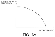
- FIG. 6A is a view indicating a correlation between a nitrate ratio and the NOx reduction efficiency.
- FIG. 6B is a view indicating a correlation between the catalyst temperature and the NOx reduction efficiency.
- FIG. 6C is a view indicating a correlation between the storage amount of NOx and the NOx reduction efficiency.
- FIG. 7 is a time chart indicating the changes over time of the storage amount of NOx, the catalyst temperature, the nitrate ratio, the NOx reduction efficiency, and an execution flag according to the first embodiment.
- FIG. 8 is a flow chart indicating a control flow according to the first embodiment.
- FIG. 9 is a view for explaining an example in which a reference amount is changed based on the nitrate ratio.
- FIG. 10 is a flow chart indicating a control flow according to a second embodiment.
- FIG. 11 is a time chart indicating the changes over time of a storage amount of NOx, a catalyst temperature, a nitrate ratio, a reference amount, and an execution flag according to the second embodiment.
- FIG. 1 is a view indicating the schematic construction of an intake system and an exhaust system of an internal combustion engine according to a first embodiment.
- the internal combustion engine 1 indicated in FIG. 1 is an internal combustion engine of compression ignition type (diesel engine).
- the present invention can also be applied to a lean burn internal combustion engine of spark ignition type which uses gasoline or the like as fuel.
- An intake passage 2 and an exhaust passage 3 are connected to the internal combustion engine 1 .
- An air flow meter 4 is arranged in the intake passage 2 .
- the air flow meter 4 serves to detect an amount of intake air sucked into the internal combustion engine 1 .
- a throttle valve 5 is arranged in the intake passage 2 at the downstream side of the air flow meter 4 .
- the throttle valve 5 serves to control the amount of intake air in the internal combustion engine 1 by changing the channel cross section of the intake passage 2 .
- an NOx storage reduction catalyst 6 (hereinafter, sometimes also referred to as an NSR catalyst 6 ) as an exhaust gas purification catalyst.
- an NOx selective catalytic reduction catalyst and/or a particulate filter in addition to the NSR catalyst 6 .
- a fuel addition valve 7 is arranged in the exhaust passage 3 at the upstream side of the NSR catalyst 6 . The fuel addition valve 7 serves to add fuel into exhaust gas. The fuel added from the fuel addition valve 7 is supplied to the NSR catalyst 6 along with the exhaust gas.
- an upstream side NOx sensor 13 and an air fuel ratio sensor 14 are arranged in the exhaust passage 3 at the downstream side of the fuel addition valve 7 and at the upstream side of the NSR catalyst 6 .
- the upstream side NOx sensor 13 detects the concentration of NOx in the exhaust gas flowing into the NSR catalyst 6 (hereinafter, sometimes also referred to as an “incoming exhaust gas”).
- the air fuel ratio sensor 14 detects the air fuel ratio of the incoming exhaust gas.
- a downstream side NOx sensor 15 and a temperature sensor 16 are arranged in the exhaust passage 3 at the downstream side of the NSR catalyst 6 .
- the downstream side NOx sensor 15 detects the concentration of NOx in the exhaust gas flowing out from the NSR catalyst 6 (hereinafter, sometimes also referred to as an “outgoing exhaust gas”).
- the temperature sensor 16 detects the temperature of the outgoing exhaust gas.
- an electronic control unit (ECU) 10 for controlling the internal combustion engine 1 .
- the air flow meter 4 , the upstream side NOx sensor 13 , the air fuel ratio sensor 14 , the downstream side NOx sensor 15 and the temperature sensor 16 are electrically connected to the ECU 10 .
- a crank angle sensor 11 and an accelerator opening sensor 12 are electrically connected to the ECU 10 .
- the crank angle sensor 11 outputs a signal having a correlation with a crank angle of the internal combustion engine 1 .
- the accelerator opening sensor 12 outputs a signal having a correlation with an opening degree of an accelerator of a vehicle on which the internal combustion engine 1 is mounted.
- the ECU 10 derives the rotation speed of the internal combustion engine 1 based on the output value of the crank angle sensor 11 . Also, the ECU 10 derives the engine load of the internal combustion engine 1 based on the output value of the accelerator opening sensor 12 .
- the ECU 10 estimates the flow rate of the exhaust gas (hereinafter, sometimes also referred to as an “exhaust gas flow rate”) based on the output value of the air flow meter 4 , and calculates the flow rate of NOx flowing into the NSR catalyst 6 (hereinafter, sometimes also referred to as an “NOx incoming flow rate”) based on the exhaust gas flow rate and the output value of the upstream side NOx sensor 13 , and calculates the flow rate of NOx flowing out from the NSR catalyst 6 (hereinafter, sometimes also referred to as an “NOx outgoing flow rate”) based on the exhaust gas flow rate and the output value of the downstream side NOx sensor 15 .
- the ECU 10 estimates the temperature of the NSR catalyst 6 (hereinafter, sometimes also referred to as a “catalyst temperature”) based on the output value of the temperature sensor 16 .
- fuel injection valves (illustration omitted) of the internal combustion engine 1 , the throttle valve 5 and the fuel addition valve 7 are electrically connected to the ECU 10 .
- these parts are controlled by the ECU 10 .
- the ECU 10 carries out processing to temporarily change the air fuel ratio of the exhaust gas flowing into the NSR catalyst 6 from a lean air fuel ratio higher than a stoichiometric air fuel ratio into a rich air fuel ratio lower than the stoichiometric air fuel ratio (hereinafter, sometimes also referred to as “rich spike processing”.
- the ECU 10 carries out the rich spike processing by adding fuel into the exhaust gas discharged from the internal combustion engine 1 with the use of the fuel addition valve 7 .
- the ECU 10 can carry out the rich spike processing by using well-known techniques.
- the ECU 10 may carry out the rich spike processing by forming a rich mixture in a cylinder using a fuel injection valve (illustration omitted) of the internal combustion engine 1 , and by combusting the rich mixture in the cylinder.
- a reducing agent such as HC, CO, etc.
- the NSR catalyst 6 When the rich spike processing is carried out, a reducing agent such as HC, CO, etc., is supplied to the NSR catalyst 6 . Then, the NOx stored in the NSR catalyst 6 (hereinafter, sometimes also referred to as the “stored NOx”) is reduced by this reducing agent.
- the stored NOx is mainly reduced by HC.
- the stored NOx is mainly reduced by CO and HC.
- FIG. 2 is a view indicating how to cause the catalyst temperature to change over time when testing the influence of the temperature of the NSR catalyst 6 (the catalyst temperature) on the reduction of NOx in the NSR catalyst 6 .
- the stored NOx is first purged at high temperature. That is, the stored NOx is released from the NSR catalyst 6 . Subsequently, NOx is supplied to the NSR catalyst 6 so that it is stored in the NSR catalyst 6 . Thereafter, the stored NOx is reduced by the reducing agent which is supplied to the NSR catalyst 6 . Then, the tests indicated in FIG. 2 have four test modes (i.e., from mode 1 to mode 4 ).
- the catalyst temperature at the time of storage is made at 200 degrees C.
- the catalyst temperature at the time of reduction is made at 300 degrees C.
- the catalyst temperatures at the time of storage and reduction are made at 300 degrees C.
- the catalyst temperatures at the time of storage and reduction are made at 200 degrees C.
- the catalyst temperature at the time of storage is made at 300 degrees C.
- the catalyst temperature at the time of reduction is made at 200 degrees C.
- FIG. 3 is a view indicating a correlation between an amount of the NOx stored in the NSR catalyst 6 (the stored NOx) (hereinafter, sometimes also referred to as a “storage amount of NOx”) at the time when the tests in the mode 1 through the mode 4 indicated in FIG. 2 , and a ratio of the amount of NOx reduced by the execution of the rich spike processing with respect to the storage amount of NOx before the execution of the rich spike processing (hereinafter, sometimes also referred to as an “NOx reduction efficiency”).
- the stored NOx the stored NOx
- NOx reduction efficiency a ratio of the amount of NOx reduced by the execution of the rich spike processing with respect to the storage amount of NOx before the execution of the rich spike processing
- the influence of the catalyst temperature at the time of reduction is grasped by making a comparison between the above-mentioned correlation in the mode 1 and the above-mentioned correlation in the mode 3 , or by making a comparison between the above-mentioned correlation in the mode 2 and the above-mentioned correlation in the mode 4 .
- the NOx reduction efficiency becomes higher in the case where the catalyst temperature at the time of reduction is high than in the case where it is low. Also, in FIG.
- the influence of the catalyst temperature at the time of storage is grasped by making a comparison between the above-mentioned correlation in the mode 1 and the above-mentioned correlation in the mode 2 , or by making a comparison between the above-mentioned correlation in the mode 3 and the above-mentioned correlation in the mode 4 . According to this, it is found that when the storage amount of NOx is the same, the NOx reduction efficiency becomes lower in the case where the catalyst temperature at the time of storage is high than in the case where it is low.
- FIG. 4A and FIG. 4B are views for explaining the storage mode of NOx in the NSR catalyst 6 .
- the storage mode of NOx will be explained by exemplifying a case where in the NSR catalyst 6 , there are used alumina (Al 2 O 3 ) as a carrier, and Pt as a precious metal catalyst, and Ba as an NOx storage material.
- NOx which has been caused to react with oxygen in the presence of Pt which promotes the reaction of NOx and oxygen, is stored in Ba.
- Pt which promotes the reaction of NOx and oxygen
- FIG. 4A is a view for explaining the storage mode of NOx in the case where the temperature of the NSR catalyst 6 is relatively low (e.g., from 250 degrees C. to 300 degrees C.).
- the NO having flowed into the NSR catalyst 6 is caused to react with oxygen in the presence of Pt.
- NO turns into nitrites (NO 2 ⁇ ).
- the nitrites are stored into Ba by a relatively weak adsorption force.
- FIG. 4B is a view for explaining the storage mode of NOx in the case where the temperature of the NSR catalyst 6 is relatively high (e.g., from 350 degrees C. to 400 degrees C.).
- the NO having flowed into the NSR catalyst 6 is caused to react with oxygen in the presence of Pt thereby to generate nitrites (NO 2 ⁇ ), as a result of which the nitrites thus generated are stored into Ba by a relatively weak adsorption force.
- the storage mode of the NOx already stored in Ba can further change according to a change in the temperature of the NSR catalyst 6 after the storage of the NOx.
- the storage mode of the NOx in the NSR catalyst 6 changes according to the temperature of the NSR catalyst 6 .
- the stored NOx (the NOx stored in the NSR catalyst 6 ) contains nitrates and nitrites as referred to above. Accordingly, the storage amount of NOx is the amount of nitrites and nitrates stored in the NSR catalyst 6 .
- nitrites and nitrates are stored in the storage material Ba.
- the nitrites are reduced to NO, as indicated in the middle row of FIG. 5 .
- a part of the nitrates is reduced to nitrites.
- the adsorption force between the nitrites and Ba is relatively weak, so the nitrites stored in Ba can be reduced easily.
- the adsorption force between the nitrates and Ba is relatively strong, so the nitrates stored in Ba becomes hard to be reduced.
- the nitrites having been stored in Ba before the execution of the rich spike processing are reduced up to N 2 to desorb from the NSR catalyst 6 , but in contrast to this, the nitrates having been stored in Ba before the execution of the rich spike processing may continue to be stored in the NSR catalyst 6 , without being reduced at all or without being reduced up to N 2 even if reduced.
- the NOx reduction efficiency may change resulting from the storage mode of the NOx in the NSR catalyst 6 .
- the amount of the nitrates stored in the NSR catalyst 6 is defined as a “storage amount of nitrates”.
- the ratio of the storage amount of nitrates with respect to the storage amount of NOx is defined as a nitrate ratio. In that case, there is a tendency that the higher the nitrate ratio, the lower the NOx reduction efficiency becomes.
- the NOx reduction efficiency tends to become lower in comparison with the case where the rich spike processing is carried out in a state where the nitrate ratio is low. For that reason, there is a fear that the stored NOx can not be reduced to a sufficient extent.
- the ECU 10 calculates the above-mentioned nitrate ratio. Then, the ECU 10 controls a timing at which the rich spike processing is carried out, based on the nitrate ratio thus calculated.
- the ECU 10 estimates the NOx reduction efficiency in the case of carrying out the rich spike before the execution of the rich spike processing. In other words, the ECU 10 calculates the NOx reduction efficiency without depending on the execution of the rich spike processing. Then, the ECU 10 actually carries out the rich spike processing, before the NOx reduction efficiency calculated without depending on the execution of the rich spike processing becomes lower than a reference efficiency. This makes it possible to carry out the rich spike processing in an efficient manner.
- the NOx reduction efficiency has a correlation with each of the nitrate ratio, the temperature of the NOx storage reduction catalyst and the storage amount of NOx. Accordingly, the ECU 10 can calculate the NOx reduction efficiency based on the values of these parameters and the correlations between the parameters and the NOx reduction efficiency.
- FIG. 6A is a view indicating the correlation between the nitrate ratio and the NOx reduction efficiency. As indicated in FIG. 6A , the higher the nitrate ratio, the lower the NOx reduction efficiency becomes.
- FIG. 6B is a view indicating the correlation between the catalyst temperature and the NOx reduction efficiency. As indicated in FIG. 6B , the NOx reduction efficiency becomes higher in the case where the catalyst temperature falls within a predetermined temperature range (e.g., a range which is equal to or higher than Tcth 1 , and is equal to or lower than Tcth 2 , as indicated in FIG.
- a predetermined temperature range e.g., a range which is equal to or higher than Tcth 1 , and is equal to or lower than Tcth 2 , as indicated in FIG.
- FIG. 6C is a view indicating the correlation between the storage amount of NOx and the NOx reduction efficiency. As indicated in FIG. 6C , the larger the storage amount of NOx, the lower the NOx reduction efficiency becomes. In particular, when the storage amount of NOx increases more than a certain amount (e.g., NOxth 1 indicated in FIG. 6C ), the NOx reduction efficiency decreases to a large extent.
- a certain amount e.g., NOxth 1 indicated in FIG. 6C
- FIG. 7 is the time chart indicating the changes over time of the storage amount of NOx NOxsum, the catalyst temperature Tc, the nitrate ratio NO3rate, the NOx reduction efficiency n and an execution flag fl which is a flag indicating whether the rich spike processing is carried out or not.
- the above-mentioned changes over time in the case where control based on the present disclosure is carried out are represented by solid lines. Also, in FIG.
- the change over time of the storage amount of NOx in the case where control based on the conventional technique is carried out is indicated as a reference by a broken line.
- the NOx reduction efficiency decreases in a process in which NOx is stored into the NSR catalyst 6 after the last rich spike processing is carried out, and when the NOx reduction efficiency decreases to the reference efficiency ⁇ th, the current rich spike processing is carried out.
- the execution flag is set to ON, and the rich spike processing is carried out.
- the reference amount NOxth 1 is a value which corresponds to the above-mentioned storage amount of NOx NOxth 1 indicated in FIG. 6C , and which is a threshold value for determining the execution timing of the rich spike processing in the conventional technique.
- the rich spike processing is carried out, as indicated in FIG. 7 .
- the storage amount of NOx becomes Q 1 which is smaller than the reference amount NOxth 1 , but at this time, the NOx reduction efficiency becomes the reference efficiency ⁇ th, so the rich spike processing is carried out.
- the storage amount of NOx becomes Q 2 which is smaller than the reference amount NOxth 1 , but the rich spike processing is carried out.
- the storage amount of NOx Q 2 at the time point t 2 is smaller than the storage amount of NOx Q 1 at the time point t 1 .
- the catalyst temperature in a period of time from the time point t 1 to the time point t 2 is higher than the catalyst temperature before the time point t 1 .
- nitrates tend to be produced more easily in the case where the catalyst temperature is high than in the case where it is low. Accordingly, the nitrate ratio at the time point t 2 becomes higher than the nitrate ratio at the time point t 1 .
- the storage amount of NOx is smaller than that at the time point t 1 , but the nitrate ratio is higher than that at the time point t 1 .
- the NOx reduction efficiency becomes the reference efficiency ⁇ th.
- the nitrate ratio and the NOx reduction efficiency are also calculated in the control based on the conventional technique, too, a comparison is made between the control based on the present disclosure (the rich spike processing at the time point t 2 ) and the control based on the conventional technique (the rich spike processing at a time point t 3 ).
- the changes over time of the catalyst temperature, the nitrate ratio and the NOx reduction efficiency in a period of time from the time point t 2 to the time point t 3 in the control based on the conventional technique are indicated as references by alternate long and short dash lines.
- the NOx reduction efficiency decreases, as the storage amount of NOx increases while the nitrate ratio rises. For that reason, at the time point t 3 at which the storage amount of NOx reaches the reference amount NOxth 1 , the NOx reduction efficiency becomes a state where it has decreased to a relatively large extent. Accordingly, even if the rich spike processing is carried out at the time point t 3 , the stored NOx is not reduced sufficiently, but unreduced NOx remains in the NSR catalyst 6 (this residual amount being a storage amount of NOx Q 3 in FIG. 7 , for example).
- the storage amount of NOx becomes an amount in the vicinity of zero.
- the stored NOx can be reduced in an appropriate manner.
- the execution timing of the rich spike processing is set to a timing at which the NOx reduction efficiency decreases to the reference efficiency ⁇ th after the last rich spike processing is carried out, as indicated in FIG. 7 , the frequency of the execution of the rich spike processing to be carried out before the NOx reduction efficiency decreases below the reference efficiency ⁇ th is made as small as possible. In other words, it becomes possible to carry out the rich spike processing at suitable timing, while achieving efficient execution of the rich spike processing.
- FIG. 8 is a flow chart indicating the control flow or routine according to this embodiment.
- this routine is carried out at a predetermined operation interval or period ⁇ t in a repeated manner by the ECU 10 during the operation of the internal combustion engine 1 .
- the rich spike processing is carried out, as indicated in the above-mentioned FIG. 7 .
- step S 101 the catalyst temperature Tc is obtained.
- step S 101 the catalyst temperature Tc is calculated based on the output value of the temperature sensor 16 .
- step S 102 the oxygen concentration O2con of the incoming exhaust gas is obtained.
- step S 102 the oxygen concentration O2con of the incoming exhaust gas is calculated based on the output value of the air fuel ratio sensor 14 .
- step S 103 the exhaust gas flow rate Ga is obtained.
- step S 103 the exhaust gas flow rate Ga is calculated based on the output value of the air flow meter 4 .
- step S 104 an amount of change NOxch of the NOx in the NSR catalyst 6 (hereinafter, sometimes also referred to simply as an “amount of change NOxch”) until the present time after this routine was carried out last time is calculated.
- the NOx incoming flow rate is calculated based on the exhaust gas flow rate Ga and the output value of the upstream side NOx sensor 13 obtained in step S 103 .
- the NOx outgoing flow rate is calculated based on the exhaust gas flow rate Ga and the output value of the downstream side NOx sensor 15 .
- the amount of change of the NOx in the NSR catalyst 6 per unit time is calculated by adding up the NOx incoming flow rate and the NOx outgoing flow rate. Then, the amount of change NOxch is calculated by multiplying the amount of change of the NOx per unit time by the operation period ⁇ t.
- step S 105 the storage amount of NOx NOxsum is calculated.
- the storage amount of NOx NOxsum is calculated by adding the amount of change NOxch calculated in step S 104 to the last storage amount of NOx NOxold which is the last value of the storage amount of NOx NOxsum.
- the value of the last storage amount of NOx NOxold is updated by the processing of step S 112 or S 113 which will be described later.
- step S 106 an amount of production of nitrates NO3now (hereinafter, sometimes also referred to as a “current production amount”) to be produced in a current state of the NSR catalyst 6 (the storage amount of NOx, the catalyst temperature and the oxygen concentration) is calculated.
- a production rate of nitrates is calculated based on the storage amount of NOx NOxsum calculated in step S 105 , the catalyst temperature Tc obtained in step S 101 , and the oxygen concentration O2con of the incoming exhaust gas obtained in step S 102 . This production rate of nitrates is calculated by the following expression 1.
- NO3reac the production rate of nitrates
- NO2sum the storage amount of nitrites
- O2con the oxygen concentration
- A, Ea, a, b empirical constants.
- the current production amount NO3now is calculated by multiplying the production rate of nitrates NO3reac by the operation period ⁇ t.
- the storage amount of nitrites NO2sum is an amount of the nitrites stored in the NSR catalyst 6 , and is calculated by the following expression 2.
- NO2sum (NOxold ⁇ NO3old)+NOxch Expression 2
- NO2sum the storage amount of nitrites
- NOxold the last storage amount of NOx
- NO3old the last storage amount of nitrates
- NOxch the amount of change.
- the NOx having flowed into the NSR catalyst 6 can once turn into nitrites and can be stored into the NSR catalyst 6 , so the change of NOx in the NSR catalyst 6 until the present time after this routine was carried out last time is all assumed to be the change of nitrites. Then, the storage amount of nitrites NO2sum is calculated by adding the last amount of nitrites (NOxold ⁇ NO3old) stored in the NSR catalyst 6 to the amount of change NOxch.
- step S 107 the storage amount of nitrates NO3sum is calculated.
- step S 107 the storage amount of nitrates NO3sum is calculated by adding the current production amount NO3now calculated in step S 106 to the last storage amount of nitrates NO3old which is the last value of the storage amount of nitrates NO3sum.
- the value of the last storage amount of nitrates NO3old is updated by the processing of step S 112 or S 113 which will be described later.
- step S 108 the nitrate ratio NO3rate is calculated.
- the nitrate ratio NO3rate is calculated by dividing the storage amount of nitrates NO3sum calculated in step S 107 by the storage amount of NOx NOxsum calculated in step S 105 .
- step S 109 the NOx reduction efficiency ⁇ (an estimated value of the NOx reduction rate in the case of carrying out the rich spike processing at the present point in time) is calculated.
- the ECU 10 calculates the NOx reduction efficiency ⁇ without depending on the execution of the rich spike processing.
- step S 109 the NOx reduction efficiency ⁇ is calculated based on the nitrate ratio NO3rate calculated in step S 108 , the catalyst temperature Tc obtained in step S 101 , and the storage amount of NOx NOxsum calculated in step S 105 .
- the above-mentioned correlations as exemplified from FIG. 6A to FIG. 6C have been stored in a ROM of the ECU 10 in advance.
- step S 109 the NOx reduction efficiency ⁇ is calculated based on such correlations, the nitrate ratio NO3rate, the catalyst temperature Tc and the storage amount of NOx NOxsum as mentioned above.
- step S 110 it is determined whether the NOx reduction efficiency ⁇ calculated in step S 109 becomes the reference efficiency ⁇ th.
- the reference efficiency ⁇ th has been decided in advance, and stored in the ROM of the ECU 10 . Then, in cases where an affirmative determination is made in step S 110 , the routine of the ECU 10 goes to the processing of step S 111 , whereas in cases where a negative determination is made in step S 110 , the routine of the ECU 10 goes to the processing of step S 113 .
- step S 111 rich spike processing is carried out.
- the rich spike processing is actually carried out before the NOx reduction efficiency ⁇ calculated without depending on the execution of the rich spike processing becomes lower than the reference efficiency ⁇ th, the stored NOx becomes easy to be reduced by the execution of the rich spike processing, in comparison with the case when the NOx reduction efficiency ⁇ is lower than the reference efficiency ⁇ th.
- step S 112 the values of the last storage amount of NOx NOxold and the last storage amount of nitrates NO3old are updated to 0.
- step S 112 it is assumed that all the stored NOx is reduced by the execution of the rich spike processing.
- the storage amount of NOx and the storage amount of nitrates after the execution of the rich spike processing i.e., the last storage amount of NOx NOxold and the last storage amount of nitrates NO3old
- the execution of this routine is ended.
- step S 113 the value of the last storage amount of NOx NOxold is updated to the value of the storage amount of NOx NOxsum calculated in step S 105 , and the value of the last storage amount of nitrates NO3old is updated to the value of the storage amount of nitrates NO3sum calculated in step S 107 . Then, after the processing of step S 113 , the execution of this routine is ended.
- the ECU 10 can carry out the rich spike processing in an efficient manner by performing the above-mentioned control flow or routine.
- the ECU 10 in cases where the catalyst temperature falls within a predetermined temperature range, the ECU 10 carries out the rich spike processing when the storage amount of NOx reaches a reference amount.
- the predetermined temperature range is, for example, the range which is equal to or higher than Tcth 1 and equal to or lower than Tcth 2 , as indicated in the above-mentioned FIG. 6B .
- the reference amount is, for example, the reference amount NOxth 1 indicated in the above-mentioned FIG. 6C .
- the NOx reduction efficiency changes according to the nitrate ratio. Accordingly, when the execution timing of the rich spike processing is decided without taking the nitrate ratio into consideration, there is a fear that the stored NOx can not be reduced to a sufficient extent.
- the ECU 10 carries out the rich spike processing by changing the reference amount in such a manner that the reference amount becomes smaller in the case where the nitrate ratio of is high than in the case where it is low. This will be explained below by using FIG. 9 .
- FIG. 9 is a view for explaining an example in which the reference amount is changed based on the nitrate ratio.
- a correlation between the storage amount of NOx and the NOx reduction efficiency at the time when the nitrate ratio is R 1 is indicated by a line C 1
- the correlation at the time when the nitrate ratio is R 2 is indicated by a line C 2 .
- the NOx reduction efficiency changes according to the nitrate ratio, so that when the nitrate ratio changes, the correlation between the storage amount of NOx and the NOx reduction efficiency will also accordingly change.
- the NOx reduction efficiency is required to be ⁇ 1 or more.
- the reference amount becomes NOxth 1 .
- the NOx reduction efficiency will become ⁇ 2 which is lower than ⁇ 1 .
- the reference amount is changed from NOxth 1 to NOxth 1 ′.
- FIG. 10 is a flow chart indicating the control flow or routine according to this second embodiment.
- this routine is carried out at a predetermined operation interval or period ⁇ t in a repeated manner by the ECU 10 during the operation of the internal combustion engine 1 .
- the same reference signs are attached to the substantially same processings as those indicated in the above-mentioned FIG. 8 , and the detailed explanation thereof is omitted.
- the reference amount NOxth is calculated in step S 209 , after the processing of step S 108 .
- the correlation between the nitrate ratio NO3rate and the reference amount NOxth has been stored in advance in the ROM of the ECU 10 as a function or a map.
- the reference amount NOxth is calculated based on this correlation and the nitrate ratio NO3rate calculated in step S 108 .
- step S 210 it is determined whether the storage amount of NOx NOxsum calculated in step S 105 becomes the reference amount NOxth calculated in step S 209 . Then, in cases where an affirmative determination is made in step S 210 , the routine of the ECU 10 goes to the processing of step S 111 , whereas in cases where a negative determination is made in step S 210 , the routine of the ECU 10 goes to the processing of step S 113 .
- the reference amount NOxth is changed based on the nitrate ratio NO3rate (the processing in step S 209 ), and the rich spike processing is carried out based on the reference amount NOxth thus changed (the processings in steps S 210 and S 111 ). Then, the ECU 10 can carry out the rich spike processing in an efficient manner by performing such a control flow or routine, too.
- FIG. 11 is a time chart indicating the changes over time of the storage amount of NOx NOxsum, the catalyst temperature Tc, the nitrate ratio NO3rate, the reference amount NOxth, and an execution flag fl.
- the reference amount is changed according to the nitrate ratio. Specifically, the higher the nitrate ratio, the smaller the reference amount becomes. Then, at a time point t 1 at which the storage amount of NOx and the reference amount become equal to each other at NOxth 1 , the rich spike processing is carried out (in the change over time of the storage amount of NOx indicated in FIG. 11 , the change over time of the reference amount being also indicated as a reference by a broken line). In addition, at a time point t 2 at which the storage amount of NOx and the reference amount become equal to each other at NOxth 2 , the rich spike processing is carried out. In this manner, in this second embodiment, the execution timing of the rich spike processing is advanced more in the case where the nitrate ratio is high than in the case where it is low. This makes it possible to carry out the rich spike processing in an efficient manner.
Landscapes
- Engineering & Computer Science (AREA)
- Chemical & Material Sciences (AREA)
- Combustion & Propulsion (AREA)
- Mechanical Engineering (AREA)
- General Engineering & Computer Science (AREA)
- Chemical Kinetics & Catalysis (AREA)
- Analytical Chemistry (AREA)
- Environmental & Geological Engineering (AREA)
- Biomedical Technology (AREA)
- General Chemical & Material Sciences (AREA)
- Oil, Petroleum & Natural Gas (AREA)
- Health & Medical Sciences (AREA)
- Transportation (AREA)
- Exhaust Gas After Treatment (AREA)
- Exhaust Gas Treatment By Means Of Catalyst (AREA)
- Electrical Control Of Air Or Fuel Supplied To Internal-Combustion Engine (AREA)
Abstract
Description
NO2sum=(NOxold−NO3old)+
Claims (4)
Applications Claiming Priority (2)
| Application Number | Priority Date | Filing Date | Title |
|---|---|---|---|
| JP2017-251337 | 2017-12-27 | ||
| JP2017251337A JP6733652B2 (en) | 2017-12-27 | 2017-12-27 | Exhaust gas purification device for internal combustion engine |
Publications (2)
| Publication Number | Publication Date |
|---|---|
| US20190195103A1 US20190195103A1 (en) | 2019-06-27 |
| US10808586B2 true US10808586B2 (en) | 2020-10-20 |
Family
ID=66768679
Family Applications (1)
| Application Number | Title | Priority Date | Filing Date |
|---|---|---|---|
| US16/210,012 Expired - Fee Related US10808586B2 (en) | 2017-12-27 | 2018-12-05 | Exhaust gas purification apparatus for an internal combustion engine |
Country Status (4)
| Country | Link |
|---|---|
| US (1) | US10808586B2 (en) |
| JP (1) | JP6733652B2 (en) |
| CN (1) | CN109973179B (en) |
| DE (1) | DE102018133184A1 (en) |
Families Citing this family (3)
| Publication number | Priority date | Publication date | Assignee | Title |
|---|---|---|---|---|
| JP6733651B2 (en) | 2017-12-27 | 2020-08-05 | トヨタ自動車株式会社 | Exhaust gas purification device for internal combustion engine |
| JP6729543B2 (en) | 2017-12-27 | 2020-07-22 | トヨタ自動車株式会社 | Exhaust gas purification device for internal combustion engine |
| FR3098249B1 (en) * | 2019-07-04 | 2021-06-04 | Renault Sas | Method for controlling a motor vehicle fitted with a nitrogen oxide trap for the deoxidation of said trap |
Citations (9)
| Publication number | Priority date | Publication date | Assignee | Title |
|---|---|---|---|---|
| US6038853A (en) * | 1996-08-19 | 2000-03-21 | The Regents Of The University Of California | Plasma-assisted catalytic storage reduction system |
| US20030114300A1 (en) * | 2000-02-15 | 2003-06-19 | Twigg Martyn Vincent | Light-duty diesel catalysts |
| JP2005163590A (en) | 2003-12-01 | 2005-06-23 | Nissan Motor Co Ltd | Engine exhaust purification system |
| US20060137328A1 (en) * | 2003-02-19 | 2006-06-29 | Toyota Jidosha Kabushiki Kaisha | Exhaust purification method and exhaust purification apparatus of internal combustion engine |
| US20130259778A1 (en) * | 2012-03-30 | 2013-10-03 | Man Truck & Bus Ag | Method for use in connection with an exhaust gas post-treatment system |
| US9010090B2 (en) * | 2010-10-18 | 2015-04-21 | Toyota Jidosha Kabushiki Kaisha | Exhaust purification system of internal combustion engine |
| EP3073078A2 (en) | 2015-03-27 | 2016-09-28 | Toyota Jidosha Kabushiki Kaisha | Exhaust gas purification control apparatus |
| US20190195101A1 (en) * | 2017-12-27 | 2019-06-27 | Toyota Jidosha Kabushiki Kaisha | Exhaust gas purification apparatus for an internal combustion engine |
| US20190195102A1 (en) * | 2017-12-27 | 2019-06-27 | Toyota Jidosha Kabushiki Kaisha | Exhaust gas purification apparatus for an internal combustion engine |
Family Cites Families (5)
| Publication number | Priority date | Publication date | Assignee | Title |
|---|---|---|---|---|
| US20060010854A1 (en) * | 2002-09-10 | 2006-01-19 | Toyota Jidosha Kabushiki Kaisha | Exhaust gas clarifying device for internal combustion engine |
| JP4419562B2 (en) * | 2003-12-24 | 2010-02-24 | トヨタ自動車株式会社 | Exhaust gas purification device for internal combustion engine |
| JP4349423B2 (en) * | 2007-03-01 | 2009-10-21 | トヨタ自動車株式会社 | Exhaust gas purification system for internal combustion engine |
| JP6202053B2 (en) * | 2015-07-07 | 2017-09-27 | トヨタ自動車株式会社 | Control device for internal combustion engine |
| JP6213540B2 (en) * | 2015-10-01 | 2017-10-18 | トヨタ自動車株式会社 | Exhaust gas purification device for internal combustion engine |
-
2017
- 2017-12-27 JP JP2017251337A patent/JP6733652B2/en not_active Expired - Fee Related
-
2018
- 2018-11-13 CN CN201811342732.3A patent/CN109973179B/en not_active Expired - Fee Related
- 2018-12-05 US US16/210,012 patent/US10808586B2/en not_active Expired - Fee Related
- 2018-12-20 DE DE102018133184.3A patent/DE102018133184A1/en not_active Withdrawn
Patent Citations (10)
| Publication number | Priority date | Publication date | Assignee | Title |
|---|---|---|---|---|
| US6038853A (en) * | 1996-08-19 | 2000-03-21 | The Regents Of The University Of California | Plasma-assisted catalytic storage reduction system |
| US20030114300A1 (en) * | 2000-02-15 | 2003-06-19 | Twigg Martyn Vincent | Light-duty diesel catalysts |
| US20060137328A1 (en) * | 2003-02-19 | 2006-06-29 | Toyota Jidosha Kabushiki Kaisha | Exhaust purification method and exhaust purification apparatus of internal combustion engine |
| JP2005163590A (en) | 2003-12-01 | 2005-06-23 | Nissan Motor Co Ltd | Engine exhaust purification system |
| US9010090B2 (en) * | 2010-10-18 | 2015-04-21 | Toyota Jidosha Kabushiki Kaisha | Exhaust purification system of internal combustion engine |
| US20130259778A1 (en) * | 2012-03-30 | 2013-10-03 | Man Truck & Bus Ag | Method for use in connection with an exhaust gas post-treatment system |
| EP3073078A2 (en) | 2015-03-27 | 2016-09-28 | Toyota Jidosha Kabushiki Kaisha | Exhaust gas purification control apparatus |
| JP2016186239A (en) | 2015-03-27 | 2016-10-27 | トヨタ自動車株式会社 | Exhaust emission control apparatus |
| US20190195101A1 (en) * | 2017-12-27 | 2019-06-27 | Toyota Jidosha Kabushiki Kaisha | Exhaust gas purification apparatus for an internal combustion engine |
| US20190195102A1 (en) * | 2017-12-27 | 2019-06-27 | Toyota Jidosha Kabushiki Kaisha | Exhaust gas purification apparatus for an internal combustion engine |
Non-Patent Citations (2)
| Title |
|---|
| Notice of Allowance dated Mar. 18, 2020 in co-pending U.S. Appl. No. 16/207,891. |
| Notice of Allowance dated Mar. 18, 2020 in co-pending U.S. Appl. No. 16/210,009. |
Also Published As
| Publication number | Publication date |
|---|---|
| CN109973179A (en) | 2019-07-05 |
| JP6733652B2 (en) | 2020-08-05 |
| DE102018133184A1 (en) | 2019-06-27 |
| CN109973179B (en) | 2021-04-09 |
| JP2019116868A (en) | 2019-07-18 |
| US20190195103A1 (en) | 2019-06-27 |
Similar Documents
| Publication | Publication Date | Title |
|---|---|---|
| EP2119882B1 (en) | APPARATUS FOR DIAGNOSINGTHE DETERIORATION OF A NOx CATALYST | |
| US6701707B1 (en) | Exhaust emission diagnostics | |
| US8555616B2 (en) | Identifying ammonia non-slip conditions in a selective catalytic reduction application | |
| US9133749B2 (en) | Ammonia storage set-point control for selective catalytic reduction applications | |
| US7797097B2 (en) | Exhaust purification device for internal combustion engine | |
| CN102667082B (en) | Exhaust emission purification system for internal combustion engine | |
| US20040040289A1 (en) | Exhaust emission control and diagnostics | |
| US8485015B2 (en) | Degradation detection system for NOx sensor, and degradation detection method therefor | |
| EP3115583B1 (en) | Deterioration diagnosis apparatus for an exhaust gas purification apparatus | |
| US20170306818A1 (en) | Control apparatus for exhaust gas purification apparatus | |
| US20180171910A1 (en) | Control apparatus for internal combustion engine | |
| US10808586B2 (en) | Exhaust gas purification apparatus for an internal combustion engine | |
| US9297289B2 (en) | Exhaust gas purification apparatus for an internal combustion engine | |
| US10683785B2 (en) | Exhaust gas purification apparatus for an internal combustion engine | |
| JP2008175173A (en) | Air-fuel ratio control device | |
| EP3401522B1 (en) | Exhaust gas control system for internal combustion engine and method of controlling exhaust gas control system for internal combustion engine | |
| US10316776B2 (en) | Control apparatus for an internal combustion engine | |
| US10704439B2 (en) | Exhaust gas purification apparatus for an internal combustion engine | |
| JP2018162734A (en) | Abnormality diagnosis device of exhaust emission control device | |
| JP2002364428A (en) | Catalyst deterioration judgment device | |
| US10675587B2 (en) | Exhaust purification system | |
| JP2007198251A (en) | Catalyst degradation detector |
Legal Events
| Date | Code | Title | Description |
|---|---|---|---|
| AS | Assignment |
Owner name: TOYOTA JIDOSHA KABUSHIKI KAISHA, JAPAN Free format text: ASSIGNMENT OF ASSIGNORS INTEREST;ASSIGNORS:KOBAYASHI, HIROSHI;MORI, TOSHIHIRO;IMAI, DAICHI;AND OTHERS;SIGNING DATES FROM 20181001 TO 20181003;REEL/FRAME:047674/0221 |
|
| FEPP | Fee payment procedure |
Free format text: ENTITY STATUS SET TO UNDISCOUNTED (ORIGINAL EVENT CODE: BIG.); ENTITY STATUS OF PATENT OWNER: LARGE ENTITY |
|
| STPP | Information on status: patent application and granting procedure in general |
Free format text: NON FINAL ACTION MAILED |
|
| STPP | Information on status: patent application and granting procedure in general |
Free format text: RESPONSE TO NON-FINAL OFFICE ACTION ENTERED AND FORWARDED TO EXAMINER |
|
| STPP | Information on status: patent application and granting procedure in general |
Free format text: NOTICE OF ALLOWANCE MAILED -- APPLICATION RECEIVED IN OFFICE OF PUBLICATIONS |
|
| STCF | Information on status: patent grant |
Free format text: PATENTED CASE |
|
| FEPP | Fee payment procedure |
Free format text: MAINTENANCE FEE REMINDER MAILED (ORIGINAL EVENT CODE: REM.); ENTITY STATUS OF PATENT OWNER: LARGE ENTITY |
|
| LAPS | Lapse for failure to pay maintenance fees |
Free format text: PATENT EXPIRED FOR FAILURE TO PAY MAINTENANCE FEES (ORIGINAL EVENT CODE: EXP.); ENTITY STATUS OF PATENT OWNER: LARGE ENTITY |
|
| STCH | Information on status: patent discontinuation |
Free format text: PATENT EXPIRED DUE TO NONPAYMENT OF MAINTENANCE FEES UNDER 37 CFR 1.362 |
|
| FP | Lapsed due to failure to pay maintenance fee |
Effective date: 20241020 |