US10801868B2 - Extended range ADC flow meter - Google Patents
Extended range ADC flow meter Download PDFInfo
- Publication number
- US10801868B2 US10801868B2 US14/300,303 US201414300303A US10801868B2 US 10801868 B2 US10801868 B2 US 10801868B2 US 201414300303 A US201414300303 A US 201414300303A US 10801868 B2 US10801868 B2 US 10801868B2
- Authority
- US
- United States
- Prior art keywords
- signal
- measurement circuit
- ultrasonic
- time
- transducer
- Prior art date
- Legal status (The legal status is an assumption and is not a legal conclusion. Google has not performed a legal analysis and makes no representation as to the accuracy of the status listed.)
- Active, expires
Links
Images


Classifications
-
- G—PHYSICS
- G01—MEASURING; TESTING
- G01F—MEASURING VOLUME, VOLUME FLOW, MASS FLOW OR LIQUID LEVEL; METERING BY VOLUME
- G01F1/00—Measuring the volume flow or mass flow of fluid or fluent solid material wherein the fluid passes through a meter in a continuous flow
- G01F1/66—Measuring the volume flow or mass flow of fluid or fluent solid material wherein the fluid passes through a meter in a continuous flow by measuring frequency, phase shift or propagation time of electromagnetic or other waves, e.g. using ultrasonic flowmeters
- G01F1/662—Constructional details
-
- G—PHYSICS
- G01—MEASURING; TESTING
- G01F—MEASURING VOLUME, VOLUME FLOW, MASS FLOW OR LIQUID LEVEL; METERING BY VOLUME
- G01F1/00—Measuring the volume flow or mass flow of fluid or fluent solid material wherein the fluid passes through a meter in a continuous flow
- G01F1/66—Measuring the volume flow or mass flow of fluid or fluent solid material wherein the fluid passes through a meter in a continuous flow by measuring frequency, phase shift or propagation time of electromagnetic or other waves, e.g. using ultrasonic flowmeters
- G01F1/667—Arrangements of transducers for ultrasonic flowmeters; Circuits for operating ultrasonic flowmeters
-
- G—PHYSICS
- G06—COMPUTING OR CALCULATING; COUNTING
- G06F—ELECTRIC DIGITAL DATA PROCESSING
- G06F17/00—Digital computing or data processing equipment or methods, specially adapted for specific functions
- G06F17/10—Complex mathematical operations
- G06F17/15—Correlation function computation including computation of convolution operations
Definitions
- Embodiments of the present invention relate to analog-to-digital (ADC) sampling of ultrasonic signals to determine fluid velocity.
- ADC analog-to-digital
- Ultrasound technology has been developed for measuring fluid velocity in a pipe of known dimensions. Typically, these measurement solutions use only analog processing and limit the accuracy and flexibility of the solution. Ultrasound velocity meters may be attached externally to pipes, or ultrasound transducers may be places within the pipes. Fluid flow may be measured by multiplying fluid velocity by the interior area of the pipe. Cumulative fluid volume may be measured by integrating fluid flow over time.
- FIG. 1 illustrates an example of positioning ultrasonic transducers for fluid velocity measurement.
- FIG. 1 is just an example for the purpose of illustrating some basic equations for ultrasound measurement of fluid velocity.
- Two ultrasonic transducers UT 1 and UT 2 are mounted inside a pipe 100 , and a fluid is flowing through the pipe with velocity V.
- L is the distance between the ultrasonic transducers UT 1 and UT 2 and ⁇ is the angle between the dashed line connecting the transducers and the wall of the pipe.
- Propagation time t 12 or time of flight (TOF) is the time for an ultrasonic signal to travel from UT 1 to UT 2 within the fluid.
- TOF time of flight
- propagation time t 21 is the TOF for an ultrasonic signal to travel from UT 2 to UT 1 within the fluid. If C is the velocity of the ultrasonic signal in the fluid and V is the velocity of the fluid in pipe 100 , these propagation times are given by equations [1] and [2].
- t 12 L C + V ⁇ ⁇ cos ⁇ ( ⁇ ) [ 1 ]
- t 21 L C - V ⁇ ⁇ cos ⁇ ( ⁇ ) [ 2 ]
- the angle ⁇ and the distance L are known, and the objective is to measure the fluid velocity V. If the velocity C of the ultrasonic signal in the fluid is known, then only the difference between propagation times t 12 and t 21 is needed. However, the velocity C is a function of temperature, and a temperature sensor may or may not be included based on the target cost of the measurement system. In addition, a flow meter may be used for different fluids such as water, heating oil, and gas. Measuring two different propagation times (t 12 and t 21 ) cancels the variability of C. Combining equations [1] and [2] yields equation [3] for the fluid velocity V.
- V L 2 * t 21 - t 12 t 21 ⁇ t 12 [ 3 ]
- a method of calculating a time difference includes sampling a first ultrasonic signal to produce a first sampled signal and sampling a second ultrasonic signal to produce a second sampled signal.
- a first time is determined between a time the first sampled signal crosses a threshold and a time the second sampled signal crosses the threshold.
- the first sampled signal is cross correlated with the second sampled signal to produce a second time.
- the time difference is calculated in response to the first and second times.
- FIG. 1 is a diagram of a pipe with ultrasonic transducers for fluid flow measurement according to the prior art
- FIG. 2A is a circuit diagram of an ultrasonic measurement circuit of the present invention for measuring fluid flow
- FIG. 2B is a circuit diagram showing detail of signal processing circuit 208 of FIG. 2A ;
- FIGS. 3A and 3B illustrate potential measurement errors due to sampling that are resolved by embodiments of the present invention
- FIGS. 3C and 3D illustrate potential measurement errors due to mismatched ultrasonic transducers that are resolved by embodiments of the present invention
- FIG. 4A is a diagram of a sine wave illustrating parabolic interpolation to determine a local peak value from sampled values
- FIG. 4B is a diagram of a sine wave illustrating linear interpolation to determine a local zero crossing value from sampled values
- FIG. 5A is a flow chart showing operation of signal processing circuit 208 of FIG. 2A ;
- FIG. 5B is a flow chart showing envelope determination 504 from sampled values of received ultrasonic signals of FIG. 5A ;
- FIG. 5C is a flow chart showing determination of a maximum positive signal level 506 from sampled values of received ultrasonic signals of FIG. 5A ;
- FIG. 5D is a flow chart showing normalization 508 of sampled values of received ultrasonic signals of FIG. 5A ;
- FIG. 5E is a flow chart of a first embodiment of the present invention using threshold values of received ultrasonic signals ( FIG. 5A ) with optional parabolic interpolation to determine alignment points 510 ;
- FIG. 5F is a flow chart showing calculation of differential time of flight 512 ( FIG. 5A ) from sampled received ultrasonic signals;
- FIG. 5G is a flow chart showing calculation of differential time of flight 512 ( FIG. 5A ) from interpolated received ultrasonic signals;
- FIG. 5H is a diagram showing alignment points from right (upper) and left (lower) branch received signal envelopes of FIG. 5A ;
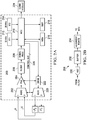
- FIG. 6 is a diagram of sampled waveforms y 1 ( i ) and y 2 ( i ) as in FIG. 5A ;
- FIG. 7A is a flow chart showing sample offset SAMP_OFFSET from cross correlation of y 1 ( i ) and y 2 ( i );
- FIG. 7B is a flow chart showing parabolic approximation of ⁇ ( FIG. 9A ) from cross correlation values;
- FIG. 8 is a flow chart showing determination of differential time of flight ( ⁇ TOF).
- FIGS. 9A through 9E are examples of differential time of flight ( ⁇ TOF) determination for various sample values
- FIG. 10A is a diagram showing estimated sample offset for FIGS. 9A through 9E ;
- FIG. 10B is a diagram showing estimated lead lag values for FIGS. 9A through 9E ;
- FIG. 10C is a diagram of estimated errors of differential time of flight ( ⁇ TOF) for FIGS. 9A through 9E ;
- FIG. 11 is a table showing a standard deviation for various lead lag and sample offset values.
- the preferred embodiments of the present invention provide significant advantages of ultrasonic differential time of flight ( ⁇ TOF) measurement techniques in a fluid or gas medium over methods of the prior art as will become evident from the following detailed description.
- ⁇ TOF differential time of flight
- FIG. 2A there is a circuit diagram of an ultrasonic circuit of the present invention for measuring fluid flow.
- signal r 12 is the ultrasonic signal produced by transducer UT 1 and received from transducer UT 2 as given by equation 4.
- signal r 21 is the ultrasonic signal produced by transducer UT 2 and received from transducer UT 1 as given by equation 5.
- the center frequency of the transmitting transducer is f C
- f(t) is the envelope of the received signal.
- r 12 f ( t )sin(2 ⁇ f C t ) [4]
- r 21 f ( t+ ⁇ t )sin(2 ⁇ f C ( t+ ⁇ t )) [5]
- the circuit 200 includes multiplex circuits 202 (MUX 2 ) and 220 (MUX 1 ) which are controlled by signals on control bus 226 .
- MUX 1 is coupled to receive an excitation signal from drive circuit 222 in response to micro control unit (MCU) 210 .
- MCU 210 is coupled to memory circuit 216 and to display circuit 218 .
- MCU 210 is also coupled to crystal oscillator circuit 212 , which controls measurement times, and to crystal oscillator circuit 214 , which controls excitation and sampling frequencies.
- MUX 1 When a logical 0 from control bus 226 is applied to MUX 1 , the excitation signal from drive circuit 222 is applied to UT 1 . UT 1 responsively transmits an ultrasonic signal to UT 2 . UT 2 produces received signal r 21 , which is applied to MUX 2 . The logical 0 applied to MUX 1 is also applied to MUX 2 so that r 21 is applied to programmable gain amplifier (PGA) 204 . PGA 204 amplifies r 21 and applies it to filter 206 . The filtered signal is then applied to signal processing unit 208 to calculate alignment points for r 21 .
- PGA programmable gain amplifier
- a logical 1 from control bus 226 is applied to MUX 1
- the excitation signal from drive circuit 222 is applied to UT 2 .
- UT 2 responsively transmits an ultrasonic signal to UT 1 .
- UT 1 produces received signal r 12 , which is applied to MUX 2 .
- the logical 1 applied to MUX 1 is also applied to MUX 2 so that r 12 is applied to programmable gain amplifier (PGA) 204 .
- PGA 204 amplifies r 12 and applies it to filter 206 .
- the filtered signal is then applied to signal processing unit 208 to determine respective alignment points as will be described in detail.
- the MCU calculates the differential time of flight ( ⁇ TOF) and fluid flow from the alignment points.
- the result is applied to communication module 224 and transmitted to a base station.
- the MCU also applies the result to display 218 .
- ⁇ TOF differential time of flight
- FIG. 2B is a circuit diagram showing detail of signal processing circuit 208 of FIG. 2A .
- the signal processing circuit alternately receives amplified and filtered ultrasonic signals from ultrasonic transducer UT 1 and UT 2 .
- Analog-to-Digital Converter (ADC) 230 samples the received signals at a sampling frequency determined by MCU 210 .
- the sampled signals are stored in buffer memory circuit 232 .
- circuit 234 calculates respective alignment points for each signal.
- Circuit 234 may be a digital signal processor, or any general purpose processor capable of real number calculations.
- Circuit 234 may also be a part of MCU 210 and may include both software and hardware. These alignment points are compared by MCU 210 to determine ⁇ TOF and fluid flow.
- FIGS. 3A and 3B illustrate potential measurement errors due to sampling that are resolved by embodiments of the present invention.
- FIG. 3A illustrates a sine wave that may be applied to ADC 230 ( FIG. 2B ).
- Signal samples 302 and 304 are separated in time by the inverse of the sampling frequency fs. For example, if the sampling frequency is 1 MHz, samples 302 and 304 are separated in time by 1 ⁇ s.
- the peak value 300 of the sine wave is taken as a true alignment point for signals from an ultrasonic transducer, the maximum error c occurs when either of signal samples 302 or 304 is used for alignment points.
- the ⁇ TOF may have a worst case error of c or 0.5 ⁇ s from either signal.
- FIG. 3B illustrates sine waves r 21 and r 12 that may be applied to ADC 230 ( FIG. 2B ).
- the true peak 310 of the positive half cycle of r 21 is separated in time from signal sample 312 by ⁇ .
- the true peak 314 of the positive half cycle of r 12 is separated in time from signal sample 316 by c. If signal samples 312 and 316 are aligned to calculate ⁇ TOF the resulting error may be as much as 2 c . This may be an acceptable error at higher sampling frequencies.
- embodiments of the present invention are directed to improved accuracy at lower sampling frequencies, thereby reducing system noise as well as cost.
- FIGS. 3C and 3D illustrate potential measurement errors due to mismatched ultrasonic transducers that are resolved by embodiments of the present invention.
- the transducers are fabricated separately from physical components and necessarily include some mismatch.
- FIG. 3C shows the envelopes of peak values of sampled signals r 21 and r 12 , where the signal samples are represented by black dots 320 - 326 . Each black dot represents a maximum sample value of one half cycle.
- the envelope of r 12 has a greater peak amplitude than the envelope of r 21 .
- Signal sample 324 corresponding to a first cycle of r 12 , may be selected as an alignment point when it exceeds threshold ⁇ .
- Signal sample 320 corresponding to a first cycle of r 21 , may not be selected as an alignment point, however, since it does not exceed threshold ⁇ due to the relatively lower amplitude.
- FIG. 3D shows the envelopes of maximum sample values of signals r 21 and r 12 , where the signal samples are represented by black dots 330 - 336 .
- the envelope of r 12 has the same amplitude as r 21 but a faster rise time than the envelope of r 21 .
- Signal sample 334 corresponding to a first cycle of r 12 , may be selected as an alignment point when it exceeds threshold ⁇ .
- Signal sample 330 corresponding to a first cycle of r 21 , may not be selected as an alignment point, however, since it does not exceed threshold ⁇ due to the relatively slower rise time.
- FIG. 4A there is a diagram of a sine wave illustrating parabolic interpolation to determine a local maximum value from sampled values.
- the method is given at https://ccrma.stanford.edu/ ⁇ jos/parshl/Peak_Detection_Steps_3.html.
- the three signal samples 402 through 406 are used to approximate the true peak 400 of the positive half cycle as well as the time 408 of the true peak as will be described in detail. Accuracy of the approximation depends on the ratio of the sampling frequency fs to the transducer center frequency fc. This approximation is reasonably accurate for a ratio of 4.
- FIG. 4B there is a diagram of a sine wave illustrating linear interpolation to determine a zero crossing time 410 from signal samples 412 and 414 .
- Accuracy of this method is comparable to parabolic interpolation and is also dependent on sampling frequency.
- signal samples 412 and 414 are selected to bracket the zero crossing of the sine wave. These sampled values define a line between the half cycles.
- the zero crossing times of ultrasonic signals r 12 and r 21 are then aligned to determine ⁇ TOF.
- accuracy of ⁇ TOF and fluid flow calculation are greatly improved.
- FIG. 5A there is a flow chart showing operation of signal processing circuit 208 ( FIG. 2A ) and MCU 210 ( FIG. 2B ).
- the flow chart illustrates a left branch beginning with UT 1 excitation pulses and a right branch beginning with UT 2 excitation pulses 500 .
- Both branches are the same except for different signal names, so only the right branch will be described in detail.
- the right branch signal names include a “1”
- the corresponding left branch signal names include a “2”.
- the UT 2 excitation pulses are preferably 10 to 20 square wave pulses as illustrated on the left of FIG. 7A .
- the excitation pulses preferably have a center frequency fc near the resonant frequency of the ultrasonic transducer.
- the excitation pulses from UT 2 are received by UT 1 and an absolute value of the amplitude y 1 ( i ) at the time t 1 ( i ) are sampled 502 at a sample frequency fs by ADC 230 and stored in buffer memory 232 ( FIG. 2B ).
- Envelope values of y 1 ( i ) signal samples are determined at block 504 as explained below with reference to FIG. 5B .
- the envelope z 1 ( i ) includes increasing values of y 1 ( i ) and constant values of the current maximum y 1 ( i ) when y 1 ( i ) is decreasing.
- Index i is initialized to zero and temporary variable yt is initialized to y 1 ( 0 ) at block 520 . Since sampling of the received ultrasonic signal 502 must begin prior to arrival of the signal, some initial samples may include system noise. Thus, initial samples of y 1 ( i ) having a magnitude less than a predetermined noise threshold ⁇ N (not shown) may be ignored.
- Decision block 522 tests whether y 1 ( i ) is greater than yt. If not (F), control passes to block 524 where z 1 ( i ) receives the current value of yt. Here, y 1 ( i ) stores the sample values and z 1 ( i ) stores the envelope values of y 1 ( i ) as will be explained in detail. Control then passes to decision block 526 to determine whether all N samples of y 1 ( i ) have been tested. If not (F), index i is incremented 528 , and control passes again to decision block 522 . As long as the test is false, yt holds the current maximum y 1 ( i ).
- index i 1 t is the index of the maximum y 1 ( i ) and z 1 ( i ) as determined at block 504 .
- point 404 is sampled at 1.3 ⁇ s and the sample interval is 0.1 ⁇ s, then the peak 400 occurs at 1.3 ⁇ s+0.1 ⁇ s*0.4012 or 1.34 ⁇ s 408 .
- point 404 is a local maximum value sampled at 1.3 ⁇ s
- point 400 is an approximation of the true maximum of the half cycle at 1.34 ⁇ s. It is highly advantageous to use the approximate time of the true maximum as an alignment point, since the time of sampled local maxima from UT 1 and UT 2 may differ as previously discussed with regard to FIGS. 3A and 3B .
- z 1 ( i ) envelope values are normalized 508 as shown at FIG. 5D .
- Index i is initialized to zero at block 540 .
- Control then passes to block 542 where z 1 ( i ) receives z 1 ( i ) divided by Y 1 MAX.
- Decision block 544 determines if all z 1 ( i ) have been normalized.
- N is the total number of envelope values. If there are more envelope values (F), i is incremented 546 and the next z 1 ( i ) sample is normalized. The process continues until all z 1 ( i ) values are normalized.
- the result is an envelope waveform stored in z 1 ( i ) as shown at FIG. 8B .
- This normalization advantageously avoids the problem of mismatched transducers having different amplitudes as previously discussed with reference to FIG. 3C .
- alignment points are calculated by threshold determination with optional linear interpolation.
- Index i is initialized to zero at block 550 .
- ⁇ 1 is preferably 25% of the maximum envelope value. If z 1 ( i ) is less than 01, control passes to decision block 566 to determine if all z 1 ( i ) have been tested.
- i is incremented 567 and control returns to decision block 552 .
- This process continues until z 1 ( i ) is greater than ⁇ 1 (T).
- Control then passes to block 554 to interpolate a time value tP 11 when the envelope z 1 ( i ) crosses the ⁇ 1 threshold. For example, if ⁇ 1 is 0.25, y 1 ( i ⁇ 1) is 0.23 at 8 ⁇ s, and y 1 ( i ) is 0.31 at 9 ⁇ s, tP 11 is 8.25 ⁇ s.
- control may pass directly to block 556 via path 555 and omit block 554 .
- the current value of i is stored in JP 11 . This is the index of the z 1 ( i ) sample that first exceeds threshold ⁇ 1 . Index i is then incremented and control then passes to decision block 558 .
- Decision block 558 tests whether z 1 ( i ) is greater than ⁇ 2 .
- ⁇ 2 is preferably 50% of the maximum envelope value. If not (F), decision block 564 determines if all z 1 ( i ) have been tested. If not, i is incremented 565 and control passes again to decision block 558 . This process continues until a current z 1 ( i ) is greater than ⁇ 2 (T). Control then passes to block 560 to interpolate a time value tP 12 when the envelope z 1 ( i ) crosses the ⁇ 2 threshold. As previously discussed, if the sample interval dt is sufficiently small, control may pass directly to block 562 via path 555 and omit block 560 . At block 562 the current value of i is stored in JP 12 . This is the index of the z 1 ( i ) sample that first exceeds threshold ⁇ 2 .
- the preceding values for the right branch of FIG. 5A are illustrated in the upper curve for envelope z 1 ( i ).
- the corresponding values for the left branch of FIG. 5A are illustrated in the lower curve for envelope z 2 ( i ).
- the time the upper curve leads or lags the lower curve is LEAD_LAG time.
- transmit time tt 2 is the time transducer UT 2 transmits an ultrasonic pulse to transducer UT 1 .
- sample 582 is the first normalized value of z 1 ( i ) that is greater than threshold ⁇ 1
- the preceding normalized value 580 is less than threshold ⁇ 1 .
- Block 554 interpolates time tP 11 at threshold ⁇ 1 as previously described.
- time t 1 (JP 11 ) of sample 582 may be used in lieu of tP 11 to calculate LEAD_LAG time.
- sample 586 is the first normalized value of z 1 ( i ) that is greater than threshold ⁇ 2 , and the preceding normalized value 584 is less than threshold ⁇ 2 .
- Block 560 interpolates time tP 12 at threshold ⁇ 2 as previously described.
- time t 1 (JP 12 ) of value 586 may be used in lieu of tP 12 to calculate LEAD_LAG time of flight.
- transmit time tt 1 is the time transducer UT 1 transmits an ultrasonic pulse to transducer UT 2 .
- Sample 592 is the first normalized value of z 2 ( i ) that is greater than threshold ⁇ 1 , and the preceding normalized value 590 is less than threshold ⁇ 1 .
- Block 554 interpolates time tP 21 at threshold ⁇ 1 as previously described. Alternatively, if sample interval dt is sufficiently small, time t 2 (JP 21 ) of sample 592 may be used in lieu of tP 21 to calculate LEAD_LAG time.
- sample 596 is the first normalized value of z 2 ( i ) that is greater than threshold ⁇ 2 , and the preceding normalized value 594 is less than threshold ⁇ 2 .
- Block 560 interpolates time tP 22 at threshold ⁇ 2 as previously described.
- time t 2 (JP 22 ) of value 596 may be used in lieu of tP 22 to calculate LEAD_LAG.
- Block 512 uses the alignment points determined by block 510 using the sample indices JP 11 , JP 12 , JP 21 , and JP 22 at FIG. 5F .
- Block 570 calculates the values TOF 1 and TOF 2 corresponding to thresholds ⁇ 1 and ⁇ 2 , respectively.
- TOF 1 is taken as a time difference between alignment points t 2 (JP 21 ) and t 1 (JP 11 ) from respective left and right branches less their respective transmit times tt 2 and tt 1 .
- TOF 2 is taken as a difference between alignment points t 2 (JP 22 ) and t 2 (JP 12 ) from respective left and right branches less their respective transmit times tt 2 and tt 1 .
- Control then passes to block 574 where TOF 1 and TOF 2 are averaged to produce a real value Re_LL of LEAD_LAG time. An integer value of Re_LL is then stored in LEAD_LAG.
- Block 512 at FIG. 5G uses the alignment points calculated by block 510 using the interpolated times tP 11 , tP 12 , tP 21 , and tP 22 as previously discussed.
- Block 572 calculates values TOF 1 and TOF 2 corresponding to thresholds ⁇ 1 and 02 , respectively.
- TOF 1 is taken as a time difference between alignment points tP 21 and tP 11 from respective left and right branches less their respective transmit times tt 2 and tt 1 .
- TOF 2 is taken as a difference between alignment points tP 22 and tP 12 from respective left and right branches less their respective transmit times tt 2 and tt 1 .
- Control then passes to block 574 where TOF 1 and TOF 2 are averaged to produce a real value Re_LL of LEAD_LAG time. An integer value of Re_LL is then stored in LEAD_LAG.
- FIG. 6 there is a diagram of sampled waveforms y 1 ( i ) and y 2 ( i ) as in FIG. 5A for an exemplary center frequency (fc) of 1 MHz and a sample frequency (fs) of 4 MHz. Individual samples are indicated by small geometries and connected by lines. It is important to note that the peak samples of each cycle are not the same as the peaks of the sampled waveform for each cycle.
- Cross correlation of y 1 ( i ) with y 2 ( i ) is stored in cross correlation array CORR as shown in equation [6] for N samples where k varies from ⁇ m to m.
- this is similar to sliding a y 2 ( i ) sample array from ⁇ m to m and multiplying them by corresponding samples of y 1 ( i ). Samples of y 2 ( i +k) for i+k less than 1 or greater than N are ignored or treated as zero. A sum of products for each k is stored in cross correlation array CORR(k).
- FIG. 7A is a flow chart showing determination of a sample offset SAMP_OFFSET from the cross correlation of y 1 ( i ) and y 2 ( i ).
- an initial value of k is computed by dividing the expected differential propagation time by the sample period (1/fs).
- the expected differential propagation time may be zero representing zero fluid flow. Alternatively, the expected differential propagation time may be taken from a preceding measurement.
- Cross correlation is then performed according to equation [6], and the result is stored in CORR(k). Subsequent cross correlation values are calculated as needed.
- index k is stored in k′.
- step 706 if CORR(k′ ⁇ 1) is greater than CORR(k′) then at step 708 k′ is replaced by k′ ⁇ 1, and step 706 is repeated.
- step 710 if CORR(k′+1) is greater than CORR(k′) then at step 712 k′ is replaced by k′+1, and step 710 is repeated.
- index k′ points to a maximum cross correlation value in CORR(k′).
- a sample offset SAMP_OFFSET is set to k ⁇ k′, and flow continues at FIG. 7B .
- FIG. 7B is a flow chart showing parabolic approximation of ⁇ ( FIG. 9A ) from cross correlation values computed at FIG. 7A .
- the resolution of the discrete cross correlation values may be insufficient to provide the accuracy needed for the differential propagation time.
- the actual differential propagation time may be between two discrete sample times. Interpolation can provide an improved estimate.
- the shape of the cross correlation function through the peak is approximately a cosine curve or a parabola. Accordingly, a cosine function or a parabolic function may be used for interpolation through three samples of CORR(k).
- the values of Z ⁇ 1 , Z 0 , and Z 1 at FIG. 9A are 0.4818, 0.8763, and ⁇ 0.4818, respectively.
- FIG. 8 there is a flow chart showing determination of differential time of flight ( ⁇ TOF) using independent estimates of differential time of flight calculated at FIGS. 5A through 5G and FIG. 7A .
- the first estimate of FIGS. 5A through 5G determines a difference between a time the first sampled signal y 1 ( i ) crosses a threshold and a time the second sampled signal y 2 ( i ) crosses the threshold.
- the second estimate of FIG. 7A is independent of the first estimate, because it cross correlates the first sampled signal with the second sampled signal to determine a time difference between the first sampled signal y 1 ( i ) and the second sampled signal y 2 ( i ).
- the second estimate therefore, does not depend on a threshold crossing as with the first estimate.
- a cycle slip error occurs when a cross correlation peak is identified on an incorrect cycle.
- a sample slip error occurs when an incorrect cross correlation sample is identified that may be on a correct cycle.
- the flow chart includes a left branch and a right branch.
- Block 800 determines if Re_LL is greater than or equal to 0. If true, y 1 leads y 2 and flow proceeds along the left branch to block 802 . If false, y 1 lags y 2 and flow proceeds along the right branch to block 812 .
- Blocks 802 and 812 are similar except for different inequalities.
- blocks 804 and 814 are similar except for different inequalities.
- FIG. 8 The flow chart of FIG. 8 will be explained with reference to the examples shown in FIGS. 9A through 9E .
- waveform y 1 leads waveform y 2 .
- Sample 900 is the cross correlation value of the initial k index at block 700 .
- k′ is initially set equal to k. ( FIG. 7A ).
- SAMP_OFFSET is set to zero at block 714 . Since the time difference of upstream and downstream waveforms crossing a threshold ( ⁇ 1 , ⁇ 2 FIG. 5E ) is less than a sample time (1/fs), LEAD_LAG is equal to zero. Thus, both tests 802 and 806 will prove false and block 806 will determine ⁇ TOF.
- FIG. 9B illustrates a second example of the flow chart of FIG. 8 for the cross correlation waveform of FIG. 9A .
- the timing offset between upstream and downstream waveforms is 330 ns (80 ns+250 ns) and cross correlation sample 902 is the cross correlation value of the initial k index at block 700 .
- k′ is initially set equal to k. ( FIG. 7A ).
- Block 706 tests whether CORR(k′ ⁇ 1) is greater than CORR(k′).
- Sample CORR(k′ ⁇ 1) is the first sample to the left of sample 902 and is greater than CORR(k′).
- Block 708 then subtracts one from k′, so that CORR(k′) effectively moves one sample to the left to what was previously CORR(k′ ⁇ 1).
- Block 706 again tests whether CORR(k′ ⁇ 1) is greater than CORR(k′). This time the test is false and control passes to block 710 .
- FIG. 9C illustrates a third example of the flow chart of FIG. 8 for the cross correlation waveform of FIG. 9A .
- the timing offset between upstream and downstream waveforms is 580 ns (80 ns+500 ns) and cross correlation sample 904 is the cross correlation value of the initial k index at block 700 .
- k′ is initially set equal to k. ( FIG. 7A ).
- Block 706 tests whether CORR(k′ ⁇ 1) is greater than CORR(k′).
- Sample CORR(k′ ⁇ 1) is the first sample to the left of sample 904 and is greater than CORR(k′).
- Block 708 then subtracts one from k′, so that CORR(k′) effectively moves one sample to the left to what was previously CORR(k′ ⁇ 1).
- Block 706 again tests whether CORR(k′ ⁇ 1) is greater than CORR(k′).
- CORR(k′ ⁇ 1) is the second sample to the left of sample 904 and is greater than CORR(k′).
- Block 708 again subtracts one from k′, so that CORR(k′) effectively moves two samples to the left from sample 904 .
- Block 706 again tests whether CORR(k′ ⁇ 1) is greater than CORR(k′). This time the test is false and control passes to block 710 .
- the test at block 710 is also false, and block 714 sets SAMP_OFFSET to two.
- FIG. 9D illustrates a fourth example of the flow chart of FIG. 8 for the cross correlation waveform of FIG. 9A .
- the timing offset between upstream and downstream waveforms is 830 ns (80 ns+750 ns) and cross correlation sample 906 is the cross correlation value of the initial k index at block 700 .
- k′ is initially set equal to k. ( FIG. 7A ).
- Block 706 tests whether CORR(k′ ⁇ 1) is greater than CORR(k′).
- Sample CORR(k′ ⁇ 1) is the first sample to the left of sample 906 and is less than CORR(k′).
- Control passes to block 710 .
- Block 710 tests whether CORR(k′+1) is greater than CORR(k′).
- CORR(k′+1) is the first sample to the right of sample 906 and is greater than CORR(k′).
- Block 712 then adds one to k′, so that CORR(k′) effectively moves one sample to the right from sample 906 .
- FIG. 9E illustrates a fifth example of the flow chart of FIG. 8 for the cross correlation waveform of FIG. 9A .
- the timing offset between upstream and downstream waveforms is 1080 ns (80 ns+1000 ns) and cross correlation sample 908 is the cross correlation value of the initial k index at block 700 .
- k′ is initially set equal to k. ( FIG. 7A ). Both tests at block 706 and 710 are false, so CORR(k′) is not moved, and SAMP_OFFSET is set to zero by block 714 . Since the time difference of upstream and downstream waveforms crossing a threshold ( ⁇ 1 , ⁇ 2 FIG.
- LEAD_LAG 4 ( FIG. 5F or 5G ).
- the test at block 804 is true, because the product of LEAD_LAG and fc/fs is 1. Thus, a cycle slip has occurred, and block 808 will set ⁇ TOF to 1000 ns+80 ns or 1080 ns.
- FIG. 10A there is a diagram showing estimated sample offset for FIGS. 9A through 9E as a function of differential time of flight.
- the estimated value of SAMP_OFFSET is 0 for the example of FIG. 9A , 1 for the example of FIG. 9B , and 2 for the example of FIG. 9C .
- no cycle slip occurs.
- the differential time of flight is determined by 0, 1, or 2 respective sample slips.
- SAMP_OFFSET is ⁇ 1.
- the differential time of flight therefore, is 1000 ns-250 ns+80 ns or 830 ns.
- FIG. 9E is the same as in FIG. 9A except that the initial correlation value 908 is displaced by one cycle with respect to correlation value 900 .
- the pattern of FIG. 10A repeats for increasing differential delay offsets.
- FIG. 10B is a diagram showing estimated LEAD_LAG values for FIGS. 9A through 9E as a function of differential time of flight.
- the LEAD_LAG value from FIG. 5F or 5G is an average of two time of flight (TOF 1 and TOF 2 ) measurements. Each time of flight measurement is a time difference between a time y 1 and y 2 envelopes cross a threshold ( ⁇ 1 , ⁇ 2 FIG. 5E ).
- FIG. 10C is a diagram of estimated errors of differential time of flight ( ⁇ TOF) for FIGS. 9A through 9E . Recall that no cycle slip was detected for the examples of FIGS. 9A through 9C , and errors are less than 0.1 ns. Examples of FIGS. 9D and 9E include compensation for both cycle slip and sample slip. Here, however, maximum errors are less than 1.2 ns.
- FIG. 11 is a summary table showing a standard deviation for various lead lag and sample offset values.
- the first column shows differential delay offsets from 0 to 1.25 ⁇ s in 50 ns increments.
- the second and third columns show corresponding values for Re_LL and SAMP_OFFSET.
- the fourth column shows the corresponding standard deviation for each differential delay offset.
- the present invention advantageously compensates for sample slip and cycle slip.
- the present invention provides improved accuracy with small standard deviation over a wide range of differential delay offset values.
- the method disclosed in U.S. Nonprovisional application Ser. No. 14/051,623 may be used to obtain a second independent estimate of differential time of flight rather than the cross correlation method of equation [6].
- received signals of FIG. 2A are given by equations [4] and [5]. These signals are received alternately so that transducer UT 1 transmits when transducer UT 2 receives, and transducer UT 2 transmits when transducer UT 1 receives.
- the received signals may be applied to quadrature mixer circuits 204 and 206 (FIG. 2 of U.S. Nonprovisional application Ser. No. 14/051,623).
- Mixer circuit 204 multiplies the received signal by the modulating signal sin(2 ⁇ (f C + ⁇ f)t) and applies the resulting in phase signal to a low pass filter.
- Mixer circuit 206 multiplies the received signal by the modulating signal cos(2 ⁇ (fC+ ⁇ f)t) and applies the resulting quadrature signal to a low pass filter.
- ⁇ f is a frequency error term of the mixer frequency with respect to the transducer center frequency.
- the output signals from in phase mixer 204 are given by equations [10] and [11].
- the output signals from quadrature mixer 206 are given by equations [12] and [13].
- the output signals of equations [10] and [11] are filtered to produce filtered output signals given by equations [14] and [15], respectively.
- the output signals of equations [12] and [13] are filtered to produce filtered output signals given by equations [16] and [17], respectively.
- the signal pair of equations [15] and [17] is not a delayed version of the signal pair of equations [14] and [16].
- the received signal of equation [5] is a delayed version of the signal of equation [4].
- ⁇ ⁇ ⁇ t a ⁇ ⁇ tan ⁇ ( r ⁇ Q 21 ⁇ ( t ) r ⁇ I 21 ⁇ ( t ) ) - a ⁇ ⁇ tan ⁇ ( r ⁇ Q 12 ⁇ ( t ) r ⁇ I 12 ⁇ ( t ) ) [ 18 ]
- alignment points of received ultrasonic waveforms may be generated for positive half cycles, negative half cycles, of both.
- linear zero crossing alignment points may be generated from received ultrasonic waveforms for positive slope, negative slope, or both.
- peak and zero crossing alignment point calculation may only be necessary for relatively low sampling frequency or for greater accuracy. Otherwise, selected local sample values near half cycle peaks or zero crossings may be used as alignment points.
Landscapes
- Physics & Mathematics (AREA)
- General Physics & Mathematics (AREA)
- Engineering & Computer Science (AREA)
- Electromagnetism (AREA)
- Fluid Mechanics (AREA)
- Mathematical Optimization (AREA)
- Mathematical Physics (AREA)
- Mathematical Analysis (AREA)
- Computational Mathematics (AREA)
- Pure & Applied Mathematics (AREA)
- Theoretical Computer Science (AREA)
- Data Mining & Analysis (AREA)
- Computing Systems (AREA)
- Databases & Information Systems (AREA)
- Software Systems (AREA)
- General Engineering & Computer Science (AREA)
- Algebra (AREA)
- Investigating Or Analyzing Materials By The Use Of Ultrasonic Waves (AREA)
- Measuring Volume Flow (AREA)
Abstract
Description
r 12 =f(t)sin(2πf C t) [4]
r 21 =f(t+δt)sin(2πf C(t+δt)) [5]
CORR(k)=Σi=1 N y1(i)y2(i+k) [6]
r I 12(t)=f(t)sin(2πf C t)sin(2π(f C +δf)t) [10]
r I 21(t)=f(t+δt)sin(2πf C(t+δt))sin(2π(f C +δf)t) [11]
r Q 12(t)=f(t)sin(2πf C t)cos(2π(f C δf)t) [12]
r Q 21(t)=f(t+δt)sin(2πf C(t+δt))cos(2π(f C +δf)t) [13]
{tilde over (r)} I 12(t)=f(t)sin(2πδft) [14]
{tilde over (r)} I 21(t)=f(t+δt)sin(2π(f C δt+δft) [15]
{tilde over (r)} Q 12(t)=f(t)cos(2πδft) [16]
{tilde over (r)} Q 21(t)=f(t+δt)cos(2π(f C δt+δft)) [17]
Claims (15)
Priority Applications (6)
| Application Number | Priority Date | Filing Date | Title |
|---|---|---|---|
| US14/300,303 US10801868B2 (en) | 2014-06-10 | 2014-06-10 | Extended range ADC flow meter |
| EP15807199.3A EP3155382B1 (en) | 2014-06-10 | 2015-06-10 | Extended range adc flow meter |
| CN201580030813.8A CN106461437B (en) | 2014-06-10 | 2015-06-10 | Extended Range ADC Flow Meter |
| PCT/US2015/035210 WO2015191785A1 (en) | 2014-06-10 | 2015-06-10 | Extended range adc flow meter |
| US17/008,156 US11255708B2 (en) | 2014-06-10 | 2020-08-31 | Extended range ADC flow meter |
| US17/574,650 US11747181B2 (en) | 2014-06-10 | 2022-01-13 | Extended range ADC flow meter |
Applications Claiming Priority (1)
| Application Number | Priority Date | Filing Date | Title |
|---|---|---|---|
| US14/300,303 US10801868B2 (en) | 2014-06-10 | 2014-06-10 | Extended range ADC flow meter |
Related Child Applications (1)
| Application Number | Title | Priority Date | Filing Date |
|---|---|---|---|
| US17/008,156 Continuation US11255708B2 (en) | 2014-06-10 | 2020-08-31 | Extended range ADC flow meter |
Publications (2)
| Publication Number | Publication Date |
|---|---|
| US20150355001A1 US20150355001A1 (en) | 2015-12-10 |
| US10801868B2 true US10801868B2 (en) | 2020-10-13 |
Family
ID=54769339
Family Applications (3)
| Application Number | Title | Priority Date | Filing Date |
|---|---|---|---|
| US14/300,303 Active 2038-04-06 US10801868B2 (en) | 2014-06-10 | 2014-06-10 | Extended range ADC flow meter |
| US17/008,156 Active US11255708B2 (en) | 2014-06-10 | 2020-08-31 | Extended range ADC flow meter |
| US17/574,650 Active US11747181B2 (en) | 2014-06-10 | 2022-01-13 | Extended range ADC flow meter |
Family Applications After (2)
| Application Number | Title | Priority Date | Filing Date |
|---|---|---|---|
| US17/008,156 Active US11255708B2 (en) | 2014-06-10 | 2020-08-31 | Extended range ADC flow meter |
| US17/574,650 Active US11747181B2 (en) | 2014-06-10 | 2022-01-13 | Extended range ADC flow meter |
Country Status (4)
| Country | Link |
|---|---|
| US (3) | US10801868B2 (en) |
| EP (1) | EP3155382B1 (en) |
| CN (1) | CN106461437B (en) |
| WO (1) | WO2015191785A1 (en) |
Cited By (4)
| Publication number | Priority date | Publication date | Assignee | Title |
|---|---|---|---|---|
| US11175165B2 (en) * | 2017-08-29 | 2021-11-16 | Nederlandse Organisatie Voor Toegepast-Natuurwetenschappelijk Onderzoek Tno | Acoustic measurement of a fluid flow |
| US11215489B2 (en) * | 2017-03-07 | 2022-01-04 | Abb Schweiz Ag | Apparatus and method for measuring the flow velocity of a fluid in a pipe |
| US20220136878A1 (en) * | 2014-06-10 | 2022-05-05 | Texas Instruments Incorporated | Extended range adc flow meter |
| US11340100B2 (en) * | 2018-12-08 | 2022-05-24 | Diehl Metering Gmbh | Method for evaluating measurement data sequences of an ultrasonic flow measuring device and ultrasonic flow measuring device |
Families Citing this family (7)
| Publication number | Priority date | Publication date | Assignee | Title |
|---|---|---|---|---|
| DE102016006244A1 (en) * | 2016-01-14 | 2017-07-20 | Diehl Metering Gmbh | Ultrasonic fluid meter and method for flow and / or volume determination of a flowing medium |
| US11353347B2 (en) | 2017-03-22 | 2022-06-07 | Texas Instruments Incorporated | Ultrasonic flow meter and excitation method |
| FR3068126B1 (en) * | 2017-06-27 | 2019-08-30 | Sagemcom Energy & Telecom Sas | METHOD FOR MEASURING A SPEED OF A FLUID |
| US12449290B2 (en) | 2018-12-26 | 2025-10-21 | Texas Instruments Incorporated | Dynamic temperature calibration of ultrasonic transducers |
| US11725968B2 (en) * | 2020-06-08 | 2023-08-15 | Honeywell International Inc. | Measurement of absolute time of flight in an ultrasonic meter using received and reflected waves |
| CN114252115B (en) * | 2021-12-21 | 2024-11-12 | 天津大学 | A method for measuring the propagation time of ultrasonic flowmeters for wet gas measurement |
| CN115113512B (en) * | 2022-05-26 | 2024-03-29 | 合肥综合性国家科学中心人工智能研究院(安徽省人工智能实验室) | Pulse sampling method, sampling system, device and computer readable storage medium |
Citations (19)
| Publication number | Priority date | Publication date | Assignee | Title |
|---|---|---|---|---|
| US4183244A (en) * | 1977-07-26 | 1980-01-15 | Fuji Electric Co., Ltd. | Ultrasonic flow rate measuring apparatus |
| US4748857A (en) * | 1986-02-26 | 1988-06-07 | Fuji Electric Co., Ltd. | Ultrasonic apparatus for measuring the flow velocity of a fluid |
| US5814737A (en) * | 1996-10-04 | 1998-09-29 | Dieterich Technology Holding Corp. | Apparatus and method of detecting an ultrasonic signal |
| FR2781048A1 (en) | 1998-07-10 | 2000-01-14 | Faure Herman | CROSS MEASUREMENTS OF THE ACOUSTIC SIGNALS OF A FLOWMETER |
| WO2000003207A1 (en) | 1998-07-10 | 2000-01-20 | Panametrics, Inc. | Guided mode flow measurement system |
| US6119070A (en) * | 1995-09-25 | 2000-09-12 | Schlumberger Industries, S.A. | Method for acoustically measuring a fluid flow rate |
| US20020143479A1 (en) * | 2001-02-15 | 2002-10-03 | Satoshi Fukuhara | Ultrasonic flowmeter |
| US6535206B1 (en) * | 2000-02-18 | 2003-03-18 | Intel Corporation | Ultrasonic wireless pen position determination system and method |
| US6634240B1 (en) * | 1998-08-19 | 2003-10-21 | Siemens-Elema Ab | Zero crossing detector and method of determining a zero crossing point |
| US20050288873A1 (en) * | 2004-06-28 | 2005-12-29 | Nelson Urdaneta | Ultrasonic liquid flow controller |
| JP2009074879A (en) | 2007-09-20 | 2009-04-09 | Hitachi-Ge Nuclear Energy Ltd | Ultrasonic core flow measuring device and ultrasonic flow meter |
| US20100288055A1 (en) * | 2009-05-12 | 2010-11-18 | Roland Mueller | Transit time correction in a flow sensor |
| CN101922954A (en) | 2009-06-17 | 2010-12-22 | 上海一诺仪表有限公司 | Method for processing envelope line of ultrasonic measuring signal |
| CN102589627A (en) | 2012-02-23 | 2012-07-18 | 北京理工大学 | Absolute propagation time measuring method for ultrasonic flow meter |
| WO2013079074A1 (en) | 2011-12-02 | 2013-06-06 | Kamstrup A/S | Ultrasonic flow meter with digitally under-sampled flow measurements |
| US20140012518A1 (en) | 2012-07-09 | 2014-01-09 | Texas Instruments Incorporated | Flow meter |
| US20140107950A1 (en) * | 2012-10-12 | 2014-04-17 | Texas Instruments Incorporated | Bandpass adc sampling for fluid velocity determination |
| US20140303910A1 (en) * | 2013-04-04 | 2014-10-09 | Texas Instruments Incorporated | Extended range adc flow meter |
| US20150292926A1 (en) * | 2012-11-05 | 2015-10-15 | Panasonic Intellectual Property Management Co., Ltd. | Flow meter device and flow rate calculation method thereof |
Family Cites Families (16)
| Publication number | Priority date | Publication date | Assignee | Title |
|---|---|---|---|---|
| US3498290A (en) * | 1966-04-22 | 1970-03-03 | Robert F Shaw | Pulsed doppler volumetric blood flowmeter |
| US4280365A (en) * | 1979-10-10 | 1981-07-28 | Leeds & Northrup Company | Ultrasonic Doppler flowmeter with correction for vibratory signals at zero-flow conditions |
| US4856321A (en) * | 1983-07-29 | 1989-08-15 | Panametrics, Inc. | Apparatus and methods for measuring fluid flow parameters |
| US4596133A (en) * | 1983-07-29 | 1986-06-24 | Panametrics, Inc. | Apparatus and methods for measuring fluid flow parameters |
| US4754650A (en) * | 1983-07-29 | 1988-07-05 | Panametrics, Inc. | Apparatus and methods for measuring fluid flow parameters |
| US6330831B1 (en) * | 1998-10-20 | 2001-12-18 | Panametrics, Inc. | Stream-cleaned differential reflection coefficient sensor |
| US6293156B1 (en) * | 1999-01-22 | 2001-09-25 | Panametrics, Inc. | Coherent multi-path flow measurement system |
| JP3877484B2 (en) * | 2000-02-29 | 2007-02-07 | アルプス電気株式会社 | Input device |
| KR100893114B1 (en) * | 2002-01-31 | 2009-04-14 | 후지쯔 가부시끼가이샤 | Ultrasonic distance measuring device and method for coordinate input |
| US7182241B2 (en) * | 2002-08-09 | 2007-02-27 | Micron Technology, Inc. | Multi-functional solder and articles made therewith, such as microelectronic components |
| AU2003902318A0 (en) * | 2003-05-14 | 2003-05-29 | Vision Fire And Security Pty Ltd | Improved Sensing Apparatus And Method |
| JP4101791B2 (en) * | 2004-09-17 | 2008-06-18 | シャープ株式会社 | Coordinate value input system, coordinate value input method, coordinate value input program, computer-readable recording medium |
| US10801868B2 (en) * | 2014-06-10 | 2020-10-13 | Texas Instruments Incorporated | Extended range ADC flow meter |
| WO2016016818A1 (en) * | 2014-07-29 | 2016-02-04 | Hydrovision Asia Pte Ltd | Improved signal travel time flow meter |
| US10830619B2 (en) * | 2015-05-12 | 2020-11-10 | Texas Instruments Incorporated | Envelope based sample correction for digital flow metrology |
| US11353347B2 (en) * | 2017-03-22 | 2022-06-07 | Texas Instruments Incorporated | Ultrasonic flow meter and excitation method |
-
2014
- 2014-06-10 US US14/300,303 patent/US10801868B2/en active Active
-
2015
- 2015-06-10 WO PCT/US2015/035210 patent/WO2015191785A1/en not_active Ceased
- 2015-06-10 EP EP15807199.3A patent/EP3155382B1/en active Active
- 2015-06-10 CN CN201580030813.8A patent/CN106461437B/en active Active
-
2020
- 2020-08-31 US US17/008,156 patent/US11255708B2/en active Active
-
2022
- 2022-01-13 US US17/574,650 patent/US11747181B2/en active Active
Patent Citations (22)
| Publication number | Priority date | Publication date | Assignee | Title |
|---|---|---|---|---|
| US4183244A (en) * | 1977-07-26 | 1980-01-15 | Fuji Electric Co., Ltd. | Ultrasonic flow rate measuring apparatus |
| US4748857A (en) * | 1986-02-26 | 1988-06-07 | Fuji Electric Co., Ltd. | Ultrasonic apparatus for measuring the flow velocity of a fluid |
| US6119070A (en) * | 1995-09-25 | 2000-09-12 | Schlumberger Industries, S.A. | Method for acoustically measuring a fluid flow rate |
| US5814737A (en) * | 1996-10-04 | 1998-09-29 | Dieterich Technology Holding Corp. | Apparatus and method of detecting an ultrasonic signal |
| FR2781048A1 (en) | 1998-07-10 | 2000-01-14 | Faure Herman | CROSS MEASUREMENTS OF THE ACOUSTIC SIGNALS OF A FLOWMETER |
| WO2000003207A1 (en) | 1998-07-10 | 2000-01-20 | Panametrics, Inc. | Guided mode flow measurement system |
| US6634240B1 (en) * | 1998-08-19 | 2003-10-21 | Siemens-Elema Ab | Zero crossing detector and method of determining a zero crossing point |
| US6535206B1 (en) * | 2000-02-18 | 2003-03-18 | Intel Corporation | Ultrasonic wireless pen position determination system and method |
| US20020143479A1 (en) * | 2001-02-15 | 2002-10-03 | Satoshi Fukuhara | Ultrasonic flowmeter |
| CN101006328A (en) | 2004-06-28 | 2007-07-25 | 迅捷公司 | Ultrasonic liquid flow controller |
| US20050288873A1 (en) * | 2004-06-28 | 2005-12-29 | Nelson Urdaneta | Ultrasonic liquid flow controller |
| JP2009074879A (en) | 2007-09-20 | 2009-04-09 | Hitachi-Ge Nuclear Energy Ltd | Ultrasonic core flow measuring device and ultrasonic flow meter |
| US20100288055A1 (en) * | 2009-05-12 | 2010-11-18 | Roland Mueller | Transit time correction in a flow sensor |
| CN101922954A (en) | 2009-06-17 | 2010-12-22 | 上海一诺仪表有限公司 | Method for processing envelope line of ultrasonic measuring signal |
| WO2013079074A1 (en) | 2011-12-02 | 2013-06-06 | Kamstrup A/S | Ultrasonic flow meter with digitally under-sampled flow measurements |
| US20140318268A1 (en) * | 2011-12-02 | 2014-10-30 | Kamstrup A/S | Ultrasonic flow meter with digitally under-sampled flow measurements |
| CN102589627A (en) | 2012-02-23 | 2012-07-18 | 北京理工大学 | Absolute propagation time measuring method for ultrasonic flow meter |
| US20140012518A1 (en) | 2012-07-09 | 2014-01-09 | Texas Instruments Incorporated | Flow meter |
| US9689726B2 (en) * | 2012-07-09 | 2017-06-27 | Texas Instruments Incorporated | Flow meter |
| US20140107950A1 (en) * | 2012-10-12 | 2014-04-17 | Texas Instruments Incorporated | Bandpass adc sampling for fluid velocity determination |
| US20150292926A1 (en) * | 2012-11-05 | 2015-10-15 | Panasonic Intellectual Property Management Co., Ltd. | Flow meter device and flow rate calculation method thereof |
| US20140303910A1 (en) * | 2013-04-04 | 2014-10-09 | Texas Instruments Incorporated | Extended range adc flow meter |
Non-Patent Citations (3)
| Title |
|---|
| Extended European Search Report from EP 15807199.3; dated Jan. 31, 2018; 10 pages. |
| Notification of CN First Office Action and Search Report; dated Dec. 4, 2018; 5 pages. |
| State Intellictual Property Office of PRC Notification of Second Office Action and Search Report for, Z16111354EPCN, Application No. 2015800308138; dated Jun. 4, 2019; 4 pages. |
Cited By (5)
| Publication number | Priority date | Publication date | Assignee | Title |
|---|---|---|---|---|
| US20220136878A1 (en) * | 2014-06-10 | 2022-05-05 | Texas Instruments Incorporated | Extended range adc flow meter |
| US11747181B2 (en) * | 2014-06-10 | 2023-09-05 | Texas Instruments Incorporated | Extended range ADC flow meter |
| US11215489B2 (en) * | 2017-03-07 | 2022-01-04 | Abb Schweiz Ag | Apparatus and method for measuring the flow velocity of a fluid in a pipe |
| US11175165B2 (en) * | 2017-08-29 | 2021-11-16 | Nederlandse Organisatie Voor Toegepast-Natuurwetenschappelijk Onderzoek Tno | Acoustic measurement of a fluid flow |
| US11340100B2 (en) * | 2018-12-08 | 2022-05-24 | Diehl Metering Gmbh | Method for evaluating measurement data sequences of an ultrasonic flow measuring device and ultrasonic flow measuring device |
Also Published As
| Publication number | Publication date |
|---|---|
| EP3155382A4 (en) | 2018-02-28 |
| EP3155382B1 (en) | 2020-03-04 |
| US20220136878A1 (en) | 2022-05-05 |
| US20150355001A1 (en) | 2015-12-10 |
| CN106461437A (en) | 2017-02-22 |
| US11255708B2 (en) | 2022-02-22 |
| CN106461437B (en) | 2020-07-17 |
| US20200400472A1 (en) | 2020-12-24 |
| EP3155382A1 (en) | 2017-04-19 |
| WO2015191785A1 (en) | 2015-12-17 |
| US11747181B2 (en) | 2023-09-05 |
Similar Documents
| Publication | Publication Date | Title |
|---|---|---|
| US20220136878A1 (en) | Extended range adc flow meter | |
| US9689726B2 (en) | Flow meter | |
| US12474190B2 (en) | Envelope based sample correction for digital flow metrology | |
| US9494676B2 (en) | Paired ZF sampling for pulse running time filling level sensor | |
| CN106772393B (en) | A kind of improved ultrasonic ranging method based on flight time detection | |
| US10852168B2 (en) | Method of measuring time of flight of an ultrasound pulse | |
| US20140107950A1 (en) | Bandpass adc sampling for fluid velocity determination | |
| US10955273B2 (en) | Extended range ADC flow meter | |
| CN110799810B (en) | Method for measuring fluid velocity | |
| US20210003436A1 (en) | Time-of-flight generating circuit and chip, flow meter and method of the same | |
| EP2642256B1 (en) | Measurement arrangement and method | |
| US10605779B2 (en) | Method for determining properties of a medium and device for determining properties of a medium | |
| JP4520552B2 (en) | Method and apparatus for measuring the flow velocity of a fluid flow | |
| US10727787B2 (en) | Flow detection with quadrature demodulation | |
| WO2015055209A1 (en) | Flow meter algorithm | |
| Han et al. | Measurement range expansion of continuous wave ultrasonic anemometer | |
| CN103792384A (en) | Fluid flow velocity measurement method with adjustable measuring range ratio based on ultrasonic cross-correlation technology | |
| JPH11351928A (en) | Flow meter and flow measurement method | |
| Lucena et al. | An innovative ultrasonic time of flight method based on extended Kalman filter for wind speed measurement | |
| JPWO2005119182A1 (en) | Fluid flow rate measuring method and flow rate measuring device | |
| Namas et al. | A feasible and accurate technique for determining the time-of-flight in ultrasonic distance measurements | |
| Nemade et al. | Sensing turbulence transit time by pulsed ultrasound for single-phase fluid flow measurement | |
| Zimmermann et al. | Flow rate estimation using acoustic field distortions caused by turbulent flows: time-reversal approach | |
| Maskell et al. | A discrete-time quadrature time-of-arrival estimator for determining the subsample delay between narrowband ultrasound signals |
Legal Events
| Date | Code | Title | Description |
|---|---|---|---|
| AS | Assignment |
Owner name: TEXAS INSTRUMENTS INCORPORATED, TEXAS Free format text: ASSIGNMENT OF ASSIGNORS INTEREST;ASSIGNORS:DABAK, ANAND;RAMANAN, VENKATA;REEL/FRAME:035529/0092 Effective date: 20140610 |
|
| STPP | Information on status: patent application and granting procedure in general |
Free format text: FINAL REJECTION MAILED |
|
| STPP | Information on status: patent application and granting procedure in general |
Free format text: DOCKETED NEW CASE - READY FOR EXAMINATION |
|
| STPP | Information on status: patent application and granting procedure in general |
Free format text: NON FINAL ACTION MAILED |
|
| STPP | Information on status: patent application and granting procedure in general |
Free format text: RESPONSE TO NON-FINAL OFFICE ACTION ENTERED AND FORWARDED TO EXAMINER |
|
| STPP | Information on status: patent application and granting procedure in general |
Free format text: AWAITING TC RESP, ISSUE FEE PAYMENT VERIFIED |
|
| STCF | Information on status: patent grant |
Free format text: PATENTED CASE |
|
| MAFP | Maintenance fee payment |
Free format text: PAYMENT OF MAINTENANCE FEE, 4TH YEAR, LARGE ENTITY (ORIGINAL EVENT CODE: M1551); ENTITY STATUS OF PATENT OWNER: LARGE ENTITY Year of fee payment: 4 |