US10801192B2 - Shower head liquid agent dispenser - Google Patents
Shower head liquid agent dispenser Download PDFInfo
- Publication number
- US10801192B2 US10801192B2 US15/178,832 US201615178832A US10801192B2 US 10801192 B2 US10801192 B2 US 10801192B2 US 201615178832 A US201615178832 A US 201615178832A US 10801192 B2 US10801192 B2 US 10801192B2
- Authority
- US
- United States
- Prior art keywords
- tee fitting
- storage tank
- valve
- liquid agent
- aerator
- Prior art date
- Legal status (The legal status is an assumption and is not a legal conclusion. Google has not performed a legal analysis and makes no representation as to the accuracy of the status listed.)
- Active
Links
Images


Classifications
-
- E—FIXED CONSTRUCTIONS
- E03—WATER SUPPLY; SEWERAGE
- E03C—DOMESTIC PLUMBING INSTALLATIONS FOR FRESH WATER OR WASTE WATER; SINKS
- E03C1/00—Domestic plumbing installations for fresh water or waste water; Sinks
- E03C1/02—Plumbing installations for fresh water
- E03C1/04—Water-basin installations specially adapted to wash-basins or baths
- E03C1/046—Adding soap, disinfectant, or the like in the supply line or at the water outlet
-
- A—HUMAN NECESSITIES
- A47—FURNITURE; DOMESTIC ARTICLES OR APPLIANCES; COFFEE MILLS; SPICE MILLS; SUCTION CLEANERS IN GENERAL
- A47K—SANITARY EQUIPMENT; ACCESSORIES THEREFOR, e.g. TOILET ACCESSORIES
- A47K5/00—Holders or dispensers for soap, toothpaste or the like
- A47K5/06—Dispensers for soap
- A47K5/12—Dispensers for soap for liquid or pasty soap
-
- B—PERFORMING OPERATIONS; TRANSPORTING
- B05—SPRAYING OR ATOMISING IN GENERAL; APPLYING FLUENT MATERIALS TO SURFACES, IN GENERAL
- B05B—SPRAYING APPARATUS; ATOMISING APPARATUS; NOZZLES
- B05B7/00—Spraying apparatus for discharge of liquids or other fluent materials from two or more sources, e.g. of liquid and air, of powder and gas
- B05B7/24—Spraying apparatus for discharge of liquids or other fluent materials from two or more sources, e.g. of liquid and air, of powder and gas with means, e.g. a container, for supplying liquid or other fluent material to a discharge device
- B05B7/2402—Apparatus to be carried on or by a person, e.g. by hand; Apparatus comprising containers fixed to the discharge device
- B05B7/244—Apparatus to be carried on or by a person, e.g. by hand; Apparatus comprising containers fixed to the discharge device using carrying liquid for feeding, e.g. by suction, pressure or dissolution, a carried liquid from the container to the nozzle
- B05B7/2443—Apparatus to be carried on or by a person, e.g. by hand; Apparatus comprising containers fixed to the discharge device using carrying liquid for feeding, e.g. by suction, pressure or dissolution, a carried liquid from the container to the nozzle the carried liquid and the main stream of carrying liquid being brought together downstream of the container before discharge
-
- E—FIXED CONSTRUCTIONS
- E03—WATER SUPPLY; SEWERAGE
- E03C—DOMESTIC PLUMBING INSTALLATIONS FOR FRESH WATER OR WASTE WATER; SINKS
- E03C1/00—Domestic plumbing installations for fresh water or waste water; Sinks
- E03C1/02—Plumbing installations for fresh water
- E03C1/08—Jet regulators or jet guides, e.g. anti-splash devices
- E03C1/084—Jet regulators with aerating means
-
- B—PERFORMING OPERATIONS; TRANSPORTING
- B05—SPRAYING OR ATOMISING IN GENERAL; APPLYING FLUENT MATERIALS TO SURFACES, IN GENERAL
- B05B—SPRAYING APPARATUS; ATOMISING APPARATUS; NOZZLES
- B05B1/00—Nozzles, spray heads or other outlets, with or without auxiliary devices such as valves, heating means
- B05B1/14—Nozzles, spray heads or other outlets, with or without auxiliary devices such as valves, heating means with multiple outlet openings; with strainers in or outside the outlet opening
- B05B1/18—Roses; Shower heads
Definitions
- the present invention relates generally to shower accessories, and more particularly to a liquid agent dispenser for use with a shower head.
- While taking a shower it is common to utilize some type of cleaning agent such as soap, shampoo, conditioner, and/or body wash, for example to ensure a user is able to thoroughly clean their body.
- cleaning agent such as soap, shampoo, conditioner, and/or body wash
- residential showers are often littered with many different bottles that are often scattered along the floor and/or shelves. When so located, users may have difficulty identifying a proper bottle, or may slip on a bottle while bathing under the shower stream.
- liquid agent dispenser that can store and dispense any type of liquid agent directly into a shower head, so as to alleviate the drawbacks of the above noted devices.
- the present invention is directed to a shower head liquid agent dispenser.
- One embodiment of the present invention can include a storage tank having a hollow interior space for storing a liquid agent such as soap, shampoo, conditioner and/or body wash.
- a first tubular member is connected to the bottom end of the storage tank and functions to feed the stored agent to a valve which can be manipulated by a user to between an on and off position, in order to control an operation of the device.
- a second tubular member can feed the liquid agent into a tee fitting which is connected to a building's shower arm. The tee fitting can function to mix the liquid agent with shower water and dispense the same into the shower head.
- Another embodiment of the present invention can include an aerator that is interposed between the tee fitting and the shower arm.
- Yet another embodiment of the present invention can include a shower head having the above described liquid agent dispenser secured thereon.
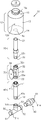
- FIG. 1 is an exploded parts view of a shower head liquid agent dispenser that is useful for understanding the inventive concepts disclosed herein.
- FIG. 2 is a perspective view of the shower head liquid agent dispenser in operation, in accordance with another embodiment of the invention.
- the term “removably secured,” and derivatives thereof shall be used to describe a situation wherein two or more objects are joined together in a non-permanent manner so as to allow the same objects to be repeatedly joined and separated.
- the terms “connector,” “complementary connector” and derivatives thereof can include any number of different elements capable of repeatedly securing two items together in a nonpermanent manner.
- the preferred connector utilizes a plurality of embedded elements forming a screw thread along an outside periphery of one component, and another plurality of embedded elements forming a screw thread along an inside periphery of a second component.
- such threaded elements can act to removably connect the illustrated components together in a secure and watertight manner. Threaded elements having lands and grooves for securing complementary objects together via a twisting motion are extremely well known.
- each illustrated connector can be permanently secured to the illustrated portion of the device via a permanent sealer such as glue, adhesive tape, or stitching, for example.
- FIGS. 1 and 2 illustrate one embodiment of a liquid agent dispenser 10 for use with a shower head assembly, that is useful for understanding the inventive concepts described herein.
- the dispenser 10 can include, essentially, a storage tank 12 , a first tubular member 20 , a valve 30 , a second cylindrical member 40 , a tee fitting 50 and an aerator 60 .
- Each of these components can be joined together and attached to a shower head assembly (See FIG. 2 ) to dispense any type of liquid agent that is stored in the tank 12 through the shower head assembly.
- the tank 12 can function to store any type of liquid dispensing agents such as various soaps, shampoo, conditioner and/or body wash, for example.
- the tank 12 can include a continuous outer wall 13 having a bottom end 14 and a neck 15 along the top end.
- the tank can include a hollow interior space 12 a that is accessible via the neck 15 and an aperture 14 a positioned within the bottom end.
- a cap 16 can be removably secured along the neck 15 via a connector such as the illustrated screw threads 15 a , for example.
- the first tubular member 20 can function to transfer the stored liquid agent from the tank 12 to the valve 30 .
- the member 20 can include a generally hollow conduit having an open first end 21 , and an open second end 22 .
- the first end 21 can include a shape and size that is complementary to the shape and size of the aperture 14 a of the tank 12 .
- the first end 21 can be mated with the aperture 14 a via any number of known methodologies such as welding or via threaded elements (not illustrated), for example, so as to form a watertight seal that allows the stored liquid agent to enter the open first end of the tubular member 20 .
- the second end 22 of the first tubular member 20 can be removably secured to the below described valve 30 via a connector such as the illustrated threaded elements 22 a and 32 a , for example.
- the valve 30 can function to allow a user to selectively allow and prevent dispensing of the liquid agent into the shower head assembly.
- the valve 30 can include a main body 31 , having a first end 32 , a second end 33 , and rotatable handle 34 . Turning the handle 34 raises or lowers an internal valve pin which, respectively, allows fluid to pass through the valve body 31 and the ends 32 and 33 .
- the second tubular member 40 can function to transfer the liquid agent from the valve 30 to the T-shaped connector 50 .
- the member 40 can include a generally hollow conduit having an open first end 41 , and an open second end 42 .
- the first end 41 can be removably secured to the second end 33 of the valve 30 via a connector such as the illustrated threaded elements 41 a and 33 a , for example.
- the second end of the second member 42 can be removably secured to the middle opening 53 of the below described tee fitting 50 via a connector such as the illustrated threaded elements 42 a and 53 a , for example.
- the tee fitting 50 can function to introduce the liquid agent into the stream of water.
- the tee fitting can include an open first end 51 , an open second end 52 , and a middle opening 53 .
- the middle opening 53 can be removably secured to the second end 42 of the second member 40 via a connector such as the illustrated threaded elements 42 a and 53 a , for example.
- the first end of the tee fitting 51 can be removably secured to the threaded end 5 a of a conventional shower head assembly 5 via a connector such as the illustrated threaded elements 51 a , for example.
- An aerator 60 can be secured within, or connected to the second end 52 of the tee fitting 50 and can function to reduce the flow and/or pressure of water entering the fitting so as to allow the liquid agent to be introduced to the water flowing through the tee fitting.
- one end of the aerator 61 can be removably secured to the threaded end 1 a of a conventional building shower arm 1 via a connector such as the illustrated threaded elements 61 a , for example.
- each of the tank 12 , the first tubular member 20 , the valve 30 , the second tubular member 40 , the tee fitting 50 and the aerator 60 can be constructed from any number of different lightweight and durable materials that are resistant to oxidization and corrosion.
- Several nonlimiting examples can include, for example, stainless steel, hard plastic, composite materials, and the like.
- each of these components can be constructed from identical construction materials or can be constructed from different materials.
- the tee fastener of device 10 can be interposed between an existing shower arm 1 and shower head assembly 5 , with the storage tank 12 located above the same.
- a user can operate the shower controls (not shown) so that shower water flows through the tee fitting 50 and exits through the shower head 5 .
- the user can rotate the handle 34 of the valve 30 , so as to allow the liquid agent to be gravity fed down through the second tubular member 40 and into the tee fitting.
- the velocity and turbulence of the shower water exiting the aerator 60 thoroughly mixes with the liquid agent inside the tee fitting (i.e., shower mixture).
- the combined shower water and liquid agent exit through the shower head 5 so that the user receives soapy water for showering and washing.
- the user can vary the amount of liquid agent entering the water supply by adjusting the rotation of the valve handle 34 .
- the supply of liquid soap is easily accessible to the person taking a shower. Furthermore, the supply of liquid soap stored within the soap tank 12 exceeds the capacity of conventional bar soaps and containers of liquid soaps.
- one or more elements of the shower head liquid agent dispenser 10 can be secured together utilizing any number of known attachment means such as, for example, screws, glue, compression fittings and welds, among others.
- attachment means such as, for example, screws, glue, compression fittings and welds, among others.
- one or more individual elements such as the storage tank 12 , the first tubular member 20 , the valve 30 , the second cylindrical member 40 , the tee fitting 50 and/or the aerator 60 , for example, may be formed together as one or more continuous elements, either through manufacturing processes, such as welding, casting, or molding, or through the use of a singular piece of material milled or machined with the aforementioned components forming identifiable sections thereof.
- each of the above described components can be formed integrally with a new shower head assembly and/or shower arm, for example, so as to provide a single integrated product incorporating the combined functionality of the above described components.
Landscapes
- Health & Medical Sciences (AREA)
- Public Health (AREA)
- Life Sciences & Earth Sciences (AREA)
- Engineering & Computer Science (AREA)
- Hydrology & Water Resources (AREA)
- Water Supply & Treatment (AREA)
- Bathtubs, Showers, And Their Attachments (AREA)
Abstract
Description
Claims (17)
Priority Applications (1)
| Application Number | Priority Date | Filing Date | Title |
|---|---|---|---|
| US15/178,832 US10801192B2 (en) | 2016-06-10 | 2016-06-10 | Shower head liquid agent dispenser |
Applications Claiming Priority (1)
| Application Number | Priority Date | Filing Date | Title |
|---|---|---|---|
| US15/178,832 US10801192B2 (en) | 2016-06-10 | 2016-06-10 | Shower head liquid agent dispenser |
Publications (2)
| Publication Number | Publication Date |
|---|---|
| US20170356171A1 US20170356171A1 (en) | 2017-12-14 |
| US10801192B2 true US10801192B2 (en) | 2020-10-13 |
Family
ID=60573692
Family Applications (1)
| Application Number | Title | Priority Date | Filing Date |
|---|---|---|---|
| US15/178,832 Active US10801192B2 (en) | 2016-06-10 | 2016-06-10 | Shower head liquid agent dispenser |
Country Status (1)
| Country | Link |
|---|---|
| US (1) | US10801192B2 (en) |
Families Citing this family (2)
| Publication number | Priority date | Publication date | Assignee | Title |
|---|---|---|---|---|
| CN111877467B (en) * | 2020-09-02 | 2025-07-08 | 杨钟雄 | Central waterway component, bathing system and control method of central waterway component |
| US20240295101A1 (en) * | 2023-03-02 | 2024-09-05 | Tetia T. Jomah | Lather Shower Head |
Citations (22)
| Publication number | Priority date | Publication date | Assignee | Title |
|---|---|---|---|---|
| US2325242A (en) * | 1941-01-24 | 1943-07-27 | Gordon Arthur | Mixing unit |
| US2588255A (en) * | 1948-11-13 | 1952-03-04 | James H Larsh | Liquid mixing device |
| US3083915A (en) * | 1961-02-14 | 1963-04-02 | Ernest R Grauel | Detergent dispensing shower head |
| US3207445A (en) * | 1964-06-04 | 1965-09-21 | Dynamics Res Inc | Shower bathing device |
| US3231200A (en) * | 1963-08-05 | 1966-01-25 | Sam Heald Co | Shower head and liquid soap dispensing and metering means |
| US3446438A (en) * | 1967-06-19 | 1969-05-27 | Chelsea Watson | Shower head mixing arrangement |
| US3612404A (en) * | 1970-05-15 | 1971-10-12 | Vincent Vicari | Liquid soap mixer and dispenser for shower baths and the like |
| US4189100A (en) * | 1978-06-12 | 1980-02-19 | Erich Karp | Fluid dispenser for a shower bath |
| US4191332A (en) * | 1978-01-10 | 1980-03-04 | Langis David J De | Shower head flow control device |
| US4219158A (en) * | 1979-06-15 | 1980-08-26 | Lacy Carl B | Liquid mixing device for a shower head |
| US4623095A (en) * | 1984-11-19 | 1986-11-18 | Pronk Frank E | Liquid adding apparatus and method for a shower fixture |
| US5071070A (en) * | 1989-09-21 | 1991-12-10 | Hardy Duard I | Apparatus for dispensing fluid into the water flow of a shower |
| US5356076A (en) * | 1993-03-29 | 1994-10-18 | Bishop Robert A | Shower soap dispenser for liquid soaps |
| US5716006A (en) * | 1996-04-15 | 1998-02-10 | Lott; William Gerald | Jet pump having an improved nozzle and a diffuser |
| US6045060A (en) * | 1997-03-19 | 2000-04-04 | Hudson; Donald D. | Liquid soap mixer for showerheads |
| US6233756B1 (en) * | 1999-05-17 | 2001-05-22 | Alan E. Holbrook, Sr. | Triple head shower system |
| US20020033424A1 (en) * | 2000-08-02 | 2002-03-21 | Santagio Rivera | Shower apparatus |
| US20060144861A1 (en) * | 2002-07-03 | 2006-07-06 | Roy Harrison | Dispensing system |
| US7320438B1 (en) * | 2005-01-31 | 2008-01-22 | Latin Rendall H | Shower head for dispensing a mixture of water and at least one bathing gel |
| US20080302885A1 (en) * | 2006-11-07 | 2008-12-11 | O'brien Paul W | Valve Arrangement for Shower Dispenser |
| US8070074B2 (en) * | 2008-04-30 | 2011-12-06 | William Richard Craig | Bathing apparatus and method of using same |
| US8453667B2 (en) * | 2010-10-01 | 2013-06-04 | Globe Union Industrial Corp. | Cleaning water supply device |
-
2016
- 2016-06-10 US US15/178,832 patent/US10801192B2/en active Active
Patent Citations (22)
| Publication number | Priority date | Publication date | Assignee | Title |
|---|---|---|---|---|
| US2325242A (en) * | 1941-01-24 | 1943-07-27 | Gordon Arthur | Mixing unit |
| US2588255A (en) * | 1948-11-13 | 1952-03-04 | James H Larsh | Liquid mixing device |
| US3083915A (en) * | 1961-02-14 | 1963-04-02 | Ernest R Grauel | Detergent dispensing shower head |
| US3231200A (en) * | 1963-08-05 | 1966-01-25 | Sam Heald Co | Shower head and liquid soap dispensing and metering means |
| US3207445A (en) * | 1964-06-04 | 1965-09-21 | Dynamics Res Inc | Shower bathing device |
| US3446438A (en) * | 1967-06-19 | 1969-05-27 | Chelsea Watson | Shower head mixing arrangement |
| US3612404A (en) * | 1970-05-15 | 1971-10-12 | Vincent Vicari | Liquid soap mixer and dispenser for shower baths and the like |
| US4191332A (en) * | 1978-01-10 | 1980-03-04 | Langis David J De | Shower head flow control device |
| US4189100A (en) * | 1978-06-12 | 1980-02-19 | Erich Karp | Fluid dispenser for a shower bath |
| US4219158A (en) * | 1979-06-15 | 1980-08-26 | Lacy Carl B | Liquid mixing device for a shower head |
| US4623095A (en) * | 1984-11-19 | 1986-11-18 | Pronk Frank E | Liquid adding apparatus and method for a shower fixture |
| US5071070A (en) * | 1989-09-21 | 1991-12-10 | Hardy Duard I | Apparatus for dispensing fluid into the water flow of a shower |
| US5356076A (en) * | 1993-03-29 | 1994-10-18 | Bishop Robert A | Shower soap dispenser for liquid soaps |
| US5716006A (en) * | 1996-04-15 | 1998-02-10 | Lott; William Gerald | Jet pump having an improved nozzle and a diffuser |
| US6045060A (en) * | 1997-03-19 | 2000-04-04 | Hudson; Donald D. | Liquid soap mixer for showerheads |
| US6233756B1 (en) * | 1999-05-17 | 2001-05-22 | Alan E. Holbrook, Sr. | Triple head shower system |
| US20020033424A1 (en) * | 2000-08-02 | 2002-03-21 | Santagio Rivera | Shower apparatus |
| US20060144861A1 (en) * | 2002-07-03 | 2006-07-06 | Roy Harrison | Dispensing system |
| US7320438B1 (en) * | 2005-01-31 | 2008-01-22 | Latin Rendall H | Shower head for dispensing a mixture of water and at least one bathing gel |
| US20080302885A1 (en) * | 2006-11-07 | 2008-12-11 | O'brien Paul W | Valve Arrangement for Shower Dispenser |
| US8070074B2 (en) * | 2008-04-30 | 2011-12-06 | William Richard Craig | Bathing apparatus and method of using same |
| US8453667B2 (en) * | 2010-10-01 | 2013-06-04 | Globe Union Industrial Corp. | Cleaning water supply device |
Also Published As
| Publication number | Publication date |
|---|---|
| US20170356171A1 (en) | 2017-12-14 |
Similar Documents
| Publication | Publication Date | Title |
|---|---|---|
| US6421847B2 (en) | Household liquid dispensing system | |
| US9022073B2 (en) | Device and method for use in a shower system | |
| US7614570B2 (en) | Animal bathing system | |
| US20060101575A1 (en) | Dispensing system and method, and injector therefor | |
| US8480967B2 (en) | Dispensing systems with concentrated soap refill cartridges | |
| US6036110A (en) | Bathing solution dispensing mechanism with caddy and dual vanity mirror for a shower | |
| US20150315771A1 (en) | Sudsy water fixture | |
| US11813635B2 (en) | Shower caddy with heated fluid dispenser, additive infuser, and/or 4-way diverter | |
| US10801192B2 (en) | Shower head liquid agent dispenser | |
| US20140259373A1 (en) | Portable shower apparatus | |
| US10221545B2 (en) | Soap dispensing shower assembly | |
| JP3183630U (en) | Shower head device | |
| US6843432B1 (en) | Personal hygiene cleansing apparatus | |
| US7320438B1 (en) | Shower head for dispensing a mixture of water and at least one bathing gel | |
| US20090224071A1 (en) | Soap Dispensing Shower Head | |
| US20060242758A1 (en) | Disposable personal spa apparatus | |
| JP5797006B2 (en) | Biological shower head | |
| US11969741B1 (en) | Device for dispensing liquids to a shower head | |
| JP5944109B2 (en) | Shower device for human body and liquid supply container for the shower device | |
| US2245041A (en) | Faucet | |
| KR20200146035A (en) | Essence shower apparatus | |
| CN109330429B (en) | Negative pressure slow-release mechanism and bathtub | |
| TWM523797U (en) | Infrared liquid soap dispensing faucet structure | |
| US2409187A (en) | Shampoo cabinet combination | |
| RU2771364C1 (en) | Shower device for non-contact cleansing of skin and hair and method for its use (options) |
Legal Events
| Date | Code | Title | Description |
|---|---|---|---|
| AS | Assignment |
Owner name: WILSON, SYDONIA, FLORIDA Free format text: ASSIGNMENT OF ASSIGNORS INTEREST;ASSIGNOR:WILSON, JOHN;REEL/FRAME:039005/0488 Effective date: 20160520 |
|
| STPP | Information on status: patent application and granting procedure in general |
Free format text: NON FINAL ACTION MAILED |
|
| STPP | Information on status: patent application and granting procedure in general |
Free format text: RESPONSE TO NON-FINAL OFFICE ACTION ENTERED AND FORWARDED TO EXAMINER |
|
| STPP | Information on status: patent application and granting procedure in general |
Free format text: FINAL REJECTION MAILED |
|
| STPP | Information on status: patent application and granting procedure in general |
Free format text: NOTICE OF ALLOWANCE MAILED -- APPLICATION RECEIVED IN OFFICE OF PUBLICATIONS |
|
| STPP | Information on status: patent application and granting procedure in general |
Free format text: PUBLICATIONS -- ISSUE FEE PAYMENT VERIFIED |
|
| STCF | Information on status: patent grant |
Free format text: PATENTED CASE |
|
| MAFP | Maintenance fee payment |
Free format text: PAYMENT OF MAINTENANCE FEE, 4TH YEAR, MICRO ENTITY (ORIGINAL EVENT CODE: M3551); ENTITY STATUS OF PATENT OWNER: MICROENTITY Year of fee payment: 4 |