US10800113B2 - Bonding for additively manufactured thermoplastic composite structures - Google Patents
Bonding for additively manufactured thermoplastic composite structures Download PDFInfo
- Publication number
- US10800113B2 US10800113B2 US15/798,923 US201715798923A US10800113B2 US 10800113 B2 US10800113 B2 US 10800113B2 US 201715798923 A US201715798923 A US 201715798923A US 10800113 B2 US10800113 B2 US 10800113B2
- Authority
- US
- United States
- Prior art keywords
- polymer
- tape
- dispensing
- ply
- polymer material
- Prior art date
- Legal status (The legal status is an assumption and is not a legal conclusion. Google has not performed a legal analysis and makes no representation as to the accuracy of the status listed.)
- Active, expires
Links
Images


Classifications
-
- B—PERFORMING OPERATIONS; TRANSPORTING
- B29—WORKING OF PLASTICS; WORKING OF SUBSTANCES IN A PLASTIC STATE IN GENERAL
- B29C—SHAPING OR JOINING OF PLASTICS; SHAPING OF MATERIAL IN A PLASTIC STATE, NOT OTHERWISE PROVIDED FOR; AFTER-TREATMENT OF THE SHAPED PRODUCTS, e.g. REPAIRING
- B29C70/00—Shaping composites, i.e. plastics material comprising reinforcements, fillers or preformed parts, e.g. inserts
- B29C70/04—Shaping composites, i.e. plastics material comprising reinforcements, fillers or preformed parts, e.g. inserts comprising reinforcements only, e.g. self-reinforcing plastics
- B29C70/28—Shaping operations therefor
- B29C70/30—Shaping by lay-up, i.e. applying fibres, tape or broadsheet on a mould, former or core; Shaping by spray-up, i.e. spraying of fibres on a mould, former or core
- B29C70/38—Automated lay-up, e.g. using robots, laying filaments according to predetermined patterns
- B29C70/382—Automated fiber placement [AFP]
-
- B—PERFORMING OPERATIONS; TRANSPORTING
- B33—ADDITIVE MANUFACTURING TECHNOLOGY
- B33Y—ADDITIVE MANUFACTURING, i.e. MANUFACTURING OF THREE-DIMENSIONAL [3D] OBJECTS BY ADDITIVE DEPOSITION, ADDITIVE AGGLOMERATION OR ADDITIVE LAYERING, e.g. BY 3D PRINTING, STEREOLITHOGRAPHY OR SELECTIVE LASER SINTERING
- B33Y50/00—Data acquisition or data processing for additive manufacturing
-
- B—PERFORMING OPERATIONS; TRANSPORTING
- B33—ADDITIVE MANUFACTURING TECHNOLOGY
- B33Y—ADDITIVE MANUFACTURING, i.e. MANUFACTURING OF THREE-DIMENSIONAL [3D] OBJECTS BY ADDITIVE DEPOSITION, ADDITIVE AGGLOMERATION OR ADDITIVE LAYERING, e.g. BY 3D PRINTING, STEREOLITHOGRAPHY OR SELECTIVE LASER SINTERING
- B33Y10/00—Processes of additive manufacturing
-
- B—PERFORMING OPERATIONS; TRANSPORTING
- B33—ADDITIVE MANUFACTURING TECHNOLOGY
- B33Y—ADDITIVE MANUFACTURING, i.e. MANUFACTURING OF THREE-DIMENSIONAL [3D] OBJECTS BY ADDITIVE DEPOSITION, ADDITIVE AGGLOMERATION OR ADDITIVE LAYERING, e.g. BY 3D PRINTING, STEREOLITHOGRAPHY OR SELECTIVE LASER SINTERING
- B33Y30/00—Apparatus for additive manufacturing; Details thereof or accessories therefor
Definitions
- Composite materials are being used for a variety of applications that previously relied on metal. High-strength and lightweight, composite materials are being used in parts such as aircraft wings, automobile rims, and other critical components. While composite materials provide improved performance in terms of strength to weight ratios, the time and cost of manufacture continues to be an issue. Therefore, it is desirable to have improvements in the manufacture of composite structures.
- AFP automated fiber placement
- thermoset composites In current processes with thermoset composites, there is still a curing step that requires a manual bagging operation and an expensive autoclave cycle.
- the autoclave is a bottleneck in the manufacturing process.
- Disclosed embodiments provide a process that eliminates the expensive, energy inefficient, time consuming, bottleneck of bagging and curing of thermoset composites while still providing a high-quality, high-strength composite part by using thermoplastic composites.
- composite parts can provide reduced non-routine maintenance, and improved resistance to cracking and corrosion as compared with conventional materials such as aluminum.
- the reduced risk of corrosion and fatigue associated with composites combined with available composite repair techniques can reduce overall maintenance costs and maximize airline revenue by reducing downtime of aircraft due to maintenance.
- a fundamental shortcoming of current AFP processes is that they have not achieved aerospace quality laminates without post processes.
- the basic problem is that economically viable process throughputs do not allow enough time for the polymer to fully bond (reptation or interfusion) or voids to migrate out of the interface between plies.
- Disclosed embodiments address this by providing techniques to improve the polymer bond strength in the Heat Affected Zone (HAZ) of the AFP apparatus. Shear thinning and squeeze flow of the polymer in the HAZ are important factors in producing a high quality, low void bond. This requires a consistent flow of polymer in the HAZ. This is challenging because additional polymer reduces the overall strength of the structure. The challenge therefore is to maximize bond strength while minimizing additional polymer and voids by providing optimal polymer flow in the HAZ.
- HAZ Heat Affected Zone
- an apparatus comprising: a tape dispensing system; a heating system; a polymer dispensing system; a bead monitoring system; a compaction system; a processor; a memory coupled to the processor, wherein the memory contains instructions, that when executed by the processor, perform the steps of: dispensing a first ply over a mandrel; dispensing a tape of thermoplastic composite prepreg onto the first ply while simultaneously dispensing a polymer bead between the first ply and the tape of thermoplastic composite prepreg such that the polymer bead spreads to a width substantially equal to the width of the tape of thermoplastic composite prepreg and compacting the thermoplastic composite tape onto the first ply. This process is repeated for subsequent tape s to build up subsequent plies.
- a computer-implemented method for performing automated fiber placement comprising: perform the steps of: dispensing a first ply over a mandrel; dispensing a tape of thermoplastic composite prepreg onto the first ply while simultaneously dispensing a polymer bead between the first ply and the tape of thermoplastic composite prepreg such that the polymer bead spreads to a width substantially equal to the width of the tape of thermoplastic composite prepreg and compacting the thermoplastic composite tape onto the first ply. This process is repeated for subsequent tapes to build up subsequent plies.
- FIG. 1 is a block diagram of an apparatus in accordance with embodiments of the present invention.
- FIG. 2A is a diagram of an apparatus utilizing a filament polymer dispensing system in accordance with embodiments of the present invention.
- FIG. 2B is a diagram of an apparatus utilizing a powdered polymer dispensing system in accordance with embodiments of the present invention.
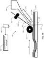
- FIG. 2D is a diagram of an alternative embodiment of an apparatus utilizing a molten polymer dispensing system.
- FIG. 4 is a flowchart indicating process steps for embodiments of the present invention.
- Disclosed embodiments provide automated fiber placement techniques for fabrication of parts made from composite materials. Tape plies are wound around a mandrel while a polymer is dispensed on a tape ply shortly before compaction. A bead monitoring system monitors the size and placement of the bead on the tape ply and feeds back information to various process control systems to maintain an optimal bead size.
- FIG. 1 shows a system block diagram in accordance with an embodiment of the present invention.
- System 100 comprises a main controller 118 .
- Main controller 118 may be a computer comprising memory 120 , and a processor 122 which is configured to read and write memory 120 .
- the memory 120 may be non-transitory memory, such as flash, ROM, non-volatile static ram, or the like.
- the memory 120 contains instructions that, when executed by processor 122 , control the various subsystems to operate system 100 .
- Main controller 118 may also comprise a display 124 and a user interface 126 for interacting with the system 100 .
- the user interface 126 may comprise a keyboard, touch screen, mouse, or the like.
- the main controller 118 may receive temperature information from temperature monitoring system 116 .
- Temperature monitoring system 116 may comprise a non-contact device for measuring the temperature of the material near the exit point or heat affected zone (HAZ).
- the temperature monitoring system 116 may comprise a thermal imaging system or other suitable means for monitoring the temperature of the material near the HAZ.
- the main controller may in turn adjust the energy output of one or more of the heat sources 110 to maintain a desired temperature range.
- the material dispensing speed which determines the amount of time the material remains within the HAZ, may also be monitored by the main controller 118 by communicating with tape feed controller 114 . If the dispensing speed increases, the energy output may also be increased to compensate for the reduced time the material spends in the HAZ. If the speed increases beyond the point where the temperature can be maintained at the desired temperature, the main controller 118 can communicate with the tape feed controller 114 to reduce the speed.
- the memory 120 of the main controller 118 may be configured to store a plurality of material profiles, or access them from an outside database.
- Each material profile may contain the various parameters for optimal heating, such as a desired energy density profile for that material. For example, some materials may perform better when heated gradually, whereas for other materials, a specific exit temperature range may be more important.
- the profile for each material may contain the preferred energy output settings for each heat source, and may also contain a preferred material dispensing speed. When a user is using a particular material, he may select the corresponding material profile, which then establishes the desired settings of the heat sources 110 and optionally the dispensing speed by communicating with tape feed controller 114 .
- the main controller 118 is further in communication with a polymer dispensing system 115 .
- the polymer dispensing system 115 may include a filament polymer dispensing system, powdered polymer dispensing system, and/or a molten polymer dispensing system.
- HZ heat affected zone
- a bead monitoring system 117 substantially continuously or periodically monitors the size, volume, and/or location of dispensed polymer material on a ply of fiber tape.
- the dispensed polymer material forms a molten or liquid bead. In other embodiments, such as with powder dispensing, the powder becomes a bead after compaction with the roller.
- the term “bead” and “dispensed polymer material” may be used interchangeably.
- the bead monitoring system 117 may monitor the width of dispensed polymer material, regardless of if the dispensed polymer material is in liquid form, solid form, power form, or other suitable form.
- the bead size is selected such that, upon compaction, it extends substantially to the width of the ply of tape, but not beyond it.
- the word “substantially” herein is interpreted to mean “to a significant extent”, but that minor variations may be present.
- the bead monitoring system 117 feeds back information to the main controller 118 .
- the main controller 118 can adjust the rate at which the polymer is dispensed from the polymer dispensing system 115 .
- the main controller 118 can adjust the temperature of the HAZ by controlling the heat source(s) 110 .
- the main controller 118 can adjust the tape speed by controlling the tape feed controller 114 .
- the main controller 118 can adjust the compaction pressure by controlling the tape feed controller 114 .
- multiple process parameters can be adjusted to maintain a consistent bead size.
- FIG. 2A is a diagram of an apparatus 200 utilizing a filament polymer dispensing system.
- Fiber tapes are placed over a tool (mandrel) 212 to form a desired component shape.
- tape 214 and tape 216 have been previously applied.
- Tape 208 is currently being applied.
- a heat source 204 applies heat to the currently applied tape 208 as it is dispensed from tape feed 206 , and also applies heat to the previously applied tape 216 .
- the heat source 204 may be a laser, hot gas torch, or any other suitable device.
- the area where heat is applied is referred to as a Heat Affected Zone (HAZ) 202 .
- a filament polymer dispensing system 205 dispenses a polymer filament 231 .
- the polymer filament 231 is dispensed from filament supply 207 and melts as it enters the HAZ 202 .
- the polymer filament 231 forms a bead on the previously applied tape.
- the HAZ raises the currently applied tape 208 , polymer, and the previously applied tape 216 to a temperature suitable to affect a bond between the layers.
- Currently applied tape 208 is then compacted to (pressed against) previously applied tape 216 with the polymer 231 disposed between them, by compaction roller 210 , causing a strong bond to form between tape ply 208 and tape ply 216 .
- the filament comprises a PEEK filament.
- the tape shrinks as it cools due to its Coefficient of Thermal Expansion (CTE) at varying rates depending on factors, non-limiting examples of which include the type of fiber, matrix, and the direction (e.g., fiber direction or cross-fiber direction) in which shrinkage is measured.
- CTE Coefficient of Thermal Expansion
- the currently applied tape 208 , heat source 204 , and associated tape supply mechanism travel in direction D to apply the tape. In some embodiments, this motion may be repeated as necessary or desirable to build up a composite shape.
- One way to achieve a small HAZ 202 is to use a high intensity energy source such as a laser. If the laser energy is of a wavelength that is absorbed by the polymer (such as CO2 lasers at 10.6 ⁇ m), then the high intensities that are needed for high process rates tend to vaporize or otherwise damage the polymer on the surface resulting in poor bond quality. Therefore, with the non-uniform fiber distribution and/or surfaces of the prior art approaches, uneven heating and poor bond quality can result. If the laser energy is of a wavelength to which the polymer is transparent (such as, for example, diode lasers or fiber lasers at 1060 nm) then an absorbing material can be used to further enhance the HAZ.
- a high intensity energy source such as a laser.
- Image acquisition device (e.g. camera) 232 is disposed to monitor the bead produced by filament 231 .
- Image acquisition device 232 is coupled to a computer vision system 263 to perform automated bead size and/or location measurements.
- the computer vision system 263 is at least one computing device, having a processor and memory.
- the memory may store instructions, that when executed by the computing device, perform the bead size and/or location measurements.
- image acquisition device 232 may be a video camera, still camera, or other digital image acquisition device.
- the image acquisition device may be a visible light camera, infrared light camera, X-ray camera, or other suitable imaging device. While one camera is shown in FIG. 2A , in embodiments, multiple cameras may be used to monitor the bead size from a variety of angles and vantage points (as depicted in FIG. 2D ).
- FIG. 2B is a diagram of an apparatus 201 utilizing a powdered polymer dispensing system.
- Apparatus 201 is similar to apparatus 200 of FIG. 2A , except that instead of a filament polymer dispensing system, a powdered polymer dispensing system 237 is used to dispense powdered polymer 247 .
- the powdered polymer dispensing system 237 may be a vibratory dispensing system, corkscrew dispensing system, conveyor belt dispensing system, or other suitable powdered polymer dispensing system.
- a hopper 230 may store a supply of powdered polymer for dispensing.
- the powdered polymer is dispensed at or near the HAZ 202 such that it quickly becomes liquid and forms a bead on ply 216 .
- the powdered polymer is comprised of particles having a size ranging from 10 microns to 75 microns.
- FIG. 2C is a diagram of an apparatus 203 utilizing a molten polymer dispensing system.
- Apparatus 203 is similar to apparatus 200 of FIG. 2A , except that instead of a filament polymer dispensing system, molten polymer dispensing system 241 is used to dispense polymer 251 .
- the polymer 251 may be dispensed at some distance away from the HAZ 202 , which simplifies design considerations of the apparatus.
- the polymer 251 may be dispensed at a distance from the HAZ 202 ranging from five centimeters to ten centimeters. This is an example, and not meant to be limiting. Other suitable distances are included within the scope of the invention.
- FIG. 2D is a diagram of an alternative embodiment of an apparatus utilizing a molten polymer dispensing system.
- FIG. 2D shows a view from the vantage point of arrow A of FIG. 2C .
- multiple image acquisition devices are depicted.
- a first image acquisition device 232 may be oriented to acquire a top-down view of the polymer bead 304 .
- a second image acquisition device 259 may be oriented horizontally with respect to polymer bead 304 , such that it can measure a height H of polymer bead 304 .
- the height, bead width, and overall bead volume can be important parameters in a thermoplastic composite application.
- a non-contact temperature probe 257 may be oriented to monitor a temperature of the polymer bead 304 as it is being applied to a surface of tape ply 216 .
- the non-contact temperature probe includes an infrared (IR) sensor.
- IR infrared
- the information acquired by the probe 257 and the image acquisition devices (cameras) 232 and 259 may be sent to the computer vision system 263 , temperature monitoring system 116 , polymer dispensing system 115 , bead monitoring system 117 , and/or tape feed controller 114 .
- FIG. 3 shows an example 300 of a polymer bead in accordance with embodiments of the present invention in a top-down view.
- a tape ply 302 has a polymer material (bead) 304 dispensed on it.
- Camera 232 monitors the size of bead 304 .
- camera 232 may be coupled to a computer vision system that performs an edge detection process to identify edge 306 of the bead 304 .
- the system determines a bead width W 2 , and a margin distance D.
- the margin distance D is a distance from the edge of the tape ply 302 to the closest point of the bead 304 .
- the tape ply has a width W 1 where W 1 >W 2 .
- a volume of the bead may also be computed, based on W 2 , and H ( FIG. 2D ). In some embodiments, the volume is approximated as: H ⁇ W2 ⁇ /2
- the computer vision system may perform a gradient analysis to determine the edge boundary.
- the computer vision system may utilize a color analysis to identify the location of the polymer bead against the tape ply.
- the value of each pixel in a gradient matrix represents the value of the intensity gradient in a given pixel location.
- the gradient size is calculated as the Pythagorean sum of the difference between the intensity of a given pixel and its close neighbors, and a gradient map is computed.
- the gradient map can be effective for edge detection since the edges of objects and patterns in images are usually characterized by a strong intensity change. Therefore, edges of the polymer bead in acquired images can be found by locating image areas with a large gradient.
- an edge image is computed as a binary matrix in which each pixel (cell) can have one of two values: 0 (black) or 1 (white). Pixels with values of 1 correspond to edges in the image. Edges in the image are usually characterized by a sharp change in intensity. Therefore, a simple method for the identification of edges is using all pixels in which the intensity gradient size exceeds some threshold value. In other embodiments, a more sophisticated method such as a Canny edge detector may be used for determining the edge of the polymer bead.
- the compacted width of the material 304 is substantially equal to W 1 , and thus, excess material does not seep out from the plies. This is an important aspect of successful fabrication of composite parts, as it reduces waste by eliminating excess polymer material, while providing maximum contact area of the polymer material, contributing to the strength of composite parts formed using disclosed techniques.
- FIG. 4 is a flowchart 400 indicating process steps for embodiments of the present invention.
- a polymer is dispensed at or near the HAZ of an automated fiber placement apparatus.
- the bead size of the polymer is monitored.
- one or more process parameters may be periodically adjusted to maintain a consistent bead size and/or location. These include adjusting a dispense rate of the polymer at process step 454 , adjusting a tape speed at process step 456 , adjusting a HAZ temperature at process step 458 , and/or adjusting a compaction pressure at process step 460 .
- the process then continues back to process step 452 for continuous monitoring of the bead during placement of tape plies.
- embodiments include continuously monitoring the bead width and adjusting a process parameter to maintain a constant bead width.
- K 1 , K 2 , K 3 , and K 4 are constants
- D is the dispense rate of the polymer
- S is the tape speed
- T is the temperature of the HAZ
- the constants may be tuned empirically for a given application.
- This formula is an example, and any suitable formula is included within the scope of the invention.
- embodiments of the present invention provide a method and apparatus for automated fiber placement techniques for fabrication of parts made from composite materials.
- Tape plies are wound around a mandrel while a polymer is dispensed on a tape ply shortly before compaction.
- a bead monitoring system monitors the size and placement of the bead on the tape ply and feeds back information to various process control systems to maintain an optimal bead size. This allows fabrication of high-performance components such as aircraft wings and propeller blades in a cost-effective and time-efficient manner.
Landscapes
- Engineering & Computer Science (AREA)
- Chemical & Material Sciences (AREA)
- Manufacturing & Machinery (AREA)
- Materials Engineering (AREA)
- Robotics (AREA)
- Composite Materials (AREA)
- Mechanical Engineering (AREA)
- Moulding By Coating Moulds (AREA)
Abstract
Description
- Melt processable (no cure chemistry, no long soak times, cohesive bonding)
- Extreme toughness/damage tolerance
- Superior solvent and chemical resistance
- No toxicity/hazardous chemical issues
- No refrigeration or out-time considerations
- Recyclable
- Great FST (Fire, Smoke, Toxicity) stability
- Hydrolytic stability—low water absorption
- Stable glass transition temperature (Tg)—even under Hot/Wet conditions
- Good fatigue resistance
- Low coefficient of friction
- High abrasion resistance
H×W2×π/2
B=K 1(D)+K 2(P)+K 3(T)+K 4(S)
Claims (16)
Priority Applications (1)
| Application Number | Priority Date | Filing Date | Title |
|---|---|---|---|
| US15/798,923 US10800113B2 (en) | 2016-12-04 | 2017-10-31 | Bonding for additively manufactured thermoplastic composite structures |
Applications Claiming Priority (2)
| Application Number | Priority Date | Filing Date | Title |
|---|---|---|---|
| US201662429822P | 2016-12-04 | 2016-12-04 | |
| US15/798,923 US10800113B2 (en) | 2016-12-04 | 2017-10-31 | Bonding for additively manufactured thermoplastic composite structures |
Publications (2)
| Publication Number | Publication Date |
|---|---|
| US20180154591A1 US20180154591A1 (en) | 2018-06-07 |
| US10800113B2 true US10800113B2 (en) | 2020-10-13 |
Family
ID=62240000
Family Applications (1)
| Application Number | Title | Priority Date | Filing Date |
|---|---|---|---|
| US15/798,923 Active 2038-09-27 US10800113B2 (en) | 2016-12-04 | 2017-10-31 | Bonding for additively manufactured thermoplastic composite structures |
Country Status (1)
| Country | Link |
|---|---|
| US (1) | US10800113B2 (en) |
Cited By (2)
| Publication number | Priority date | Publication date | Assignee | Title |
|---|---|---|---|---|
| WO2023227662A3 (en) * | 2022-05-25 | 2024-02-01 | Trelleborg Sealing Solutions Germany Gmbh | Method of manufacturing a composite stator sleeve |
| CN119256475A (en) * | 2022-05-25 | 2025-01-03 | 特瑞堡密封系统德国有限公司 | Method for manufacturing a composite stator sleeve |
Families Citing this family (7)
| Publication number | Priority date | Publication date | Assignee | Title |
|---|---|---|---|---|
| GB201518284D0 (en) * | 2015-10-15 | 2015-12-02 | Composite Technology & Applic Ltd | A method of generating a movement profile for a layup procedure |
| US11098691B2 (en) * | 2017-02-03 | 2021-08-24 | General Electric Company | Methods for manufacturing wind turbine rotor blades and components thereof |
| US11167375B2 (en) | 2018-08-10 | 2021-11-09 | The Research Foundation For The State University Of New York | Additive manufacturing processes and additively manufactured products |
| US11597057B2 (en) * | 2019-02-01 | 2023-03-07 | Trelleborg Sealing Solutions Germany Gmbh | Impact forming of thermoplastic composites |
| US12422831B2 (en) | 2022-07-08 | 2025-09-23 | The Boeing Company | Property prediction for unconsolidated composite materials |
| US12566132B2 (en) | 2022-07-08 | 2026-03-03 | The Boeing Company | Real time contaminants identification during composite material manufacturing via non-contact chemical sensing |
| JP2024144252A (en) * | 2023-03-30 | 2024-10-11 | ザ・ボーイング・カンパニー | Real-time inconsistency detection during composite manufacturing |
Citations (2)
| Publication number | Priority date | Publication date | Assignee | Title |
|---|---|---|---|---|
| US20130000838A1 (en) * | 2011-07-01 | 2013-01-03 | Adc Acquisition Company | Fluid medium non-contact consolidation |
| US20140328963A1 (en) * | 2013-03-22 | 2014-11-06 | Markforged, Inc. | Apparatus for fiber reinforced additive manufacturing |
-
2017
- 2017-10-31 US US15/798,923 patent/US10800113B2/en active Active
Patent Citations (2)
| Publication number | Priority date | Publication date | Assignee | Title |
|---|---|---|---|---|
| US20130000838A1 (en) * | 2011-07-01 | 2013-01-03 | Adc Acquisition Company | Fluid medium non-contact consolidation |
| US20140328963A1 (en) * | 2013-03-22 | 2014-11-06 | Markforged, Inc. | Apparatus for fiber reinforced additive manufacturing |
Cited By (5)
| Publication number | Priority date | Publication date | Assignee | Title |
|---|---|---|---|---|
| WO2023227662A3 (en) * | 2022-05-25 | 2024-02-01 | Trelleborg Sealing Solutions Germany Gmbh | Method of manufacturing a composite stator sleeve |
| CN119256475A (en) * | 2022-05-25 | 2025-01-03 | 特瑞堡密封系统德国有限公司 | Method for manufacturing a composite stator sleeve |
| JP2025519044A (en) * | 2022-05-25 | 2025-06-24 | トレレボリ シーリング ソリューションズ ジャーマニー ゲー・エム・ベー・ハー | Manufacturing method of composite stator sleeve |
| CN119256475B (en) * | 2022-05-25 | 2025-08-12 | 特瑞堡密封系统德国有限公司 | Method of manufacturing a composite stator sleeve |
| US12431774B2 (en) | 2022-05-25 | 2025-09-30 | Trelleborg Sealing Solutions Albany, Inc. | Composite stator sleeve |
Also Published As
| Publication number | Publication date |
|---|---|
| US20180154591A1 (en) | 2018-06-07 |
Similar Documents
| Publication | Publication Date | Title |
|---|---|---|
| US10800113B2 (en) | Bonding for additively manufactured thermoplastic composite structures | |
| CN110316399B (en) | Inspection apparatus and method | |
| US10357924B2 (en) | Composite feedstock strips for additive manufacturing and methods of forming thereof | |
| EP3147107B1 (en) | Method of forming composite feedstock strips for additive manufacturing | |
| US11772337B2 (en) | Pultrusion systems that apply lengthwise curvature to composite parts | |
| EP3995297B1 (en) | Method and apparatus for controlling contact of composite tows | |
| AU2020201524B2 (en) | Thermographic inspection for tape layup machines | |
| US20130164498A1 (en) | Thermoplastic composite prepreg for automated fiber placement | |
| EP3219474A1 (en) | Method and device for 3d-printing a fiber reinforced composite component by tape-laying | |
| US20180186099A1 (en) | Forming Composite Features Using Steered Discontinuous Fiber Pre-Preg | |
| JP2017054486A (en) | Automated resin ridge reduction system | |
| US12422831B2 (en) | Property prediction for unconsolidated composite materials | |
| US10717239B2 (en) | Fabrication of gap fillers for composite parts that exhibit varying radii of curvature | |
| JP2024042016A (en) | System and method for fast detection of surface and subsurface FOD and defects | |
| US20260042120A1 (en) | Acquiring images in an additive manufacturing system | |
| Kukwi et al. | Continuous improvement in composite manufacturing: A review of automated fiber placement process evolution and future research prospects | |
| US12566132B2 (en) | Real time contaminants identification during composite material manufacturing via non-contact chemical sensing | |
| Grimsley et al. | In-situ consolidation automated fiber placement of thermoplastic composites for high-rate aircraft manufacturing | |
| EP4134225B1 (en) | Method and system for in-process monitoring of a compaction roller of a composite layup machine | |
| EP3552809B1 (en) | Automated fiber placement end effector with laminar gas cooling jet and infrared image processor for in-situ inspection | |
| CN120606535B (en) | Composite material additive manufacturing method and equipment based on dimensional error compensation | |
| US11597057B2 (en) | Impact forming of thermoplastic composites | |
| Hosseini et al. | Thermal modeling strategies for laser assisted tape winding process | |
| US11141814B2 (en) | Thermographic inspection for tape layup machines | |
| EP4450265B1 (en) | Real time inconsistency detection during composite material manufacturing |
Legal Events
| Date | Code | Title | Description |
|---|---|---|---|
| FEPP | Fee payment procedure |
Free format text: ENTITY STATUS SET TO UNDISCOUNTED (ORIGINAL EVENT CODE: BIG.); ENTITY STATUS OF PATENT OWNER: SMALL ENTITY |
|
| FEPP | Fee payment procedure |
Free format text: ENTITY STATUS SET TO SMALL (ORIGINAL EVENT CODE: SMAL); ENTITY STATUS OF PATENT OWNER: SMALL ENTITY |
|
| AS | Assignment |
Owner name: ADC ACQUISITION COMPANY, NEW YORK Free format text: ASSIGNMENT OF ASSIGNORS INTEREST;ASSIGNORS:HAUBER, DAVID E.;AUGUST, ZACHARY A.;REEL/FRAME:044917/0396 Effective date: 20171214 |
|
| STPP | Information on status: patent application and granting procedure in general |
Free format text: DOCKETED NEW CASE - READY FOR EXAMINATION |
|
| STPP | Information on status: patent application and granting procedure in general |
Free format text: NON FINAL ACTION MAILED |
|
| STPP | Information on status: patent application and granting procedure in general |
Free format text: NOTICE OF ALLOWANCE MAILED -- APPLICATION RECEIVED IN OFFICE OF PUBLICATIONS |
|
| STPP | Information on status: patent application and granting procedure in general |
Free format text: AWAITING TC RESP., ISSUE FEE NOT PAID |
|
| STPP | Information on status: patent application and granting procedure in general |
Free format text: NOTICE OF ALLOWANCE MAILED -- APPLICATION RECEIVED IN OFFICE OF PUBLICATIONS |
|
| STPP | Information on status: patent application and granting procedure in general |
Free format text: PUBLICATIONS -- ISSUE FEE PAYMENT VERIFIED |
|
| STCF | Information on status: patent grant |
Free format text: PATENTED CASE |
|
| AS | Assignment |
Owner name: TRELLEBORG SEALING SOLUTIONS ALBANY, INC., NEW YORK Free format text: CHANGE OF NAME;ASSIGNOR:ADC ACQUISITION COMPANY;REEL/FRAME:058767/0641 Effective date: 20190410 |
|
| AS | Assignment |
Owner name: TRELLEBORG SEALING SOLUTIONS GERMANY GMBH, GERMANY Free format text: ASSIGNMENT OF ASSIGNORS INTEREST;ASSIGNOR:TRELLEBORG SEALING SOLUTIONS ALBANY, INC.;REEL/FRAME:059832/0744 Effective date: 20220502 |
|
| AS | Assignment |
Owner name: TRELLEBORG SEALING SOLUTIONS ALBANY, INC., NEW YORK Free format text: ASSIGNMENT OF ASSIGNORS INTEREST;ASSIGNOR:TRELLEBORG SEALING SOLUTIONS GERMANY GMBH;REEL/FRAME:066309/0506 Effective date: 20240130 |
|
| FEPP | Fee payment procedure |
Free format text: SURCHARGE FOR LATE PAYMENT, SMALL ENTITY (ORIGINAL EVENT CODE: M2554); ENTITY STATUS OF PATENT OWNER: SMALL ENTITY |
|
| MAFP | Maintenance fee payment |
Free format text: PAYMENT OF MAINTENANCE FEE, 4TH YR, SMALL ENTITY (ORIGINAL EVENT CODE: M2551); ENTITY STATUS OF PATENT OWNER: SMALL ENTITY Year of fee payment: 4 |
|
| FEPP | Fee payment procedure |
Free format text: ENTITY STATUS SET TO UNDISCOUNTED (ORIGINAL EVENT CODE: BIG.); ENTITY STATUS OF PATENT OWNER: LARGE ENTITY |