US10798403B2 - Prediction image generation device, video decoding device, and video coding device - Google Patents
Prediction image generation device, video decoding device, and video coding device Download PDFInfo
- Publication number
- US10798403B2 US10798403B2 US16/073,508 US201716073508A US10798403B2 US 10798403 B2 US10798403 B2 US 10798403B2 US 201716073508 A US201716073508 A US 201716073508A US 10798403 B2 US10798403 B2 US 10798403B2
- Authority
- US
- United States
- Prior art keywords
- prediction
- point
- unit
- motion vector
- vector
- Prior art date
- Legal status (The legal status is an assumption and is not a legal conclusion. Google has not performed a legal analysis and makes no representation as to the accuracy of the status listed.)
- Active, expires
Links
- 239000013598 vector Substances 0.000 claims abstract description 798
- 238000009795 derivation Methods 0.000 abstract description 258
- PXFBZOLANLWPMH-UHFFFAOYSA-N 16-Epiaffinine Natural products C1C(C2=CC=CC=C2N2)=C2C(=O)CC2C(=CC)CN(C)C1C2CO PXFBZOLANLWPMH-UHFFFAOYSA-N 0.000 description 199
- 230000015654 memory Effects 0.000 description 92
- 238000012545 processing Methods 0.000 description 86
- 238000005192 partition Methods 0.000 description 75
- 238000010586 diagram Methods 0.000 description 57
- 239000010410 layer Substances 0.000 description 37
- 230000005540 biological transmission Effects 0.000 description 33
- 238000000034 method Methods 0.000 description 33
- 238000012986 modification Methods 0.000 description 20
- 230000004048 modification Effects 0.000 description 20
- 238000000638 solvent extraction Methods 0.000 description 18
- 230000014509 gene expression Effects 0.000 description 16
- 238000004891 communication Methods 0.000 description 14
- 230000006854 communication Effects 0.000 description 14
- 238000013139 quantization Methods 0.000 description 14
- 230000010354 integration Effects 0.000 description 12
- 230000003247 decreasing effect Effects 0.000 description 10
- 238000006073 displacement reaction Methods 0.000 description 10
- 230000006870 function Effects 0.000 description 9
- 230000002123 temporal effect Effects 0.000 description 8
- 238000013519 translation Methods 0.000 description 8
- 238000010606 normalization Methods 0.000 description 5
- 238000010200 validation analysis Methods 0.000 description 5
- 238000005516 engineering process Methods 0.000 description 4
- 238000001914 filtration Methods 0.000 description 4
- 239000011159 matrix material Substances 0.000 description 4
- 238000004364 calculation method Methods 0.000 description 3
- 230000007423 decrease Effects 0.000 description 3
- 230000000694 effects Effects 0.000 description 3
- 239000000284 extract Substances 0.000 description 3
- NRNCYVBFPDDJNE-UHFFFAOYSA-N pemoline Chemical compound O1C(N)=NC(=O)C1C1=CC=CC=C1 NRNCYVBFPDDJNE-UHFFFAOYSA-N 0.000 description 3
- 208000034188 Stiff person spectrum disease Diseases 0.000 description 2
- 229920010524 Syndiotactic polystyrene Polymers 0.000 description 2
- 230000007175 bidirectional communication Effects 0.000 description 2
- 238000005401 electroluminescence Methods 0.000 description 2
- 208000012112 ischiocoxopodopatellar syndrome Diseases 0.000 description 2
- 238000012886 linear function Methods 0.000 description 2
- 230000003287 optical effect Effects 0.000 description 2
- 229920000069 polyphenylene sulfide Polymers 0.000 description 2
- 239000004065 semiconductor Substances 0.000 description 2
- 239000002356 single layer Substances 0.000 description 2
- 238000002490 spark plasma sintering Methods 0.000 description 2
- 241000023320 Luma <angiosperm> Species 0.000 description 1
- 241001025261 Neoraja caerulea Species 0.000 description 1
- 230000003044 adaptive effect Effects 0.000 description 1
- 238000004458 analytical method Methods 0.000 description 1
- 230000002457 bidirectional effect Effects 0.000 description 1
- 238000006243 chemical reaction Methods 0.000 description 1
- 230000000536 complexating effect Effects 0.000 description 1
- 238000013461 design Methods 0.000 description 1
- 230000009189 diving Effects 0.000 description 1
- 239000011229 interlayer Substances 0.000 description 1
- 238000011835 investigation Methods 0.000 description 1
- 239000004973 liquid crystal related substance Substances 0.000 description 1
- 230000007774 longterm Effects 0.000 description 1
- OSWPMRLSEDHDFF-UHFFFAOYSA-N methyl salicylate Chemical compound COC(=O)C1=CC=CC=C1O OSWPMRLSEDHDFF-UHFFFAOYSA-N 0.000 description 1
- 239000000203 mixture Substances 0.000 description 1
- 238000010295 mobile communication Methods 0.000 description 1
- 230000002093 peripheral effect Effects 0.000 description 1
- 239000013643 reference control Substances 0.000 description 1
- 239000007787 solid Substances 0.000 description 1
- 230000000153 supplemental effect Effects 0.000 description 1
Images


Classifications
-
- H—ELECTRICITY
- H04—ELECTRIC COMMUNICATION TECHNIQUE
- H04N—PICTORIAL COMMUNICATION, e.g. TELEVISION
- H04N19/00—Methods or arrangements for coding, decoding, compressing or decompressing digital video signals
- H04N19/50—Methods or arrangements for coding, decoding, compressing or decompressing digital video signals using predictive coding
- H04N19/503—Methods or arrangements for coding, decoding, compressing or decompressing digital video signals using predictive coding involving temporal prediction
- H04N19/51—Motion estimation or motion compensation
- H04N19/513—Processing of motion vectors
- H04N19/517—Processing of motion vectors by encoding
- H04N19/52—Processing of motion vectors by encoding by predictive encoding
-
- H—ELECTRICITY
- H04—ELECTRIC COMMUNICATION TECHNIQUE
- H04N—PICTORIAL COMMUNICATION, e.g. TELEVISION
- H04N19/00—Methods or arrangements for coding, decoding, compressing or decompressing digital video signals
- H04N19/70—Methods or arrangements for coding, decoding, compressing or decompressing digital video signals characterised by syntax aspects related to video coding, e.g. related to compression standards
Definitions
- An embodiment of the disclosure relates to a prediction image generation device, a video decoding device, and a video coding device.
- a video coding scheme examples include schemes proposed in H.264/MPEG-4. AVC or High-Efficiency Video Coding (HEVC).
- AVC High-Efficiency Video Coding
- images (pictures) constituting a video are managed by a hierarchical structure including slices obtained by diving the images, units of coding (also referred to as Coding Units) obtained by dividing the slices, and prediction units (PUs) and transform units (TUs) which are blocks obtained by dividing the coding units, and each block is coded/decoded.
- units of coding also referred to as Coding Units
- PUs prediction units
- TUs transform units
- an input image is coded/decoded to obtain a local decoded image, based on which local decoded image a prediction image is generated, the prediction image is subtracted from the input image (original image) to obtain a prediction residual (also referred to as a “difference image” or a “residual image”), and the prediction residual is coded.
- a prediction residual also referred to as a “difference image” or a “residual image”
- Examples of a method for generating a prediction image include inter-prediction, and intra-prediction.
- NPL 1 discloses a technology that, in the intra-prediction, a “simplified affine” motion model is applied which is higher in a degree of freedom than a translational motion model to represent rotation and zoom of a prediction image.
- NPL 1 in a case that a motion vector of a decoding target block is derived using the affine prediction, two points having the same X-coordinate (horizontal coordinate) or Y-coordinate (vertical coordinate) which is located on a corner of the decoding target block are merely used as control points which are referred to for deriving the affine prediction motion vector. Therefore, the wider interval between the points used as the control points, the more accurately the motion vector can be derived with a higher probability. For this reason, there is a limitation to a case that the interval between the points used as the control points is equal to a length of one side of the decoding target block, which has been a first problem.
- the derivation of the motion vector of the decoding target block using the affine prediction is made through processing in two steps, first, a motion vector of a representative point (block control point) on a decoding target block is derived from a motion vector of a prediction unit of a reference target candidate, and then, a motion vector of each sub-block of the decoding target block is derived from the motion vector of the block control point.
- a precision of the derived motion vector of each sub-block is likely decreased, which has been a second problem.
- a size of a prediction unit containing a reference point which is a point referred to for deriving a motion vector of the control point for the decoding target block is not taken into account, and thus the motion vector of the control point cannot be derived with high precision, which has been a third problem.
- a prediction mode is an AMVP prediction mode in which a difference vector is decoded
- a partition mode is 2N ⁇ 2N
- a flag, pu_affine_enable_flag, indicating whether to adopt the affine prediction is decoded. Therefore, even in the case of 2N ⁇ 2N that the difference vector needs to be decoded only one time (a set of an X component and a Y component), two times decoding has been required only in the case that the affine prediction is used. This requires, in the processing for decoding the difference vector, a special loop process only in a case of affine transform, complexing the processing, which has been a fourth problem.
- An embodiment of the disclosure attempts to solve any one of the above first to fourth problems, and has an object to provide an image decoding device, an image coding device, and a prediction image generation device which can suppress a code amount from increasing and generate a prediction image with higher precision.
- a prediction image generation device for generating a prediction image used to code or decode a video
- the prediction image generation device including a prediction vector compute unit, and a prediction image generation unit
- the prediction vector compute unit computes a motion vector of each of multiple prediction blocks which are included in a target block by referring to motion vectors at multiple first control points including two points at an interval longer than one side of the target block
- the prediction image generation unit refers to the motion vector of each prediction block to generate the prediction image.
- a prediction image generation device for generating a prediction image used to code or decode a video
- the prediction image generation device including a prediction vector compute unit, and a prediction image generation unit
- the prediction vector compute unit computes a motion vector of each of multiple prediction blocks which are included in a target block by referring to motion vectors at multiple first control points configured inside a prediction block which neighbors to the target block or shares a vertex with the target block, and a relative coordinate from any of the multiple first control points
- the prediction image generation unit refers to the motion vector of each prediction block to generate the prediction image.
- a prediction image generation device for generating a prediction image used to code or decode a video
- the prediction image generation device including a prediction vector compute unit, and a prediction image generation unit
- the prediction vector compute unit refers to motion vectors at multiple reference points inside a block containing a prediction block which shares a lower left vertex of a target block and neighbors to a left side of the target block, and a relative coordinate from any of the multiple reference points to compute motion vectors at multiple first control points, and computes a motion vector of each of multiple prediction blocks which are included in the target block by referring to the motion vectors at the multiple first control points
- the prediction image generation unit refers to the motion vector of each prediction block to generate the prediction image.
- a prediction image generation device for generating a prediction image used to code or decode a video
- the prediction image generation device including a prediction vector compute unit, and a prediction image generation unit
- the prediction vector compute unit computes a motion vector of each of multiple prediction blocks which are included in a target block by referring to motion vectors at multiple first control points configured at vertexes of the target block
- the prediction image generation unit refers to the motion vector of each prediction block to generate a prediction image.
- the prediction vector compute unit refers to, as the motion vectors at the multiple first control points, the motion vectors at the upper right vertex and the lower left vertex of the target block, and in a case that the motion vectors at both the upper right vertex and the lower left vertex of the target block does not exist as effective motion vectors, the prediction vector compute unit refers to, as the motion vectors at the multiple first control points, a vector existing as an effective motion vector among the motion vectors at the upper right vertex and the lower left vertex, and the motion vector at the upper left vertex of the target block as the motion vector at the first control point.
- a video decoding device including a prediction image generation unit supporting affine prediction, wherein a flag specifying whether or not the affine prediction is used is decoded in the case that a merge flag merge_flag specifies that merge processing is not performed and that a syntax, part_mode, indicating a partition mode is N ⁇ 2N or 2N ⁇ N.
- a video decoding device including a prediction image generation unit supporting affine prediction, wherein a flag specifying whether or not the affine prediction is used is decoded in the case that a merge flag merge_flag specifies that merge processing is not performed and that a syntax, part_mode, indicating a partition mode is other than 2N ⁇ 2N, and the partition mode is set to N ⁇ 2N in the case that the flag specifies that the affine prediction is used.
- a video decoding device including a prediction image generation unit supporting affine prediction, wherein in the case that a merge flag merge_flag specifies that merge processing is not performed and that a syntax, part_mode, indicating a partition mode is decoded, some of bits of binarization for the part_mode indicate a partition mode, and the partition mode indicates two modes in which the number of partitions is 2 (2N ⁇ N or N ⁇ 2N), a flag specifying whether or not the affine prediction is used is included as one of other bits of the binarization for the syntax indicating the partition mode.
- a motion vector of a control point for deriving a motion vector of a target block and a motion vector of a sub-block derived from the control point, allowing a prediction image with higher precision to be generated. Further, coding efficiencies of an image coding device and image decoding device can be improved.
- FIGS. 1A to 1F are diagrams illustrating a hierarchical structure of data of a coded stream according to the present embodiment.
- FIGS. 2A to 2H are diagrams illustrating patterns for a PU partition mode.
- FIGS. 2A to 2H respectively illustrate partition shapes in cases that the PU partition mode is 2N ⁇ 2N, 2N ⁇ N, 2N ⁇ nU, 2N ⁇ nD, N ⁇ 2N, nL ⁇ 2N, nR ⁇ 2N, and N ⁇ N.
- FIG. 3 is a conceptual diagram illustrating an example of a reference picture list.
- FIG. 4 is a conceptual diagram illustrating an example of reference pictures.
- FIG. 5 is a schematic diagram illustrating a configuration of an image decoding device according to the present embodiment.
- FIG. 6 is a schematic diagram illustrating a configuration of an inter-prediction parameter decoding unit according to the present embodiment.
- FIG. 7 is a schematic diagram illustrating a configuration of a merge prediction parameter derivation unit according to the present embodiment.
- FIG. 8 is a schematic diagram illustrating a configuration of an AMVP prediction parameter derivation unit according to the present embodiment.
- FIG. 9 is a conceptual diagram illustrating an example of vector candidates.
- FIG. 10 is a schematic diagram illustrating a configuration of an inter-prediction parameter decoding control unit according to the present embodiment.
- FIG. 11 is a schematic diagram illustrating a configuration of an inter-prediction image generation unit according to the present embodiment.
- FIG. 12 is a block diagram illustrating a configuration of an image coding device according to the present embodiment.
- FIG. 13 is a schematic diagram illustrating a configuration of an inter-prediction parameter coding unit according to the present embodiment.
- FIG. 14 is a schematic diagram illustrating a configuration of an image transmission system according to an embodiment of the disclosure.
- FIGS. 15A to 15C are diagrams illustrating motion vectors which may be used in a motion model, in which FIG. 15A illustrates a translation vector, FIG. 15B illustrates a zoom vector, and FIG. 15C illustrates a rotation vector.
- FIG. 16A illustrates an equation representing in a form of a matrix a general expression which expresses a motion vector at a point Vi (MVi_xi, MVi_yi), and
- FIG. 16B illustrates a general solution obtained by solving the equation in FIG. 16A in terms of a zoom vector and rotation vector.
- FIGS. 17A to 17C illustrate general solutions derived in a pattern in which a calculator needs a less amount of calculation in deriving a general solution illustrated in FIG. 17B .
- FIG. 18A illustrates a diagram illustrating motion vectors at points in an example of a case that a zoom center is a center position of a block
- FIG. 18B illustrates a diagram illustrating motion vectors at points in an example of a case that a rotation center is a center position of a block.
- FIGS. 19A to 19C are diagrams illustrating examples of a location of a prediction unit used for deriving a motion vector of a control point in an AMVP mode and merge mode.
- FIG. 20 is a diagram illustrating a corner containing a control point V 0 of a block (width W, height H) whose motion vector is to be predicted.
- FIG. 21 is a diagram illustrating an example in which a motion vector of each of 16 sub-blocks which constitute a block (width W) whose motion vector is to be predicted is derived from control points V 0 and V 1 .
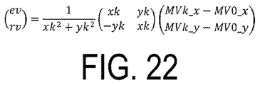
- FIG. 22 is a general expression for deriving a motion vector of coordinates (xi, yi) from a location and motion vector of an arbitrary point Vk.
- FIGS. 23A and 23B illustrate a case that a point V 1 and a point V 2 are used
- FIGS. 23C and 23D illustrate a case that a point V 0 and a point V 3 are used.
- FIG. 24 is a diagram illustrating two reference candidate points having the same X-coordinate or Y-coordinate.
- FIG. 25 is a diagram illustrating an example of a case that a center point of a prediction unit neighboring to a decoding target block is a reference candidate point.
- FIG. 26 is a diagram illustrating an example in which a point located outside a decoding target block is used as a control point.
- FIG. 27 is a diagram illustrating an example in which a reference candidate point specified by an index is used as a control point.
- FIG. 28 a diagram illustrating an example of a case that a center point of a prediction unit neighboring to a decoding target block is a point used as the control point.
- FIG. 29 is a diagram illustrating an example in which a reference candidate point used as a control point is changed based on a size of a prediction unit.
- FIG. 30 is a diagram illustrating an example in which motion vectors of control points for a decoding target block is derived from three points contained in a block containing a prediction unit A.
- FIGS. 31A and 31B are examples of a syntax for a coding unit.
- FIG. 32 is an example of a syntax for a prediction unit.
- FIG. 33 is an example of a syntax for coding of a difference vector.
- FIG. 34 is an example of a syntax for a coding unit.
- FIG. 35 is another example of a syntax for a prediction unit.
- FIG. 36 is an example of a binarization table for switching validation/invalidation of AMP depending on a value of a PU affine application flag, a partition type, and a CU size.
- FIG. 37 is another example of a syntax for a prediction unit.
- FIG. 38 is an example of another binarization table for switching validation/invalidation of AMP depending on a value of a PU affine application flag, a partition type, and a CU size.
- FIGS. 39A and 39B are diagrams illustrating configurations of a transmission device equipped with the above image coding device and a reception device equipped with the above image decoding device.
- FIG. 39A illustrates the transmission device equipped with the image coding device
- FIG. 39B illustrates the reception device equipped with the image decoding device.
- FIGS. 40A and 40B are diagrams illustrating configurations of a recording device equipped with the above image coding device and a reproducing device equipped with the above image decoding device.
- FIG. 40A illustrates the recording device equipped with the image coding device
- FIG. 40B illustrates the reproducing device equipped with the image decoding device.
- FIG. 14 is a schematic diagram illustrating a configuration of an image transmission system 1 according to the present embodiment.
- the image transmission system 1 is a system in which a code obtained by coding a coding target image is transmitted and the image obtained by decoding the transmitted code is displayed.
- the image transmission system 1 is configured to include an image coding device 11 (video coding device), a network 21 , an image decoding device 31 (video decoding device), and an image display device 41 .
- Signals T representing an image of a single layer or multiple layers are input to the image coding device 11 .
- a layer is a concept used to distinguish multiple pictures in a case that a certain time period is constituted by one or more pictures.
- scalable coding applies in a case that the same picture is coded in multiple layers which are different in an image quality or resolution
- view scalable coding applies in a case that pictures different in a viewpoint are coded in multiple layers.
- prediction is performed between pictures of multiple layers (inter-layer prediction, inter-view prediction)
- the coding efficiency is highly improved.
- prediction is not performed (simulcast)
- the coded data can be collected.
- the image coding device 11 and the image decoding device 31 may adopt a single layer image, or may perform an arbitrary combination of the scalable coding and the view scalable coding.
- the network 21 transmits a coded stream Te generated by the image coding device 11 to the image decoding device 31 .
- the network 21 includes the Internet, a Wide Area Network (WAN), or a Local Area Network (LAN), or a combination thereof.
- the network 21 is not necessarily limited to a bidirectional communication network, but may be a unidirectional or bidirectional communication network transmitting broadcast waves such as digital terrestrial broadcasting and satellite broadcasting.
- the network 21 may be substituted by a storage medium in which the coded stream Te is recorded such as a Digital Versatile Disc (DVD) and a Blue-ray Disc (BD).
- DVD Digital Versatile Disc
- BD Blue-ray Disc
- the image decoding device 31 decodes each coded stream Te transmitted by the network 21 , and generates one or multiple decoded layer images Td (decoded viewpoint images Td).
- the image display device 41 displays all or some of one or multiple decoded layer images Td generated by the image decoding device 31 .
- a three-dimensional image (stereoscopic image) or free-viewpoint image is displayed, and in the case of displaying some, a two-dimensional image is displayed.
- the image display device 41 includes a display device, for example, a liquid crystal display and an organic Electro-luminescence (EL) display.
- the image decoding device 31 and the image display device 41 display an enhancement layer image which is higher in an image quality in a case of having high processing capability, and display a base layer image for which processing capability and display capability are required not so much high as the enhancement layer in a case of having only lower processing capability.
- the image coding device 11 and the image decoding device 31 Before describing in detail, the image coding device 11 and the image decoding device 31 according to the present embodiment, a description is given of a data structure of the coded stream Te which is generated by the image coding device 11 and decoded by the image decoding device 31 .
- FIGS. 1A to 1F are diagrams illustrating a hierarchical structure of data in the coded stream Te.
- the coded stream Te exemplarily contains a sequence and multiple pictures constituting the sequence.
- FIGS. 1A to 1F are diagrams respectively illustrating a sequence layer specifying a sequence SEQ, a picture layer specifying a picture PICT, a slice layer specifying a slice S, a slice data layer specifying slice data, a coded tree layer specifying a coded tree unit included in the slice data, and a coded unit layer specifying a Coding Unit (CU) included in the coding tree.
- CU Coding Unit
- the sequence layer specifies a set of data to which the image decoding device 31 refers in order to decode the sequence SEQ to be processed (hereinafter, also referred to as a target sequence).
- the sequence SEQ contains, as illustrated in FIG. 1A , a Video Parameter Set, a Sequence Parameter Set (SPS), a Picture Parameter Set (PPS), a picture PICT, and Supplemental Enhancement Information (SEI).
- SPS Sequence Parameter Set
- PPS Picture Parameter Set
- SEI Supplemental Enhancement Information
- a value following “#” indicates a layer ID.
- FIGS. 1A to 1F illustrate an example in which there is coded data of #0 and #1, that is, a layer 0 and a layer 1, but types of layer and the number of layers are not limited thereto.
- the video parameter set VPS specifies, for a video configured with multiple layers, set of coding parameters common to multiple videos and a set of coding parameters associated with multiple layers and individual layers contained in the video.
- the sequence parameter set SPS specifies a set of coding parameters to which the image decoding device 31 refers in order to decode the target sequence. For example, a width and height of a picture are specified. There may be multiple SPSs. In this case, any of multiple SPSs is selected from the PPS.
- the picture parameter set PPS specifies a set of coding parameters to which the image decoding device 31 refers in order to decode pictures in the target sequence.
- the PPS includes a reference value of a quantization width (pic_init_qp_minus26) used to decode the picture and a flag indicating that a weighted prediction is applied (weighted_pred_flag).
- a quantization width (pic_init_qp_minus26) used to decode the picture and a flag indicating that a weighted prediction is applied.
- weighted_pred_flag a flag indicating that a weighted prediction is applied
- the picture layer specifies a set of data to which the image decoding device 31 refers in order to decode a picture PICT to be processed (hereinafter, also referred to as a target picture).
- the picture PICT contains slices S 0 to SNS ⁇ 1 (NS represents the total number of slices contained in the picture PICT) as illustrated in FIG. 1B .
- the slices S 0 to SNS ⁇ 1 may be expressed with their suffixes omitted in a case of being not necessary to be distinguished from each other. The same holds for other data with a suffix which is contained in the coded stream Te described below.
- the slice layer specifies a set of data to which the image decoding device 31 refers in order to decode a slice S to be processed (also referred to as a target slice).
- the slice S contains a slice header SH and slice data SDATA, as illustrated in FIG. 1C .
- the slice header SH contains a coding parameter group to which the image decoding device 31 refers in order to determine a method of decoding a target slice.
- Slice type specifying information specifying a slice type (slice_type) is an example of the coding parameter contained in the slice header SH.
- Examples of the slice type specifiable by the slice type specifying information include (1) I slice that is coded using intra prediction only, (2) P slice that is coded using unidirectional prediction or intra-prediction, and (3) B slice that is coded using unidirectional prediction, bidirectional prediction, or intra prediction.
- the slice header SH may include reference to the picture parameter set PPS (pic_parameter_set_id) which is contained in the above sequence layer.
- the slice data layer specifies a set of data to which the image decoding device 31 refers in order to decode slice data SDATA to be processed.
- the slice data SDATA contains a Coded Tree Block (CTB) as illustrated in FIG. 1D .
- CTB is a block having a fixed size (e.g., 64 ⁇ 64) constituting a slice, and may be also referred to as a Largest Cording Unit (LCU) or a Coded Tree Unit (CTU).
- LCU Largest Cording Unit
- CTU Coded Tree Unit
- the coded tree layer specifies a set of data to which the image decoding device 31 refers in order to decode a coded tree block to be processed as illustrated in FIG. 1E .
- the coded tree block is partitioned by recursive quadtree partitioning.
- a node of a tree structure obtained by the recursive quadtree partitioning is called a coding tree.
- An intermediate node of the quadtree is a Coded Quad Tree (CQT) and the coded tree block itself is specified as a top CQT.
- the CQT contains a split flag (split_flag), and is partitioned into four CQTs in a case that split_flag is 1.
- the CQT is not partitioned and has one Coded Unit (CU) as a node.
- the coded unit CU is a terminal node of the coded tree layer and is not partitioned any further in this layer.
- the coding unit CU is a basic unit for coding processing.
- a size of the coded tree block CTB is 64 ⁇ 64 pixel
- a size of the coded unit may be any of 64 ⁇ 64 pixel, 32 ⁇ 32 pixel, 16 ⁇ 16 pixel, and 8 ⁇ 8 pixel.
- the coded unit layer specifies a set of data to which the image decoding device 31 refers in order to decode a coded unit to be processed, as illustrated in FIG. 1F .
- the coding unit includes a coding tree, a prediction tree, a transform tree, and a CU header CUF.
- the coding tree specifies a split flag, a division pattern, a prediction mode, and the like.
- the prediction tree specifies prediction information (reference picture index, motion vector, and the like) of each of prediction blocks which are obtained by partitioning the coded unit into one or multiple pieces.
- the prediction block/blocks is/are one or multiple non-overlapping areas which constitute the coding unit.
- the prediction tree includes one or multiple prediction blocks which are obtained by the above partitioning.
- a unit of prediction obtained by further partitioning the prediction block is called a “sub-block”.
- the sub-block (prediction block) is configured with one or multiples pixel. In a case that a size of the prediction block is equal to a size of the sub-block, the number of sub-blocks in the prediction block is one.
- the prediction block is partitioned into the sub-blocks. For example, in a case that a size of the prediction block is 8 ⁇ 8 and a size of the sub-block is 4 ⁇ 4, the prediction block is partitioned horizontally into two and vertically into two to be partitioned into four sub-blocks.
- Prediction processing is performed for each of these prediction blocks (sub-blocks).
- the prediction block as a unit of prediction is also referred to as a prediction unit (PU).
- a type of partition for the prediction tree is roughly classified into two for a case of the intra prediction and a case of the inter prediction.
- the intra prediction is prediction within an identical picture
- the inter prediction is prediction processing performed between pictures different from each other (e.g., between display times, between layer images).
- a partition method includes methods using 2N ⁇ 2N (the same size as the coding unit) and N ⁇ N.
- a partition method includes coding in a PU partition mode (part_mode) in the coded data, and includes mothods using 2N ⁇ 2N (the same size as the coding unit), 2N ⁇ N, 2N ⁇ nU, 2N ⁇ nD, N ⁇ 2N, nL ⁇ 2N, nR ⁇ 2N, and N ⁇ N.
- 2N ⁇ nU indicates that a 2N ⁇ 2N coding unit are partitioned into two areas, 2N ⁇ 0.5N and 2N ⁇ 1.5N, in this order from the upside.
- 2N ⁇ nD indicates that a 2N ⁇ 2N coding unit is partitioned into two areas, 2N ⁇ 1.5N and 2N ⁇ 0.5N, in this order from the upside.
- nL ⁇ 2N indicates that a 2N ⁇ 2N coding unit is partitioned into two areas, 0.5N ⁇ 2N and 1.5N ⁇ 2N, in this order from the left.
- nR ⁇ 2N indicates that a 2N ⁇ 2N coding unit is partitioned into two areas, 1.5N ⁇ 2N and 0.5N ⁇ 1.5N, in this order from the left.
- the number of partitions is any of 1, 2, or 4, and thus, the number of PUs included in the CU is 1 to 4. These PUs are expressed as PU 0 , PU 1 , PU 2 , and PU 3 in this order.
- FIGS. 2A to 2H specifically illustrates a boundary location of PU partitioning in the CU for each partition type.
- FIG. 2A illustrates a PU partition mode for 2N ⁇ 2N in which the CU is not partitioned.
- FIGS. 2B, 2C and 2D illustrate respectively partition shapes in cases that the PU partition modes are 2N ⁇ N, 2N ⁇ nU, and 2N ⁇ nD.
- the partitions in the cases that the PU partition modes are 2N ⁇ N, 2N ⁇ nU, and 2N ⁇ nD are collectively referred to as a horizontally-long partition.
- FIGS. 2E, 2F and 2G illustrate respectively partition shapes in the cases that the PU partition modes are N ⁇ 2N, nL ⁇ 2N, and nR ⁇ 2N.
- the partitions in the case that the PU partition modes are N ⁇ 2N, nL ⁇ 2N, and nR ⁇ 2N are collectively referred to as a vertically-long partition.
- the horizontally-long partition and the vertically-long partition are collectively referred to as a rectangular partition.
- FIG. 2H illustrates a partition shape in a case that the PU partition mode is N ⁇ N.
- the PU partition modes in FIGS. 2A and 2H are also referred to as square partitioning based on their partition shapes.
- the PU partition modes in FIGS. 2B to 2G are also referred to as non-square partitioning.
- the number assigned to each area indicates an identification number of the area, and the areas are processed in an order of the identification number.
- the identification number represents a scan order for partitioning.
- the coding unit is partitioned into one or multiple transform blocks, and a location and size of each transform block is specified.
- the transform block/blocks is/are one or multiple non-overlapping areas which constitute the coding unit.
- the transform tree includes one or multiple transform blocks which are obtained by the above partitioning.
- Partitioning in the transform tree includes that performed by allocating an area having the same size as the coding unit as a transform block, and that performed by the recursive quadtree partitioning similar to the partitioning of the tree block described above.
- Transform processing is performed for each of these transform blocks.
- the transform block as a unit of transform is also referred to as a transform unit (TU).
- a prediction image in a prediction unit is derived according to a prediction parameter associated with the prediction unit.
- the prediction parameter includes a prediction parameter for intra prediction or a prediction parameter for inter prediction.
- the prediction parameter for inter prediction (inter-prediction parameter) is described.
- the inter-prediction parameter includes prediction list utilization flags predFlagL 0 and predFlagL 1 , reference picture indices refIdxL 0 and refIdxL 1 , and vectors mvL 0 and mvL 1 .
- the prediction list utilization flags predFlagL 0 and predFlagL 1 are flags respectively indicating whether or not reference picture lists called L 0 list and L 1 list are used, and in a case that a value of each thereof is 1, the corresponding reference picture list is used.
- a flag indicating whether or not XX is used herein, “1” corresponds to a case of XX and “0” corresponds to a case of not XX, and “1” represents true and “0” represents false in logical NOT, logical AND or the like (the same applies hereinafter).
- other values may be used as a true value or a false value in actual device or methods.
- Information on the prediction list utilization flag can be expressed by an inter-prediction flag inter_pred_ide described below.
- a prediction image generation unit 308 (prediction image generation device) and prediction parameter memory 307 which are described below use the prediction list utilization flag, and in a case that information concerning which reference picture list is used or not is decoded from the coded data, the inter-prediction flag inter_pred_ide is used.
- Examples of a syntax element for deriving the inter-prediction parameter included in the coded data include a partition mode part_mode, a merge flag merge_flag, a merge index merge_idx, an inter-prediction flag inter_pred_idc, a reference picture index refIdxLX, a prediction vector index mvp_LX_idx, and a difference vector mvdLX, for example.
- FIG. 3 is a conceptual diagram illustrating an example of the reference picture list.
- a reference picture list 601 each of five rectangles horizontally aligned represents a reference picture.
- Signs P 1 , P 2 , Q 0 , P 3 , and P 4 indicated from a left end to the right are signs representing corresponding reference pictures.
- the character “P” of P 1 or the like represents a viewpoint P
- the character “Q” of Q 0 represents a viewpoint Q different from the viewpoint P.
- a suffix of P or Q indicates a picture order count POC.
- a downward arrow immediately under “refIdxLX” represents that the reference picture index refIdxLX is an index for referring to a reference picture Q 0 in the reference picture memory 306 .
- FIG. 4 is a conceptual diagram illustrating an example of the reference pictures.
- a horizontal axis represents a display time and a vertical axis represents a viewpoint.
- Two rows and three columns of rectangles (six in total) illustrated in FIG. 4 represent pictures.
- the rectangle on a lower row and the second column from the left among six rectangles represents a decoding target picture (target picture) and the other five rectangles represent the reference pictures.
- the reference picture Q 0 indicated by an upward arrow from the target picture is a picture the same as the target picture in a display time but different in a viewpoint.
- the reference picture Q 0 is used in displacement prediction in which the target picture is used as a reference.
- the reference picture P 1 indicated by a leftward arrow from target picture is the same as the target picture in a viewpoint and is a previous picture.
- the reference picture P 2 indicated by a rightward arrow from the target picture is the same as the target picture in a viewpoint and is a future picture.
- the reference picture P 1 or P 2 is used in motion prediction in which the target picture is used as a reference.
- a prediction parameter decoding (coding) method includes a merge prediction (merge) mode and an Adaptive Motion Vector Prediction (AMVP) mode, and a merge flag merge_flag is a flag identifying these modes.
- a prediction parameter for an already processed block is used to derive a prediction parameter for a target PU.
- the merge prediction mode is a mode in which a prediction list utilization flag predFlagLX (or inter-prediction flag inter_pred_idc), a reference picture index refIdxLX, and a motion vector mvLX are not included in the coded data, and the prediction parameter already derived for a neighboring PU is used as it is.
- the AMVP mode is a mode in which the inter-prediction flag inter_pred_idc, the reference picture index refIdxLX, and the motion vector mvLX are included in the coded data.
- the motion vector mvLX is coded as a prediction vector index mvp_LX_idx identifying the prediction vector mvpLX and as a difference vector mvdLX.
- the inter-prediction flag inter_pred_idc is data indicating types and the number of the reference pictures, and has a value Pred_L 0 , Pred_L 1 , or Pred_Bi.
- Pred_L 0 and Pred_L 1 indicate that the reference pictures stored in the reference picture lists called L 0 list and L 1 list, respectively, are used, and indicate that one reference picture is used (uni-prediction).
- the predictions using L 0 list and L 1 list are called L 0 prediction and L 1 prediction, respectively.
- Pred_Bi indicates that two reference pictures are used (bi-prediction), and indicates that two reference pictures stored in L 0 list and L 1 list are used.
- the prediction vector index mvp_LX_idx is an index indicating a prediction vector
- the reference picture index refIdxLX is an index indicating a reference picture stored in the reference picture list.
- “LX” is a description method used in a case that the L 0 prediction and the L 1 prediction are not distinguished from each other, and a parameter for L 0 list and a parameter for L 1 list are distinguished by replacing “LX” with “L 0 ” or “L 1 ”.
- refIdxL 0 is a reference picture index used for the L 0 prediction
- refIdxL 1 is a reference picture index used for the L 1 prediction
- refIdx (refIdxLX) is an expression used in a case that refIdxL 0 and refIdxL 1 are not distinguished from each other.
- the merge index merge_idx is an index indicating that whether any prediction parameter is used as a prediction parameter for the decoding target block, among prediction parameter candidates (merge candidate) derived from the block on which the processing is completed.
- the “target block” may be a prediction block higher by one hierarchy than multiple prediction blocks, or may be a coded unit including the multiple prediction blocks.
- the motion vector mvLX can be also separated into a motion vector in a narrow sense (narrow-sense motion vector) indicating a displacement amount between the blocks on two pictures which are different in times, and a displacement vector (disparity vector, parallax vector) indicating a displacement amount between two blocks which are the same in a time.
- the motion vector and the displacement vector are not distinguished from each other, and merely referred to as the motion vector mvLX.
- the prediction vector and difference vector for the motion vector mvLX are called respectively a prediction vector mvpLX and a difference vector mvdLX. Whether the motion vector mvLX or the difference vector mvdLX is a motion vector or a displacement vector is identified using the reference picture index refIdxLX associated with the vector.
- FIG. 5 is a schematic diagram illustrating the configuration of the image decoding device 31 according to the present embodiment.
- the image decoding device 31 is configured to include an entropy decoding unit 301 , a prediction parameter decoding unit 302 , a reference picture memory (reference image storage unit, frame memory) 306 , a prediction parameter memory (prediction parameter storage unit, frame memory) 307 , a prediction image generation unit 308 (prediction image generation device), a dequantization and inverse DCT unit 311 , and an addition unit 312 and a residual storage unit 313 (residual recording unit).
- the prediction parameter decoding unit 302 is configured to include an inter-prediction parameter decoding unit 303 and an intra-prediction parameter decoding unit 304 .
- the prediction image generation unit 308 is configured to include an inter-prediction image generation unit 309 and an intra-prediction image generation unit 310 .
- the entropy decoding unit 301 performs entropy decoding on the coded stream Te input from outside to demultiplex and decode individual codes (syntax elements). Examples of the demultiplexed codes include the prediction information for generating the prediction image and residual information for generating the difference image.
- the entropy decoding unit 301 outputs some of the demultiplexed codes to the prediction parameter decoding unit 302 .
- Some of the demultiplexed codes are, for example, a prediction mode PredMode, partition mode part_mode, merge flag merge_flag, merge index merge_idx, inter-prediction flag inter_pred_idc, reference picture index refIdxLX, prediction vector index mvp_LX_idx, and difference vector mvdLX. Control on which code is to be decoded is based on an instruction from the prediction parameter decoding unit 302 .
- the entropy decoding unit 301 outputs quantized coefficients to the dequantization and inverse DCT unit 311 .
- the quantized coefficients are coefficients obtained by performing Discrete Cosine Transform (DCT) on the residual signal and quantization in the coding processing.
- DCT Discrete Cosine Transform
- the inter-prediction parameter decoding unit 303 refers to the prediction parameter stored in the prediction parameter memory 307 , based on the code input from the entropy decoding unit 301 to decode the inter-prediction parameter.
- the inter-prediction parameter decoding unit 303 outputs the decoded inter-prediction parameter to the prediction image generation unit 308 and stores the parameter in the prediction parameter memory 307 .
- the inter-prediction parameter decoding unit 303 is described in detail later.
- the intra-prediction parameter decoding unit 304 refers to the prediction parameter stored in the prediction parameter memory 307 , based on the code input from the entropy decoding unit 301 to decode the intra-prediction parameter.
- the intra-prediction parameter is a parameter used for processing to predict the picture block within one picture, for example, an intra-prediction mode IntraPredMode.
- the intra-prediction parameter decoding unit 304 outputs the decoded intra-prediction parameter to the prediction image generation unit 308 and stores the parameter in the prediction parameter memory 307 .
- the intra-prediction parameter decoding unit 304 may derive an intra-prediction mode different in luminance and color difference.
- the intra-prediction parameter decoding unit 304 decodes a luminance prediction mode IntraPredModeY as a prediction parameter for luminance, and a color difference prediction mode IntraPredModeC as a prediction parameter for color difference.
- the luminance prediction mode IntraPredModeY includes 35 modes, which correspond to planar prediction (0), DC prediction (1), and angular predictions (2 to 34).
- the color difference prediction mode IntraPredModeC uses any of the planar prediction (0), the DC prediction (1), the angular predictions (2 to 34), and LM mode (35).
- the intra-prediction parameter decoding unit 304 decodes a flag indicating whether or not IntraPredModeC is the same mode as the luminance mode, may assign IntraPredModeC equal to IntraPredModeY in a case that the flag indicates the same mode as the luminance mode, and may decode the planar prediction (0), the DC prediction (1), the angular predictions (2 to 34), and the LM mode (35) as I IntraPredModeC in a case that the flag indicates a mode different from the luminance mode.
- the reference picture memory 306 stores a block (reference picture block) of the reference pictures generated by the addition unit 312 in a predefined location for each decoding target picture and block.
- the prediction parameter memory 307 stores the prediction parameters in a predefined location for each decoding target picture and block. To be more specific, the prediction parameter memory 307 stores the inter-prediction parameter decoded by the inter-prediction parameter decoding unit 303 , the intra-prediction parameter decoded by the intra-prediction parameter decoding unit 304 , and the prediction mode predMode demultiplexed by the entropy decoding unit 301 . Examples of the stored inter-prediction parameter include the prediction list utilization flag predFlagLX (inter-prediction flag inter_pred_idc), the reference picture index refIdxLX, and the motion vector mvLX.
- inter_pred_idc inter-prediction flag inter_pred_idc
- Input to the prediction image generation unit 308 are the prediction mode predMode which is input from the entropy decoding unit 301 and the prediction parameters from the prediction parameter decoding unit 302 .
- the prediction image generation unit 308 reads out the reference picture from the reference picture memory 306 .
- the prediction image generation unit 308 uses the input prediction parameters and the read out reference picture to generate a prediction picture block P (prediction image) in the prediction mode indicated by the prediction mode predMode.
- the inter-prediction image generation unit 309 uses the inter-prediction parameter input from the inter-prediction parameter decoding unit 303 and the read out reference picture to generate prediction picture block P by the inter-prediction.
- the prediction picture block P corresponds to the prediction unit PU.
- the PU corresponds to a part of a picture configured with multiple pixels as a unit for the prediction processing, that is, a decoding target block on which the prediction processing is performed in one time, as described above.
- the inter-prediction image generation unit 309 reads out from the reference picture memory 306 a reference picture block at a location which is indicated by the motion vector mvLX with reference to the decoding target block from the reference picture indicated by the reference picture index refIdxLX with respect to the reference picture list having the prediction list utilization flag predFlagLX of 1 (L 0 list or L 1 list).
- the inter-prediction image generation unit 309 performs prediction on the read out reference picture block to generate the prediction picture block P.
- the inter-prediction image generation unit 309 outputs the generated prediction picture block P to the addition unit 312 .
- the intra-prediction image generation unit 310 uses the intra-prediction parameter input from the intra-prediction parameter decoding unit 304 and the read out reference picture to perform the intra-prediction.
- the intra-prediction image generation unit 310 reads out from the reference picture memory 306 the reference picture block in a predefined range from the decoding target block in the already decoded blocks of the decoding target picture.
- the predefined range is, for example, any of left, upper left, upper, and upper right neighboring blocks in a case that the decoding target block sequentially moves in an order of a so-called raster scan, and depends on the intra-prediction mode.
- the order of the raster scan is an order of sequentially moving from a left end to a right end of each row from an upper end to a bottom end in each picture.
- the intra-prediction image generation unit 310 performs prediction on the read out reference picture block in the prediction mode indicated by the intra-prediction mode IntraPredMode to generate the prediction picture block.
- the intra-prediction image generation unit 310 outputs the generated prediction picture block P to the addition unit 312 .
- the intra-prediction image generation unit 310 generates a luminance prediction picture block by any of the planar prediction (0), the DC prediction (1), and the angular predictions (2 to 34) depending on the luminance prediction mode IntraPredModeY, and generates a color difference prediction picture block by any of the planar prediction (0), the DC prediction (1), the angular predictions (2 to 344), and the LM mode (35) depending on the color difference prediction mode IntraPredModeC.
- the dequantization and inverse DCT unit 311 dequantizes the quantized coefficients input from the entropy decoding unit 301 to find DCT coefficients.
- the dequantization and inverse DCT unit 311 performs Inverse Discrete Cosine Transform (inverse DCT) on the found DCT coefficients to compute a decoded residual signal.
- the dequantization and inverse DCT unit 311 outputs the computed decoded residual signal to the addition unit 312 and the residual storage unit 313 .
- the addition unit 312 adds the prediction picture blocks P input from the inter-prediction image generation unit 309 and intra-prediction image generation unit 310 and a signal value of the decoded residual signal input from the dequantization and inverse DCT unit 311 for each pixel to generate a reference picture block.
- the addition unit 312 stores the generated reference picture block in the reference picture memory 306 , and outputs, to outside, a decoded layer image Td in which the generated reference picture blocks are integrated for each picture.
- FIG. 6 is a schematic diagram illustrating a configuration of the inter-prediction parameter decoding unit 303 according to the present embodiment.
- the inter-prediction parameter decoding unit 303 is configured to include an inter-prediction parameter decoding control unit 3031 , an AMVP prediction parameter derivation unit 3032 , an addition unit 3035 , and a merge prediction parameter derivation unit 3036 .
- the inter-prediction parameter decoding control unit 3031 instructs the entropy decoding unit 301 to decode the code (syntax element) associated with the inter-prediction to extract the code (syntax element) included in the coded data, for example, the partition mode part_mode, the merge flag merge_flag, the merge index merge_idx, the inter-prediction flag inter_pred_idc, the reference picture index refIdxLX, the prediction vector index mvp_LX_idx, and the difference vector mvdLX.
- the inter-prediction parameter decoding control unit 3031 first extracts the merge flag.
- An expression that the inter-prediction parameter decoding control unit 3031 extracts a certain syntax element means instructing the entropy decoding unit 301 to decode a code of a certain syntax element to read the syntax element from the coded data.
- the merge flag indicates a value of 1, that is, the merge prediction mode
- the inter-prediction parameter decoding control unit 3031 extracts the merge index merge_idx as a prediction parameter related to the merge prediction.
- the inter-prediction parameter decoding control unit 3031 outputs the extracted merge index merge_idx to the merge prediction parameter derivation unit 3036 .
- the inter-prediction parameter decoding control unit 3031 uses the entropy decoding unit 301 to extract the AMVP prediction parameter from the coded data.
- the AMVP prediction parameter include the inter-prediction flag inter_pred_idc, the reference picture index refIdxLX, the prediction vector index mvp_LX_idx, and the difference vector mvdLX.
- the inter-prediction parameter decoding control unit 3031 outputs the prediction list utilization flag predFlagLX derived from the extracted inter-prediction flag inter_pred_idc and the reference picture index refIdxLX to the AMVP prediction parameter derivation unit 3032 and the prediction image generation unit 308 ( FIG. 5 ), and stores the predFlagLX and refIdxLX in the prediction parameter memory 307 ( FIG. 5 ).
- the inter-prediction parameter decoding control unit 3031 outputs the extracted prediction vector index mvp_LX_idx to the AMVP prediction parameter derivation unit 3032 .
- the inter-prediction parameter decoding control unit 3031 outputs the extracted difference vector mvdLX to the addition unit 3035 .
- FIG. 7 is a schematic diagram illustrating a configuration of the merge prediction parameter derivation unit 3036 according to the present embodiment.
- the merge prediction parameter derivation unit 3036 includes a merge candidate derivation unit 30361 (prediction vector compute unit) and a merge candidate selection unit 30362 .
- the merge candidate storage unit 303611 stores therein merge candidates input from the merge candidate derivation unit 30361 .
- the merge candidate is configured to include the prediction list utilization flag predFlagLX, the motion vector mvLX, and the reference picture index refIdxLX.
- the merge candidate stored in the merge candidate storage unit 303611 is assigned with an index according to a prescribed rule.
- the merge candidate derivation unit 30361 uses, without change, a motion vector and reference picture index refIdxLX of a neighboring block on which the decode processing has been already applied to derive the merge candidates. Affine prediction may be used as another way to derive the merge candidates. This method is described below in detail.
- the merge candidate derivation unit 30361 may use the affine prediction for spatial merge candidate derivation processing, temporal merging (inter-frame merge) candidate derivation processing, combined merge candidate derivation processing, and zero merge candidate derivation processing which are described below.
- the affine prediction is performed in units of sub-blocks, and the prediction parameter is stored in the prediction parameter memory 307 for each sub-block. Alternatively, the affine prediction may be performed in units of pixels.
- the merge candidate derivation unit 30361 reads out the prediction parameters (prediction list utilization flag predFlagLX, motion vector mvLX, reference picture index refIdxLX) stored by the prediction parameter memory 307 according to a prescribed rule to derive the read out prediction parameters as merge candidates.
- the read out prediction parameters are prediction parameters related to each of blocks in a predefined range from the decoding target block (e.g., all or some of blocks in contact with a lower left end, upper left end, and upper right end of the decoding target block).
- the merge candidates derived by the merge candidate derivation unit 30361 are stored in the merge candidate storage unit 303611 .
- the merge candidate derivation unit 30361 reads out, as merge candidates, prediction parameters for a block in a reference image including coordinates on the lower right of the decoding target block from the prediction parameter memory 307 .
- the reference picture index refIdxLX specified in the slice header may be used, or a minimum one of the reference picture indices refIdxLX of the block neighboring to the decoding target block may be used, for example.
- the merge candidates derived by the merge candidate derivation unit 30361 are stored in the merge candidate storage unit 303611 .
- the merge candidate derivation unit 30361 uses vectors and reference picture indices of two different derived merge candidates which are already derived and stored in the merge candidate storage unit 303611 as vectors for L 0 and L 1 , respectively, to combine, and thus derives a combined merge candidate.
- the merge candidate derived by the merge candidate derivation unit 30361 is stored in the merge candidate storage unit 303611 .
- the merge candidate derivation unit 30361 derives a merge candidate including a reference picture index refIdxLX of 0 and both an X component and Y component of 0 of a motion vector mvLX.
- the merge candidate derived by the merge candidate derivation unit 30361 is stored in the merge candidate storage unit 303611 .
- the merge candidate selection unit 30362 selects, as an inter-prediction parameter for the target PU, a merge candidate assigned with an index corresponding to the merge index merge_idx input from the inter-prediction parameter decoding control unit 3031 , among the merge candidates stored in the merge candidate storage unit 303611 .
- the merge candidate selection unit 30362 stores the selected merge candidate in the prediction parameter memory 307 and outputs the candidate to the prediction image generation unit 308 ( FIG. 5 ).
- FIG. 8 is a schematic diagram illustrating a configuration of the AMVP prediction parameter derivation unit 3032 according to the present embodiment.
- the AMVP prediction parameter derivation unit 3032 includes a vector candidate derivation unit 3033 (vector compute unit) and a vector candidate selection unit 3034 .
- the vector candidate derivation unit 3033 reads out the vector (motion vector or displacement vector) stored in the prediction parameter memory 307 as a prediction vector mvpLX, based on the reference picture index refIdx.
- the read out vector is a vector related to each of blocks in a predefined range from the decoding target block (e.g., all or some of blocks in contact with a lower left end, upper left end, and upper right end of the decoding target block).
- the vector candidate selection unit 3034 selects, as a prediction vector mvpLX, a vector candidate indicated by the prediction vector index mvp_LX_idx input from the inter-prediction parameter decoding control unit 3031 , among the vector candidates read out by the vector candidate derivation unit 3033 .
- the vector candidate selection unit 3034 outputs the selected prediction vector mvpLX to the addition unit 3035 .
- the AMVP prediction parameter derivation unit 3032 includes the vector candidate derivation unit 3033 and the vector candidate selection unit 3034 .
- a vector candidate storage 30331 stores therein the vector candidate input from the vector candidates derivation unit 3033 .
- the vector candidates are configured to include the prediction vector mvpLX.
- the vector candidates stored in the vector candidate storage unit 30331 is assigned with an index according to a prescribed rule.
- the vector candidate derivation unit 3033 uses the affine prediction to derive the vector candidates.
- the vector candidate derivation unit 3033 may use the affine prediction for spatial vector candidate derivation processing, temporal vector (inter-frame vector) candidate derivation processing, combined vector candidate derivation processing, and zero vector candidate derivation processing which are described below.
- the affine prediction is performed in units of sub-blocks, and the prediction parameter is stored in the prediction parameter memory 307 for each sub-block. Alternatively, the affine prediction may be performed in units of pixels.
- FIG. 9 is a conceptual diagram illustrating an example of the vector candidates.
- a prediction vector list 602 illustrated in FIG. 9 is a list constituted by multiple vector candidates derived by the vector candidate derivation unit 3033 .
- each of five rectangles horizontally aligned represents a region indicating a prediction vector.
- a downward arrow immediately under “mvp_LX_idx” located at the second rectangle from the left end, and mvpLX under the arrow indicate that the prediction vector index mvp_LX_idx is an index referring to the vector mvpLX in the prediction parameter memory 307 .
- the vector candidates are generated based on vectors related to blocks referred to by the vector candidate selection unit 3034 .
- Each block referred to by the vector candidate selection unit 3034 may be a block on which the decode processing is completed, the block being in a predefined range from the decoding target block (e.g., neighboring block).
- the neighboring block includes a block spatially neighboring to the decoding target block such as a left block and an upper block, and a block temporally neighboring to the decoding target block such a block which is the same in a location as the decoding target block but different in a display time.
- the addition unit 3035 adds the prediction vector mvpLX input from the AMVP prediction parameter derivation unit 3032 and the difference vector mvdLX input from the inter-prediction parameter decoding control unit 3031 to compute a motion vector mvLX.
- the addition unit 3035 outputs the computed motion vector mvLX to the prediction image generation unit 308 ( FIG. 5 ).
- FIG. 10 is a schematic diagram illustrating a configuration of the inter-prediction parameter decoding control unit 3031 according to the present embodiment.
- the inter-prediction parameter decoding control unit 3031 is configured to include an addition prediction flag decoding unit 30311 , a merge index decoding unit 30312 , a vector candidate index decoding unit 30313 , and a not illustrated partition mode decoding unit, merge flag decoding unit, inter-prediction flag decoding unit, reference picture index decoding unit, vector difference decoding unit, and the like.
- the partition mode decoding unit, the merge flag decoding unit, the merge index decoding unit, the inter-prediction flag decoding unit, the reference picture index decoding unit, the vector candidate index decoding unit 30313 , and the vector difference decoding unit decode respectively the partition mode part_mode, the merge flag merge_flag, the merge index merge_idx, the inter-prediction flag inter_pred_idc, the reference picture index refIdxLX, the prediction vector index mvp_LX_idx, and the difference vector mvdLX.
- FIG. 11 is a schematic diagram illustrating a configuration of the inter-prediction image generation unit 309 according to the present embodiment.
- the inter-prediction image generation unit 309 is configured to include a motion compensation unit 3091 and a weighted prediction unit 3094 .
- the motion compensation unit 3091 reads out from the reference picture memory 306 a block which is displaced by a motion vector mvLX from a starting point as a location of the decoding target block for the reference picture specified by the reference picture index refIdxLX, based on the prediction list utilization flag predFlagLX, reference picture index refIdxLX, and motion vector mvLX that are input from the inter-prediction parameter decoding unit 303 to generate a motion compensation image.
- a motion compensation image is generated by filtering called a motion compensation filter for generating a pixel at fractional position.
- an L 0 prediction motion compensation image is called predSamplesL 0
- an L 1 prediction motion compensation image is called predSamplesL 1 .
- the weighted prediction unit 3094 multiplies an input motion disparity image predSamplesLX by weight coefficients to generate a prediction picture block P (prediction image).
- the input motion disparity image predSamplesLX in the case of the residual prediction is an image on which the residual prediction is applied.
- predFlagL 0 or predFlagL 1 one of reference list utilization flags (predFlagL 0 or predFlagL 1 ) is 1 (that is, in a case of the uni-prediction) and the weighted prediction is not used
- processing by the following equation is performed to conform the input motion disparity image predSamplesLX (LX is L 0 or L 1 ) to the number of pixel bits.
- predSamples[ x ][ y ] Clip3(0,(1 ⁇ bitDepth) ⁇ 1,(predSamplesLX[ x ][ y ]+offset1>>shift1)
- predFlagL 0 or predFlagL 1 are 1 (that is, in a case of the bi-prediction) and the weighted prediction is not used
- processing by the following equation is performed to average the input motion disparity images predSamplesL 0 and predSamplesL 1 to be conformed to the number of pixel bits.
- predSamples[ x ][ y ] Clip3(0,(1 ⁇ bitDepth) ⁇ 1,(predSamplesL0[ x ][ y ]+predSamplesL1[ x ][ y ]+offset2)>>shift2)
- the weighted prediction unit 3094 derives a weighted prediction coefficient w 0 and an offset o 0 from the coded data and performs processing by the following equation.
- predSamples[ x ][ y ] Clip3(0,(1 ⁇ bitDepth) ⁇ 1,((predSamplesLX[ x ][ y ]* w 0+2 log 2 WD ⁇ 1)>>log 2 WD )+ o 0)
- log 2WD represents a variable indicating a prescribed shift amount
- the weighted prediction unit 3094 derives weighted prediction coefficients w 0 , w 1 , o 0 , and o 1 from the coded data and performs processing by the following equation.
- predSamples[ x ][ y ] Clip3(0,(1 ⁇ bitDepth) ⁇ 1,(predSamplesL0[ x ][ y ]* w 0+predSamplesL1[ x ][ y ]* w 1+(( o 0+ o 1+1) ⁇ log 2 WD ))>>(log 2 WD+ 1))
- Processing described below may be performed in any mode of the merge prediction mode and the AMVP mode. To be more specific, the processing described below may be performed by the merge candidate derivation unit 30361 or the vector candidate derivation unit 3033 . Therefore, the merge candidate derivation unit 30361 and the vector candidate derivation unit 3033 may not be specifically distinguished from each other and merely referred to as the “candidate derivation unit” (prediction vector compute unit), and the merge candidate and the vector candidate may not be specifically distinguished from each other and merely referred to as the “candidate”.
- the merge candidate derivation unit 30361 and the vector candidate derivation unit 3033 may not be specifically distinguished from each other and merely referred to as the “candidate derivation unit” (prediction vector compute unit), and the merge candidate and the vector candidate may not be specifically distinguished from each other and merely referred to as the “candidate”.
- the “candidate” refers to the merge candidate
- the “candidate” refers to the vector candidate.
- the number of candidates of the merge candidate and vector candidate may be 1.
- the prediction vector derived by candidate derivation unit may be used, as it is, as the merge prediction motion vector (in the case of the merge prediction mode) and the prediction vector before adding the difference vector (in the case of the AMVP mode).
- FIGS. 15A to 15C are diagrams illustrating motion vectors which may be used in a motion model, in which FIG. 15A illustrates a translation vector component mv, FIG. 15B illustrates a zoom vector component, and FIG. 15C illustrates a rotation vector component.
- FIG. 15A illustrates a translation vector component mv
- FIG. 15B illustrates a zoom vector component
- FIG. 15C illustrates a rotation vector component.
- an upper left vertex of the decoding target block (prediction target block, target block) is a point V 0
- a vertex on the right of the point V 0 is a point V 1
- a vertex under the point V 0 is a point V 2
- a vertex on the right of the point V 2 is a point V 3 .
- locations of the point V 1 , point V 2 , and point V 3 with the point V 0 being used as a reference can be represented as (W, 0), (0, H), and (W, H), respectively.
- the motion vector of each point is composed of a sum (composition) of a translation vector component, a zoom vector component, and a rotation vector component.
- FIG. 15A illustrates the translation vector components of the points of the decoding target block. As illustrated in the drawing, all translation vector components my at an arbitrary point Vi existing on a location (xi, yi) are equally (mv 0 _ x , mv 0 _ y ).
- FIG. 15B illustrates the zoom vector component when the point V 0 is a zoom center (0, 0).
- the zoom center is a point not changing before and after zooming.
- a zoom vector at an arbitrary point Vi existing on the location (xi, yi) which is on a line obtained by rotating a side connecting the point V 0 with the point V 1 clockwise by an angle of 0 has a magnitude (absolute value) proportional to a distance d from the zoom center of the point V 0 to the point Vi and a direction from the zoom center of the point V 0 to the point Vi. Therefore, the zoom vector component of the point Vi can be expressed by a product of a unit zoom amount ev (zoom parameter ev) and (d cos ⁇ , d sin ⁇ ).
- FIG. 15C illustrates the rotation vector component when the point V 0 is a rotation center (0, 0).
- a rotation parameter rv at an arbitrary point Vi existing on the location (xi, yi) which is on a line obtained by rotating a side connecting the point V 0 with the point V 1 clockwise by an angle of ⁇ has a magnitude (absolute value) proportional to a distance d from the rotation center of the point V 0 to the point Vi and a direction perpendicular to a direction from the rotation center of the point V 0 to the point Vi. Therefore, the rotation vector component of the point Vi can be expressed by a product of a unit rotation amount rv (rotation parameter rv) and (d sin ⁇ , d cos ⁇ ).
- polarity of the rotation parameter rv may be reversed.
- a motion vector (MVi_xi, MVi_yi) at the point Vi derived by composing the motion vector components illustrated in FIGS. 15A to 15C is as below.
- MVi _ x mv _ x+ev*d cos ⁇ rv*d sin ⁇
- MVi _ y mv _ y+rv*d cos ⁇ + ev*d sin ⁇
- a motion vector (MVi_x, MVi_y) of the point Vi on the location (xi, yi) with a starting point being the point V 0 of a motion vector (mv_x, my_y) can be found by a general expression (eq1) below, using a motion vector of a zoom and rotation center (translation vector mv_x, mv_y), the zoom parameter ev, and the rotation parameter rv.
- the location (xi, yi) may be a point inside or outside the target block.
- MVi _ x mv _ x+ev*xi ⁇ rv*yi
- MVi _ y mv _ y+rv*xi+ev*yi (eq1)
- an affine prediction motion vector is derived after subtracting a location of the base reference point ((V 0 _ x , V 0 _ y ) in the case of the point V 0 ) from a target location and converting into a relative location (xi, yi) with a starting point being the base reference point (the same applies hereinafter).
- the zoom parameter ev and the rotation parameter rv are collectively called an affine parameter. Further, a translational component (mv_x, my_y) may be included in the affine parameter.
- the zoom parameter ev and the rotation parameter rv are not limited to the above described unit amounts, and values obtained by multiplying a prescribed constant (e.g., a distance d between the control points) may be used for the parameters.
- mv_x, mv_y, ev, and rv can be derived as below.
- mv_x, mv_y, ev, and rv can be derived as below.
- mv _ x MV 0_ x
- mv _ y MV 0_ y
- ev ( MV 1_ x ⁇ MV 0_ x )/ W
- rv ( MV 1_ y ⁇ MV 0_ y )/ W
- FIG. 16A illustrates an equation representing in a matrix form an equation for deriving the general expression (eq1) expressing the motion vector (MVi_x, MVi_y) at the point Vi in a case that an affine prediction parameter (MV 0 _ x , MV 0 _ y , ev, rv) is given, and (b) is an equation for deriving an affine prediction parameter (ev, rv) from the motion vectors (MV 0 _ x , MV 0 _ y ) and (MVi_x, MVi_y) at two points.
- the equation (b) is a general solution which resolves (a) for the zoom parameter ev and rotation parameter rv.
- (MV 0 _ x , MV 0 _ y ) is the motion vector of the base reference point
- (xi, yi) is the relative position with a starting point being the base reference point.
- the candidate derivation unit derives the zoom parameter ev and the rotation parameter rv from the motion vectors of two or more control points (also called a reference points in a case of merely being referred to) according to the general solution in FIG. 16B or the like, and further derives the motion vector of the sub-block as a derivation target using the derived zoom parameter ev and rotation parameter rv according to the general expression in FIG. 16A or the like.
- FIG. 16B illustrates a case that the zoom parameter ev and the rotation parameter rv are actually derived by the general solution illustrated in FIG. 16B .
- the calculator needs a less amount of calculation when a value of (xi 2 +yi 2 ) is a power of 2, for example. Therefore, two points having such a positional relationship are adequately referred to.
- the inventors limit patterns meeting a condition that the value of (xi 2 +yi 2 ) is a power of 2 to three patterns as below.
- FIG. 17A to 17C illustrate general solutions derived in three patterns in which the calculator needs a less amount of calculation in deriving the general solution illustrated in FIG. 16B .
- FIG. 17A illustrates a general solution in a pattern 1 in a case that Y-coordinates of two referred points are equal (in a case of a horizontal location).
- the translation vector (mv_x, mv_y), the zoom parameter ev, and the rotation parameter rv are respectively derived based on a motion vector (MV 0 _ x , MV 0 _ y ) of a base control point (point V 0 ) that is one of the control points, a horizontal motion vector difference between the reference points (MV 1 _ x ⁇ MV 0 _ x ), and a vertical motion vector difference between the reference points (MV 1 _ y ⁇ MV 0 _ y ).
- the affine parameter (ev, rv) is derived through normalization by dividing by a distance W between the control points, but in order to keep precision of the affine parameter (ev, rv) high, a value obtained by multiplying by a prescribed value or a value not divided by the distance W between the control points (a value obtained by multiplying by the distance W between the control points) may be derived as the affine parameter (ev, rv).
- rv ( MV 1_ y ⁇ MV 0_ y ).
- FIG. 17B illustrates a general solution in a pattern 2 in a case that X-coordinates of two referred points are equal (in a case of a vertical location).
- the translation vector (my_x, mv_y), the zoom parameter ev, and the rotation parameter rv are respectively derived based on a motion vector (MV 0 _ x , MV 0 _ y ) of the base control point (point V 0 ) that is one of the control points, a vertical motion vector difference between the control points (MV 2 _ y ⁇ MV 0 _ y ), and a vertical motion vector difference between the control points (MV 2 _ x ⁇ MV 0 _ x ).
- a prescribed value for example, a value obtained by multiplying by a distance H between the control point may be derived as the zoom parameter ev or the rotation parameter rv.
- FIG. 17C illustrates a general solution in a pattern 3 in a case that a horizontal distance (absolute value difference between the X-coordinates) and vertical distance (absolute value difference between the Y-coordinates) between two referred points are equal to each other.
- a prescribed value for example, a value obtained by multiplying by twice the distance W between the control points may be derived as the zoom parameter ev or the rotation parameter rv.
- Pattern X Arbitrary Location
- the equations of the horizontal location, vertical location, and diagonal location are simplified equations of the general solution in FIG. 22 for the general expression (eq1) with respect to the specific positional relationship. Therefore, even in a case that the positional relationship between the control points is other than the horizontal location, the vertical location, and the diagonal location, by using the general solution (Equation AF_GEN), the affine prediction parameters ev and rv can be found from locations and motion vectors of two or more arbitrary points.
- each of the zoom center position and the rotation center position is the point at the corner of each prediction block included in the decoding target block (point V 0 in FIGS. 15A to 15C ), but no limitation is put on the center positions.
- the zoom center position and the rotation center position are at a center of each prediction block, the same conclusion is obtained for the basic equation of the affine transform and the general solution related to the motion vector.
- FIGS. 18A and 18B this is described using FIGS. 18A and 18B .
- FIG. 18A is a diagram illustrating the zoom vector components at points in an example of a case that the zoom center is a center position of the decoding target block and FIG.
- 18B is a diagram illustrating rotation vector components at points in an example of a case that the rotation center is a center position of the decoding target block.
- a shape of the decoding target block is a square having a side length of W.
- the zoom vector at the point V 0 is ( ⁇ ev, ⁇ ev), and when added to this value is a difference, delta, for correcting the zoom center from the point V 5 to the point V 0 , the zoom vector at the point V 0 is (0, 0).
- the zoom vector at the point V 1 is (ev, ⁇ ev), and when added to this value is a difference, delta, for correcting the zoom center from the point V 5 to the point V 0 , the zoom vector at the point V 1 is (2*ev, 0).
- the zoom vector at the point V 2 is (0, 2*ev)
- the zoom vector at the point V 3 is (2*ev, 2*ev).
- the rotation vectors at the points including the points V 0 to V 3 are like those depicted by arrows, for example. Assuming that a location of the point V 5 is (x 0 , y 0 ), when the rotation center is the point V 5 , the rotation vector at the point V 0 is (rv, ⁇ rv), and when added to this value is a difference, delta, for correcting the zoom center from the point V 5 to the point V 0 , the rotation vector at the point V 0 is (0, 0).
- the zoom vector at the point V 1 is (rv, rv), and when added to this value is a difference, delta, for correcting the rotation center from the point V 5 to the point V 0 , the rotation vector at the point V 1 is (0, 2*rv).
- the rotation vector at the point V 2 is ( ⁇ 2*rv, 0) and the zoom vector at the point V 3 is ( ⁇ 2*rv, 2*rv).
- the affine prediction is a technique in which an affine motion model is used to generate the motion vector mvLX of the sub-block.
- a degree of freedom of a so-called “translational” motion model is 2
- a degree of freedom of the affine motion model is 4, for example.
- four parameters can be used to express a motion. Therefore, zoom or rotation of a prediction image which cannot be expressed using the “translational” motion model can be expressed using the affine motion model.
- a motion vector of one point has a degree of freedom of 2. Therefore, motion vectors of two points have twice a degree of freedom for one point, that is, a degree of freedom of 4.
- the candidate derivation unit derives the motion vector mvLX of the decoding target block from the motion vector of each of two control points V 0 (a first control point) and V 1 (a second control point).
- the candidate derivation unit uses the motion vector (MV 0 _ x , MV 0 _ y ) of the control point V 0 and the motion vector (MV 1 _ x , MV 1 _ y ) of the control point V 1 to derive the motion vector (MVi_x, MVi_y) of the point Vi (xi, yi) inside the decoding target block according to two equations below (corresponding to Equation AF_HOR).
- the locations of the control points V 0 and V 1 with a starting point being the base control point (V 0 ) are (0, 0) and (W, 0), respectively.
- the derivation equation for motion vector by affine prediction is derived based on the motion vector of the base control point (v 0 , here) which is a base among the control points (V 0 , V 1 ) referred in the affine prediction, a product of the motion vector difference between the control points and an X-coordinate (xi) of a point at a relative position with a starting point being the base control point, and a product of the motion vector difference between the control points and a Y-coordinate of a point at a relative position with a starting point being the base control point.
- the motion vector may be derived, after explicitly deriving the affine parameter (ev, rv), from the derived affine parameter (ev, rv), or the motion vector difference between the control points corresponding to the affine parameter (ev, rv) may be found at a time when deriving the affine prediction motion vector without explicitly deriving the affine parameter (ev, rv).
- ev ( MV 1_ x ⁇ MV 0_ x )
- rv ( MV 1_ y ⁇ MV 0_ y )
- Division by the normalization term W is converted into that for the location (xi, yi), but in a case that the location (xi, yi) is a multiple of 4, or W is 4, these values are divisible, and thus, the precision does not decrease (the same applies hereinafter).
- division by the normalization term W is converted into a product of the affine parameter (ev, rv) and the location (xi, yi), and in this case, the precision is further prevented from decreasing.
- MVi _ x ( ev*xi )/ W ) ⁇ ( rv*yi )/ W )
- MVi _ y ( rv*xi )/ W )+( ev*yi )/ W )
- the precision decreases in a division process, and thus a value not divided by the distance (W, here) between the control points may be derived when the zoom parameter ev and the rotation parameter rv are derived and division by the distance W between the control points (xi/W) may be done in the affine prediction (the same applies hereinafter).
- the affine prediction motion vector may be derived by performing right shift on a value obtained by adding a product of one of the affine parameters and a coordinate index i, a product of the other of the affine parameter and a coordinate index i, and a prescribed offset.
- an X component of the motion vector may be derived by performing right shift on a value obtained by adding a product of the zoom parameter ev and the coordinate index i, a product of the rotation parameter rv and another coordinate index j, and a prescribed offset
- a Y component of the motion vector may be derived by performing right shift on a value obtained by adding a product of the rotation parameter rv and the coordinate index i, a product of the rotation parameter ( ⁇ rv) and another coordinate index j, and a prescribed offset (the same applies hereinafter).
- the locations of the control point or equations used for the affine prediction are not limited to the above locations or Equation AF_HOR.
- the control points in the vertical location and Equation AF_VER, or the diagonal location and Equation AF_HORVER1 or Equation AF_HORVER2 may be used.
- a three-point location and Equation AF_TRI0, Equation AF_TRI1, Equation AF_TRI2, or Equation AF_TRI3 may be used.
- the control points at locations not limited to a specific location and Equation AF_GEN may be used, and other method described herein anywhere may be used.
- the candidate derivation unit (merge candidate derivation unit 30361 or vector candidate derivation unit 3033 ) uses the affine prediction to derive the motion vector mvLX of each of the sub-blocks into which the decoding target block is partitioned.
- the processing in which the candidate derivation unit uses the affine prediction to derive the motion vector mvLX of the sub-block includes four steps (STEP 1) to (STEP 4) below.
- the representative points of the block a point on the decoding target block or a point neighboring to the decoding target block is used.
- the representative point of the block used as the control point for the affine prediction is referred to as a “block control point” herein.
- the control points for the affine prediction that is not the representative point of the block may be referred to as a “reference control point” to be distinguished.
- the motion vector mvLX of each sub-block is derived.
- the motion vector mvLX of each sub-block derived by the vector candidate derivation unit 3033 in the above (STEP 2) is stored in the prediction parameter memory 307 .
- the motion vector mvLX of each sub-block derived by the merge candidate derivation unit 30361 in the above (STEP 2) is stored in the prediction parameter memory 307 .
- the derivation of the motion vector mvLX of the sub-block using the affine prediction can be performed both in the AMVP mode and the merge mode.
- a description is given below of the processing of some of (STEP 1) to (STEP 4) in the AMVP mode and the merge mode respectively.
- FIGS. 19A to 19C are diagrams illustrating examples of a location of the prediction unit used for deriving the motion vector of the control point in the AMVP mode and the merge mode.
- the vector candidate derivation unit 3033 reads out the motion vector stored in the prediction parameter memory 307 as the vector candidate mvpLX, based on the reference picture index refIdx. Then, the vector candidate derivation unit 3033 refers to the read out motion vector to predict (derive) the motion vectors of the representative points (point V 0 and point V 1 , here) of the target block.
- the inter-prediction parameter decoding control unit 3031 uses the entropy decoding unit 301 to extract the AMVP prediction parameter from the coded data.
- This AMVP prediction parameter includes the difference vector mvdLX which is separately coded for correcting the prediction vectors mvpLX of the representative points (point V 0 and point V 1 ).
- the vector candidate derivation unit 3033 refers to any of motion vectors of blocks A, B, and C neighboring to one of the representative points (point V 0 , here) from the prediction parameter memory 307 to derive the prediction vector mvpLX of the representative point as illustrated in FIG. 19A . Furthermore, the vector candidate derivation unit 3033 adds the difference vector mvdLX of the representative point decoded from the coded data to the derived prediction vector mvpLX to derive the motion vector mvLX of the control point V 0 . The vector candidate derivation unit 3033 decodes indices from the coded data to identify the blocks A, B, and C.
- the vector candidate derivation unit 3033 refers to any of motion vectors of blocks D and E neighboring to the other of the representative points (point V 1 , here) from the prediction parameter memory 307 to derive the prediction vector mvpLX of the representative point V 1 as illustrated in FIG. 19A . Furthermore, the vector candidate derivation unit 3033 adds the difference vector mvdLX of the representative point V 1 decoded from the coded data to the derived prediction vector mvpLX to derive the motion vector mvLX of the control point V 1 . The vector candidate derivation unit 3033 decodes indices from the coded data to identify the blocks D and E.
- control points in STEP 1 are not limited the above example.
- a lower left vertex of the target block or a point around the decoding target block as described below may be used.
- the vector candidate derivation unit 3033 (merge candidate derivation unit 30361 ) refers to the prediction parameter memory 307 for the prediction unit including the blocks A to E as illustrated in FIG. 19B to determine whether or not the affine prediction is utilized. A prediction unit which is first found as the prediction unit for which the affine prediction is utilized is selected.
- the vector candidate derivation unit 3033 derives the motion vectors of the control points V 0 (first control point) and V 1 (second control point) from three points of the selected prediction unit for which the affine prediction is utilized, that is, a point on an upper left corner (point v 0 in FIG. 19C ), a point on an upper right corner (point v 1 in FIG. 19C ), and a point on a lower left corner (point v 2 in FIG. 19C ).
- a width and a height of the block whose motion vector is to be predicted is W and H
- a width and a height of the prediction unit (prediction unit including the block A in the illustrated example) is w and h.
- the merge candidate derivation unit 30361 derives the motion vectors of the representative points (control points V 0 and V 1 ) on the target block from the motion vectors (mv 0 _ x , mv 0 _ y ), (mv 1 _ x , mv 1 _ y ), and (mv 2 _ x , mv 2 _ y ) of the points v 0 , v 1 , and v 2 in FIG. 19C .
- the derivation equations are as below and are derived based on the motion vector (mv 0 _ x , mv 0 _ y , here) of the base control point (v 0 , here) which is as a base among the control points (v 0 , v 1 , v 2 ) referred to in the affine prediction, and the motion vector differences between the control points (mv 1 _ x ⁇ mv 0 _ x , mv 2 _ x ⁇ mv 0 _ x , mv 1 _ y ⁇ mv 0 _ y , mv 2 _ y ⁇ mv 0 _ y , here) (the derivation equation for one of three points, Equation AF_TRI0).
- MVi _ x mv 0_ x +( mv 1_ x ⁇ mv 0_ x )/ w*xi +( mv 2_ x ⁇ mv 0_ x )/ h*yi
- MVi _ y mv 0_ y +( mv 1_ y ⁇ mv 0_ y )/ w*xi +( mv 2_ y ⁇ mv 0_ y )/ h*yi
- Equation AF_HOR Equation AF_VER, Equation AF_HORVER1, Equation AF_HORVER2, Equation AF_TRI1, Equation AF_TRI2, Equation AF_TRI3, Equation AF_GEN and the like can be used.
- the location of the point Vi with a starting point being the point v 0 is derived as below.
- the location of the point v 0 is (xP ⁇ w, yP+H ⁇ h)
- the locations of the points V 0 , V 1 , and V 2 are (xP, yP), (xP+W, yP), and (xP, yP+H), respectively, and thus the relative location of the point Vi (xi, yi) with a starting point being the point v 0 is derived as below.
- Referring to the motion vector stored in the prediction parameter memory 307 includes a case of referring in spatial prediction and a case of referring in temporal prediction.
- the merge candidate derivation unit 30361 in the case of the spatial prediction, that is, a case of referring to the motion vector of the picture currently displayed, may refer to the motion vector without decreasing the precision of a high precision motion vector (e.g., 1/64 precision).
- mvN is a vector of the derivation target
- a location of a referenced point N is (xN, yN)
- mvN [1] mvLX [ xN ][ yN ][1].
- mvLX represents the motion vector of the picture currently displayed.
- the merge candidate derivation unit 30361 in the case of the temporal prediction, that is, a case of referring to the motion vector of the reference picture other than the picture currently displayed, may refer to the motion vector with decreasing a motion vector precision iBit lower than the precision of a high precision motion vector.
- FIG. 20 is a diagram illustrating an example of a square sub-block having a side length of BW of which upper left vertex is at the control point V 0 of the target block (width W, height H) whose motion vector is to be predicted.
- the candidate derivation unit refers to the motion vectors of the control points V 0 and V 1 which are the representative points on the block derived in (STEP 1), and derives the motion vector mvLX of each of the sub-blocks constituting the block in (STEP 2).
- MVi _ x MV 0_ x+ev *( xi/W ) ⁇ rv *( yi/W )
- MVi _ y MV 0_ y+rv *( xi/W )+ ev *( yi/W )
- ev ( MV 1_ x ⁇ MV 0_ x )
- rv ( MV 1_ y ⁇ MV 0_ y )
- Equation AF_VER Equation AF_HORVER1, Equation AF_HORVER2, Equation AF_TRI1, Equation AF_TRI2, Equation AF_TRI3 and the like can be used.
- the location (xi, yi) is a relative position of a center point of each sub-block with a starting point being the control point V 0 .
- each sub-block is a square having a side length of BW
- i 0,1,2, . . . , W/BW ⁇ 1
- j 0,1,2, . . . , H/BW ⁇ 1.
- FIG. 21 is a diagram illustrating an example in which the motion vector mvLX of each of 16 sub-blocks which constitute the block (width W) whose motion vector is to be predicted is derived from the control points V 0 and V 1 .
- the derived motion vector mvLX of each of the sub-block is a motion vector per a point located at a center of each sub-block as illustrated in FIG. 21 .
- the motion compensation unit 3091 refers to the motion vector mvLX of each sub-block derived by the candidate derivation unit in (STEP 2) to generate the motion compensation image predSamplesLX for the sub-block.
- the method the same as the known motion compensation as described above may apply, but a high precision motion vector (e.g., 1/64 precision) is preferably used for the affine-predicted sub-block.
- a high precision motion vector e.g., 1/64 precision
- the motion vector (MVi_x, MVi_y) in units of sub-blocks which is derived by the candidate derivation unit in (STEP 2) is store in the prediction parameter memory 307 (see FIG. 5 ).
- the precision of the motion vector (MVi_x, MVi_y) in units of sub-blocks is decreased to be stored in the prediction parameter memory 307 .
- the candidate derivation unit decreases the precision of the motion vector (MVi_x, MVi_y) in units of sub-blocks
- yHevc MVi _ y>>i Bit.
- the described affine prediction uses, as the control points, two points having the same Y-coordinate that is called the horizontal location (point V 0 and point V 1 in FIGS. 15A to 15C ), or two points having the same X-coordinate that is called the vertical location (point V 0 and point V 2 in FIGS. 15A to 15C ).
- two points of the corners next to each other of the decoding target block such as the point V 0 and the point V 1 , and the point V 0 and the point V 2 (first control point
- using, as the control points, two points on the diagonal corners e.g., the point V 0 and the point V 3 (lower right representative point, first control point) in FIGS. 15A to 15C ) leads to the longer distance between the control points and the higher precision of the derived motion vector.
- the candidate derivation unit selects two points at an interval longer than one side of the decoding target block as the representative points (control points) which are points representing the target block to derive the motion vectors of the control points (STEP 1). Further, the motion vector of the sub-block including the target block may be derived from the representative points as two points at an interval longer than one side of the decoding target block (STEP 2).
- the motion vector (MVi_x, MVi_y) of the coordinates (xi, yi) is derived.
- the candidate derivation unit derives the motion vector (MVi_x, MVi_y) of the coordinates (xi, yi).
- Equation AF_GEN The equation of the general solution illustrated in FIG. 22 is called Equation AF_GEN.
- Equation AF_GEN a value obtained by multiplying by a prescribed value may be derived, that is, division by x 2 +y 2 (normalization) may be omitted in order to keep the precision of the affine parameter (ev, rv) high.
- processing corresponding to division by x 2 +y 2 is performed in the later processing of deriving the affine prediction motion vector from the affine parameters (ev, rv).
- a determinant of matrix indicating the general solution illustrated in FIG. 22 is simplified, and thus, it can be seen that the motion vector (MVi_x, MVi_y) of the coordinates (xi, yi) is easily derived.
- the candidate derivation unit may use (3) two points having the positional relationship satisfying that an absolute value of xk is equal to an absolute value of yk (two points of which X component and Y component of an absolute value difference between their coordinates are equal).
- one control point and a point placed diagonally to the control point may be used as the control points.
- one control point and a point as the other control point which is placed at an angle of 45 degrees to the control point in an upper or lower rightward direction may be used.
- FIGS. 23A and 23B illustrate a case that the point V 1 and the point V 2 are used
- FIGS. 23C and 23D illustrate a case that the point V 0 and the point V 3 are used.
- FIG. 23B illustrates a general solution assuming that the location of the point V 1 with a starting point being the point V 2 is (W, ⁇ W), the motion vector of the point V 1 is (MV 1 _ x , MV 1 _ y ), the location of the point V 2 is (0, 0), and the motion vector of the point V 2 is (MV 2 _ x , MV 2 _ y ) as illustrated in FIG. 23A (corresponding to Equation AF_HORVER2).
- FIG. 23A illustrates a general solution assuming that the location of the point V 1 with a starting point being the point V 2 is (W, ⁇ W), the motion vector of the point V 1 is (MV 1 _ x , MV 1 _ y ), the location of the point V 2 is (0, 0), and the motion vector of the point V 2 is (MV 2 _ x , MV 2 _ y ) as illustrated in FIG. 23A (corresponding to Equation AF_HORVER2).
- FIG. 23D illustrates a general solution assuming that the location of the point V 0 is (0, 0), the motion vector of the point V 0 is (MV 0 _ x , MV 0 _ y ), the location of the point V 3 with a starting point being the point V 0 is (W, W), and the motion vector of the point V 3 is (MV 3 _ x , MV 3 _ y ) as illustrated in FIG. 23C (corresponding to Equation AF_HORVER1).
- the candidate derivation unit can easily derive the zoom parameter ev and rotation parameter rv of an arbitrary point without a division process, based on these general solutions in the case that two control points are in the diagonal location. Note that W and H in the general expressions in FIGS.
- the candidate derivation unit may be configured to determine the control points, based on whether or not the points (e.g., point V 0 to point V 3 in FIGS. 15A to 15C ) as candidates of the control points are available.
- the candidate derivation unit refers to the prediction parameter memory 307 to select, depending on whether or not the motion vector at the location intended to be the control point is an effective vector (available or not), a control point pair placed diagonally to each other (point V 2 and point V 1 ), a control point pair horizontally placed (V 0 and V 1 ), or a control point pair vertically placed (V 0 and V 2 ).
- a case that a motion vector at a certain location is an effective vector indicates that a reference picture index refIdxLX of the motion vector at the certain location has an effective value. For example, a case that refIdxLX is other than ⁇ 1 (negative value) is determined to be effective, and a case that refIdxLX is ⁇ 1 (negative value) is determined to be ineffective.
- a reference picture of a motion vector at a certain location is a short-term prediction picture
- the motion vector may be determined to be effective, and in a case of a long-term prediction picture, the motion vector may be determined to be ineffective.
- the motion vector may be determined to be effective, and in a case of other than the affine prediction, the motion vector may be determined to be ineffective.
- the candidate derivation unit may refer to, as the motion vectors at the multiple first control points, the motion vectors at the upper right representative point (upper right vertex) and upper left representative point (lower left vertex) of the target block.
- the candidate derivation unit may refer to, as the motion vectors at the multiple first control points, a vector existing as an effective motion vector among the motion vectors at the upper right representative point (upper right vertex) and lower left representative point (lower left vertex) and the motion vector at the upper left representative point (upper left vertex) of the target block as the motion vector at the first control point.
- the candidate derivation unit utilizes, as two control points, the control point pair (point V 1 and point V 2 ) placed diagonally.
- the available control point of the above control points placed diagonally and other control point than the above two points are used.
- control points in the horizontal location are utilized as two control points
- the control points in the vertical location are referred to as two control points, to derive the motion vectors of the decoding target block. Note that although the precision of the motion vector is probably less high, the point V 3 can be used when available as the control point.
- the affine motion vector is derived using two points as the control points in general.
- the motion vector (MVi_x, MVi_y) is derived based on a sum of the motion vector of the base control point (mv 0 _ x , mv 0 _ y ) as a base among the control points referred to in the affine prediction, a product of the motion vector difference between the control points and the X-coordinate of the relative position with a starting point being the base control point, and product of the motion vector difference between the control points and the Y-coordinate of the relative position with a starting point being the base control point.
- the X component of the motion vector MVi_x is derived based on a sum of the X component mv 0 _ x of the motion vector of the base control point, a product of the zoom parameter (ev) based on the motion vector difference between the control points and the X-coordinate (xi) of the relative position with a starting point being the base control point, and a product of the rotation parameter ( ⁇ rv) derived based on the motion vector difference between the control points and the Y-coordinate (yi) of the relative position with a starting point being the base control point.
- the Y component of the motion vector MVi_y is derived based on a sum of the Y component mv 0 _ x of the motion vector of the base control point, a product of the rotation parameter (rv) based on the motion vector difference between the control points and the X-coordinate (xi) of the relative position with a starting point being the base control point, and a product of the zoom parameter (ev) derived based on the motion vector difference between the control points and the Y-coordinate (yi) of the relative position with a starting point being the base control point.
- the candidate derivation unit derives the motion vector (MVi_x, MVi_y) of the coordinates (xi, yi) from two points, point V 0 and point V 1 , as below (corresponding to Equation AF_HOR).
- MVi _ x mv 0_ x+ev*xi ⁇ rv*yi (A1-1)
- MVi _ y mv 0_ y+rv*xi+ev*yi (A1-2)
- ev ( MV 1_ x ⁇ MV 0_ x )/ W (A1-3)
- rv ( MV 1_ y ⁇ MV 0_ y )/ W (A1-4).
- MVi _ y mv 0_ y+rv 1* xi+ev 2* yi (A1-10)
- ev 1 ( MV 1_ x ⁇ MV 0_ x )/ W (A1-11)
- ev 2 ( MV 2_ y ⁇ MV 0_ y )/ H (A1-12)
- rv 1 ( MV 1_ y ⁇ MV 0_ y )/ W (A1-13)
- rv 2 ( MV 1_ y ⁇ MV 0_ y )/ W (A1-13)
- each of right sides of Equations (A1-1), (A1-5) and (A1-9) for deriving MVi_x may be called a first linear function
- each of right sides of the equations for deriving MVi_y (A1-2), (A1-6) and (A1-10) may be a second linear function.
- the candidate derivation unit can use (refer to) all the motion vectors of three control points (three motion vectors) to derive the motion vector (MVi_x, MVi_y) of the coordinates (xi, yi).
- the candidate derivation unit may be configured to use an average (simple average or weighted average) of a first supplementary coefficient which is determined by referring to the motion vector of the point V 0 and the motion vector of the point V 1 , and the second supplementary coefficient which is determined by referring to the motion vector of the point V 0 and the motion vector of the point V 2 , to derive the motion vector.
- a value before divided by the distance W or H between the control points may be used as a supplementary variable (ev 1 , rv 1 , ev 2 , rv 2 ) (the same applies hereinafter).
- ev ( mv 1_ x ⁇ mv 0_ x )
- rv 1 ( mv 1_ y ⁇ mv 0_ y )
- ev 2 ( mv 2_ y ⁇ mv 0_ y )
- rv 2 ⁇ ( mv 2_ x ⁇ mv 0_ x )
- the use of the average or composed value of the motion vectors of the multiple control points also has an effect of reducing noises included in the motion vectors of the control points. Therefore, the motion vector (MVi_x, MVi_y) of the coordinates (xi, yi) can be derived with higher precision than the case of using two motion vectors of two control points.
- the candidate derivation unit may be configured to use either one, whose absolute value is larger, of the affine parameters (ev 1 , rv 1 ) or (ev 2 , rv 2 ) which are derived according to Equations (A1-15) to (A1-18) to derive the motion vector (MVi_x, MVi_y) of the coordinates (xi, yi).
- the candidate derivation unit may be configured to compare an absolute value of ev 1 with an absolute value of ev 2 to use larger one as ev, and compare an absolute value of rv 1 with an absolute value of rv 2 to use larger one as rv, and further use Equations (A1-1) and (A1-2) to derive the motion vector (MVi_x, MVi_y) (another derivation equation using three control points, called Equation AF_TRI2).
- Equation AF_TRI2 another derivation equation using three control points
- a ternary operator x? y:z indicates an operation that derives y when x is true, and z when x is false.
- the candidate derivation unit compares an absolute value of ev 1 with an absolute value of ev 2 to use only larger one as ev and compares an absolute value of rv 1 with an absolute value of rv 2 to uses only larger one to derive the motion vector (MVi_x, MVi_y) of the coordinates (xi, yi).
- the candidate derivation unit may be configured to compare an absolute value of ev 1 (an absolute value of the first supplementary coefficient) with an absolute value of ev 2 (an absolute value of the second supplementary coefficient) to use smaller one, and compare an absolute value of rv 1 (an absolute value of the first supplementary coefficient) with an absolute value of rv 2 (an absolute value of the second supplementary coefficient) to use smaller one.
- the candidate derivation unit may be configured to, among ev 1 , ev 2 , rv 1 , and rv 2 (supplementary coefficients) derived according to Equations (A1-15) to (A1-18), derive a value by multiplying a larger value of an absolute value of ev 1 and an absolute value of ev 2 by a larger weighting coefficient, and a value by multiplying a smaller value of them by a smaller weighting coefficient, and use an average of these derived values.
- the candidate derivation unit multiplies ev 1 by a weighting coefficient 3 ⁇ 4 and multiplies ev 2 by a weighting coefficient 1 ⁇ 4 to compute a weighted average of the resultant, (3*ev 1 +ev 2 )/4, as ev.
- the candidate derivation unit in contrast, multiplies ev 1 by a weighting coefficient 1 ⁇ 4 and multiplies ev 2 by a weighting coefficient 3 ⁇ 4 to compute a weighted average of the resultant, (ev 1 +3*ev 2 )/4) as ev (another derivation equation using three control points, called Equation AF_TRI3).
- the candidate derivation unit computes (3*rv 1 +rv 2 )/4 as rv in a case that an absolute value of rv 1 is larger than an absolute value of rv 2 , and whereas, computes (rv 1 +3*rv 2 )/4 as rv in a case that an absolute value of rv 1 is smaller than an absolute value of rv 2 .
- the weighting coefficients used by the candidate derivation unit are 1 ⁇ 4 and 3 ⁇ 4, but are not limited thereto, and other values such as 5 ⁇ 8 and 3 ⁇ 8, or 1 ⁇ 3 and 2 ⁇ 3 may be used.
- the candidate derivation unit may determine a weighting coefficient for deriving ev depending on a difference between or ratio of an absolute value of ev 1 and an absolute value of ev 2 , for example. For example, based on that a ratio of an absolute value of ev 1 to an absolute value of ev 2 is 1:3 (i.e., an absolute value of ev 1 is 1 ⁇ 3 of an absolute value of ev 2 ), the weighting coefficients may be set to 1 ⁇ 4 and 3 ⁇ 4. The weighting coefficients set to adequate values allow the candidate derivation unit to derive the motion vector (MVi_x, MVi_y) of the coordinates (xi, yi) with high precision.
- the motion vector mvLX of each sub-block is derived through two steps processing (STEP 1: deriving the motion vector of the control point from the stored motion vector) and (STEP 2: deriving the motion vector of the sub-block from the motion vector of the control point).
- StepP 1 deriving the motion vector of the control point from the stored motion vector
- STEP 2 deriving the motion vector of the sub-block from the motion vector of the control point.
- the candidate derivation unit may read out the motion vectors of two or more points stored in the prediction parameter memory 307 and use directly the point corresponding to each of the read out motion vectors as the control point for the affine prediction to derive the motion vector of each sub-vector.
- the candidate derivation unit does not derive the motion vectors of the points at the defined locations on the target block (point V 0 and point V 1 , representative point, block control point) as the control points used for the affine prediction as in (STEP 1) described above, but uses a motion vector of a point neighboring to the decoding target block (called the reference point) as it is which is read out from the prediction parameter memory 307 to derive the motion vector of the decoding target block (sub-block).
- a motion vector which can be effective among the motion vectors referable in the prediction parameter memory 307 is a motion vector of a point at a location of the already decoded block
- the point corresponding to each of the motion vectors read out by the candidate derivation unit is the motion vector of the already decoded block.
- the point corresponding to each of the motion vectors read out by the candidate derivation unit is located outside the decoding target block (see the points V 0 and V 1 or the like in FIG. 26 ).
- a read-out location is a location covered by a block which is scanned before the decoding target block in a block scan order (e.g., Z scan or raster scan).
- the vector candidate derivation unit 3033 reads out the motion vectors mvLX of multiple control points (first control points) configured inside the prediction block which neighbors to or shares a vertex with the decoding target block to derive the read out vectors as the prediction vectors mvpLX.
- the vector candidate derivation unit 3033 uses, for the motion vector of the reference point, the motion vector mvLX which is obtained by adding the difference vector mvdLX decoded from the coded data to the above prediction vectors read out from the prediction parameter memory 307 , in place of the motion vector of the control point such as the point V 0 and point V 1 .
- the control points are configured at the vertexes of each block.
- the merge candidate derivation unit 30361 reads out the motion vectors mvLX of multiple control points (first control points) configured inside the prediction block which neighbors to or shares a vertex with the sub-block contained in the decoding target block, the motion vectors mvLX being stored in the prediction parameter memory 307 , to use the read out vectors in place of the motion vector of the control point such as the point V 0 and the point V 1 which are the points on the decoding target block.
- the control points inside the prediction block not neighboring to the decoding target block are used.
- referring to the motion vector includes not only the case of using the motion vector as it is (i.e., in the case of the merge prediction mode) but also the case of using the motion vector which the residual vector mvdLX is added to or subtracted from (i.e., the AMVP prediction mode).
- the reference points used as the control points for the affine prediction which are used in place of the control points on the target block such as the point V 0 and the point V 1 (the control points inside the block) may be selected from candidates of multiple reference points (reference point candidates), based on the index (i.e., the prediction vector index mvp_LX_idx, or the merge index merge_idx).
- the multiple reference point candidates are sequentially searched (scanned), and a reference point candidate of which motion vector is first determined to be available (effective) may be selected as the reference points used for the control point for the affine prediction.
- the candidate derivation unit may select, as the reference points used as the control points, the motion vectors of two reference candidate points having the same X-coordinate or Y-coordinate among the points which neighbor to the target block and are stored in the prediction parameter memory 307 .
- the reference candidate point like this is described using the FIG. 24 .
- FIG. 24 is a diagram illustrating two reference candidate points having the same X-coordinate or Y-coordinate.
- a width and height of the block whose motion vector is to be predicted are W and H, respectively
- a width and height of the prediction unit including reference candidate points V 0 , V 1 , and V 2 are BW and BW, respectively.
- a sum of a product of the zoom parameter ev and rotation parameter rv derived as a difference between the motion vectors and the location indices i, j, and an offset may be derived by a right shift by a shift value shift defined from a block size (the same applies hereinafter).
- the motion vector (MVi_x, MVi_y) of each sub-block location (xi, yi) is derived using equations as below (corresponding to Equation AF_VER):
- MVi _ x MV 0_ x +( MV 2_ y ⁇ MV 0_ y )/ H 02* xi +( MV 2_ x ⁇ MV 0_ x )/ H 02* yi
- MVi _ y MV 0_ y ⁇ ( MV 2_ x ⁇ MV 0_ x )/ H 02* xi +( MV 2_ y ⁇ MV 0_ y )/ H 02* yi.
- the control points in the diagonal location may be used to derive the affine prediction motion vector.
- the motion vector (MVi_x, MVi_y) of each sub-block location (xi, yi) is derived using equations as below (corresponding to Equation AF_HORVER2):
- MVi _ x MV 0_ x+ev*xi ⁇ rv*yi
- W rv ( MV 1_ x+MV 2_ x+MV 1_ y ⁇ MVA 2_ y )/2
- W ( V 1_ x ⁇ V 2
- the location of the reference point V 0 , V 1 , or V 2 in the affine prediction is the center position of the prediction block. Such a location is called a grid address.
- V 2 ( xPb ⁇ BW/ 2, yPb+H+BW/ 2)
- V 1 ( xPb+W+BW/ 2, yPb ⁇ BW/ 2)
- V 0 ( xPb ⁇ BW/ 2, yPb ⁇ BW/ 2)
- all the points inside the prediction block including the reference points V 0 , V 1 , and V 2 have the same motion vector, and therefore, the motion vectors do not need to be read out from the grid address, and may be read out from a block address that is a point of a boundary of the reference point V 0 , V 1 , or V 2 .
- V 2 ( xPb ⁇ 1, yPb+H )
- V 1 ( xPb+W,yPb ⁇ 1)
- V 0 ( xPb ⁇ 1, yPb ⁇ 1).
- the location of the reference point is not limited to the points illustrated in FIG. 24 , and the points illustrated in FIG. 25 and FIG. 27 may be used.
- the candidate derivation unit may refer to, among the points stored in the prediction parameter memory 307 , particularly the motion vectors of the prediction units A to E neighboring to the decoding target block as illustrated in FIG. 27 ( FIG. 19A ) to use these vectors directly as the motion vector of the control point for the affine prediction.
- the block whose motion vector is to be predicted is surrounded by a rectangle having four vertexes of (xPb, yPb), (xPb+W, yPb), (xPb, yPb+H), and (xPb+W, yPb+H).
- each prediction block is a square having a side length of BW
- the center positions (grid addresses) of the prediction blocks A to E used for the derivation by the affine prediction are expressed as below: E :( xPb+W+BW/ 2, yPb ⁇ BW/ 2) D :( xPb+W ⁇ BW/ 2, yPb ⁇ BW/ 2) C :( xPb ⁇ BW/ 2, yPb+BW/ 2) B :( xPb+BW/ 2, yPb ⁇ BW/ 2) A :( xPb ⁇ BW/ 2, yPb ⁇ BW/ 2).
- the boundary locations (block addresses) of the prediction units A to E which are used for reading out the motion vector from the prediction parameter memory 307 are expressed independently from the prediction block size BW as below: E :( xPb+W,yPb ⁇ 1) D :( xPb+W ⁇ 1, yPb ⁇ 1) C :( xPb ⁇ 1, yPb ) B :( xPb,yPb ⁇ 1) A :( xPb ⁇ 1, yPb ⁇ 1).
- the motion vector (MVi_x, MVi_y) of each sub-block location (xi, yi) may be derived using the equations below (corresponding to Equation AF_HOR):
- the motion vector (MVi_x, MVi_y) of each sub-block location (xi, yi) may be derived using the equations below (corresponding to Equation AF_HOR):
- control point pair having a larger distance between the control points may be preferentially selected.
- effectiveness of the control point D and control point E is referred to, and the control point E is available, A and E having a larger distance between the control points may be preferentially derived.
- the candidate derivation unit may refer to, among the points stored in the prediction parameter memory 307 , the motion vector of the point other than the vertex of the target decoding block, particularly, the motion vector of any of the prediction units A to E neighboring to the decoding target block as illustrated in FIG. 25 to use the vector directly as the motion vector of the control point for the affine prediction.
- each prediction block is a square having a side length of BW
- center positions (grid addresses) of prediction blocks A 0 , A 1 , and B 0 to B 2 used for the derivation by the affine prediction are expressed as below:
- B 2 ( xPb ⁇ BW/ 2, yPb ⁇ BW/ 2)
- B 0 ( xPb+W+BW/ 2, yPb ⁇ BW/ 2)
- boundary locations (block addresses) of the prediction units A 0 , A 1 , and B 0 to B 2 which are used for reading out the motion vector from the prediction parameter memory 307 are expressed as below: B 2:( xPb ⁇ 1, yPb ⁇ 1) B 0:( xPb+W,yPb ⁇ 1) B 1:( xPb+W ⁇ 1, yPb ⁇ 1) A 1:( xPb ⁇ 1, yPb+H ⁇ 1) A 0:( xPb ⁇ 1, yPb+H ).
- the motion vectors of these are as below.
- B 2 ( MVB 2_ x,MVB 2_ y ) B 0:( MVB 0_ x,MVB 0_ y ) B 1:( MVB 1_ x,MVB 1_ y ) A 1:( MVA 1_ x,MVA 1_ y ) A 0:( MVA 0_ x,MVA 0_ y )
- the motion vector (MVi_x, MVi_y) of each sub-block location (xi, yi) may be derived using the equations below (corresponding to Equation AF_HOR):
- MVi _ x MVB 2_ x+ev*xi ⁇ rv*yi
- rv ( MVB 0_ y ⁇ MVB 2_ y )/ W (corresponding to A1-4)
- the motion vector (MVi_x, MVi_y) of each sub-block location (xi, yi) may be derived using the equations below (corresponding to Equation AF_VER):
- MVi _ x MVB 2_ x+ev*xi ⁇ rv*yi
- MVi _ x MVB 2_ x+rv*xi+ev*yi
- ev ( MVA 0_ y ⁇ MVB 2_ y )/ H (corresponding to A1-7)
- rv ⁇ ( MVA 0_ x ⁇ MVB 2_ x )/ H (corresponding to A1-8)
- Which control points among the above examples (B 2 and B 0 , B 2 and A 0 , B 0 and A 0 , and the like) are used may be configured such that the reference candidate point used as the control point is changed based on whether or not an available motion vector exists (whether or not a motion vector is effective), as described below.
- the control point pair having a larger distance between the control points may be preferentially selected.
- B 0 and A 0 in the diagonal location having a larger distance between the control points may be preferentially derived.
- the candidate derivation unit may refer to, as the motion vectors at the multiple first control points, the motion vectors at the upper right representative point (point A 0 ) and lower left representative point (point B 0 ) of the target block.
- the candidate derivation unit may refer to, as the motion vectors at the multiple first control points, a vector existing as an effective motion vector among the motion vectors at the upper right representative point (point A 0 ) and lower left representative point (point B 0 ) and the motion vector at the upper left representative point (point B 2 ) of the target block as the motion vector at the first control point.
- the upper left representative point (point B 2 ) and the lower left representative point (point B 0 ) may be used for the control points
- the upper left representative point (point B 2 ) and the upper right representative point (point A 0 ) may be used for the control points.
- a size of the prediction block for the reference point is fixed to BW x BW independently from the location of the reference point, but is not limited thereto, and a different size may be uses as describe later.
- Three points may be used as the control points.
- the candidate derivation unit may configure that the reference candidate point used as the control point can be changed based on whether or not an available motion vector exists at location of the reference candidate point used as the control point (whether or not a motion vector is effective).
- the candidate derivation unit refers to the motion vector at the reference candidate point and a motion vector at a control point inside a prediction block which shares the upper left vertex of the target block and does not share a side with the target block as the motion vectors at the multiple first control points described above.
- the candidate derivation unit may refer to a motion vector at a reference candidate point which shares the upper right vertex of the target block and shares a side with the target block and a motion vector at a reference candidate point which shares the upper left vertex of the target block and does not share a side with the target block as the motion vectors at the multiple first control points described above.
- FIG. 25 is a diagram illustrating an example of a case that center points A 1 , B 1 , B 0 , A 0 , and B 2 of prediction units A to E neighboring to the decoding target block are the reference candidate points.
- any of the center point B 2 and center points A 1 and A 0 of the prediction units illustrated in FIG. 25 is a reference candidate point
- the prediction parameter memory 307 stores, as an effective vector, a motion vector of the reference candidate point A 1 which is a reference candidate point having a larger distance from the center point B 2
- the reference candidate point A 1 and the reference candidate point B 2 are used as the control points having X-coordinates the same as each other.
- the reference candidate point B 2 and the reference candidate point A 0 are used as the control points having X-coordinates the same as each other.
- any of the center point B 2 and center points B 1 and B 0 of the prediction units is a reference candidate point
- the prediction parameter memory 307 stores, as an effective vector, a motion vector of the reference candidate point B 0 which is a reference candidate point having a larger distance from the center point B 2
- the reference candidate point B 2 and the reference candidate point B 0 are used as the control points having Y-coordinates the same as each other.
- the reference candidate point B 2 and the reference candidate point B 1 are used as the control points having Y-coordinates the same as each other.
- the affine motion vector according to an embodiment of the disclosure is derived by referring to the motion vectors of two points as the control points.
- a wider interval between the points used as the control points that is, a larger distance between the control points, is considered to be able to more accurately derive the affine motion vector as the following analysis.
- the larger distance between the control points the larger motion vector difference between the control points even in a case of the same magnitude motion.
- the precision of motion vector is limited (e.g., quantized with a step of 1 ⁇ 8 pel)
- the smaller motion vector, relatively the larger quantization error, and the larger motion vector relatively the smaller quantization error. Therefore, a lager distance between the control points which is expected to have a larger motion vector improves the accuracy of the motion vector.
- these points are the upper left vertex and the upper right vertex (having the Y-coordinates the same as each other) or the upper left vertex and the lower left vertex (having the X-coordinates the same as each other) of the decoding target block, for example.
- an interval between the points used as the control points is equal to a length of one side of the decoding target block.
- the candidate derivation unit may use a point at a location outside the decoding target block as the control point.
- a motion vector of a point at a location outside the decoding target block like the points V 0 and V 1 illustrated in FIG. 26 may be referred to.
- the candidate derivation unit may use the upper left vertex of the decoding target block and the point V 1 illustrated in FIG. 26 , or the upper right vertex of the decoding target block and the point V 0 illustrated in FIG. 26 . For this reason, the candidate derivation unit may use at least one point at a location outside the decoding target block as the control point.
- the (modification example 4 of control point vector derivation step) described here may apply to any of the case that the motion vector mvLX of each of the sub-blocks constituting the decoding target block is derived through the above-described two steps processing (STEP 1) and (STEP 2) and the case that the motion vector mvLX of each of the sub-blocks constituting the decoding target block is derived through one step processing as already described in the section, (modification example 3 of control point vector derivation step).
- the motion vector of the control point is not necessary to be equal to the motion vector of reference candidate point unlike in the section (modification example 3 of control point vector derivation step).
- the motion vector of the control point may be derived (predicted) from the motion vector of the reference candidate point.
- the merge candidate derivation unit 30361 reads out the prediction motion vector mvpLX stored by the prediction parameter memory 307 , based on the reference picture index refIdx. Then, the read out prediction motion vector mvpLX is used, as it is, as the motion vector of the control point to predict (derive) the motion vector mvLX of the sub-block.
- the vector candidate derivation unit 3033 reads out the prediction motion vector mvpLX stored by the prediction parameter memory 307 , based on the reference picture index refIdx. Then, the addition unit 3035 uses, as the motion vector of the control point, a motion vector obtained by adding the difference vector mvdLX acquired from the inter-prediction parameter decoding control unit 3031 to the motion vector read out by the vector candidate derivation unit 3033 to predict (derive) the motion vector mvLX of the sub-block.
- Examples of a method using, as the control points, the reference candidate points at locations outside the decoding target block such as the point V 0 and point V illustrated in FIG. 26 may include the following (1), (2), (3), and (4).
- the methods (1) to (4) are respectively described below using FIG. 25 and FIG. 27 to FIG. 29 .
- the reference candidate point inside the prediction unit which exists around the decoding target block is used as the control point.
- the locations of the center points V 0 to V 2 (grid addresses) of the prediction blocks existing around this decoding target block as illustrated in the drawing are expressed as below: point V 0:( xPb ⁇ BW/ 2, yPb ⁇ BW/ 2) (C1-1) point V 1:( xPB+W+BW/ 2, yPb ⁇ BW/ 2) (C1-2) point V 2:( xPb ⁇ BW/ 2, yPb+H ⁇ BW/ 2) (C1-3).
- the grid addresses by Equations (C1-1) to (C1-3) are used.
- each prediction block (block address) does not depend on the prediction block size BW, and is expressed as below: prediction unit containing point V 0:( xPb ⁇ 1, yPb ⁇ 1) (C1-4) prediction unit containing point V 1:( xPB+W,yPb ⁇ 1) (C1-5) prediction unit containing point V 2:( xPb ⁇ 1, yPb+H ⁇ 1) (C1-6).
- the block addresses by Equations (C1-4) to (C1-6) may be used for reading out the motion vector from the prediction parameter memory 307 .
- two points placed on a diagonal of the decoding target block may be used as the control points, as described already.
- a distance between two points placed diagonally to each other on the decoding target block is longer than a length of one side of the decoding target block, and therefore, the affine motion vector can be more accurately derived.
- the reference candidate point specified by the index i.e., the prediction vector index mvp_LX_idx, or the merge index merge_idx
- the index i.e., the prediction vector index mvp_LX_idx, or the merge index merge_idx
- the upper left vertex V 0 of the decoding target block is (xPb, yPb) and each prediction unit is a square having a side length of BW
- E ( xPb+W+BW/ 2, yPb ⁇ BW/ 2)
- D ( xPb+W ⁇ BW/ 2, yPb ⁇ BW/ 2)
- C ( xPb ⁇ BW/ 2, yPb+BW/ 2)
- B ( xPb+BW/ 2, yPb ⁇ BW/ 2)
- A ( xPb ⁇ BW/ 2, yPb ⁇ BW/ 2).
- the boundary locations (block addresses) of the prediction units A to E which are used for reading out the motion vector from the prediction parameter memory 307 are expressed as below: E :( xPb+W,yPb ⁇ 1) D :( xPb+W ⁇ 1, yPb ⁇ 1) C :( xPb ⁇ 1, yPb ) B :( xPb,yPb ⁇ 1) A :( xPb ⁇ 1, yPb ⁇ 1).
- FIG. 28 is a diagram illustrating an example of a case that a center point A 1 of a prediction unit neighboring to the left side of the decoding target block and a center point A 0 of a prediction unit neighboring to the lower left portion of the decoding target block are the points used as the control points.
- the candidate derivation unit uses the point A 0 as the control point, and in a case that the motion vector of the point A 0 is not stored and a motion vector of the point A 1 neighboring to the left side is stored, the candidate derivation unit uses the point A 1 as the control point.
- the point B 2 and the point A 0 (or the point A 1 ) used as the reference points are used as the control points having the X-coordinates the same as each other so that the motion vector of the sub-block can be derived by the affine prediction.
- the distance between the control points is larger in the case the control points are B 2 and A 0 than the case that the control points are B 2 and A 1 . Therefore, by preferentially using the point A 0 among the point A 0 and the point A 1 , the control points having a larger distance between the control points can be used, which allows the higher precision motion vector derivation by the affine prediction.
- the candidate derivation unit can use a center point B 1 of a prediction unit neighboring to the upper side of the decoding target block and a center point B 0 of a prediction unit neighboring to the upper right portion of the decoding target block as the control points.
- the candidate derivation unit uses the point B 0 as the control point, and in a case that the motion vector of the point B 0 is not stored and a motion vector of the point B 1 neighboring to the upper side is stored, the candidate derivation unit uses the point B 1 as the control point.
- the point B 2 and the point B 0 (or the point B 1 ) used as the reference points are used as the control points having the Y-coordinates the same as each other so that the motion vector of the sub-block can be derived by the affine prediction.
- the distance between the control points is larger in the case the control points are B 2 and B 0 than the case that the control points are B 2 and B 1 . Therefore, by preferentially using the point B 0 among the point B 0 and the point B 1 , the control points having a larger distance between the control points can be used, which allows the higher precision motion vector derivation by the affine prediction.
- the candidate derivation unit can apply also in the case that the control points placed on a diagonal are used as described already.
- the point A 1 or A 0 , and the point B 1 or B 0 are used as the control points.
- the candidate derivation unit can apply also in the case that three control points are used.
- the point B 2 , the point A 1 or A 0 , and the point B 1 or B 0 are used as the control points.
- the point A 0 is used in the case that the motion vector of the point A 0 is stored as an effective motion vector and the point A 1 is used in other cases
- the point B 0 is used in the case that the motion vector of the point B 0 is stored as an effective motion vector and the point B 1 is used in other cases, so that the distance between the control points can be made larger, which can improve the precision of the motion vector derived by the affine prediction.
- each prediction unit is a square having a side length of BW
- the locations of the points A 0 , A 1 , B 0 , B 1 , and B 2 (grid addresses) at the center positions of the prediction units illustrated in FIG.
- point A 0 ( xPb ⁇ BW/ 2, yPb+H+BW/ 2) point A 1:( xPb ⁇ BW/ 2, yPb+H ⁇ BW/ 2) point B 0:( xPb+W+BW/ 2, yPb ⁇ BW/ 2) point B 1:( xPb+W ⁇ BW/ 2, yPb ⁇ BW/ 2) point B 2:( xPb ⁇ BW/ 2, yPb ⁇ BW/ 2).
- the boundary locations (block addresses) of the prediction units containing the points A 0 , A 1 , B 0 , B 1 , and B 2 which are used for reading out the motion vector from the prediction parameter memory 307 are expressed as below: prediction unit containing point A 0:( xPb ⁇ 1, yPb+H ) prediction unit containing point A 1:( xPb ⁇ 1, yPb+H ⁇ 1) prediction unit containing point B 0:( xPb+W,yPb ⁇ 1) prediction unit containing point B :( xPb+W ⁇ 1, yPb ⁇ 1) prediction unit containing point B 2:( xPb ⁇ 1, yPb ⁇ 1).
- a determinant of matrix illustrated in FIG. 22 is a general expression for deriving a motion vector (MVi_x, MVi_y) of a point of the coordinates (xi, yi) with a starting point being the base control point (0, 0) from a location (xk, yk) of an arbitrary point Vk with a starting point being the base control point (0, 0) and a motion vector (MVk_x, MVk_y).
- This equation can be used to refer to a motion vector a point Vk at an arbitrary location to derive the motion vector mvLX of the decoding target block.
- the point Vk may include the point A 0 , A 1 , B 0 , B 1 , and B 2 illustrated in FIG. 29 , for example.
- each of the prediction units containing the point A 0 , A 1 , B 0 , B 1 , and B 2 is not limited to a square and may be a rectangle, and sizes (height*width) are expressed as below: a size of a prediction unit containing point A 0: A 0 W*A 0 H a size of a prediction unit containing point A 1: A 1 W*A 1 H a size of a prediction unit containing point B 0: B 0 W*B 0 H a size of a prediction unit containing point B 1: B 1 W*B 1 H a size of a prediction unit containing point B 2: B 2 W*B 2 H, and in the case that the location of the upper left vertex of the decoding target block is (xPb, yPb), the locations of the points A 0 , A 1 , B 0 , B 1 , and B 2 (grid addresses) at the center positions of the prediction units illustrated in FIG.
- point A 0 ( xPb ⁇ A 0 W/ 2, yPb+H+A 0 H/ 2) point A 1:( xPb ⁇ A 1 W/ 2, yPb+H ⁇ A 1 H/ 2) point B 0:( xPb+W+B 0 W/ 2, yPb ⁇ B 0 H/ 2) point B 1:( xPb+W ⁇ B 1 W/ 2, yPb ⁇ B 1 H/ 2) point B 2:( xPb ⁇ B 2 W/ 2, yPb ⁇ B 2 H/ 2).
- the boundary location (block addresses) of the prediction units containing the points A 0 , A 1 , B 0 , B 1 , and B 2 are also expressed as below: prediction unit containing point A 0:( xPb ⁇ 1, yPb+H ) prediction unit containing point A 1:( xPb ⁇ 1, yPb+H ⁇ 1) prediction unit containing point B 0:( xPb+W,yPb ⁇ 1) prediction unit containing point B 1:( xPb+W ⁇ 1, yPb ⁇ 1) prediction unit containing point B 2:( xPb ⁇ 1, yPb ⁇ 1).
- the candidate derivation unit in the case of using two points as the reference points can use B 2 and A 0 , B 2 and A 1 , B 2 and B 0 , B 2 and B 1 or the like from the reference point candidates to derive the motion vector of the sub-block.
- the configuration is preferable in which the prediction parameter memory 307 is referred to concerning an effectiveness of the motion vector, and A 1 and B 0 are prioritized and used over A 0 and B 1 , respectively such that a distance between the reference points is made larger.
- the candidate derivation unit can apply the locations taking into account the prediction block size also in the case that the control points placed in the diagonal location are used as described already.
- AX AX is A 1 or A 0
- BX B 1 or B 0
- the candidate derivation unit can apply the locations taking into account the prediction block size also in the case that three points are used as the control points.
- As the control points used are B 2 , AX (AX is A 1 or A 0 ), and BX (BX is B 1 or B 0 ).
- the point A 0 is used in the case that the motion vector of the point A 0 is stored as an effective motion vector and the point A 1 is used in other cases
- the point B 0 is used in the case that the motion vector of the point B 0 is stored as an effective motion vector and the point B 1 is used in other cases, so that the distance between the control points can be made larger, which can improve the precision of the motion vector derived by the affine prediction.
- the sizes of the prediction units containing the points A 0 , A 1 , B 0 , B 1 , and B 2 may be different from each other.
- the sizes of the prediction units e.g., A 0 W, A 0 H
- the reference candidate points A 0 , A 1 , B 0 , B 1 , and B 2 , here
- the sizes of the prediction units are taken into account to derive the affine prediction motion vector, which can derive the higher precision motion vector.
- the merge candidate derivation unit 30361 uses the motion vectors of the points contained these prediction units as they are to derive the motion vector of the control point for the decoding target block.
- the sizes of the prediction units have not been taken into account which contain three points used to derive the motion vector of the control point for the decoding target block, and therefore, the precision has decreased of the motion vector of the control point for the decoding target block derived by the merge candidate derivation unit 30361 .
- the location of the point B 2 contained in the prediction unit which corresponds to the motion vector used by the merge candidate derivation unit 30361 as the motion vector of the control point V 0 for the decoding target block is different from the location of the control point V 0 for the decoding target block. Therefore, the precision has decreased of the motion vector of the control point V 0 for the decoding target block derived by the merge candidate derivation unit 30361 .
- the merge candidate derivation unit 30361 takes into account a size of each prediction unit containing the point of which motion vector is used. Then, the merge candidate derivation unit 30361 may derive the motion vector of the point contained in the prediction unit, the point coinciding with the location of the control point for the decoding target block. To be more specific, in the FIG. 28 for example, the merge candidate derivation unit 30361 derives the motion vector of the control point V 0 for the decoding target block from motion vector of the prediction unit containing the point B 2 and the point V 0 .
- the merge candidate derivation unit 30361 may derive the motion vector of the control points V 0 and V 1 for the decoding target block from three points, a center of a sub-block at the upper left of the prediction unit, a center of a sub-block at the upper right of the prediction unit, and a center of a sub-block at the lower left of the prediction unit.
- FIG. 30 is a diagram illustrating an example in which the motion vectors of the control points V 0 and V 1 for the decoding target block are derived from three points v 0 , v 1 , and v 2 contained in a block containing the prediction unit A illustrated in FIG. 25 .
- illustration of the prediction units B to E is omitted for the purpose of simplification.
- the merge candidate derivation unit 30361 checks whether or not the motion vectors of the prediction units A to E as illustrated in FIG. 25 are prediction units derived by use of the affine prediction, and selects a prediction unit derived using the affine prediction which is first detected.
- the merge candidate derivation unit 30361 partitions a block T containing the prediction unit X into blocks (sub-blocks). Then, the merge candidate derivation unit 30361 configures blocks t 0 , t 1 , and t 2 which respectively contain an upper left vertex, upper right vertex and lower left vertex of the block T, and have a side length of BW.
- the merge candidate derivation unit 30361 uses a motion vector (mv 0 _ x , mv 0 _ y ) of the point v 0 located at a center of the block t 0 , a motion vector (mv 1 _ x , mv 1 _ y ) of the point v 1 located at a center of the block t 1 , and a motion vector (mv 2 _ x , mv 2 _ y ) of the point v 2 located at a center of the block t 2 to derive a motion vector (MV 0 _ x , MV 0 _ y ) of the control point V 0 and a motion vector (MV 1 _ x , MV 1 _ y ) of the control point V 1 according to equations as below (corresponding to Equation AF_TRI0).
- a location of the point V 0 is (xPb, yPB)
- a location of the point V 1 is (xPb+W, yPb)
- a center position of the block t 0 is (xPb ⁇ w+BW/2, yPb+H ⁇ h+BW/2).
- the base reference point a center position of the block t 0 , here
- the location of the point V 0 is (w ⁇ BW/2, h ⁇ BW/2 ⁇ H) and the location of point V 1 is (w ⁇ BW/2+W, h ⁇ BW/2 ⁇ H).
- the merge candidate derivation unit 30361 uses as the affine parameter (ev, rv) an average of (1) the affine parameter (ev 1 , rv 1 ) derived from the motion vector of the point v 0 and the motion vector of the point v 1 , and (2) the affine parameter (ev 2 , rv 2 ) derived from the motion vector of the point v 0 and the motion vector of the point v 2 to use the motion vector derived by the affine prediction (corresponding to Equation AF_TRI1).
- the merge candidate derivation unit 30361 uses (1) a composed value (summed value) of the motion vector of the point v 0 and the motion vector of the point v 1 , and (2) a composed value of the motion vector of the point v 0 and the motion vector of the point v 2 .
- the merge candidate derivation unit 30361 uses one having a larger absolute value among the motion vector derived from the point v 0 and the point v 1 , and the motion vector derived from the point v 0 and the point v 2 (corresponding to Equation AF_TRI2).
- the merge candidate derivation unit 30361 derives a value obtained by multiplying a value of one having a larger absolute value among the affine parameter derived from the point v 0 and the point v 1 and the affine parameter derived from the point v 0 and the point v 2 by a larger weighting coefficient, and a value obtained by multiplying a value of the other having a smaller absolute value by a smaller weighting coefficient, and uses an average of these derived values (weighted average) as the affine parameter (ev, rv) to use the motion vector derived by the affine prediction (corresponding to Equation AF_TRI3).
- the merge candidate derivation unit 30361 derives the motion vectors of the control points V 0 and V 1 for the decoding target block from the motion vectors of two points, the points v 0 and v 1 , or the point v 0 and v 2 , and the affine parameter (ev, rv) by substituting the specific locations of the points in the general expression (eq1) described above, and finds the motion vectors derived by the affine parameter and the affine prediction (corresponding to Equation AF_HOR and Equation AF_VER).
- the merge candidate derivation unit 30361 may derive the motion vectors of the control points V 0 and V 1 for the decoding target block from the motion vectors of the reference candidate points which are contained in the prediction units neighboring to the respective control points. For example, in a description using the example in which the prediction units A to E neighboring to any of the control points V 0 to V 2 of the prediction target block exist as illustrated in FIG. 25 , the control points V 0 to V 2 are derived as below.
- the locations (coordinates) of the control points V 0 and V 1 derived by referring to the motion vectors of the prediction units may not be necessarily the vertexes of the prediction block.
- the locations of the control points V 0 and V 1 may be the centers of the sub-blocks containing the control points V 0 and V 1 , for example, as described above.
- the motion vector that the control points V 0 and V 1 are the vertexes of the decoding target block does not need to be computed.
- the inter-prediction parameter decoding control unit 3031 in the prediction parameter decoding unit 302 instructs the entropy decoding unit 301 to decode the code (syntax element) associated with the inter-prediction.
- the entropy decoding unit 301 performs entropy decoding on the coded stream Te input from outside to demultiplex and decode the individual codes (the prediction information for generating the prediction image and the residual information for generating the difference image).
- the entropy decoding unit 301 outputs some of the demultiplexed codes to the inter-prediction parameter decoding control unit 3031 .
- the difference vector mvdLX is coded using multiple syntax elements, abs_mvd_greater0_flag, abs_mvd_greater1_flag, abs_mvd_minus2, and mvd_sign_flag, but the syntax element is not limited thereto.
- a difference vector mvdAbsLX is decoded from abs_mvd_greater0_flag, abs_mvd_greater1_flag, abs_mvd_minus2, and mvd_sign_flag, according equations as below.
- mvdAbsLX is an absolute value of the difference vector mvdAbsLX.
- the intra-prediction parameter decoding unit 304 instructs the entropy decoding unit 301 to decode the code (syntax element) associated with the intra-prediction.
- the entropy decoding unit 301 performs entropy decoding on the coded stream Te input from outside to demultiplex and decode the individual codes (the prediction information for generating the prediction image and the residual information for generating the difference image).
- the entropy decoding unit 301 outputs some of the demultiplexed codes to the intra-prediction parameter decoding unit 304 .
- a description is given of the code included in coded data extracted by the intra-prediction parameter decoding unit 304 .
- some of the syntax elements illustrated in FIG. 31A to FIG. 38 are described particularly.
- FIG. 31A to FIG. 34 illustrate examples of the syntax contained in an exemplary coded stream.
- FIG. 31A illustrates an example of the syntax for the coding unit (coding_unit (x 0 , y 0 , log 2CbSize), CuPredMode[xCb][yCb]), and
- FIG. 31B illustrates an example of a binarization table for switching validation/invalidation of Asymmetric Motion Partitioning (AMP) depending on a value of the PU affine application flag, the partition type, and the CU size.
- AMP Asymmetric Motion Partitioning
- FIG. 32 is an example of the syntax for the prediction unit (prediction_unit (x 0 , y 0 , nPbW, nPbH)).
- FIG. 33 is an example the syntax for coding of the motion vector (mvd_coding (x 0 , y 0 , refList)).
- FIG. 34 is another example of the syntax for the coding unit (coding_unit (x 0 , y 0 , log 2CbSize)).
- the inter-prediction parameter decoding control unit 3031 determines whether or not part_mode decoded by the entropy decoding unit 301 is 2N ⁇ 2N, and in a case of part_mode of 2N ⁇ 2N, instructs the entropy decoding unit 301 to decode a further 1 bit of pu_affine_enable_flag contained in the coded stream Te. By doing so, the inter-prediction parameter decoding control unit 3031 decodes pu_affine_enable_flag.
- the syntax for the prediction unit in FIG. 32 includes three PU affine application flags pu_affine_enable_flag.
- the first PU affine application flag pu_affine_enable_flag in the coding unit is decoded when the CU skip flag cu_skip_flag is 1.
- the inter-prediction parameter decoding control unit 3031 decodes the first PU affine application flag pu_affine_enable_flag in prediction_mode for a skip mode that is one of the merge prediction.
- the syntax in FIG. 32 further includes the second and third PU affine application flags pu_affine_enable_flag.
- the second and third PU affine application flags pu_affine_enable_flag are respectively decoded depending on merge_flag specifying whether the prediction mode is the merge prediction mode or the AMVP prediction mode, that is, the inter-prediction parameter decoding control unit 3031 decodes the PU affine application flag pu_affine_enable_flag every time the prediction mode is determined to be the merge prediction mode or the AMVP prediction mode.
- the inter-prediction parameter decoding control unit 3031 decodes pu_affine_enable_flag when part_mode is 2N ⁇ 2N.
- part_mode is 2N ⁇ 2N
- the number of prediction blocks is one, that is, the partition type is not for partitioning into multiple prediction block.
- part_mode is 2N ⁇ 2N
- coding of the motion vectors of multiple prediction blocks is not necessary basically.
- the inter-prediction parameter decoding control unit 3031 needs to code the motion vectors of multiple prediction blocks in the case that the PU affine application flag pu_affine_enable_flag is 1 even in the case the part_mode is 2N ⁇ 2N.
- the number of the control points for the affine prediction is two, and thus the number of difference vectors added to the prediction vectors of two control points has to be two in the case in the AMVP mode.
- the number of times of decoding loop for difference vector is made two depending on the PU affine application flag pu_affine_enable_flag such that two difference vectors are derived even in a case that part_mode is 2N ⁇ 2N. In this case, the process increases, which may probably complex the processing.
- the inter-prediction parameter decoding control unit 3031 may decode the flag specifying whether or not the affine prediction is used, in the case that the merge flag merge_flag specifies that merge processing is not performed and that the syntax, part_mode, indicating the partition mode is N ⁇ 2N.
- FIG. 35 illustrates the syntax for the prediction unit (prediction_unit (x 0 , y 0 , nPbW, nPbH)) that is an example of the syntax contained in an exemplary coded stream.
- the inter-prediction parameter decoding control unit 3031 may instruct the entropy decoding unit 301 to decode the PU affine application flag pu_affine_enable_flag only in a case that a PU size (“nPbW” in the drawing) is larger than 8.
- the syntax for the prediction unit in FIG. 35 includes three PU affine application flags pu_affine_enable_flag.
- the first PU affine application flag pu_affine_enable_flag in the prediction unit is decoded when the CU skip flag cu_skip_flag is 1.
- the inter-prediction parameter decoding control unit 3031 decodes pu_affine_enable_flag when part_mode is 2N ⁇ 2N.
- the inter-prediction parameter decoding control unit 3031 may instruct to decode pu_affine_enable_flag in the case that the PU size (“nPbW” in the drawing) is larger than 8 and in a case that part_mode is N ⁇ 2N.
- the syntax illustrated in FIG. 35 as compared with the syntax illustrated in FIG.
- the inter-prediction parameter decoding control unit 3031 decodes the PU affine application flag pu_affine_enable_flag. Therefore, part_mode is N ⁇ 2N, and thus in the case that the affine prediction is applied, the two difference motion vectors can be decoded as in FIG. 33 without performing the decoding loop for difference vector mvd_coding two times.
- the inter-prediction parameter decoding control unit 3031 may determine whether or not part_mode decoded by the entropy decoding unit 301 indicates N ⁇ 2N in the case of the AMVP prediction mode in which the difference motion vector is coded. Then, the inter-prediction parameter decoding control unit 3031 may instruct the entropy decoding unit 301 to decode a further 1 bit of pu_affine_enable_flag contained in the coded stream Te in the case that part_mode indicates N ⁇ 2N. On the other hand, in the case that part_mode is 2N ⁇ 2N, the inter-prediction parameter decoding control unit 3031 does not instruct the entropy decoding unit 301 .
- the inter-prediction parameter decoding control unit 3031 decodes the PU affine application flag pu_affine_enable_flag in a case that part_mode is 2N ⁇ 2N and the PU affine application flag pu_affine_enable_flag is 1.
- the inter-prediction parameter decoding control unit 3031 may decode the flag specifying whether or not the affine prediction is used, in the case that the merge flag merge_flag specifies that merge processing is not performed and that the syntax, part_mode, indicating the partition mode is other than 2N ⁇ 2N, and may set partition mode to N ⁇ 2N in the case that the flag specifies that the affine prediction is used.
- the inter-prediction parameter decoding control unit 301 may instruct the entropy decoding unit 301 to decode a further 1 bit of pu_affine_enable_flag contained in the coded stream Te.
- the inter-prediction parameter decoding control unit 3031 does not instruct the entropy decoding unit 301 .
- FIG. 36 is an example of a binarization table for switching validation/invalidation of Asymmetric Motion Partitioning (AMP) depending on the value of the PU affine application flag, the partition type, and the CU size.
- AMP Asymmetric Motion Partitioning
- eight partition types, part_mode 0 to 7, are defined for the inter-prediction mode.
- the binarization table illustrated in FIG. 36 is different from the another binarization table in having part_mode 0 to 8.
- the binarization table illustrated in FIG. 36 further have fields, in addition to the above another binarization table, for the case that part_mode indicates N ⁇ 2N in the inter-prediction mode in order to cope with the case that the PU affine application flag pu_affine_enable_flag is 1.
- pu_affine_enable_flag is 1.
- part_mode (e.g., N ⁇ 2N) in which two difference vectors mvdLX need to be coded in the AMVP prediction mode may be associated with the case that the PU affine application flag pu_affine_enable_flag is 1.
- the inter-prediction parameter decoding control unit 3031 to utilize decoding of two difference motion vectors which is inherently required (explicitly, two sets of difference vectors mvdLX each of which includes set of X component and Y component) in the case that part_mode indicates N ⁇ 2N. Therefore, the number of loops of the processing for decoding the difference vector mvdLX does not need to be changed depending on the PU affine application flag pu_affine_enable_flag, which can prevent the process from increasing.
- the inter-prediction parameter decoding control unit 3031 may decode the flag specifying whether or not the affine prediction is used, in the case that the merge flag merge_flag specifies that merge processing is not performed and that the syntax, part_mode, indicating the partition mode in which the number of partitions is 2, that is, N ⁇ 2N or 2N ⁇ N.
- the inter-prediction parameter decoding control unit 3031 may decode the flag specifying whether or not the affine prediction is used, in the case that the merge flag merge_flag specifies that merge processing is not performed and that the syntax, part_mode, indicating the partition mode in which the number of partitions is 2, that is, N ⁇ 2N or 2N ⁇ N.
- FIG. 37 illustrates the syntax for the prediction unit (prediction_unit (x 0 , y 0 , nPbW, nPbH)) that is an example of the syntax contained in an exemplary coded stream.
- prediction unit prediction_unit (x 0 , y 0 , nPbW, nPbH)
- the first and second PU affine application flags pu_affine_enable_flag are decoded under the same conditions as in FIG. 35 .
- FIG. 37 illustrates the syntax for the prediction unit (prediction_unit (x 0 , y 0 , nPbW, nPbH)) that is an example of the syntax contained in an exemplary coded stream.
- the first and second PU affine application flags pu_affine_enable_flag are decoded under the same conditions as in FIG. 35 .
- FIG. 37 illustrates the syntax for the prediction unit (prediction_unit (x 0 , y 0
- the inter-prediction parameter decoding control unit 3031 decodes pu_affine_enable_flag when part_mode is 2N ⁇ 2N or N ⁇ 2N.
- the inter-prediction parameter decoding control unit 3031 may decode the flag specifying whether or not the affine prediction is used as one of other bits of the binarization for the syntax indicating the partition mode included in the merge flag merge_flag.
- FIG. 38 is another example of the binarization table for switching validation/invalidation of Asymmetric Motion Partitioning (AMP) depending on the value of the PU affine application flag, the partition type, and the CU size.
- the binarization table illustrated in FIG. 38 is different from another example binarization table in having part_mode 0 to 9.
- the binarization table illustrated in FIG. 38 further have fields, in addition to another example binarization table, for the case that part_mode is 2N ⁇ N in the inter-prediction mode and the case that part_mode is N ⁇ 2N in the inter-prediction mode the PU affine application flag pu_affine_enable_flag is 1.
- part_mode indicating the partition mode which is decoded in the case that the merge flag merge_flag specifies that merge processing is not performed
- some of bits of binarization for part_mode indicate the partition mode
- the PU affine application flag pu_affine_enable_flag specifying whether or not the affine prediction is included as one of other bits of the binarization for the syntax indicating the partition mode.
- part_mode e.g., 2N ⁇ N and N ⁇ 2N
- part_mode in which two difference vectors mvdLX need to be coded in the AMVP prediction mode may be associated with the case that the PU affine application flag pu_affine_enable_flag is 1.
- the inter-prediction parameter decoding control unit 3031 to utilize decoding of the difference motion vectors which is inherently required in the case that part_mode indicates 2N ⁇ N and N ⁇ 2N. Therefore, the number of loops of decoding the difference vector mvdLX does not need to be changed depending on the PU affine application flag pu_affine_enable_flag, which can prevent the process from increasing.
- the inter-prediction parameter decoding control unit 3031 may be configured to use the point v 0 and the point v 1 located in parallel with each other as the control points for the decoding target block in the case that part_mode indicates N ⁇ 2N, and use the control points of the point v 0 and the point v 2 located perpendicular to each other as the control point for the decoding target block in the case that part_mode indicates 2N ⁇ N.
- FIG. 12 is a block diagram illustrating the configuration of the image coding device 11 according to the present embodiment.
- the image coding device 11 is configured to include a prediction image generation unit 101 (prediction image generation device), a subtraction unit 102 , a DCT and quantization unit 103 , an entropy coding unit 104 , a dequantization and inverse DCT unit 105 , an addition unit 106 , a prediction parameter memory (prediction parameter storage unit, frame memory) 108 , a reference picture memory (reference image storage unit, frame memory) 109 , a coding parameter determination unit 110 , a prediction parameter coding unit 111 , and a residual storage unit 313 (residual recording unit).
- the prediction parameter coding unit 111 is configured to include an inter-prediction parameter coding unit 112 and an intra-prediction parameter coding unit 113 .
- the prediction image generation unit 101 generates a prediction picture block P of a picture for each block, the picture being of a layer image T input from outside for each viewpoint, the block being an area obtained by partitioning the picture.
- the prediction image generation unit 101 reads out a reference picture block, based on a prediction parameter input from the prediction parameter coding unit 111 from the reference picture memory 109 .
- the prediction parameter input from the prediction parameter coding unit 111 is a motion vector or a displacement vector, for example.
- the prediction image generation unit 101 reads out a reference picture block of a block at a location indicated by a motion vector or displacement vector predicted with a starting point being a coding target block.
- the prediction image generation unit 101 generates the prediction picture block P for the read out reference picture block by use of one prediction scheme of multiple prediction schemes.
- the prediction image generation unit 101 outputs the generated prediction picture block P to the subtraction unit 102 .
- the prediction image generation unit 101 operates in the same way as the prediction image generation unit 308 described already, and therefore, a detailed description of generating the prediction picture block P is omitted.
- the prediction image generation unit 101 in selecting the prediction scheme, selects a prediction scheme which minimizes an error value based on a difference between a signal value for each pixel in the block included in the image and a signal value for each of corresponding pixels in the prediction picture block P, for example.
- the method of selecting the prediction scheme is not limited to the above.
- Multiple prediction schemes include the intra-prediction, the motion prediction, and the merge prediction.
- the motion prediction is the prediction between display times among the inter-predictions described above.
- the merge prediction is prediction using the reference picture block and prediction parameter the same as for a block which is already coded and in a predefined range from the coding target block.
- the prediction image generation unit 101 in a case of selecting the intra-prediction, outputs a prediction mode IntrapredMode indicating the intra-prediction mode which has been used in generating the prediction picture block P to the prediction parameter coding unit 111 .
- the prediction image generation unit 101 in a case of selecting the motion prediction, stores the motion vector mvLX which has been used in generating the prediction picture block P in the prediction parameter memory 108 , and outputs the motion vector to the inter-prediction parameter coding unit 112 .
- the motion vector mvLX indicates a vector from a location of the coding target block to a location of the reference picture block in generating the prediction picture block P.
- Information indicating the motion vector mvLX includes information indicating the reference picture (e.g., reference picture index refIdxLX, picture order count POC), and may indicate the prediction parameter.
- the prediction image generation unit 101 outputs the prediction mode predMode indicating the inter-prediction mode to the prediction parameter coding unit 111 .
- the prediction image generation unit 101 in a case of selecting the merge prediction, outputs the merge index merge_idx indicating the selected reference picture block to the inter-prediction parameter coding unit 112 .
- the prediction image generation unit 101 outputs the prediction mode predMode indicating the merge prediction mode to the prediction parameter coding unit 111 .
- the subtraction unit 102 subtracts for each pixel the signal value of the prediction picture block P input from the prediction image generation unit 101 from the signal value of the corresponding block of the layer image input from outside to generate a residual signal.
- the subtraction unit 102 outputs the generated residual signal to the DCT and quantization unit 103 and the coding parameter determination unit 110 .
- the DCT and quantization unit 103 performs DCT on the residual signal input from the subtraction unit 102 to compute DCT coefficients.
- the DCT and quantization unit 103 quantizes the computed DCT coefficients to find quantized coefficients.
- the DCT and quantization unit 103 outputs the found quantized coefficients to the entropy coding unit 104 and the dequantization and inverse DCT unit 105 .
- input are the quantized coefficients from the DCT and quantization unit 103 and coding parameters from the coding parameter determination unit 110 .
- the input coding parameters include the codes such as the reference picture index refIdxLX, the prediction vector index mvp_LX_idx, the difference vector mvdLX, the prediction mode predMode, and the merge index merge_idx.
- the entropy coding unit 104 performs entropy coding on the input quantized coefficients and coding parameters to generate a coded stream Te, and outputs, to outside, the generated coded stream Te.
- the dequantization and inverse DCT unit 105 dequantizes the quantized coefficients input from the DCT and quantization unit 103 to find DCT coefficients.
- the dequantization and inverse DCT unit 105 performs inverse DCT on the found DCT coefficients to compute a decoded residual signal.
- the dequantization and inverse DCT unit 105 outputs the computed decoded residual signal to the addition unit 106 .
- the addition unit 106 adds for each pixel a signal value of the prediction picture block P input from the prediction image generation unit 101 and a signal value of the decoded residual signal input from the dequantization and inverse DCT unit 105 to generate a reference picture block.
- the addition unit 106 store the generated reference picture block in the reference picture memory 109 .
- the prediction parameter memory 108 stores the prediction parameter generated by the prediction parameter coding unit 111 in a predefined location for each coding target picture and block.
- the reference picture memory 109 stores the reference picture block generated by the addition unit 106 in a predefined location for each coding target picture and block.
- the coding parameter determination unit 110 selects one set from among multiple sets coding parameters.
- the coding parameters are the prediction parameters described above or parameters to be predicted that are generated in association with the prediction parameters.
- the prediction image generation unit 101 uses each of these sets of coding parameters to generate the prediction picture block P.
- the coding parameter determination unit 110 computes a cost value indicating a size of an amount of information and a coding error for each of multiple sets.
- the cost value is a sum of a code amount and a value obtained by multiplying a square error by a coefficient ⁇ , for example.
- the code amount is an amount of information of the coded stream Te obtained by performing entropy coding on the quantization error and the coding parameters.
- the square error is a sum of squares of residual error values of the residual signals computed by the subtraction unit 102 for respective pixels.
- the coefficient ⁇ is a preconfigured real number greater than zero.
- the coding parameter determination unit 110 selects a set of coding parameters for which the computed cost value is minimum. This allows the entropy coding unit 104 to output, to outside, the selected set of coding parameters as the coded stream Te and not to output the not selected set of coding parameters.
- the prediction parameter coding unit 111 derives a prediction parameter used for generating the prediction picture, based on the parameter input from the prediction image generation unit 101 and codes the derived prediction parameter to generate a set of coding parameters.
- the prediction parameter coding unit 111 outputs the generated set of coding parameters to the entropy coding unit 104 .
- the prediction parameter coding unit 111 stores the prediction parameter corresponding to the set selected by the coding parameter determination unit 110 among the generated set of coding parameters in the prediction parameter memory 108 .
- the prediction parameter coding unit 111 makes the inter-prediction parameter coding unit 112 operate. In a case that the prediction mode predMode specifies the intra-prediction mode, the prediction parameter coding unit 111 makes the intra-prediction parameter coding unit 113 operate.
- the inter-prediction parameter coding unit 112 derives an inter-prediction parameter, based on the prediction parameter input from the coding parameter determination unit 110 .
- the inter-prediction parameter coding unit 112 has, as a configuration for deriving the inter-prediction parameter, a configuration the same as the configuration in which the inter-prediction parameter decoding unit 303 (see FIG. 5 , or the like) derives the inter-prediction parameter.
- the configuration of the inter-prediction parameter coding unit 112 is described below.
- the intra-prediction parameter coding unit 113 defines, as a set of inter-prediction parameters, the intra-prediction mode IntraPredMode which is specified by the prediction mode predMode input from the coding parameter determination unit 110 .
- the inter-prediction parameter coding unit 112 is means corresponding to the inter-prediction parameter decoding unit 303 .
- FIG. 13 is a schematic diagram illustrating the configuration of the inter-prediction parameter coding unit 112 according to the present embodiment.
- the inter-prediction parameter coding unit 112 is configured to include a merge prediction parameter derivation unit 1121 , an AMVP prediction parameter derivation unit 1122 , a subtraction unit 1123 , and a prediction parameter integration unit 1126 .
- the merge prediction parameter derivation unit 1121 has a configuration similar to the merge prediction parameter derivation unit 3036 described above (see FIG. 7 ) and the AMVP prediction parameter derivation unit 1122 has a configuration similar to the AMVP prediction parameter derivation unit 3032 described above (see FIG. 8 ).
- the merge index merge_idx is input from the coding parameter determination unit 110 to the merge prediction parameter derivation unit 1121 .
- the merge index merge_idx is output to the prediction parameter integration unit 1126 .
- the merge prediction parameter derivation unit 1121 reads out a reference picture index refIdxLX and motion vector mvLX of a reference block indicated by the merge index merge_idx among the merge candidates from the prediction parameter memory 108 .
- the merge candidate is a reference block in a predefined range from the coding target block to be coded (e.g., a reference block in contact with a lower left end, upper left end, or upper right end of coding target block), is a reference block on which the coding processing is completed.
- the AMVP prediction parameter derivation unit 1122 has a configuration similar to the AMVP prediction parameter derivation unit 3032 described above (see FIG. 8 ).
- the motion vector mvLX is input from the coding parameter determination unit 110 to the AMVP prediction parameter derivation unit 1122 .
- the AMVP prediction parameter derivation unit 1122 derives a prediction vector mvpLX, based on the input motion vector mvLX.
- the AMVP prediction parameter derivation unit 1122 outputs the derived prediction vector mvpLX to the subtraction unit 1123 .
- the reference picture index refIdx and the prediction vector index mvp_LX_idx are output to the prediction parameter integration unit 1126 .
- the subtraction unit 1123 subtracts the prediction vector mvpLX input from the AMVP prediction parameter derivation unit 1122 from the motion vector mvLX input from the coding parameter determination unit 110 to generate a difference vector mvdLX.
- the difference vector mvdLX is output to the prediction parameter integration unit 1126 .
- the prediction parameter integration unit 1126 outputs the merge index merge_idx input from the coding parameter determination unit 110 to the entropy coding unit 104 .
- the prediction parameter integration unit 1126 performs the processing below.
- the prediction parameter integration unit 1126 integrates the reference picture index refIdxLX and prediction vector index mvp_LX_idx input from the coding parameter determination unit 110 and the difference vector mvdLX input from the subtraction unit 1123 .
- the prediction parameter integration unit 1126 outputs the integrated code to the entropy coding unit 104 .
- the inter-prediction parameter coding control unit 112 may include an inter-prediction parameter coding control unit (not illustrated) which instructs the entropy coding unit 104 to decode the code (syntax element) associated with the inter-prediction to code the code (syntax element) included in the coded data, for example, the partition mode part_mode, the merge flag merge_flag, the merge index merge_idx, the inter-prediction flag inter_pred_idc, the reference picture index refIdxLX, the prediction vector index mvp_LX_idx, and the difference vector mvdLX.
- an inter-prediction parameter coding control unit instructs the entropy coding unit 104 to decode the code (syntax element) associated with the inter-prediction to code the code (syntax element) included in the coded data, for example, the partition mode part_mode, the merge flag merge_flag, the merge index merge_idx, the inter-prediction flag inter_
- an inter-prediction parameter coding control unit 1031 is configured to include a merge index coding unit (corresponding to the merge index decoding unit 30312 in FIG. 10 ), a vector candidate index coding unit (corresponding to the vector candidate index decoding unit 30313 in FIG. 10 ), and a partition mode coding unit, a merge flag coding unit, an inter-prediction flag coding unit, a reference picture index coding unit, a vector difference coding unit and the like.
- the partition mode coding unit, the merge flag coding unit, the merge index coding unit, the inter-prediction flag coding unit, the reference picture index coding unit, the vector candidate index coding unit, and the vector difference coding unit code respectively the partition mode part_mode, the merge flag merge_flag, the merge index merge_idx, the inter-prediction flag inter_pred_idc, the reference picture index refIdxLX, the prediction vector index mvp_LX_idx, and the difference vector mvdLX.
- a part of the image coding device 11 and the image decoding device 31 in the embodiment described above, for example, the entropy decoding unit 301 , the prediction parameter decoding unit 302 , the prediction image generation unit 101 , the DCT and quantization unit 103 , the entropy coding unit 104 , the dequantization and inverse DCT unit 105 , the coding parameter determination unit 110 , the prediction parameter coding unit 111 , the entropy decoding unit 301 , the prediction parameter decoding unit 302 , the prediction image generation unit 308 , and the dequantization and inverse DCT unit 311 may be implemented by a computer.
- this configuration may be realized by recording a program for realizing such control functions on a computer-readable recording medium and causing a computer system to read the program recorded on the recording medium for execution.
- the “computer system” herein refers to a computer system built into any of the image coding devices 11 to 11 h , the image decoding devices 31 to 31 h , and the computer system includes an OS and hardware components such as a peripheral device.
- the “computer-readable recording medium” refers to a portable medium such as a flexible disk, a magneto-optical disk, a ROM, and a CD-ROM, and a storage device such as a hard disk built into the computer system.
- the “computer-readable recording medium” may include a medium that dynamically retains the program for a short period of time, such as a communication line that is used to transmit the program over a network such as the Internet or over a communication line such as a telephone line, and a medium that retains, in that case, the program for a fixed period of time, such as a volatile memory within the computer system which functions as a server or a client.
- the program may be configured to realize some of the functions described above, and also may be configured to be capable of realizing the functions described above in combination with a program already recorded in the computer system.
- the image coding device 11 and image decoding device 31 in the present embodiment described above may be partially or completely realized as an integrated circuit such as a Large Scale Integration (LSI) circuit.
- the functional blocks of the image coding device 11 and the image decoding device 31 may be individually realized as processors, or may be partially or completely integrated into a processor.
- the circuit integration technique is not limited to LSI, and the integrated circuits for the functional blocks may be realized as dedicated circuits or a multi-purpose processor.
- an integrated circuit based on the technology may be used.
- the image coding device 11 and the image decoding device 31 described above can be used in a state of being equipped on various devices for transmitting, receiving, recording, and reproducing a video.
- the video may be a natural video imaged by a camera or the like, or an artificial video (including CG and GUI) generated by using a computer or the like.
- FIG. 39A is a block diagram illustrating a configuration of a transmission device PROD_A equipped with the image coding device 11 .
- the transmission device PROD_A includes a coding unit PROD_A 1 that codes a video to acquire coded data, a modulation unit PROD_A 2 that modulates a carrier wave by using the coded data acquired by the coding unit PROD_A 1 to acquire a modulated signal, and a transmitter PROD_A 3 that transmits the modulated signal acquired by the modulation unit PROD_A 2 .
- the image coding device 11 described above is used as the coding unit PROD_A 1 .
- the transmission device PROD_A may further include, as resources for supplying a video input to the coding unit PROD_A 1 , a camera PROD_A 4 that images a video, a recording medium PROD_A 5 that records a video therein, an input terminal PROD_A 6 that inputs a video from outside, and an image processing unit A 7 that generates or processes an image.
- FIG. 39A illustrates the configuration in which the transmission device PROD_A includes all of the above components, but some of these may be omitted.
- the recording medium PROD_A 5 may recode the video not coded, or the video coded using a coding scheme for recording different from the coding scheme for transmission.
- a decoding unit (not illustrated) which decodes the coded data read out from the recording medium PROD_A 5 in accordance with the coding scheme for recording may be provided between the recording medium PROD_A 5 and the coding unit PROD_A 1 .
- FIG. 39B is a block diagram illustrating a configuration of a reception device PROD_B equipped with the image decoding device 31 .
- the reception device PROD_B includes a receiver PROD_B 1 that receives a modulated signal, a demodulation unit PROD_B 2 that demodulate the modulated signal received by the receiver PROD_B 1 to acquire coded data, and a decoding unit PROD_B 3 that decodes the coded data acquired by the demodulation unit PROD_B 2 to acquire a video.
- the image decoding device 31 described above is used as the decoding unit PROD_B 3 .
- the reception device PROD_B may further include, as supply destinations of the video output by the decoding unit PROD_B 3 , a display PROD_B 4 that displays the video, a recording medium PROD_B 5 that records the video, and an output terminal PROD_B 6 that outputs the video to outside.
- FIG. 39B illustrates the configuration in which the reception device PROD_B includes all of the above components, but some of these may be omitted.
- the recording medium PROD_B 5 may be configured to recode the video not coded, or the video coded using a coding scheme for recording different from the coding scheme for transmission.
- a coding unit (not illustrated) which codes the video acquired from the decoding unit PROD_B 3 in accordance with the coding scheme for recording may be provided between the decoding unit PROD_B 3 and the recording medium PROD B 5 .
- a transmission medium for transmitting the modulated signal may be wireless or wired.
- a transmission aspect of transmitting the modulated signal may be a broadcast (here, referred to a transmission aspect of which transmission destination is not specified in advance), or a communication (here, referred to a transmission aspect of which transmission destination is specified in advance).
- transmission of the modulated signal may be achieved by any of a radio broadcast, a cable broadcast, a radio communication, and a cable communication.
- a broadcast station (such as broadcast facilities)/receiving station (such as a TV set) of digital terrestrial broadcasting is an example of the transmission device PROD_A/reception device PROD_B transmitting and/or receiving the modulated signal on the radio broadcast.
- a broadcast station (such as broadcast facilities)/receiving station (such as a TV set) of a cable television broadcasting is an example of the transmission device PROD_A/reception device PROD_B transmitting and/or receiving the modulated signal on the cable broadcast.
- a server such as a workstation
- client such as a TV set, a personal computer, a smartphone
- VOD Video On Demand
- the transmission device PROD_A/reception device PROD_B transmitting and/or receiving the modulated signal on the communication (in general, a wireless or wired transmission medium is used in LAN, and a wired transmission medium is used in WAN).
- the personal computer includes a desktop PC, laptop PC, and a tablet PC.
- the smartphone also includes a multifunctional mobile phone terminal.
- the video-sharing service client has a function to decode coded data downloaded from the server to display on a display, and a function to code a video imaged by a camera to upload to the sever.
- the video-sharing service client functions as both the transmission device PROD_A and the reception device PROD_B.
- FIG. 40A is a block diagram illustrating a configuration of a recording device PROD_C equipped with the image coding device 11 described above.
- the recording device PROD_C includes a coding unit PROD_C 1 that codes a video to acquire coded data, and a writing unit PROD_C 2 that writes the coded data acquired by the coding unit PROD_C 1 into a recording medium PROD_M.
- the image coding device 11 described above is used as the coding unit PROD_C 1 .
- the recording medium PROD_M may be (1) of a type that is built in the recording device PROD_C such as a Hard Disk Drive (HDD) and a Solid State Drive (SSD), (2) of a type that is connected with the recording device PROD_C such as an SD memory card and a Universal Serial Bus (USB) flash memory, or (3) of a type that is loaded into a drive device (not illustrated) built in the recording device PROD_C such as a Digital Versatile Disc (DVD) and a Blu-ray Disc (registered trademark) (BD).
- HDD Hard Disk Drive
- SSD Solid State Drive
- USB Universal Serial Bus
- the recording device PROD_C may further include, as resources for supplying a video input to the coding unit PROD_C 1 , a camera PROD_C 3 that images a video, an input terminal PROD_C 4 that inputs a video from outside, a receiver PROD_C 5 that receives a video, and an image processing unit C 6 that generates or processes an image.
- FIG. 40A illustrates the configuration in which the recording device PROD_C includes all of the above components, but some of these may be omitted.
- the receiver PROD_C 5 may receive the video not coded, or the coded data coded using a coding scheme for transmission different from the coding scheme for recording. In the latter case, a decoding unit for transmission (not illustrated) which decodes the coded data coded using the coding scheme for transmission may be provided between the receiver PROD_C 5 and the coding unit PROD_C 1 .
- Examples of the recording device PROD_C like this include a DVD recorder, a BD recorder, and a Hard Disk Drive (HDD) recorder (in this case, the input terminal PROD_C 4 or the receiver PROD_C 5 is mainly the resource for supplying the video).
- a camcorder in this case, the camera PROD_C 3 is mainly the resource for supplying the video
- a personal computer in this case, the receiver PROD_C 5 or the image processing unit C 6 is mainly the resource for supplying the video
- a smartphone in this case, the camera PROD_C 3 or the receiver PROD_C 5 is mainly the resource for supplying the video
- the recording device PROD_C like this are also included in the examples of the recording device PROD_C like this.
- FIG. 40B is a block diagram illustrating a configuration of a reproducing device PROD_D equipped with the image decoding device 31 .
- the reproducing device PROD_D includes a reading unit PROD_D 1 that reads out coded data written into the recording medium PROD_M, and a decoding unit PROD_D 2 that decodes the coded data read out by the reading unit PROD_D 1 to acquire a video.
- the image decoding device 31 described above is used as the decoding unit PROD_D 2 .
- the recording medium PROD_M may be (1) of a type that is built in the reproducing device PROD_D such as an HDD and an SSD, (2) of a type that is connected with the reproducing device PROD_D such as an SD memory card and a USB flash memory, or (3) of a type that is loaded into a drive device (not illustrated) built in the reproducing device PROD_D such as a DVD and a BD.
- the reproducing device PROD_D may further include, as supply destinations of the video output by the decoding unit PROD_D 2 , a display PROD_D 3 that displays the video, an output terminal PROD_D 4 that outputs the video from outside, and a transmitter PROD_D 5 that transmits the video.
- FIG. 40B illustrates the configuration in which the reproducing device PROD_D includes all of the above components, but some of these may be omitted.
- the transmitter PROD_D 5 may transmit the video not coded, or the coded data coded using a coding scheme for transmission different from the coding scheme for recording.
- a coding unit (not illustrated) which codes the video using the coding scheme for transmission may be provided between the decoding unit PROD_D 2 and the transmitter PROD_D 5 .
- Examples of the reproducing device PROD_D like this include a DVD player, a BD player, and an HDD player (in this case, the output terminal PROD_D 4 connected with a TV set or the like is mainly the supply destination of the video).
- a TV set (in this case, the display PROD_D 3 is mainly the supply destination of the video), a digital signage (also referred to as an electronic signage or an electronic bulletin board, and the display PROD_D 3 or the transmitter PROD_D 5 is mainly the supply destination of the video), a desktop PC (in this case, the output terminal PROD_D 4 or the transmitter PROD_D 5 is mainly the supply destination of the video), a laptop or tablet PC (in this case, the display PROD_D 3 or the transmitter PROD_D 5 is mainly the supply destination of the video), and a smartphone (in this case, the display PROD_D 3 or the transmitter PROD_D 5 is mainly the supply destination of the video) are also included in the examples of the reproducing device PROD_D
- the blocks in the image decoding device 31 and the image coding device 11 described above may be implemented by hardware using a logic circuit formed on an integrated circuit (IC chip), or by software using a Central Processing Unit (CPU).
- IC chip integrated circuit
- CPU Central Processing Unit
- the above-described devices include a CPU to execute commands of a program for achieving the functions, a Read Only Memory (ROM) to store the program, a Random Access Memory (RAM) to load the program, and a storage device (storage medium) such as a memory to store the program and various types of data.
- ROM Read Only Memory
- RAM Random Access Memory
- storage medium such as a memory to store the program and various types of data.
- Examples of the above-described recording medium to use include tapes such as a magnetic tape and a cassette tape, disks or discs including a magnetic disk such as a floppy (registered trademark) disk/hard disk or an optical disc such as a Compact Disc Read-Only Memory (CD-ROM)/Magneto-Optical (MO) disc/Mini Disc (MD)/Digital Versatile Disc (DVD)/CD Recordable (CD-R)/Blu-ray Disc (registered trademark), cards such as an IC card (including a memory card)/optical card, semiconductor memories such as a mask ROM/Erasable Programmable Read-Only Memory (EPROM)/Electrically Erasable and Programmable Read-Only Memory (EEPROM: registered trademark)/flash ROM, or logic circuits such as a Programmable logic device (PLD) and a Field Programmable Gate Array (FPGA).
- CD-ROM Compact Disc Read-Only Memory
- MO Compact Disc Read-Only Memory
- the above-described devices may be configured to be connectable with a communication network to be supplied with the above-described program code through the communication network.
- This communication network is not specifically limited so long as the program code can be transmitted.
- the Internet an intranet, an extranet, a Local Area Network (LAN), an Integrated Services Digital Network (ISDN), a Value-Added Network (VAN), a Community Antenna television/Cable Television (CATV) communication network, a Virtual Private Network, a telephone network, a mobile communication network, a satellite communication network and the like are available.
- Transmission media constituting this communication network are not limited to a specific configuration or type so long as the program code can be transmitted.
- a wired medium such as Institute of Electrical and Electronic Engineers (IEEE) 1394, a USB, a power-line carrier, a cable TV line, a telephone line, and an Asymmetric Digital Subscriber Line (ADSL), or a wireless medium such as an infrared-ray including Infrared Data Association (IrDA) and a remote controller, Bluetooth (registered trademark), IEEE 802.11 wireless communication, High Data Rate (HDR), Near Field Communication (NFC), Digital Living Network Alliance (registered trademark) (DLNA), a mobile telephone network, a satellite circuit, and a digital terrestrial network are also available.
- An aspect of the disclosure may also be implemented in a form of a computer data signal embedded in a carrier wave in which the above-described program code is embodied by electronic transmission.
- An embodiment of the disclosure can be preferably applied to an image decoding device that decodes coded data in which an image data is coded and an image coding device that generates coded data in which an image data is coded.
- An embodiment of the disclosure can be also preferably applied to a data structure of the coded data which is generated by the image coding device and referred to by the image decoding device.
Abstract
Description
- NPL 1: Sixin Lin, Huanbang Chen, Hong ZHANG, Sychev Maxim, Haitao Yang, Jiantong Zhou, “Affine transform prediction for next generation video coding”, ITU-T SG16 Doc. COM16-C1016, October 2015.
- NPL 2: JCTVC-R1013 (
HEVC version 2, RExt and SHVC and MV-HEVC) - NPL 3: JCTVC-V0031 (Draft of
HEVC version 3, 3D-HEVC and SCC) - NPL 4: J. Chen, Y. Chen, M. Karczewicz, X. Li, H. Liu, L. Zhang, X. Zhao, “Coding tools investigation for next generation video coding”, ITU-T SG16 Doc. COM16-C806, February 2015.
Inter-prediction flag=(predFlagL1<<1)+predFlagL0
predFlagL0=inter-prediction flag & 1
predFlagL1=inter-prediction flag>>1
predSamples[x][y]=Clip3(0,(1<<bitDepth)−1,(predSamplesLX[x][y]+offset1>>shift1)
predSamples[x][y]=Clip3(0,(1<<bitDepth)−1,(predSamplesL0[x][y]+predSamplesL1[x][y]+offset2)>>shift2)
predSamples[x][y]=Clip3(0,(1<<bitDepth)−1,((predSamplesLX[x][y]*w0+2 log 2WD−1)>>log 2WD)+o0)
predSamples[x][y]=Clip3(0,(1<<bitDepth)−1,(predSamplesL0[x][y]*w0+predSamplesL1[x][y]*w1+((o0+o1+1)<<log 2WD))>>(log 2WD+1))
MVi_x=mv_x+ev*d cos θ−rv*d sin θ
MVi_y=mv_y+rv*d cos θ+ev*d sin θ
MVi_x=mv_x+ev*xi−rv*yi
MVi_y=mv_y+rv*xi+ev*yi (eq1)
the motion vector at the point V0:(x0,y0)=(0,0) is (MV0_x,MV0_y)=(mv_x,mv_y),
the motion vector at the point V1:(x1,y1)=(W,0) is (MV1_x,MV1_y)=(mv_x+ev*W,mv_y+rv*W), and the motion vector at the point V2:(x2,y2)=(0,H) is (MV2_x,MV2_y)=(mv_x−rv*H,mv_y+ev*H).
mv_x=MV0_x
mv_y=MV0_y
ev=(MV1_x−MV0_x)/W
rv=(MV1_y−MV0_y)/W
General Solution Related to Motion Vector
ev=(MV1_x−MV0_x)/W
rv=(MV1_y−MV0_y)/W
(Equation AF_HOR). Division by W can be replaced with a right shift by a shift satisfying shift=log 2(W). Furthermore, in the above equations, the affine parameter (ev, rv) is derived through normalization by dividing by a distance W between the control points, but in order to keep precision of the affine parameter (ev, rv) high, a value obtained by multiplying by a prescribed value or a value not divided by the distance W between the control points (a value obtained by multiplying by the distance W between the control points) may be derived as the affine parameter (ev, rv). In this case, the derivation is as below:
ev=(MV1_x−MV0_x)
rv=(MV1_y−MV0_y).
mv_x=MV0_x
mv_y=MV0_y
ev=(MV2_y−MV0_y)/H
rv=−(MV2_x−MV0_x)/H.
Division by H can be replaced with a right shift by a shift satisfying shift=log 2(H). Furthermore, in order to keep the precision of the affine prediction parameter (ev, rv) high, a prescribed value, for example, a value obtained by multiplying by a distance H between the control point may be derived as the zoom parameter ev or the rotation parameter rv. In this case, the derivation is as below:
ev=(MV2_y−MV0_y)
rv=−(MV2_x−MV0_x).
ev=(MV3_x−MV0_x+MV3_y−MV0_y)/2W
rv=(−MV3_x+MV0_x+MV3_y−MV0_y)/2W
(Equation AF_HORVER1 as derivation equations for a horizontal vertical location). Division by 2 W can be replaced with a right shift by a shift satisfying shift=log 2(2W)=1+log 2(W). Furthermore, in order to keep the precision of the affine prediction parameter (ev, rv) high, a prescribed value, for example, a value obtained by multiplying by twice the distance W between the control points may be derived as the zoom parameter ev or the rotation parameter rv. In this case, the derivation is made as below:
ev=(MV3_x−MV0_x+MV3_y−MV0_y)
rv=(−MV3_x+MV0_x+MV3_y−MV0_y).
ev=(MV3_x−MV0_x−MV3_y+MV0_y)/2W
rv=(MV3_x−MV0_x+MV3_y−MV0_y)/2W
(another Equation AF_HORVER2 as derivation equations for horizontal vertical). Division by 2 W can be replaced with a right shift by a shift satisfying shift=log 2(2 W)=1+log 2(W). Furthermore, in order to keep the precision of the affine prediction parameter (ev, rv) high, a value obtained by multiplying by twice the distance W between the control points may be derived as the zoom parameter ev or the rotation parameter rv. In this case, the derivation is made as below:
ev=(MV3_x−MV0_x−MV3_y+MV0_y)
rv=(MV3_x−MV0_x+MV3_y−MV0_y)
d0=W/21/2
MVi_x=MV0_x+(MV1_x−MV0_x)/W*xi−(MV1_y−MV0_y)/W*yi
MVi_y=MV0_y+(MV1_y−MV0_y)/W*xi+(MV1_x−MV0_x)/W*yi
Here, the locations of the control points V0 and V1 with a starting point being the base control point (V0) are (0, 0) and (W, 0), respectively.
ev=(MV1_x−MV0_x)/W
rv=(MV1_y−MV0_y)/W
and the equations for deriving the motion vector (MVi_x, MVi_y) of the point Vi based on the affine prediction from the derived zoom parameter ev and rotation parameter rv:
MVi_x=ev*xi−rv*yi
MVi_y=rv*xi+ev*yi.
ev=(MV1_x−MV0_x)
rv=(MV1_y−MV0_y)
MVi_x=ev*(xi/W)−rv*(yi/W)=(ev*xi)/W)−(rv*yi)/W)
MVi_y=rv*(xi/W)+ev*(yi/W)=(rv*xi)/W)+(ev*yi)/W).
MVi_x=(ev*xi)/W)−(rv*yi)/W)
MVi_y=(rv*xi)/W)+(ev*yi)/W)
xi=BW/2+BW*i
yi=BW/2+BW*j,
The equations for deriving the affine prediction motion vector are as below:
MVi_x=ev*(BW/2+BW*i)/W−rv*(BW/2+BW*j)/W
MVi_y=rv*(BW/2+BW*i)/W+ev*(BW/2+BW*j)/W.
Here, assume that shift=log 2(W)−log 2(BW), BW/W=1>>shift, the equations for deriving the affine prediction motion vector are derived as below:
MVi_x={ev*(i+offset)}>>shift−{rv*(j+offset)>>shift}={ev*(i+offset)−{rv*(j+offset)}>>shift
MVi_y={rv*(i+offset)}>>shift+{ev*(j+offset)>>shift}={ev*(i+offset)−{rv*(j+offset)}>>shift.
MVi_x=mv0_x+(mv1_x−mv0_x)/w*xi+(mv2_x−mv0_x)/h*yi
MVi_y=mv0_y+(mv1_y−mv0_y)/w*xi+(mv2_y−mv0_y)/h*yi
MV0_x=mv0_x+(mv1_x−mv0_x)/w*w+(mv2_x−mv0_x)/h*(h−H)
MV0_y=mv0_y+(mv1_y−mv0_y)/w*w+(mv2_y−mv0_y)/h*(h−H)
MV1_x=mv0_x+(mv1_x−mv0_x)/w*(w+W)+(mv2_x−mv0_x)/h*(h−H)
MV1_y=mv0_y+(mv1_y−mv0_y)/w*(w+W)+(mv2_y−mv0_y)/h*(h−H) (Equation AF_TRI0).
xi=xPi−xRef
yi=yPi−yRef.
x0=xP0−xRef=xP−(xP−w)=w
y0=yP0−yRef=yP−(xP+H−h)=h−H
x1=xP1−xRef=(xP+W)−(xP−w)=w+W
y1=yP1−yRef=yP−(xP+H−h)=h−H
x2=xP2−xRef=xP−(xP−w)=w
y2=yP2−yRef=(yP+H)−(xP+H−h)=h−2H
Note that i=0 . . . 2.
mvN[0]=mvLX[xN][yN][0]
mvN[1]=mvLX[xN][yN][1].
Note that mvLX represents the motion vector of the picture currently displayed.
mvCol[0]=mvColLX[xCol][yCol][0]>>iBit
mvCol[1]=mvColLX[xCol][yCol][1]>>iBit.
Note that mvColLX is the vector of the reference picture referred to in the temporal prediction.
Details of
MVi_x=MV0_x+(MV1_x−MV0_x)/W*xi−(MV1_y−MV0_y)/W*yi
MVi_y=MV0_y+(MV1_y−MV0_y)/W*xi+(MV1_x−MV0_x)/W*yi
When the zoom parameter ev and the rotation parameter rv are expressed as below, the above equations are equivalent to the equations below (corresponding to Equation AF_HOR).
MVi_x=MV0_x+ev*xi−rv*yi
MVi_y=MV0_y+rv*xi+ev*yi
ev=(MV1_x−MV0_x)/W
rv=(MV1_y−MV0_y)/W
MVi_x=MV0_x+ev*(xi/W)−rv*(yi/W)
MVi_y=MV0_y+rv*(xi/W)+ev*(yi/W)
ev=(MV1_x−MV0_x)
rv=(MV1_y−MV0_y)
xi=BW/2+BW*i
yi=BW/2+BW*j. where, i=0,1,2, . . . ,W/BW−1, and j=0,1,2, . . . ,H/
xHevc=MVi_x>>iBit
yHevc=MVi_y>>iBit.
For example, in a case that the precision is decreased from 1/64 (½6) to ¼ (½2), a value of iBit is 4 (=6−2).
mvLX[x0][y0][0]=MVi_x
mvLX[x0][y0][0]=MVi_y.
On the other hand, in the case of not using the affine prediction, the candidate derivation unit stores the motion vector of which precision is increased in the
mvLX[x0][y0][0]=MVi_x<<iBit
mvLX[x0][y0][0]=MVi_y<<iBit.
MVi_x=mv0_x+ev*xi−rv*yi (A1-1)
MVi_y=mv0_y+rv*xi+ev*yi (A1-2)
ev=(MV1_x−MV0_x)/W (A1-3)
rv=(MV1_y−MV0_y)/W (A1-4).
MVi_x=mv0_x+ev*xi−rv*yi (A1-5)
MVi_y=mv0_y+rv*xi+ev*yi (A1-6)
ev=(MV2_y−MV0_y)/H (A1-7)
rv=−(MV2_x−MV0_x)/H (A1-8).
MVi_x=mv0_x+ev1*xi−rv2*yi (A1-9)
MVi_y=mv0_y+rv1*xi+ev2*yi (A1-10)
ev1=(MV1_x−MV0_x)/W (A1-11)
ev2=(MV2_y−MV0_y)/H (A1-12)
rv1=(MV1_y−MV0_y)/W (A1-13)
rv2=−(MV2_x−MV0_x)/H (A1-14).
ev1=(mv1_x−mv0_x)/W (A1-15)
rv1=(mv1_y−mv0_y)/H (A1-16)
ev2=(mv2_y−mv0_y)/H (A1-17)
rv2=−(mv2_x−mv0_x)/W (A1-18)
and derive the coefficients ev and rv using the average of the supplementary coefficients as below:
ev=(ev1+ev2)/2 (A1-19)
rv=(rv1+rv2)/2 (A1-20)
and further use Equations (A1-1) and (A1-2) to derive the motion vector (MVi_x, MVi_y) of the coordinates (xi, yi).
ev=(ev1+ev2)>>1 (A1-21)
rv=(rv1+rv2)>>1 (A1-22)
to derive the motion vector (MVi_x, MVi_y) of the coordinates (xi, yi) (another derivation equation using three control points, called Equation AF_TRI1). Note that a rounding offset may be added when performing a right shift.
ev=(ev1+ev2+1)>>1 (A1-21′)
rv=(rv1+rv2+1)>>1 (A1-22′)
ev=(mv1_x−mv0_x)
rv1=(mv1_y−mv0_y)
ev2=(mv2_y−mv0_y)
rv2=−(mv2_x−mv0_x)
ev=|ev1|>|ev2|?ev1:ev2
rv=|rv1|>|rv2|?rv1:rv2
MVi_x=MV0_x+(MV1_x−MV0_x)/W01*xi−(MV1_y−MV0_y)/W01*yi
MVi_y=MV0_y+(MV1_y−MV0_y)/W01*xi+(MV1_x−MV0_x)/W01*yi.
W01=(V1_x−V0_x)=(xPb+W+BW/2)−(xPb−BW/2)=(W+BW)
xi=Vi_x−V0_x=(xPb+BW/2+BW*i)−(xPb−BW/2)=BW+BW*i
yi=Vi_y−V0_y=(yPb+BW/2+BW*j)−(yPb−BW/2)=BW+BW*j.
Note that i=0, 1, 2, . . . , W/BW−1, j=0, 1, 2, . . . , H/
MVi_x=MV0_x+ev*xi/W01−rv*yi/W01=MV0_x+ev*(BW+BW*i)/W01−rv*(BW+BW*j)/W01=MV0_x+(ev*(i+offset)−rv*(j+offset))>>shift
MVi_y=MV0_y+rv*xi/W01+ev*yi/W01=MV0_y+rv*(BW+BW*i)/W01+rv*(BW+BW*j)/W01=MV0_x+(rv*(i+offset)+ev*(j+offset))>>shift
ev=(MV1x−MV0x)
rv=(MV1_y−MV0_y)
shift=log 2(W01)−log 2(BW)=log 2(W+BW)−log 2(BW)
offset=1<<(shift−1)
MVi_x=MV0_x+(MV2_y−MV0_y)/H02*xi+(MV2_x−MV0_x)/H02*yi
MVi_y=MV0_y−(MV2_x−MV0_x)/H02*xi+(MV2_y−MV0_y)/H02*yi.
H02=(V2_y−V0_y)=(yPb+H+BW/2)−(yPb−BW/2)=(H+BW)
xi=Vi_x−V0_x=(xPb+BW/2+BW*i)−(xPb−BW/2)=BW+BW*i
yi=Vi_y−V0_y=(yPb+BW/2+BW*j)−(yPb−BW/2)=BW+BW*j.
Note that i=0, 1, 2, . . . , W/BW−1, j=0, 1, 2, . . . , H/
MVi_x=MV0_x+ev*xi−rv*yi
MVi_y=MV0_y+rv*xi+ev*yi
ev=(MV1_x−MV2_x−MV1_y+MVA2_y)/2W
rv=(MV1_x+MV2_x+MV1_y−MVA2_y)/2W
W=(V1_x−V2_x)=(xPb+W−BW/2)−(xPb−BW/2)=(W+BW).
MVi_x=MV0_x+ev*xi−rv*yi
MVi_y=MV0_y+rv*xi+ev*yi
ev1=(MV1_x−MV0_x)/W (corresponding to A1-15)
rv1=(MV1_y−MV0_y)/H (corresponding to A1-16)
ev2=(MV2_y−MV0_y)/H (corresponding to A1-17)
rv2=−(MV2_x−MV0_x)/W (corresponding to A1-18)
ev=(ev1+ev2)/2 (A1-19)
rv=(rv1+rv2)/2 (A1-20).
V2:(xPb−BW/2,yPb+H+BW/2)
V1:(xPb+W+BW/2,yPb−BW/2)
V0:(xPb−BW/2,yPb−BW/2)
In a case that the motion vectors of the reference points V0, V1, and V2 are read out from the
V2:(xPb−1,yPb+H)
V1:(xPb+W,yPb−1)
V0:(xPb−1,yPb−1).
Such an address (block address) can be defined independently from the prediction block size BW and can be more easily derived. For this reason, the processing of reading out the motion vector from the
E:(xPb+W+BW/2,yPb−BW/2)
D:(xPb+W−BW/2,yPb−BW/2)
C:(xPb−BW/2,yPb+BW/2)
B:(xPb+BW/2,yPb−BW/2)
A:(xPb−BW/2,yPb−BW/2).
E:(xPb+W,yPb−1)
D:(xPb+W−1,yPb−1)
C:(xPb−1,yPb)
B:(xPb,yPb−1)
A:(xPb−1,yPb−1).
MVi_x=MVA_x+(MVE_x−MVA_x)/W*xi−(MVE_y−MVA_y)/W*yi
MVi_y=MVA_y+(MVE_y−MVA_y)/W*xi+(MVE_x−MVA_x)/W*yi
W=(VE_x−VA_x)=(xPb+W−BW/2)−(xPb−BW/2)=(W+BW)
xi=Vi_x−VA_x=(xPb+BW/2+BW*i)−(xPb−BW/2)=BW+BW*i
yi=Vi_y−VA_y=(yPb+BW/2+BW*j)−(yPb−BW/2)=BW+BW*j.
MVi_x=MVA_x+(MVD_x−MVA_x)/W*xi−(MVD_y−MVA_y)/W*yi
MVi_y=MVA_y+(MVD_y−MVA_y)/W*xi+(MVD_x−MVA_x)/W*yi
W=(VD_x−VA_x)=(xPb+BW−BW/2)−(xPb−BW/2)=W
xi=Vi_x−VA_x=(xPb+BW/2+BW*i)−(xPb−BW/2)=BW+BW*i
yi=Vi_y−VA_y=(yPb+BW/2+BW*j)−(yPb−BW/2)=BW+BW*j.
MVi_x=MVB_x+(MVE_x−MVB_x)/W*xi−(MVE_y−MVB_y)/W*yi
MVi_y=MVB_y+(MVE_y−MVB_y)/W*xi+(MVE_x−MVB_x)/W*yi
W=(VE_x−VB_x)=(xPb+W+BW/2)−(xPb+BW/2)=W
xi=Vi_x−VB_x=(xPb+BW/2+BW*i)−(xPb+BW/2)=BW*i
yi=Vi_y−VB_y=(yPb+BW/2+BW*j)−(yPb−BW/2)=BW+BW*j.
MVi_x=MVB_x+(MVD_x−MVB_x)/W*xi−(MVD_y−MVB_y)/W*yi
MVi_y=MVB_y+(MVD_y−MVB_y)/W*xi+(MVD_x−MVB_x)/W*yi
W=(VD_x−VB_x)=(xPb+W−BW/2)−(xPb+BW/2)=W−BW
xi=Vi_x−VB_x=(xPb+BW/2+BW*i)−(xPb+BW/2)=BW*i
yi=Vi_y−VB_y=(yPb+BW/2+BW*j)−(yPb−BW/2)=BW+BW*j.
B2:(xPb−BW/2,yPb−BW/2)
B0:(xPb+W+BW/2,yPb−BW/2)
B1:(xPb+W−BW/2,yPb−BW/2)
A1:(xPb−BW/2,yPb+H−BW/2)
A0:(xPb−BW/2,yPb+H+BW/2).
B2:(xPb−1,yPb−1)
B0:(xPb+W,yPb−1)
B1:(xPb+W−1,yPb−1)
A1:(xPb−1,yPb+H−1)
A0:(xPb−1,yPb+H).
The motion vectors of these are as below.
B2:(MVB2_x,MVB2_y)
B0:(MVB0_x,MVB0_y)
B1:(MVB1_x,MVB1_y)
A1:(MVA1_x,MVA1_y)
A0:(MVA0_x,MVA0_y)
MVi_x=MVB2_x+ev*xi−rv*yi
MVi_x=MVB2_x+rv*xi+ev*yi
ev=(MVB0_x−MVB2_x)/W (corresponding to A1-3)
rv=(MVB0_y−MVB2_y)/W (corresponding to A1-4)
W=(VB0_x−VB2_x)=(xPb+W−BW/2)−(xPb−BW/2)=(W+BW)
xi=Vi_x−VB2_x=(xPb+BW/2+BW*i)−(xPb−BW/2)=BW+BW*i
yi=Vi_y−VB2_y=(yPb+BW/2+BW*j)−(yPb−BW/2)=BW+BW*j.
MVi_x=MVB2_x+ev*xi−rv*yi
MVi_x=MVB2_x+rv*xi+ev*yi
ev=(MVA0_y−MVB2_y)/H (corresponding to A1-7)
rv=−(MVA0_x−MVB2_x)/H (corresponding to A1-8)
H=(VA0_y−VB2_y)=(yPb+H−BW/2)−(yPb−BW/2)=(H+BW)
xi=Vi_x−VB2_x=(xPb+BW/2+BW*i)−(xPb−BW/2)=BW+BW*i
yi=Vi_y−VB2_y=(yPb+BW/2+BW*j)−(yPb−BW/2)=BW+BW*j.
MVi_x=MVB2_x+ev*xi−rv*yi (corresponding to A1-5)
MVi_x=MVB2_x+rv*xi+ev*yi (corresponding to A1-6)
ev=(MVB0_x−MVA0_x−MVB0_y+MVA0_y)/2W
rv=(MVB0_x+MVA0_x+MVB0_y−MVA0_y)/2W
W=(VB0_x−VA0_x)=(xPb+W−BW/2)−(xPb−BW/2)=(W+BW).
MVi_x=MVB2_x+ev*xi−rv*yi
MVi_x=MVB2_x+rv*xi+ev*yi
ev1=(MVB0_x−MVB2_x)/W (corresponding to A1-15)
rv1=(MVB0_y−MVB2_y)/H (corresponding to A1-16)
ev2=(MVA0_y−MVB2_y)/H (corresponding to A1-17)
rv2=−(MVA0_x−MVB2_x)/W (corresponding to A1-18)
ev=(ev1+ev2)/2 (corresponding to A1-19)
rv=(rv1+rv2)/2 (corresponding to A1-20)
W=(VB0_x−VB2_x)=(xPb+W−BW/2)−(xPb−BW/2)=(W+BW)
H=(VA0_y−VB2_y)=(yPb+H−BW/2)−(yPb−BW/2)=(H+BW)
In the case of the derivation from three points, the equation is not limited to Equation AF_TRI1, and Equation AF_TRI0, Equation AF_TRI1, Equation AF_TRI2, Equations AF_TRI3 and the like can be used. A size of the prediction block for the reference point is fixed to BW×BW independently from the location of the reference point, but is not limited thereto, and a different size may be uses as describe later.
Availability of Motion Vector
point V0:(xPb−BW/2,yPb−BW/2) (C1-1)
point V1:(xPB+W+BW/2,yPb−BW/2) (C1-2)
point V2:(xPb−BW/2,yPb+H−BW/2) (C1-3).
In deriving the motion vector of the sub-block used for the affine prediction motion vector derivation in (STEP 2) described above, the grid addresses by Equations (C1-1) to (C1-3) are used.
prediction unit containing point V0:(xPb−1,yPb−1) (C1-4)
prediction unit containing point V1:(xPB+W,yPb−1) (C1-5)
prediction unit containing point V2:(xPb−1,yPb+H−1) (C1-6).
In deriving the motion vector of the control point mxLX in (STEP 1) described above, the block addresses by Equations (C1-4) to (C1-6) may be used for reading out the motion vector from the
E:(xPb+W+BW/2,yPb−BW/2)
D:(xPb+W−BW/2,yPb−BW/2)
C:(xPb−BW/2,yPb+BW/2)
B:(xPb+BW/2,yPb−BW/2)
A:(xPb−BW/2,yPb−BW/2).
E:(xPb+W,yPb−1)
D:(xPb+W−1,yPb−1)
C:(xPb−1,yPb)
B:(xPb,yPb−1)
A:(xPb−1,yPb−1).
point A0:(xPb−BW/2,yPb+H+BW/2)
point A1:(xPb−BW/2,yPb+H−BW/2)
point B0:(xPb+W+BW/2,yPb−BW/2)
point B1:(xPb+W−BW/2,yPb−BW/2)
point B2:(xPb−BW/2,yPb−BW/2).
prediction unit containing point A0:(xPb−1,yPb+H)
prediction unit containing point A1:(xPb−1,yPb+H−1)
prediction unit containing point B0:(xPb+W,yPb−1)
prediction unit containing point B:(xPb+W−1,yPb−1)
prediction unit containing point B2:(xPb−1,yPb−1).
a size of a prediction unit containing point A0:A0W*A0H
a size of a prediction unit containing point A1:A1W*A1H
a size of a prediction unit containing point B0:B0W*B0H
a size of a prediction unit containing point B1:B1W*B1H
a size of a prediction unit containing point B2:B2W*B2H,
and in the case that the location of the upper left vertex of the decoding target block is (xPb, yPb), the locations of the points A0, A1, B0, B1, and B2 (grid addresses) at the center positions of the prediction units illustrated in
point A0:(xPb−A0W/2,yPb+H+A0H/2)
point A1:(xPb−A1W/2,yPb+H−A1H/2)
point B0:(xPb+W+B0W/2,yPb−B0H/2)
point B1:(xPb+W−B1W/2,yPb−B1H/2)
point B2:(xPb−B2W/2,yPb−B2H/2).
prediction unit containing point A0:(xPb−1,yPb+H)
prediction unit containing point A1:(xPb−1,yPb+H−1)
prediction unit containing point B0:(xPb+W,yPb−1)
prediction unit containing point B1:(xPb+W−1,yPb−1)
prediction unit containing point B2:(xPb−1,yPb−1).
MVi_x=mv0_x+ev1/(w−BW)*xi−ev2/(h−BW)*yi
MVi_y=mv0_y+rv1/(w−BW)*xi+rv2/(h−BW)*yi
ev=(mv1_x−mv0_x)
rv1=(mv1_y−mv0_y)
ev2=−(mv2_x−mv2_x)
rv2=(mv2_y−mv0_y)
MV0_x=mv0_x+ev1/(w−BW)*(w−BW/2)−rv2/(h−BW)*(h−BW/2−H)
MV0_y=mv0_y+rv1/(w−BW)*(w−BW/2)+ev2/(h−BW)*(h−BW/2−H)
MV1_x=mv0_x+ev1/(w−BW)*(w−BW/2+W)−(rv2)/(h−BW)*(h−BW/2−H)
MV1_y=mv0_y+rv1/(w−BW)*(w−BW/2+W)+(ev2/(h−BW)*(h−BW/2−H).
-
- The motion vector of the control point V0 is derived from the reference candidate point B2 at the center position of the prediction unit E.
- The motion vector of the control point V1 is derived from any of the reference candidate point B1 at the center position of the prediction unit B and the reference candidate point B0 at the center position of the prediction unit C.
- The motion vector of the control point V2 is derived from any of the reference candidate point A1 at center position of the prediction unit A and the reference candidate point A0 at the center position of the prediction unit D.
-
- CU_transquant_bypass_flag: a flag specifying whether the scaling and transform processing and the in-loop filtering is performed or skipped. In a case of 1, the scaling, transform processing, and in-loop filtering are skipped. In a case that this flag is 0, or this flag is not present, the scaling, transform processing, and in-loop filtering are not skipped. Note that the skip (or a skip mode) is a mode in which the motion vector and a transform coefficient are not coded, and whether to skip may be specified for each CU.
- CU skip flag cu_skip_flag: a flag specifying whether a current coding unit is any of a P slice and a B slice. In a case that this flag is 1, it is indicated that only a merge candidate index is present. In a case that this flag is 0, it is indicated that other than the merge candidate index is also present.
- Prediction mode flag pred_mode_flag: a flag specifying whether the current coding unit is coded in the inter-prediction mode or in the intra-prediction mode. It is indicated the current unit is coded in inter-prediction mode in a case of 0, and coded in the intra-prediction mode in a case of 1.
- Partition mode part_mode: a flag specifying the partition mode of the current coding unit.
- PU affine application flag pu_affine_enable_flag: a flag specifying whether or not the affine prediction is applied to the prediction unit. In a case that this flag is 1, 1 bit affine prediction is applied to a target prediction unit, and in a case that this flag is 0, 1 bit affine prediction is not applied to the target prediction unit.
- Merge index merge_idx: a flag specifying the merge candidate index of the prediction unit.
- abs_mvd_greater0_flag[ ]: a flag specifying whether or not an absolute value of the difference vector mvdLX is greater than 0.
- abs_mvd_greater1_flag[ ]: a flag specifying whether or not the absolute value of the difference vector mvdLX is greater than 1.
- abs_mvd_minus2[ ]: a flag specifying a value of the absolute value of the difference
vector mvdLX minus 2. - mvd_sign_flag[ ][ ]: a flag specifying a positive or negative sign of the difference vector mvdLX.
- ref_idx_l0[ ][ ]: a flag specifying the reference picture index refIdxL0 for a current prediction unit L0.
- ref_idx_l1[ ][ ]: a flag specifying the reference picture index refIdxL1 for the current prediction unit L1.
- Inter-prediction flag inter_pred_idc: a flag specifying a prediction manner of the current prediction unit. The prediction manner represents PRED_L0, PRED_L1, and PRED_BI.
- mvp_l0_flag[ ][ ]: a flag specifying a motion vector predictor index of the prediction unit L0.
- mvp_l0_flag[ ][ ]: a flag specifying a motion vector predictor index of the prediction unit L1.
mvdAbsLX=(abs_mvd_greater0_flag)?((abs_mvd_greater1_flag)?abs_mvd_minus2+2):1):0
mvdLX=mvdAbsLX*(1−2*mvd_sign_flag)
-
- mpm index mpm_idx[ ][ ]: a flag specifying a most probable mode.
- rem intra luma prediction mode rem_intra_luma_pred_mode[ ][ ]: a flag specifying a residual in the intra-prediction mode.
- intra chroma prediction mode intra_chroma_pred_mode[ ][ ]: a flag specifying the intra-prediction mode for color difference signals.
- prev_intra_luma_pred_flag[ ][ ]: a flag specifying a candidate in the intra-prediction mode. In a case that this flag is 1, it is indicated that the intra-prediction mode is derived from a neighboring intra-prediction unit, and in a case that this flag is 0, it is indicated that the intra-prediction mode is not derived from the neighboring intra-prediction unit.
PU Affine Application Flag
- 1 Image transmission system
- 11 Image coding device (video coding device)
- 101 Prediction image generation unit (prediction image generation device)
- 102 Subtraction unit
- 103 DCT and quantization unit
- 104 Entropy coding unit
- 105 Dequantization and inverse DCT unit
- 106 Addition unit
- 108 Prediction parameter memory (frame memory)
- 109 Reference picture memory (frame memory)
- 110 Coding parameter determination unit
- 111 Prediction parameter coding unit
- 112 Inter-prediction parameter coding unit
- 1121 Merge prediction parameter derivation unit
- 1122 AMVP prediction parameter derivation unit
- 1123 Subtraction unit
- 1126 Prediction parameter integration unit
- 113 Intra-prediction parameter coding unit
- 21 Network
- 31 Image decoding device (video decoding device)
- 301 Entropy decoding unit
- 302 Prediction parameter decoding unit
- 303 Inter-prediction parameter decoding unit
- 30312 Merge index decoding unit
- 30313 Vector candidate index decoding unit
- 3032 AMVP prediction parameter derivation unit
- 3033 Vector candidate derivation unit (prediction vector compute unit)
- 3035 Addition unit
- 3036 Merge prediction parameter derivation unit
- 30361 Merge candidate derivation unit (prediction vector compute unit)
- 303611 Merge candidate storage unit
- 30362 Merge candidate selection unit
- 304 Intra-prediction parameter decoding unit
- 306 Reference picture memory (frame memory)
- 307 Prediction parameter memory (frame memory)
- 308 Prediction image generation unit (prediction image generation device)
- 309 Inter-prediction image generation unit
- 3091 Motion compensation unit
- 3094 Weighted prediction unit
- 310 Intra-prediction image generation unit
- 311 Dequantization and inverse DCT unit
- 312 Addition unit
- 41 Image display device
Claims (3)
Applications Claiming Priority (3)
| Application Number | Priority Date | Filing Date | Title |
|---|---|---|---|
| JP2016016557 | 2016-01-29 | ||
| JP2016-016557 | 2016-01-29 | ||
| PCT/JP2017/000638 WO2017130696A1 (en) | 2016-01-29 | 2017-01-11 | Prediction image generation device, moving image decoding device, and moving image encoding device |
Related Parent Applications (1)
| Application Number | Title | Priority Date | Filing Date |
|---|---|---|---|
| PCT/JP2017/000638 A-371-Of-International WO2017130696A1 (en) | 2016-01-29 | 2017-01-11 | Prediction image generation device, moving image decoding device, and moving image encoding device |
Related Child Applications (1)
| Application Number | Title | Priority Date | Filing Date |
|---|---|---|---|
| US16/940,089 Continuation US11240523B2 (en) | 2016-01-29 | 2020-07-27 | Prediction image generation device, video decoding device, and video coding device |
Publications (2)
| Publication Number | Publication Date |
|---|---|
| US20190037231A1 US20190037231A1 (en) | 2019-01-31 |
| US10798403B2 true US10798403B2 (en) | 2020-10-06 |
Family
ID=59398022
Family Applications (4)
| Application Number | Title | Priority Date | Filing Date |
|---|---|---|---|
| US16/073,508 Active 2037-05-16 US10798403B2 (en) | 2016-01-29 | 2017-01-11 | Prediction image generation device, video decoding device, and video coding device |
| US16/940,089 Active US11240523B2 (en) | 2016-01-29 | 2020-07-27 | Prediction image generation device, video decoding device, and video coding device |
| US17/561,114 Active US11695949B2 (en) | 2016-01-29 | 2021-12-23 | Prediction image generation device |
| US18/198,288 Pending US20230291924A1 (en) | 2016-01-29 | 2023-05-17 | Image decoding device, image encoding device, and method for decoding coded image |
Family Applications After (3)
| Application Number | Title | Priority Date | Filing Date |
|---|---|---|---|
| US16/940,089 Active US11240523B2 (en) | 2016-01-29 | 2020-07-27 | Prediction image generation device, video decoding device, and video coding device |
| US17/561,114 Active US11695949B2 (en) | 2016-01-29 | 2021-12-23 | Prediction image generation device |
| US18/198,288 Pending US20230291924A1 (en) | 2016-01-29 | 2023-05-17 | Image decoding device, image encoding device, and method for decoding coded image |
Country Status (2)
| Country | Link |
|---|---|
| US (4) | US10798403B2 (en) |
| WO (1) | WO2017130696A1 (en) |
Cited By (8)
| Publication number | Priority date | Publication date | Assignee | Title |
|---|---|---|---|---|
| US20200195966A1 (en) * | 2018-09-06 | 2020-06-18 | Lg Electronics Inc. | Image decoding method and apparatus based on motion prediction using merge candidate list in image coding system |
| US11102476B2 (en) * | 2018-12-28 | 2021-08-24 | Qualcomm Incorporated | Subblock based affine motion model |
| US20210329289A1 (en) * | 2018-12-24 | 2021-10-21 | Huawei Technologies Co., Ltd. | Inter prediction method and apparatus |
| US20220030249A1 (en) * | 2017-01-16 | 2022-01-27 | Industry Academy Cooperation Foundation Of Sejong University | Image encoding/decoding method and device |
| US11245921B2 (en) * | 2017-06-26 | 2022-02-08 | Interdigital Vc Holdings, Inc. | Multiple predictor candidates for motion compensation |
| US11503324B2 (en) | 2016-05-16 | 2022-11-15 | Qualcomm Incorporated | Affine motion prediction for video coding |
| US20230239493A1 (en) * | 2010-09-02 | 2023-07-27 | Lg Electronics Inc. | Method for encoding and decoding video, and apparatus using same |
| US11877001B2 (en) | 2017-10-10 | 2024-01-16 | Qualcomm Incorporated | Affine prediction in video coding |
Families Citing this family (38)
| Publication number | Priority date | Publication date | Assignee | Title |
|---|---|---|---|---|
| CN111526361B (en) * | 2016-02-06 | 2022-05-13 | 华为技术有限公司 | Image coding and decoding method and device |
| ES2737841B1 (en) * | 2016-02-25 | 2021-07-27 | Kt Corp | Method and apparatus for processing video signals |
| RU2696551C1 (en) * | 2016-03-15 | 2019-08-02 | МедиаТек Инк. | Method and device for encoding video with compensation of affine motion |
| US10448010B2 (en) * | 2016-10-05 | 2019-10-15 | Qualcomm Incorporated | Motion vector prediction for affine motion models in video coding |
| WO2018174617A1 (en) * | 2017-03-22 | 2018-09-27 | 한국전자통신연구원 | Block form-based prediction method and device |
| JP7393326B2 (en) | 2017-08-03 | 2023-12-06 | エルジー エレクトロニクス インコーポレイティド | Method and apparatus for processing video signals using affine prediction |
| US11889100B2 (en) | 2017-11-14 | 2024-01-30 | Qualcomm Incorporated | Affine motion vector prediction in video coding |
| US20190222834A1 (en) * | 2018-01-18 | 2019-07-18 | Mediatek Inc. | Variable affine merge candidates for video coding |
| CN112236995A (en) * | 2018-02-02 | 2021-01-15 | 苹果公司 | Multi-hypothesis motion compensation techniques |
| US11924440B2 (en) | 2018-02-05 | 2024-03-05 | Apple Inc. | Techniques of multi-hypothesis motion compensation |
| US10771781B2 (en) * | 2018-03-12 | 2020-09-08 | Electronics And Telecommunications Research Institute | Method and apparatus for deriving intra prediction mode |
| US10432962B1 (en) * | 2018-03-13 | 2019-10-01 | Pixelworks, Inc. | Accuracy and local smoothness of motion vector fields using motion-model fitting |
| GB2588023B (en) | 2018-06-05 | 2023-04-12 | Beijing Bytedance Network Tech Co Ltd | Interaction between IBC and BIO |
| CN110636298B (en) | 2018-06-21 | 2022-09-13 | 北京字节跳动网络技术有限公司 | Unified constraints for Merge affine mode and non-Merge affine mode |
| CN113115046A (en) * | 2018-06-21 | 2021-07-13 | 北京字节跳动网络技术有限公司 | Component dependent sub-block partitioning |
| US11051025B2 (en) | 2018-07-13 | 2021-06-29 | Tencent America LLC | Method and apparatus for video coding |
| US11032563B2 (en) * | 2018-07-17 | 2021-06-08 | Tencent America LLC | Method and apparatus for affine model prediction |
| CN110891176B (en) | 2018-09-10 | 2023-01-13 | 华为技术有限公司 | Motion vector prediction method and device based on affine motion model |
| US11595639B2 (en) * | 2018-09-21 | 2023-02-28 | Lg Electronics Inc. | Method and apparatus for processing video signals using affine prediction |
| US11039157B2 (en) * | 2018-09-21 | 2021-06-15 | Tencent America LLC | Techniques for simplified affine motion model coding with prediction offsets |
| EP4224851A1 (en) * | 2018-09-21 | 2023-08-09 | Guangdong Oppo Mobile Telecommunications Corp., Ltd. | Video signal encoding and decoding method, and apparatus therefor |
| CN110944207B (en) | 2018-09-23 | 2023-12-08 | 北京字节跳动网络技术有限公司 | Representation of affine models |
| WO2020065517A1 (en) | 2018-09-24 | 2020-04-02 | Beijing Bytedance Network Technology Co., Ltd. | Simplified history based motion vector prediction |
| CN111083487A (en) * | 2018-10-22 | 2020-04-28 | 北京字节跳动网络技术有限公司 | Storage of motion information in affine mode |
| CN112868240B (en) | 2018-10-23 | 2023-06-30 | 北京字节跳动网络技术有限公司 | Collocated local illumination compensation and modified inter prediction codec |
| CN112868238B (en) | 2018-10-23 | 2023-04-21 | 北京字节跳动网络技术有限公司 | Juxtaposition between local illumination compensation and inter-prediction codec |
| CN111107373B (en) * | 2018-10-29 | 2023-11-03 | 华为技术有限公司 | Inter-frame prediction method based on affine prediction mode and related device |
| US11212521B2 (en) * | 2018-11-07 | 2021-12-28 | Avago Technologies International Sales Pte. Limited | Control of memory bandwidth consumption of affine mode in versatile video coding |
| JP7324841B2 (en) | 2018-11-10 | 2023-08-10 | 北京字節跳動網絡技術有限公司 | Video data processing method, apparatus, storage medium and storage method |
| CN113302918A (en) * | 2019-01-15 | 2021-08-24 | 北京字节跳动网络技术有限公司 | Weighted prediction in video coding and decoding |
| WO2020147805A1 (en) | 2019-01-17 | 2020-07-23 | Beijing Bytedance Network Technology Co., Ltd. | Deblocking filtering using motion prediction |
| US11134262B2 (en) | 2019-02-28 | 2021-09-28 | Tencent America LLC | Method and apparatus for video coding |
| CN110401838B (en) * | 2019-03-12 | 2021-08-31 | 浙江大华技术股份有限公司 | Intra-frame prediction method, encoder and storage device |
| US11343525B2 (en) | 2019-03-19 | 2022-05-24 | Tencent America LLC | Method and apparatus for video coding by constraining sub-block motion vectors and determining adjustment values based on constrained sub-block motion vectors |
| US11330287B2 (en) * | 2019-06-28 | 2022-05-10 | Tencent America LLC | Method and apparatus for video coding |
| US11432002B2 (en) * | 2019-07-08 | 2022-08-30 | Hyundai Motor Company | Method and apparatus for encoding and decoding video using inter-prediction |
| US11245920B2 (en) * | 2019-08-23 | 2022-02-08 | Qualcomm Incorporated | Escape code coding for motion vector difference in video coding |
| WO2024030926A1 (en) * | 2022-08-02 | 2024-02-08 | Bytedance Inc. | Method, apparatus, and medium for video processing |
Citations (3)
| Publication number | Priority date | Publication date | Assignee | Title |
|---|---|---|---|---|
| US20130336397A1 (en) | 2011-01-13 | 2013-12-19 | Nec Corporation | Video encoding device, video decoding device, video encoding method, video decoding method, and program |
| US20150092851A1 (en) | 2013-09-30 | 2015-04-02 | Panasonic Intellectual Property Corporation Of America | Image coding method, image decoding method, image coding apparatus, and image decoding apparatus |
| US20180220149A1 (en) * | 2015-08-04 | 2018-08-02 | Lg Electronics Inc. | Inter prediction method and device in video coding system |
Family Cites Families (4)
| Publication number | Priority date | Publication date | Assignee | Title |
|---|---|---|---|---|
| JP2001224036A (en) * | 1995-10-18 | 2001-08-17 | Sharp Corp | Moving picture coder |
| JP3746708B2 (en) * | 2001-12-03 | 2006-02-15 | シャープ株式会社 | Video encoding device |
| FR2933565A1 (en) * | 2008-07-01 | 2010-01-08 | France Telecom | METHOD AND DEVICE FOR ENCODING AN IMAGE SEQUENCE USING TEMPORAL PREDICTION, SIGNAL, DATA MEDIUM, DECODING METHOD AND DEVICE, AND CORRESPONDING COMPUTER PROGRAM PRODUCT |
| JP5716437B2 (en) * | 2011-02-08 | 2015-05-13 | 株式会社Jvcケンウッド | Image coding apparatus, image coding method, and image coding program |
-
2017
- 2017-01-11 WO PCT/JP2017/000638 patent/WO2017130696A1/en active Application Filing
- 2017-01-11 US US16/073,508 patent/US10798403B2/en active Active
-
2020
- 2020-07-27 US US16/940,089 patent/US11240523B2/en active Active
-
2021
- 2021-12-23 US US17/561,114 patent/US11695949B2/en active Active
-
2023
- 2023-05-17 US US18/198,288 patent/US20230291924A1/en active Pending
Patent Citations (5)
| Publication number | Priority date | Publication date | Assignee | Title |
|---|---|---|---|---|
| US20130336397A1 (en) | 2011-01-13 | 2013-12-19 | Nec Corporation | Video encoding device, video decoding device, video encoding method, video decoding method, and program |
| JP2015222976A (en) | 2011-01-13 | 2015-12-10 | 日本電気株式会社 | Video decryption device, video decryption method, and program |
| US20150092851A1 (en) | 2013-09-30 | 2015-04-02 | Panasonic Intellectual Property Corporation Of America | Image coding method, image decoding method, image coding apparatus, and image decoding apparatus |
| JP2015092650A (en) | 2013-09-30 | 2015-05-14 | パナソニック インテレクチュアル プロパティ コーポレーション オブアメリカPanasonic Intellectual Property Corporation of America | Image encoding method, image decoding method, image encoding device and image decoding device |
| US20180220149A1 (en) * | 2015-08-04 | 2018-08-02 | Lg Electronics Inc. | Inter prediction method and device in video coding system |
Non-Patent Citations (6)
| Title |
|---|
| Huang et al., "Control-Point Representation and Differential Coding Affine-Motion Compensation," IEEE Transactions on Circuits and Systems for Video Technology, vol. 23, No. 10, Oct. 2013, pp. 1651-1660. (Year: 2013). * |
| J. Chen et al., "Coding tools investigation for next generation video coding", ITU-T SG16 Doc.COM16-C806, Feb. 2015. |
| Jianle Chen et al., "Algorithm Description of Joint Exploration Test Model 1", Joint Video Exploration Team (JVET) of ITU-T SG16 WP3 and ISO/IEC JTC 1/SC 29/WG 11 JVET-A1001, <URL:http://phenix.it-sudparis.eu/jvet/doc_end_user/documents/1_Genenva/wg11/JVET-A1001-v1.zip>. |
| Jill Boyce, "Draft high efficiency video coding (HEVC) version 2, combined format range extensions (RExt), scalability (SHVC), and multi-view (MV-HEVC) extensions", Document: JCTVC-R1013, Joint Collaborative Team on Video Coding (JCT-VC) of ITU-T SG 16 WP3 and ISO/IEC JTC 1/SC 29/WG 11 18th Meeting: Sapporo, JP, Jun. 30-Jul. 9, 2014. |
| Rajan Joshi et al., "Proposed editorial improvements to HEVC Screen Context Coding Draft Text 4", Document: JCTVC-V0031, Joint Collaborative Team on Video Coding (JCT-VC) of ITU-T SG 16 WP 3 and ISO/IEC JTC 1/SC 29/WG 11 22nd Meeting: Geneva, CH, Oct. 15-21, 2015. |
| Sixin Lin et al., "Affine transform prediction for next generation video coding", ITU-T SG16 Doc.COM16-C1016, Oct. 2015. |
Cited By (13)
| Publication number | Priority date | Publication date | Assignee | Title |
|---|---|---|---|---|
| US20230239493A1 (en) * | 2010-09-02 | 2023-07-27 | Lg Electronics Inc. | Method for encoding and decoding video, and apparatus using same |
| US11503324B2 (en) | 2016-05-16 | 2022-11-15 | Qualcomm Incorporated | Affine motion prediction for video coding |
| US20220030249A1 (en) * | 2017-01-16 | 2022-01-27 | Industry Academy Cooperation Foundation Of Sejong University | Image encoding/decoding method and device |
| US11245921B2 (en) * | 2017-06-26 | 2022-02-08 | Interdigital Vc Holdings, Inc. | Multiple predictor candidates for motion compensation |
| US20220116654A1 (en) * | 2017-06-26 | 2022-04-14 | Interdigital Vc Holdings, Inc. | Multiple predictor candidates for motion compensation |
| US11785250B2 (en) * | 2017-06-26 | 2023-10-10 | Interdigital Vc Holdings, Inc. | Multiple predictor candidates for motion compensation |
| US11877001B2 (en) | 2017-10-10 | 2024-01-16 | Qualcomm Incorporated | Affine prediction in video coding |
| US20200195966A1 (en) * | 2018-09-06 | 2020-06-18 | Lg Electronics Inc. | Image decoding method and apparatus based on motion prediction using merge candidate list in image coding system |
| US11849143B2 (en) * | 2018-09-06 | 2023-12-19 | Lg Electronics Inc. | Image decoding method and apparatus based on motion prediction using merge candidate list in image coding system |
| US11877005B2 (en) * | 2018-09-06 | 2024-01-16 | Lg Electronics, Inc. | Image decoding method and apparatus based on motion prediction using merge candidate list in image coding system |
| US20210329289A1 (en) * | 2018-12-24 | 2021-10-21 | Huawei Technologies Co., Ltd. | Inter prediction method and apparatus |
| US11706444B2 (en) * | 2018-12-24 | 2023-07-18 | Huawei Technologies Co., Ltd. | Inter prediction method and apparatus |
| US11102476B2 (en) * | 2018-12-28 | 2021-08-24 | Qualcomm Incorporated | Subblock based affine motion model |
Also Published As
| Publication number | Publication date |
|---|---|
| US20200359042A1 (en) | 2020-11-12 |
| WO2017130696A1 (en) | 2017-08-03 |
| US11695949B2 (en) | 2023-07-04 |
| US11240523B2 (en) | 2022-02-01 |
| US20190037231A1 (en) | 2019-01-31 |
| US20220174308A1 (en) | 2022-06-02 |
| US20230291924A1 (en) | 2023-09-14 |
Similar Documents
| Publication | Publication Date | Title |
|---|---|---|
| US11240523B2 (en) | Prediction image generation device, video decoding device, and video coding device | |
| US11234019B2 (en) | Prediction image generating method, method for decoding a moving image, and method for coding a moving image | |
| US20220060741A1 (en) | Video encoding device and video decoding device | |
| US11206429B2 (en) | Image decoding device and image encoding device | |
| US10873746B2 (en) | Intra prediction image generation device using cross-component liner model, image decoding apparatus, and image coding apparatus using same | |
| US11297349B2 (en) | Video decoding device and video encoding device | |
| US20190191171A1 (en) | Prediction image generation device, video decoding device, and video coding device | |
| US20200021837A1 (en) | Video decoding apparatus and video coding apparatus | |
| US11153600B2 (en) | Motion vector generation device, prediction image generation device, video decoding device, and video coding device | |
| US11770555B2 (en) | Prediction image generation device, moving image decoding device, and moving image coding device | |
| US20190158860A1 (en) | Video decoding device | |
| US11412243B2 (en) | Video decoding apparatus | |
| US11863764B2 (en) | Video encoding device and video decoding device | |
| US11044490B2 (en) | Motion compensation filter apparatus, image decoding apparatus, and video coding apparatus |
Legal Events
| Date | Code | Title | Description |
|---|---|---|---|
| AS | Assignment |
Owner name: SHARP KABUSHIKI KAISHA, JAPAN Free format text: ASSIGNMENT OF ASSIGNORS INTEREST;ASSIGNORS:IKAI, TOMOHIRO;YAMAMOTO, TOMOYUKI;REEL/FRAME:046484/0162 Effective date: 20180604 |
|
| FEPP | Fee payment procedure |
Free format text: ENTITY STATUS SET TO UNDISCOUNTED (ORIGINAL EVENT CODE: BIG.); ENTITY STATUS OF PATENT OWNER: LARGE ENTITY |
|
| STPP | Information on status: patent application and granting procedure in general |
Free format text: APPLICATION UNDERGOING PREEXAM PROCESSING |
|
| STPP | Information on status: patent application and granting procedure in general |
Free format text: DOCKETED NEW CASE - READY FOR EXAMINATION |
|
| STPP | Information on status: patent application and granting procedure in general |
Free format text: NON FINAL ACTION MAILED |
|
| STPP | Information on status: patent application and granting procedure in general |
Free format text: RESPONSE TO NON-FINAL OFFICE ACTION ENTERED AND FORWARDED TO EXAMINER |
|
| STPP | Information on status: patent application and granting procedure in general |
Free format text: NOTICE OF ALLOWANCE MAILED -- APPLICATION RECEIVED IN OFFICE OF PUBLICATIONS |
|
| STPP | Information on status: patent application and granting procedure in general |
Free format text: AWAITING TC RESP, ISSUE FEE PAYMENT VERIFIED |
|
| STCF | Information on status: patent grant |
Free format text: PATENTED CASE |
|
| MAFP | Maintenance fee payment |
Free format text: PAYMENT OF MAINTENANCE FEE, 4TH YEAR, LARGE ENTITY (ORIGINAL EVENT CODE: M1551); ENTITY STATUS OF PATENT OWNER: LARGE ENTITY Year of fee payment: 4 |