US10794530B2 - Rotating module - Google Patents
Rotating module Download PDFInfo
- Publication number
- US10794530B2 US10794530B2 US16/191,832 US201816191832A US10794530B2 US 10794530 B2 US10794530 B2 US 10794530B2 US 201816191832 A US201816191832 A US 201816191832A US 10794530 B2 US10794530 B2 US 10794530B2
- Authority
- US
- United States
- Prior art keywords
- diameter
- pivoting
- rotating module
- display
- arcuate
- Prior art date
- Legal status (The legal status is an assumption and is not a legal conclusion. Google has not performed a legal analysis and makes no representation as to the accuracy of the status listed.)
- Active
Links
Images


Classifications
-
- F—MECHANICAL ENGINEERING; LIGHTING; HEATING; WEAPONS; BLASTING
- F16—ENGINEERING ELEMENTS AND UNITS; GENERAL MEASURES FOR PRODUCING AND MAINTAINING EFFECTIVE FUNCTIONING OF MACHINES OR INSTALLATIONS; THERMAL INSULATION IN GENERAL
- F16M—FRAMES, CASINGS OR BEDS OF ENGINES, MACHINES OR APPARATUS, NOT SPECIFIC TO ENGINES, MACHINES OR APPARATUS PROVIDED FOR ELSEWHERE; STANDS; SUPPORTS
- F16M11/00—Stands or trestles as supports for apparatus or articles placed thereon ; Stands for scientific apparatus such as gravitational force meters
- F16M11/02—Heads
- F16M11/04—Means for attachment of apparatus; Means allowing adjustment of the apparatus relatively to the stand
- F16M11/06—Means for attachment of apparatus; Means allowing adjustment of the apparatus relatively to the stand allowing pivoting
- F16M11/12—Means for attachment of apparatus; Means allowing adjustment of the apparatus relatively to the stand allowing pivoting in more than one direction
- F16M11/126—Means for attachment of apparatus; Means allowing adjustment of the apparatus relatively to the stand allowing pivoting in more than one direction for tilting and panning
-
- F—MECHANICAL ENGINEERING; LIGHTING; HEATING; WEAPONS; BLASTING
- F16—ENGINEERING ELEMENTS AND UNITS; GENERAL MEASURES FOR PRODUCING AND MAINTAINING EFFECTIVE FUNCTIONING OF MACHINES OR INSTALLATIONS; THERMAL INSULATION IN GENERAL
- F16M—FRAMES, CASINGS OR BEDS OF ENGINES, MACHINES OR APPARATUS, NOT SPECIFIC TO ENGINES, MACHINES OR APPARATUS PROVIDED FOR ELSEWHERE; STANDS; SUPPORTS
- F16M11/00—Stands or trestles as supports for apparatus or articles placed thereon ; Stands for scientific apparatus such as gravitational force meters
- F16M11/02—Heads
- F16M11/04—Means for attachment of apparatus; Means allowing adjustment of the apparatus relatively to the stand
- F16M11/06—Means for attachment of apparatus; Means allowing adjustment of the apparatus relatively to the stand allowing pivoting
- F16M11/08—Means for attachment of apparatus; Means allowing adjustment of the apparatus relatively to the stand allowing pivoting around a vertical axis, e.g. panoramic heads
-
- F—MECHANICAL ENGINEERING; LIGHTING; HEATING; WEAPONS; BLASTING
- F16—ENGINEERING ELEMENTS AND UNITS; GENERAL MEASURES FOR PRODUCING AND MAINTAINING EFFECTIVE FUNCTIONING OF MACHINES OR INSTALLATIONS; THERMAL INSULATION IN GENERAL
- F16M—FRAMES, CASINGS OR BEDS OF ENGINES, MACHINES OR APPARATUS, NOT SPECIFIC TO ENGINES, MACHINES OR APPARATUS PROVIDED FOR ELSEWHERE; STANDS; SUPPORTS
- F16M11/00—Stands or trestles as supports for apparatus or articles placed thereon ; Stands for scientific apparatus such as gravitational force meters
- F16M11/02—Heads
- F16M11/04—Means for attachment of apparatus; Means allowing adjustment of the apparatus relatively to the stand
- F16M11/06—Means for attachment of apparatus; Means allowing adjustment of the apparatus relatively to the stand allowing pivoting
- F16M11/10—Means for attachment of apparatus; Means allowing adjustment of the apparatus relatively to the stand allowing pivoting around a horizontal axis
-
- F—MECHANICAL ENGINEERING; LIGHTING; HEATING; WEAPONS; BLASTING
- F16—ENGINEERING ELEMENTS AND UNITS; GENERAL MEASURES FOR PRODUCING AND MAINTAINING EFFECTIVE FUNCTIONING OF MACHINES OR INSTALLATIONS; THERMAL INSULATION IN GENERAL
- F16M—FRAMES, CASINGS OR BEDS OF ENGINES, MACHINES OR APPARATUS, NOT SPECIFIC TO ENGINES, MACHINES OR APPARATUS PROVIDED FOR ELSEWHERE; STANDS; SUPPORTS
- F16M11/00—Stands or trestles as supports for apparatus or articles placed thereon ; Stands for scientific apparatus such as gravitational force meters
- F16M11/02—Heads
- F16M11/18—Heads with mechanism for moving the apparatus relatively to the stand
-
- F—MECHANICAL ENGINEERING; LIGHTING; HEATING; WEAPONS; BLASTING
- F16—ENGINEERING ELEMENTS AND UNITS; GENERAL MEASURES FOR PRODUCING AND MAINTAINING EFFECTIVE FUNCTIONING OF MACHINES OR INSTALLATIONS; THERMAL INSULATION IN GENERAL
- F16M—FRAMES, CASINGS OR BEDS OF ENGINES, MACHINES OR APPARATUS, NOT SPECIFIC TO ENGINES, MACHINES OR APPARATUS PROVIDED FOR ELSEWHERE; STANDS; SUPPORTS
- F16M2200/00—Details of stands or supports
- F16M2200/02—Locking means
- F16M2200/021—Locking means for rotational movement
- F16M2200/022—Locking means for rotational movement by friction
Definitions
- the present invention relates to a rotating module. More particularly, the present invention relates to a rotating module applied to a supporting stand.
- a conventional supporting device typically includes an upright and a rotating module, wherein the rotating module usually comprises a shaft and a rotary unit being sleeved onto the shaft so that the display may swivel with respect to the upright.
- the rotating module usually comprises a shaft and a rotary unit being sleeved onto the shaft so that the display may swivel with respect to the upright.
- the rotary unit In order to stop the display at any swivel angle, there must be some interference between the rotary unit and the shaft.
- the interfered level between the rotary unit and the shaft may be designed based on the predetermined weight of the display which is scheduled to be mounted on the supporting device. Accordingly, the supporting device can only hold the display with the predetermined weight. If a display with different weight is mounted on the supporting device, the interfered level between the rotary unit and the shaft will be changed so that a user cannot adjust the display smoothly or cannot stop the display at any swivel angle.
- An objective of the present invention is to provide a rotating module which supports the display at any horizontal or vertical view angle by the friction caused by the interference between at least one rubbing element and a mandrel.
- the friction may be altered by adjusting the number of the at least one rubbing element, the thickness of the at least one rubbing element, or the interference level between the at least one rubbing element and the mandrel so as to hold displays with different weights.
- the rotating module of the present invention is disposed on an upright and connected to a holder for supporting a display.
- the rotating module comprises: at least one rubbing element including an arcuate arm and a connecting portion being integrally formed, wherein the arcuate arm forms a pivoting space, an opening connecting the pivoting space, and an inner surface adjacent to the pivoting space, wherein the connecting portion is connected to the upright; a mandrel including a pivoting part and at least one fixing part, wherein the pivoting part passes through the arcuate arm and contacts with the inner surface, and the at least one fixing part are connected to the holder; wherein the pivoting part of the mandrel and the arcuate arm are assembled with interference fit for the display pivotably stopping at any angle.
- a tilt angle of the display is capable of being changed by applying a force to the display when an extending direction of the mandrel is perpendicular to the upright, and the display would stop at any tilt angle with respect to the upright when the force is removed.
- a swivel angle of the display is capable of being changed by applying a force to the display when the extending direction of the mandrel is parallel to the upright, and the display would stop at any swivel angle with respect to the upright when the force is removed.
- a diameter of the pivoting space and a diameter of the cross-section of the pivoting part are both constants, and the diameter of the pivoting space is smaller than the diameter of the cross-section of the pivoting part.
- the interference between the arcuate arm and the pivoting part decreases as the diameter of the pivoting space increases.
- the diameter of the cross-section of the pivoting part decreases from one end to the other end, and the diameter of the pivoting space decreases from one end to the other end corresponding the diameter of the cross-section of the pivoting part.
- the mandrel further includes a large-diameter part disposed between the at least one fixing part and the pivoting part.
- the diameter of the large-diameter part is larger than the diameter of the pivoting part.
- the arcuate arm is sleeved on the pivoting part and abuts against the large-diameter part.
- a thickness of each of the rubbing elements is not exactly the same; a material of each of the rubbing element is not exactly the same; and a curvature of the arcuate arm of each of the rubbing elements is not exactly the same.
- the at least one rubbing element is a single rubbing element.
- the present invention provides another embodiment of the rotating module, which is disposed on an upright and connected to a holder for supporting a display.
- the rotating module comprises: a rubbing element including at least one arcuate arm and a connecting portion, wherein the at least one arcuate arm forms a pivoting space, an opening connected to the pivoting space, and an inner surface adjacent to the pivoting space, wherein the connecting portion is connected to the upright; a mandrel including a pivoting part and at least one fixing part, wherein the pivoting part passes through the at least one arcuate arm and contacts with the inner surface, and the at least one fixing part is connected to the holder; wherein the pivoting part on the mandrel is disposed in the arcuate arm with interference fit for the display pivotably stopping at any angle.
- a tilt angle of the display is capable of being changed by applying a force to the display when an extending direction of the mandrel is perpendicular to the upright, and the display would stop at any tilt angle with respect to the upright when the force is removed.
- a swivel angle of the display is capable of being changed by applying a force to the display when the extending direction of the mandrel is parallel to the upright, and the display would stop at any swivel angle with respect to the upright when the force is removed.
- the mandrel further includes a large-diameter part connected to the pivoting part.
- a diameter of the large-diameter part is larger than a diameter of the pivoting part, wherein the at least one arcuate arm is sleeved on the pivoting part and abuts against the large-diameter part.
- the interference between the at least one arcuate arm and the pivoting part decreases as the diameter of the pivoting space increases.
- the at least one fixing part includes a first fixing part and a second fixing part.
- the first fixing part includes a first opening essentially fitting to an end of the large-diameter part.
- the second fixing part includes a second opening essentially fitting to an end of the pivoting part.
- the at least one arcuate arm includes a plurality of arcuate arms, which are stackably sleeved on the pivoting part.
- a thickness of each of the arcuate arms is not exactly the same; a material of each of the arcuate arms is not exactly the same; and a curvature of each of the arcuate arms is not exactly the same.
- FIG. 1 is a perspective view of a rotating module in accordance with an embodiment of the present invention
- FIG. 2 is an exploded perspective view of the rotating module in accordance with the embodiment of the present invention.
- FIG. 3 is a bottom view of the rotating module in accordance with the embodiment of the present invention.
- FIG. 4 is an operational view of the rotating module in accordance with the embodiment of the present invention.
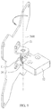
- FIG. 5 is a perspective view of a rotating module in accordance with another embodiment of the present invention.
- FIG. 6 is an exploded perspective view of the rotating module in accordance with the embodiment of the present invention.
- FIG. 7 is a perspective view of the arcuate arm in accordance with the embodiment of the present invention.
- FIG. 8 is a perspective view of the arcuate arms and the mandrel in accordance with the embodiment of the present invention.
- FIG. 9 is an operational view of the rotating module in accordance with the embodiment of the present invention.
- FIG. 10 is another perspective view of the arcuate arms and the mandrel in accordance with another embodiment of the present invention.
- FIG. 1 Please refer to the perspective view of the rotating module 1000 illustrated in FIG. 1 , wherein the rotating module 1000 is disposed on an upright 2000 , which is disposed on a working surface (not shown in figures), and connecting to a holder 3000 for supporting a display 4000 .
- FIG. 2 Please also refer to the exploded perspective view of the rotating module 1000 illustrated in FIG. 2 showing the rotating module 1000 mainly comprises a rubbing element 1 and a mandrel 2 .
- the rubbing element 1 includes an arcuate arm 11 and a connecting portion 12 , which are integrally formed.
- the arcuate arm 11 forms and defines a pivoting space 111 .
- the arcuate arm 11 also has an opening 112 and an inner surface 113 adjacent to the pivoting space 111 .
- the rotating module 1000 connects to the upright 2000 via the connecting portion 12 .
- the mandrel 2 includes a first fixing part 21 , a large-diameter part 22 , a pivoting part 23 , and a second fixing part 24 , sequentially.
- the pivoting part 23 passes through the arcuate arm 11 , contacts with the inner surface 113 , and has interference fit with the arcuate arm 11 .
- the first fixing part 21 and the second fixing part 24 extend from the pivoting part 23 and reach out of the arcuate arm 11 .
- the first fixing part 21 has two screw holes 211
- the second fixing part 24 has two screw holes 241 . Please refer to the bottom view of the rotating module 1000 .
- the large-diameter part 22 is formed between the pivoting part 23 and the first fixing part 21 , wherein the diameter D 1 of the cross-section of the large-diameter part 22 must be larger than the diameter D 2 of the cross-section of the pivoting part 23 . Accordingly, when the arcuate arm 11 is sleeved on the pivoting part 23 , the arcuate arm 11 abuts against the large-diameter part 22 so that the arcuate arm 11 may be accurately positioned during the assembling process.
- the diameter D 3 of the pivoting space 111 and the diameter D 2 of the cross-section of the pivoting part 23 are both constants, and the diameter D 3 of the pivoting space 111 is slightly smaller than the diameter D 2 of the cross-section of the pivoting part 23 .
- the arcuate arm 11 and the pivoting part 23 is capable of being tightly engaged to each other so that the pivoting part 23 and the arcuate arms 11 would have interference fit therebetween.
- the rubbing element 1 may still operatively rotate with respect to the mandrel 2 .
- the interference between the arcuate arm 11 and the pivoting part 23 decreases as the diameter D 3 of the pivoting space 111 increases, alternatively, as the diameter D 2 of the cross-section of the pivoting part 23 decreases.
- the large-diameter part 22 is integrally formed between the pivoting part 23 and the first fixing part 21 .
- the large-diameter part 22 may be a ring being fixed between the pivoting part 23 and the first fixing part 21 for the arcuate arm 11 abutting against.
- the extending direction of the mandrel 2 of the rotating module 1000 is perpendicular to the upright 2000 . Therefore, a tilt angle of the display 4000 may be changed by applying a force to the display 4000 or the holder 3000 . Also, the display 4000 may stop at any tilt angle with respect to the upright 2000 when the force is removed.
- the rubbing element 1 of the present embodiment is made by powder metallurgy with mixed powder of iron, palladium, and nickel.
- the material of the rubbing element 1 is not limited thereto and may be replaced by other materials.
- the location of the opening 112 of the arcuate arm 11 is not particularly limited.
- the location of the opening 112 may affect the intensity of the force applied for rotating the rotating module 1000 in different directions. Accordingly, the location of the opening 112 may be determined based on user's need. For instance, in the rotating module 1000 illustrated in FIG. 1 , the opening 112 of the arcuate arm 11 is formed adjacent to the connecting portion 12 and facing toward the working surface. When the tilt angle of the holder 3000 is adjusted to that as illustrated in FIG.
- the force applied to the holder 3000 should be more intense to resist the friction between the arcuate arm 11 and the pivoting part 23 ; on the contrary, the force applied to the holder 3000 may be less intense when the holder 3000 is inclined to the opposite direction.
- a plurality of rubbing elements 1 are sleeved on the pivoting part 23 of the mandrel 2 simultaneously, and connected to the upright 2000 via connecting portions 12 thereof respectively.
- the bearing weight of the holder 3000 may be adjusted by changing the number of the rubbing element 1 .
- the diameter D 2 of the cross-section of the pivoting part 23 decreases from one end to the other end, so that the pivoting part 23 is a frustum cone.
- the diameter D 3 of the pivoting space 111 also decreases from one end to the other end in order to correspond to the diameter D 2 of the cross-section of the pivoting part 23 so as to remain the interference fit between the pivoting part 23 and the arcuate arm 11 .
- the arcuate arm 11 and the connecting portion 12 are separated, and the number of the arcuate arm 11 may be plural.
- the rotating module 1000 mainly comprises a rubbing element 1 and a mandrel 2 , wherein the rubbing element 1 includes nine arcuate arms 11 , and a connecting portion 12 .
- the connecting portion 12 connects to the upright 2000 .
- Each of the arcuate arms 11 of the present embodiment has the same shape and size, and one of the arcuate arms 11 is illustrated in FIG. 7 .
- the arcuate arm 11 comprises a pivoting space 111 , an opening 112 and an inner surface 113 .
- the arcuate arms 111 are sequentially stacked and sleeved on the mandrel 2 , and the inner surfaces 113 of the arcuate arms 11 contact with the mandrel 2 .
- the mandrel 2 rotatably passes through the pivoting spaces 111 and includes a first fixing part 21 , a large-diameter part 22 , a pivoting part 23 , and a second fixing part 24 , wherein the large-diameter part 22 and the pivoting part 23 are connected to each other.
- the large-diameter part 22 has two first recesses 221 distant from the pivoting part 23 for assembling with the first fixing part 21
- the pivoting part 23 has two second recesses 231 distant from the large-diameter part 22 for assembling the second fixing part 24 .
- the arcuate arm 11 located at the most top position abuts against the large-diameter part 22 for preventing the displacement of the arcuate arms 11 .
- the diameter of each of the pivoting spaces 111 of the arcuate arms 11 is slightly smaller than the diameter of the pivoting part 23 of the mandrel 2 . Accordingly, the interference between the arcuate arms 11 and the mandrel 2 may occur; hence, the arcuate arms 11 are capable of being tightly sleeved on the mandrel 2 so that the mandrel 2 and the arcuate arms 11 are assembled with interference fit. However, the arcuate arms 11 may still pivotally rotate with respect to the mandrel 2 .
- the first fixing part 21 includes a first plate 212 and a second plate 213 , which are perpendicular to each other.
- the second fixing part 24 also includes a first plate 242 and a second plate 243 , which are perpendicular to each other.
- the first plate 212 of the first fixing part 21 has a first opening 2121 , wherein the first opening 2121 is assembled with one end of the large-diameter part 22 of the mandrel 2 .
- the first opening 2121 has a contour that essentially fits to the end of the large-diameter part 22 .
- the first opening 2121 engages with the two first recesses 221 , and the first fixing part 21 may further be fixed to the large-diameter part 22 by using a screw (not shown in figures).
- the first plate 242 of the second fixing part 24 has a second opening 2421 , wherein the second opening 2421 is assembled with one end of the pivoting part 23 .
- the second opening 2421 has a contour that essentially fits to the second recesses 231 , and the second fixing part 24 may further be fixed to the pivoting part 23 by using a screw (not shown in figures).
- the first fixing part 21 and the second fixing part 24 are engaged with the large-diameter part 22 and the pivoting part 23 respectively so that the large-diameter part 22 and the pivoting part 23 can be fixed and will not rotate with respect to the first fixing part 21 and the second fixing part 24 . Furthermore, the holder 3000 is fixed to the second plates 213 , 243 of the first fixing part 21 and the second fixing part 24 , and the holder 3000 is applied for carrying a display (not shown in figures).
- the connecting portion 12 includes a slot 121 and a stopper 122 , wherein the slot 121 has a cross-section that corresponds to the external contour of a portion of the arcuate arms 11 . More specifically, the cross-section of the slot 121 has a dovetail shape to accommodate the portion of the arcuate arms 11 .
- the arcuate arms 11 may be tightly engaged to the slot 121 so that each of the arcuate arms 11 being stackably sleeved on the pivoting part 23 may be fixed to the connecting portion 12 .
- the stopper 122 is fastened to the bottom of the slot 121 to enclose the opening beneath the slot 121 . Hence, the arcuate arms 11 will not be detached from the slot 121 due to gravity.
- the abovementioned embodiment is designed without using any springs; therefore, the assembling process would be simplified.
- the bearing force may be altered by adjusting the number of the arcuate arms 11 being stackably sleeved on the pivoting part 23 . Also, since the arcuate arms 11 are made with same size and shape, it would reduce the complexity of the manufacturing processes.
- the arcuate arms 11 with different standards may be used to adjust the total interference between the arcuate arms 11 and the pivoting part 23 .
- the interference between the arcuate arm 11 and the pivoting part 23 may decrease while the diameter of the pivoting space 111 increases. Therefore, the adjustment may be accomplished by using the arcuate arms 11 with different standards.
- FIG. 10 illustrates that some of the arcuate arms 11 ′ have different thickness. As illustrated in the figure, the combinations of different arcuate arms 11 , 11 ′ is able to adjust the interference to balance the weight of the display.
- the disposing direction and position of the rubbing element 1 and the mandrel 2 may be designed as needed in order to adjust the display 4000 with the tilt angle, the portrait/landscape rotate angle, or the swivel angle along the upright 2000 .
- a force may be applied to the display 4000 to change the swivel angle of the display 4000 , and when the force is removed, the display 4000 may stop at any desired swivel angles with respect to the upright 2000 .
- a force may be applied to the display 4000 to change the tilt angle of the display 4000 , and when the force is removed, the display 4000 may stop at any desired tilt angles with respect to the upright 2000 .
- the friction provided by the rotating module of the present invention may be altered by adjusting the number or the thickness of the arcuate arms of the rubbing element, to adjust the interference level between the arcuate arms and the pivoting part. Accordingly, the rotating module may be applied with displays with different weights; therefore, it is not necessary to customize the rotating module for displays with different weight.
Landscapes
- Engineering & Computer Science (AREA)
- General Engineering & Computer Science (AREA)
- Mechanical Engineering (AREA)
- Devices For Indicating Variable Information By Combining Individual Elements (AREA)
- Pivots And Pivotal Connections (AREA)
Abstract
Description
Claims (18)
Applications Claiming Priority (6)
| Application Number | Priority Date | Filing Date | Title |
|---|---|---|---|
| TW106217398U TWM560155U (en) | 2017-11-23 | 2017-11-23 | Swivel module |
| TW106217398 | 2017-11-23 | ||
| TW106217398U | 2017-11-23 | ||
| TW107203874 | 2018-03-26 | ||
| TW107203874U | 2018-03-26 | ||
| TW107203874U TWM564676U (en) | 2018-03-26 | 2018-03-26 | Swivel module |
Publications (2)
| Publication Number | Publication Date |
|---|---|
| US20190154192A1 US20190154192A1 (en) | 2019-05-23 |
| US10794530B2 true US10794530B2 (en) | 2020-10-06 |
Family
ID=66532799
Family Applications (1)
| Application Number | Title | Priority Date | Filing Date |
|---|---|---|---|
| US16/191,832 Active US10794530B2 (en) | 2017-11-23 | 2018-11-15 | Rotating module |
Country Status (1)
| Country | Link |
|---|---|
| US (1) | US10794530B2 (en) |
Cited By (1)
| Publication number | Priority date | Publication date | Assignee | Title |
|---|---|---|---|---|
| US20220252208A1 (en) * | 2021-02-08 | 2022-08-11 | Syncmold Enterprise Corp. | Display supporting device |
Families Citing this family (3)
| Publication number | Priority date | Publication date | Assignee | Title |
|---|---|---|---|---|
| USD916944S1 (en) * | 2018-05-04 | 2021-04-20 | ATA Industries, Inc. | Smart device holder |
| KR102425868B1 (en) * | 2020-10-12 | 2022-07-27 | 엘지전자 주식회사 | Display device |
| CN113958818B (en) * | 2021-11-04 | 2023-01-10 | 湖南科灏电子科技有限责任公司 | A liquid crystal display support for easy angle adjustment |
Citations (4)
| Publication number | Priority date | Publication date | Assignee | Title |
|---|---|---|---|---|
| US6554238B1 (en) * | 1999-11-18 | 2003-04-29 | Claiteal Pty. Limited | Support arm for visual display unit |
| US6863252B2 (en) * | 2000-03-30 | 2005-03-08 | Peter Thomas Bosson | Display device support system |
| US20060261228A1 (en) * | 2005-05-20 | 2006-11-23 | Chin-Jui Hung | Monitor-holding device |
| US9316346B2 (en) * | 2010-06-09 | 2016-04-19 | Colebrook Bosson Saunders (Products) Limited | Support system |
-
2018
- 2018-11-15 US US16/191,832 patent/US10794530B2/en active Active
Patent Citations (4)
| Publication number | Priority date | Publication date | Assignee | Title |
|---|---|---|---|---|
| US6554238B1 (en) * | 1999-11-18 | 2003-04-29 | Claiteal Pty. Limited | Support arm for visual display unit |
| US6863252B2 (en) * | 2000-03-30 | 2005-03-08 | Peter Thomas Bosson | Display device support system |
| US20060261228A1 (en) * | 2005-05-20 | 2006-11-23 | Chin-Jui Hung | Monitor-holding device |
| US9316346B2 (en) * | 2010-06-09 | 2016-04-19 | Colebrook Bosson Saunders (Products) Limited | Support system |
Cited By (2)
| Publication number | Priority date | Publication date | Assignee | Title |
|---|---|---|---|---|
| US20220252208A1 (en) * | 2021-02-08 | 2022-08-11 | Syncmold Enterprise Corp. | Display supporting device |
| US11629811B2 (en) * | 2021-02-08 | 2023-04-18 | Syncmold Enterprise Corp. | Display supporting device |
Also Published As
| Publication number | Publication date |
|---|---|
| US20190154192A1 (en) | 2019-05-23 |
Similar Documents
| Publication | Publication Date | Title |
|---|---|---|
| US10794530B2 (en) | Rotating module | |
| CA2028068C (en) | Adjustable damping and load balancing system for a camera panhead | |
| US8405959B2 (en) | Vertical positioning unit for display device and display device having the same | |
| CN216079023U (en) | Supporting device | |
| US20190353295A1 (en) | Display stand | |
| US20070194183A1 (en) | Stand of display device | |
| CN101858482B (en) | Supporting mechanism | |
| US9062811B2 (en) | Support structure and electronic device using same | |
| US8196875B2 (en) | Support stand with intermediate connecting assembly | |
| CN211925263U (en) | Adjustable supporting seat | |
| US11629811B2 (en) | Display supporting device | |
| US20050029424A1 (en) | Adjusting assembly for LCD monitor | |
| US11317527B2 (en) | Supporting device | |
| US9188272B2 (en) | Display device with variable height and angles of view by virtue of rotatable stand | |
| WO2013023277A1 (en) | Mounting device for camera | |
| JP2015530789A (en) | Tilt mechanism for monitor | |
| TW202300812A (en) | Display stand holder with sliding rail structure and display apparatus thereof | |
| CN114658997B (en) | Display support | |
| CN101498336B (en) | Hinge and display device having the same | |
| JP4173737B2 (en) | Counter balance mechanism and pan / tilt head | |
| US11122702B1 (en) | Monitor support device and a display apparatus having the same | |
| CN207961973U (en) | pivot module | |
| CN203010153U (en) | An adjustable support structure for flat panel TV | |
| TW201730474A (en) | Holder | |
| CN208107516U (en) | Pin joint module |
Legal Events
| Date | Code | Title | Description |
|---|---|---|---|
| FEPP | Fee payment procedure |
Free format text: ENTITY STATUS SET TO UNDISCOUNTED (ORIGINAL EVENT CODE: BIG.); ENTITY STATUS OF PATENT OWNER: LARGE ENTITY |
|
| AS | Assignment |
Owner name: SYNCMOLD ENTERPRISE CORP., TAIWAN Free format text: ASSIGNMENT OF ASSIGNORS INTEREST;ASSIGNORS:YEH, CHIEN-CHENG;YEN, CHING-HUI;LI, ZE-WEI;REEL/FRAME:047804/0918 Effective date: 20180925 |
|
| STPP | Information on status: patent application and granting procedure in general |
Free format text: APPLICATION DISPATCHED FROM PREEXAM, NOT YET DOCKETED |
|
| STPP | Information on status: patent application and granting procedure in general |
Free format text: DOCKETED NEW CASE - READY FOR EXAMINATION |
|
| STPP | Information on status: patent application and granting procedure in general |
Free format text: NON FINAL ACTION MAILED |
|
| STPP | Information on status: patent application and granting procedure in general |
Free format text: NON FINAL ACTION MAILED |
|
| STPP | Information on status: patent application and granting procedure in general |
Free format text: PUBLICATIONS -- ISSUE FEE PAYMENT VERIFIED |
|
| STCF | Information on status: patent grant |
Free format text: PATENTED CASE |
|
| MAFP | Maintenance fee payment |
Free format text: PAYMENT OF MAINTENANCE FEE, 4TH YEAR, LARGE ENTITY (ORIGINAL EVENT CODE: M1551); ENTITY STATUS OF PATENT OWNER: LARGE ENTITY Year of fee payment: 4 |