US10793041B2 - Method for producing an adjusting device for a vehicle seat, and adjusting device - Google Patents
Method for producing an adjusting device for a vehicle seat, and adjusting device Download PDFInfo
- Publication number
- US10793041B2 US10793041B2 US16/308,043 US201716308043A US10793041B2 US 10793041 B2 US10793041 B2 US 10793041B2 US 201716308043 A US201716308043 A US 201716308043A US 10793041 B2 US10793041 B2 US 10793041B2
- Authority
- US
- United States
- Prior art keywords
- hollow body
- pressure medium
- film
- connecting portion
- adjusting device
- Prior art date
- Legal status (The legal status is an assumption and is not a legal conclusion. Google has not performed a legal analysis and makes no representation as to the accuracy of the status listed.)
- Active, expires
Links
Images


Classifications
-
- B—PERFORMING OPERATIONS; TRANSPORTING
- B60—VEHICLES IN GENERAL
- B60N—SEATS SPECIALLY ADAPTED FOR VEHICLES; VEHICLE PASSENGER ACCOMMODATION NOT OTHERWISE PROVIDED FOR
- B60N2/00—Seats specially adapted for vehicles; Arrangement or mounting of seats in vehicles
- B60N2/90—Details or parts not otherwise provided for
- B60N2/914—Hydro-pneumatic adjustments of the shape
-
- B—PERFORMING OPERATIONS; TRANSPORTING
- B29—WORKING OF PLASTICS; WORKING OF SUBSTANCES IN A PLASTIC STATE IN GENERAL
- B29L—INDEXING SCHEME ASSOCIATED WITH SUBCLASS B29C, RELATING TO PARTICULAR ARTICLES
- B29L2031/00—Other particular articles
- B29L2031/771—Seats
-
- B—PERFORMING OPERATIONS; TRANSPORTING
- B60—VEHICLES IN GENERAL
- B60N—SEATS SPECIALLY ADAPTED FOR VEHICLES; VEHICLE PASSENGER ACCOMMODATION NOT OTHERWISE PROVIDED FOR
- B60N2/00—Seats specially adapted for vehicles; Arrangement or mounting of seats in vehicles
- B60N2/90—Details or parts not otherwise provided for
- B60N2/976—Details or parts not otherwise provided for massaging systems
Definitions
- the present invention concerns a method for producing an adjusting device for a vehicle seat, in particular a pneumatic adjusting device for changing a contour of a seat bearing surface of the vehicle seat. Furthermore, the present invention concerns an adjustment device itself, in particular in the form of a pneumatic device for changing a contour of a seat bearing surface of a vehicle seat. The present invention also relates to a vehicle seat having an adjusting device of said type.
- bladders which can be filled with a pressure medium, in particular with a gaseous pressure medium such as compressed air, are situated as actuating elements in the region of the seat surface or backrest (together also referred to as the seat bearing surface), and can be supplied with pressure medium via a respective pressure medium line.
- a respective bladder By filling a respective bladder with pressure medium, its volume is increased so that the properties of a seat backrest or surface in relation to the contour can be changed.
- the pressure medium is firstly generated by a pressure medium source, for example by a compressor or a compressor unit, and guided via a corresponding valve, in particular an electropneumatic valve of a control unit, to a respective bladder.
- an arrangement described above may be produced from one or more bladders with respective assigned pressure medium lines. It is here conceivable that the respective bladders are produced from two or more flexible films, wherein the films are welded together at a connecting seam to form a respective bladder. If a bladder with for example three chambers is to be produced, two films must be welded accordingly three times in order to form three bladder chambers or pressure medium chambers, which then in a further method step are joined together to form a single bladder with three chambers. With a pneumatic adjusting device with a plurality of such three-chamber bladders in particular, the manufacturing process for producing such an adjusting device is very complex.
- An aspect of the present invention aims to create a possibility of minimizing the manufacturing complexity for producing an adjusting device.
- a method for producing an adjusting device in particular for a vehicle seat, is made available.
- This may be a pneumatic device for changing a contour of a seat bearing surface of the vehicle seat.
- a flexible hollow body is molded from a thermoplastic plastic, wherein the hollow body forms a pressure medium chamber and has an opening which is surrounded by a connecting portion.
- a first film in particular a flexible plastic film, is arranged at the opening.
- the first film is connected to the hollow body at the connecting portion of the opening at a connecting seam in order to thereby close off the pressure medium chamber. Because the hollow body is now formed in one step, the manufacturing complexity can be reduced in comparison with production of a bladder from several film portions.
- the hollow body is produced by an injection molding process of the thermoplastic plastic.
- a hollow body even with complex design, can be produced in a single method step and in a simple economic process, so that the manufacturing complexity is thereby further minimized.
- a one-piece (three-dimensional), flexible hollow body is created with great design freedom.
- the flexible hollow body may be produced by a deep-drawing process from a second film, in particular a flexible plastic film (of a thermoplastic plastic).
- a second film in particular a flexible plastic film (of a thermoplastic plastic).
- the hollow body may be molded by a simple method in a single process step, so that the manufacturing complexity can be minimized.
- a one-piece (three-dimensional), flexible hollow body is created from the second film with great design freedom.
- the opening and the connecting portion surrounding this lie in one plane, so that a flat connecting seam is produced on connection to the first film. Firstly, a flat connecting seam is thus produced in a simple process and guarantees great stability.
- the hollow body itself, this may assume various shapes or geometries such as for example radii, surface structures and receivers.
- the hollow body has one or more chambers which may be filled with pressure medium and, in the case of several chambers, are connected together by a pressure medium channel. The greater the number of chambers, the greater the lift which the hollow body can exert when filled with pressure medium.
- the hollow body has the shape of a bellows with one or more folds. In particular, the hollow body has two or more folds in order thus to generate a sufficiently great lift and hence produce a contour change of the seat bearing surface which is perceptible to an occupant or user of the vehicle seat.
- the hollow body By forming the hollow body with one or more folds which are then opened or unfolded on filling with pressure medium and collapsed again on evacuation of the hollow body, a controlled lift of the hollow body can be ensured. Furthermore, the formation of folds in the hollow body improves the mechanical stability on raising and lowering (or filling and evacuating). Finally, it must be stated that in particular with an integrally formed injection-molded or deep-drawn hollow body, in particular with worked-in folds, due to the one-piece design the robustness and hence the quality is improved (due to the absence of weld seams between films for forming pressure medium chambers).
- a pressure medium line in particular in the form of a hose made of a plastic or rubber, for introducing pressure medium into the pressure medium chamber is inserted between the connecting portion and the first film.
- the pressure medium line may here be provided for the introduction of pressure medium and/or for the evacuation of pressure medium.
- the hollow body may then be connected to the first film and additionally to the pressure medium line or lines via a connecting seam, so that a sealed pressure medium chamber is created in the hollow body which can only exchange pressure medium with the environment via the one or more pressure medium lines.
- the first film (in particular on a side opposite the hollow body) is connected to a carrier film for holding the hollow body at a second connecting seam. It is here conceivable that not only the hollow body but also further hollow bodies are connected to the carrier film at further second connecting seams, in order thus to create an adjusting device with several hollow bodies as actuating elements which are held by the carrier film and hence can easily be installed in the vehicle seat.
- this consists of a first and a second film layer which are arranged adjacent to each other, wherein by connecting the first and second film layers along a line-side connecting seam, a second pressure medium line is formed to create a pressure medium connection to the carrier film.
- This second pressure medium line may then also serve as a pressure medium connection to the pressure medium chamber of the hollow body.
- the carrier film consists of a first and a second film layer which may form a second pressure medium line by connection along a line-side connecting seam
- this carrier film structure it is also conceivable to develop this carrier film structure further. Consequently, it is conceivable, in the step of molding the flexible hollow body, to form the second film layer from a thermoplastic plastic with one or more flexible hollow bodies which are held together by portions of the second film layer.
- the first film layer of the carrier film may be used as the first film, which is connected to the second film layer so as to close off the respective hollow bodies at one or more line-side connecting seams between the two film layers and form one or more pressure medium lines, in order to supply the hollow body or bodies in the second film layer with pressure medium (or evacuate pressure medium therefrom).
- the film layers of the carrier film may not only perform the function of holding together actuating devices which can be filled with pressure medium, but in addition constitute pressure medium lines and also the actuating elements in the form of hollow bodies in the second film layer of the carrier film.
- actuating devices which can be filled with pressure medium
- the film layers of the carrier film may not only perform the function of holding together actuating devices which can be filled with pressure medium, but in addition constitute pressure medium lines and also the actuating elements in the form of hollow bodies in the second film layer of the carrier film.
- an adjusting device is created with minimum complexity in terms of manufacturing and tooling.
- the carrier film consists of a first and a second film layer which are arranged adjacent to each other, wherein the first film layer forms the first film described above, and the second film layer has the flexible hollow body, and wherein by connecting the first film layer to the second film layer along a line-side connecting seam, a (or a further) pressure medium line is formed in order to create a pressure medium connection to the pressure medium chamber of the flexible hollow body.
- the step of molding furthermore comprises molding of at least one further flexible hollow body from a thermoplastic plastic with an opening which is surrounded by a connecting portion, wherein between the hollow body and the at least one further hollow body, a connecting web is formed or molded which holds the hollow bodies together.
- the connecting webs already hold the hollow bodies together so they do not have to be mounted on a separate carrier film (for example welded) to guarantee being held together for mounting.
- the hollow bodies may then be closed off again by corresponding first films.
- first, second and line-side connecting seams are weld seams, or these connecting seams are produced by welding, in particular high-frequency welding. This constitutes a favourable joining method which gives the adjusting device great robustness.
- At least one lift-limiting element may be formed or molded which prevents an expansion of the hollow body beyond a predefined extent during filling.
- the at least one lift-limiting element may be molded on the outside of the hollow body.
- the at least one lift-limiting element may be a strap-like structure with a specific length which, in particular in a hollow body with a fold (bellows) structure, is attached between the folds. When the hollow body expands and hence when the folds move apart, the strap-like structure is thus stretched to the specific length and then stops the folds from moving further apart.
- Another aspect of the present invention provides an adjusting device in particular for a vehicle seat.
- This may be a pneumatic device for changing a contour of a seat bearing surface of the vehicle seat.
- This adjusting device has a flexible hollow body molded from a thermoplastic plastic, which forms a pressure medium chamber and has an opening which is surrounded by a connecting portion. Furthermore, it has a first film which is connected to the hollow body at the connecting portion of the opening at a connecting seam in order to thereby close off the pressure medium chamber.
- the flexible hollow body is produced by an injection molding process of the thermoplastic plastic.
- the hollow body for forming the pressure medium chambers is produced using simple processes with little manufacturing complexity, and may have almost any arbitrarily complex design with one or more pressure medium (part) chambers or for example have the form of a bellows.
- a pressure medium line for the introduction (and where applicable evacuation) of pressure medium into the pressure medium chamber is inserted at the connecting seam between the first film and the connecting portion of the hollow body. It is also conceivable that several pressure medium lines may be inserted which may then be connected by the connecting seam to the other components, the hollow body and the first film, in order to create a sealed pressure medium chamber in the hollow body which can only exchange pressure medium via the pressure medium line(s).
- a vehicle seat which has a seat bearing surface for a user.
- the vehicle seat comprises an adjusting device according to one of the embodiments described above, which is arranged in the vehicle seat so as to change the contour of the seat bearing surface.
- Advantageous configurations of the method may, insofar as applicable to the adjusting device and the vehicle seat, also be regarded as advantageous configurations of the adjusting device and the vehicle seat, and vice versa.
- FIGS. 1A-1E a diagrammatic depiction of a method for producing an adjusting device for a vehicle seat according to a first embodiment of the invention
- FIG. 2 a diagrammatic depiction of an adjusting device according to a second embodiment of the invention
- FIG. 3 a diagrammatic depiction of an adjusting device for a vehicle seat according to a third embodiment
- FIG. 4 a hollow body for an adjusting device for a vehicle seat according to one embodiment of the invention with a lift-limiting device
- FIG. 5 a diagrammatic depiction of a vehicle seat according to one embodiment of the invention, in which a carrier film with a plurality of hollow bodies, as actuating elements for influencing the contour of the seat bearing surface of the vehicle seat, is arranged in the seat bearing surface in the region of the backrest.
- FIGS. 1A-1E shows diagrammatically the sequence of a method for producing an adjusting device for a vehicle seat, in particular a pneumatic adjusting device for changing a contour of a seat bearing surface of the vehicle seat.
- a tool WZ is provided which in the diagrammatic depiction here consists of two tool parts WT 1 and WT 2 .
- the tool parts WT 1 and WT 2 are arranged or oriented relative to each other such that a gap SP is created between them.
- This gap is dimensioned and designed such that it corresponds to a hollow body which can be produced in an injection molding process using the tool WZ.
- FIG. 1A-1E shows diagrammatically the sequence of a method for producing an adjusting device for a vehicle seat, in particular a pneumatic adjusting device for changing a contour of a seat bearing surface of the vehicle seat.
- TPU thermoplastic polyurethane
- thermoplastic plastic When the thermoplastic plastic is then in the solid state (as an injection-molding), in a second step it can be removed as a finished component by opening the tool, giving a hollow body HK as shown in FIG. 1B .
- This hollow body of flexible form substantially has the shape of a bellows closed at one end (the upper end) with three outwardly directed folds FA 1 , FA 2 , FA 3 .
- Three part chambers TK 1 , TK 2 and TK 3 are formed in the region of the three folds and together form a pressure medium chamber DK.
- FIG. 1B shows, at the lower end the hollow body HK has an opening OF which is surrounded by a connecting portion VA.
- a pressure medium line DML is arranged at the opening OF of the hollow body such that an end portion EA of the pressure medium line DML is situated in the region of the opening OF.
- a first flexible film F 1 is also arranged in the region of the connecting portion VA, so that the pressure medium line DML is situated between the first film and the connecting portion.
- the connecting portion VA of the hollow body is now connected to the first film F 1 and to the pressure medium line DML along a connecting seam VBN 1 .
- the connecting portion VA terminates in a plane E so that the film F 1 can be connected easily and precisely to the connecting portion VA along the connecting seam VBN 1 .
- This connection preferably takes place via a welding process, in particular a high-frequency welding process.
- FIG. 1D it has been shown how a single actuating element SE can be produced in the form of the hollow body HK with the pressure medium chamber DK which can be filled with pressure medium.
- this actuating element SE it may be advantageous to apply this to a carrier film.
- This is carried out in a fifth step as shown in FIG. 1E .
- the actuating element SE of FIG. 1D is applied to a carrier film TF via a second connecting seam VBN 2 .
- This connection by means of the second connecting seam VBN 2 may again be a welding process, e.g. a high-frequency welding process.
- the carrier film may then comprise special contours or holders etc. which allow simple installation on the vehicle seat.
- an actuating element SE installed in the vehicle seat as part of an adjusting device for changing the contour of the seat bearing surface for a vehicle seat, but two or more actuating elements SE may also be installed. It is therefore conceivable that several actuating elements SE, produced as shown up to step 4 in FIG. 1D , may be applied to the carrier film TF and connected by a respective second connecting seam VBN 2 . In this way, an adjusting device can be achieved with a wide range of actuating possibilities for changing the contour of the seat bearing surface of the vehicle seat.
- FIG. 2 shows a second embodiment of an adjusting device VV 2 .
- the production steps used are similar to those shown in FIGS. 1A-1D .
- the difference for the second embodiment of the adjusting device VV 2 is that to produce the hollow bodies HK 1 , HK 2 and HK 3 , use is not made of separate tools as shown in FIGS.
- both pressure medium lines DML 1 , DML 2 and DML 3 , and first films F 11 , F 12 , F 13 are arranged at the respective openings OF 1 , OF 2 , OF 3 or the connecting portions VA 1 , VA 2 and VA 3 surrounding these, as shown in step 3 in FIG. 1C , wherein these elements are then joined together by respective connecting seams VBN 11 , VBN 12 and VBN 13 , as shown in the fourth step in FIG. 1D (in particular by welding or high-frequency welding).
- the advantage of the adjusting device according to FIG. 2 is now that the individual hollow bodies HK 1 , HK 2 and HK 3 or the resulting actuating elements SE 1 , SE 2 and SE 3 are joined together by the respective webs ST 12 , ST 23 etc., in order then to be installed as the actuating device VV 2 on a vehicle seat. Forming the webs between the hollow bodies or actuating elements then means that no additional carrier film TF is required, so the complexity of tooling and manufacturing can be reduced.
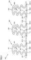
- FIG. 3 shows an adjusting device VV 3 according to a third embodiment of the invention.
- a carrier film TF 3 is used, wherein the individual film layers of the carrier film perform several functions.
- the carrier film TF 3 comprises two film layers L 11 and L 22 which have a connecting seam VBN 4 at various points or lines, in order thereby to form pressure medium lines such as a pressure medium line DL 23 between the film layers L 11 and L 22 .
- This formation of pressure medium lines between the film layers thus constitutes a further function of the film layer or carrier film.
- a further function or property of the carrier film TF 3 is that the second film layer L 22 has already been produced with a special structure or special profile. More precisely, the film layer L 22 has been produced by an injection molding process from a thermoplastic plastic material such as TPU. In other words, it is conceivable that the second film layer L 22 has been produced using an injection molding process, as shown in FIGS. 1A and 1B , so that the second film layer L 22 now comprises a hollow body HK 4 with a pressure medium chamber DK 4 (shown in FIG. 4 as pressure medium chambers DK 41 , DK 42 ) situated therein.
- a pressure medium chamber DK 4 shown in FIG. 4 as pressure medium chambers DK 41 , DK 42
- Pressure medium DM which flows through the pressure medium line DL 23 , can finally flow into the pressure medium chamber DK 4 through an opening OF 4 of the hollow body HK 4 .
- the pressure medium chamber DK 4 is filled with pressure medium and expands upward in the image plane along arrow AB and hence generates a lift in the direction of arrow AB.
- this lift creates a force which acts on the seat bearing surface in order to change its contour.
- the film L 11 may then be regarded as the first film in FIG. 1 , since this closes off the pressure medium chamber DK 4 and pressure medium can be exchanged with the environment only via the pressure medium line DL 23 .
- FIG. 4 shows a further embodiment of a hollow body HK 5 .
- This hollow body HK 5 (having pressure medium chamber DMK), which was produced following the steps in FIGS. 1A and 1B , is that this hollow body HK 5 comprises lift-limiting elements HB 1 -HB 4 on the outside. These lift-limiting elements are arranged between two folds and in particular in the vicinity of the (outwardly directed) fold tips.
- the lift-limiting element HB 1 is arranged between the folds FA 1 and FA 2 .
- This lift-limiting element HB 1 has a length LHB which is shorter than the length LHF of the hollow body depression HE.
- FIG. 5 shows a vehicle seat FZS.
- This vehicle seat comprises a seat cushion SPO and a backrest cushion RPO.
- a seat surface SF on the seat cushion SPO and a backrest RL on the backrest cushion RPO each form a portion of a seat bearing surface of the vehicle seat FZS.
- a carrier film TF 5 is applied to the part of the seat bearing surface formed by the backrest RL.
- the adjusting device constructed on the basis of the carrier film TF 5 substantially corresponds to the adjusting device VV 1 of FIG. 1E , with the difference that here, instead of one hollow body, five hollow bodies HK 11 , HK 12 , HK 13 , HK 14 and HK 15 are arranged on the carrier film to form respective actuating elements. It is however also conceivable to arrange more or fewer actuating elements on the carrier film TF 5 . It is furthermore conceivable that adjusting devices similar in structure to the adjusting devices VV 2 and VV 3 may be arranged on the vehicle seat.
- a cover STO composed for example of cloth or leather, may be provided over the hollow bodies HK 11 -HK 15 and form the contour K of the backrest RL, which can be influenced by the hollow bodies HK 11 -HK 15 .
- the hollow bodies HK 11 -HK 15 or the pressure medium chambers formed therein are again connected to corresponding pressure, medium lines D 1 -D 5 , which can finally be connected to an adapter element AL of a control unit STG.
- the control unit STG serves to provide pressure medium such as air, which is provided via a pressure medium source DQ, to the hollow bodies HK 11 -HK 15 selectively via the pressure medium lines D 1 -D 5 , in particular via electropneumatic valves, in particular for a massage function.
- pneumatic adjusting devices for a vehicle seat can be produced with little complexity in terms of manufacturing and tooling, and with high robustness.
Landscapes
- Engineering & Computer Science (AREA)
- Aviation & Aerospace Engineering (AREA)
- Transportation (AREA)
- Mechanical Engineering (AREA)
- Injection Moulding Of Plastics Or The Like (AREA)
Abstract
Description
Claims (12)
Applications Claiming Priority (4)
| Application Number | Priority Date | Filing Date | Title |
|---|---|---|---|
| DE102016212606.7A DE102016212606A1 (en) | 2016-07-11 | 2016-07-11 | Method for producing an adjusting device for a vehicle seat and adjusting device |
| DE102016212606 | 2016-07-11 | ||
| DE102016212606.7 | 2016-07-11 | ||
| PCT/EP2017/067351 WO2018011184A1 (en) | 2016-07-11 | 2017-07-11 | Method for producing an adjusting device for a vehicle seat, and adjusting device |
Publications (2)
| Publication Number | Publication Date |
|---|---|
| US20190255977A1 US20190255977A1 (en) | 2019-08-22 |
| US10793041B2 true US10793041B2 (en) | 2020-10-06 |
Family
ID=59313257
Family Applications (1)
| Application Number | Title | Priority Date | Filing Date |
|---|---|---|---|
| US16/308,043 Active 2037-08-01 US10793041B2 (en) | 2016-07-11 | 2017-07-11 | Method for producing an adjusting device for a vehicle seat, and adjusting device |
Country Status (3)
| Country | Link |
|---|---|
| US (1) | US10793041B2 (en) |
| DE (1) | DE102016212606A1 (en) |
| WO (1) | WO2018011184A1 (en) |
Cited By (4)
| Publication number | Priority date | Publication date | Assignee | Title |
|---|---|---|---|---|
| US20220072985A1 (en) * | 2020-09-08 | 2022-03-10 | Grammer Ag | Vehicle seat having a fluid chamber unit |
| US12326742B2 (en) | 2022-12-22 | 2025-06-10 | Lear Corporation | Valve and actuator assembly for a fluid system in a vehicle seat assembly |
| US12337738B2 (en) | 2022-11-09 | 2025-06-24 | Lear Corporation | Fluid system for a vehicle seat assembly |
| US12358411B2 (en) | 2022-04-01 | 2025-07-15 | Lear Corporation | Vehicle seat subassemblies |
Families Citing this family (2)
| Publication number | Priority date | Publication date | Assignee | Title |
|---|---|---|---|---|
| CN109732858B (en) * | 2018-12-24 | 2020-02-18 | 西安交通大学 | A small dense multi-point flexible mold |
| DE102023120958A1 (en) * | 2023-08-07 | 2025-02-13 | Faurecia Autositze Gmbh | module carrier arrangement |
Citations (19)
| Publication number | Priority date | Publication date | Assignee | Title |
|---|---|---|---|---|
| US5558398A (en) * | 1993-11-08 | 1996-09-24 | Santos; James P. | Self-adjusting seating system |
| US6212719B1 (en) * | 1997-10-10 | 2001-04-10 | D2Rm Corp. | Air massager cushioning device |
| US6551450B1 (en) * | 1997-10-10 | 2003-04-22 | D2Rm Corp. | Unique air and sonic massaging apparatus |
| WO2004026623A1 (en) | 2002-09-14 | 2004-04-01 | Daimlerchrysler Ag | Vehicle seat having a massage function and contour adjustment |
| US6916300B2 (en) * | 2002-11-14 | 2005-07-12 | Bowles Fluidics Corporation | Seat massager |
| US20060085919A1 (en) * | 2004-08-16 | 2006-04-27 | Kramer Kenneth L | Dynamic cellular person support surface |
| US20060217644A1 (en) * | 2005-01-19 | 2006-09-28 | Takashi Ozaki | Vehicle seats |
| US20080080793A1 (en) | 2006-09-29 | 2008-04-03 | Toyota Boshoku Kabushiki Kaisha | Gas bags for massaging device |
| DE102007051759A1 (en) | 2007-10-30 | 2009-05-07 | Bayerische Motoren Werke Aktiengesellschaft | Seat e.g. front seat, for vehicle i.e. motor vehicle such as passenger car, has blisters directly impacting on foam part at side facing seat user to produce laminar pressure and laminar contour change that exceed blisters size |
| US20100031449A1 (en) * | 2007-01-17 | 2010-02-11 | Chienchuan Cheng | Mattress adjusting system |
| US20110203589A1 (en) * | 2010-02-23 | 2011-08-25 | Uam Global Llc | Ventilating element, system, and methods |
| US8162398B2 (en) * | 2009-03-26 | 2012-04-24 | Schukra of North America Co. | Zone lumbar massage system |
| DE102012201417A1 (en) | 2012-02-01 | 2013-04-18 | Alfmeier Präzision AG Baugruppen und Systemlösungen | Method for manufacturing pneumatic deformable blister element for formation of motor car seat, involves forming depression in blister walls by thermoplastic deformation, and hermitically sealing depression of each wall with other wall |
| DE102013003674A1 (en) | 2013-03-02 | 2014-09-04 | Sitech Sitztechnik Gmbh | Vehicle seat for motor car, has seatback and cushion provided with multiple massage elements, which are arranged on view side of covering and hose-like connection that is arranged between massage elements |
| US20150025425A1 (en) * | 2011-11-15 | 2015-01-22 | Barrett Reed Mitchell | Medical Vest for High Frequency Chest Wall Oscillation (HFCWO) System |
| DE102014219343A1 (en) | 2014-09-24 | 2015-09-10 | Conti Temic Microelectronic Gmbh | Pneumatic adjustment arrangement |
| US9725177B2 (en) * | 2015-10-20 | 2017-08-08 | Ami Industries, Inc. | Pneumatic comfort seats |
| US9802518B2 (en) * | 2012-03-06 | 2017-10-31 | Conti Temic Microelectronic Gmbh | Pneumatic adjustment arrangement for a vehicle seat |
| US10406063B2 (en) * | 2013-05-15 | 2019-09-10 | Respinnovation | Medical equipment for high frequency chest wall oscillation (HFCWO) treatment |
-
2016
- 2016-07-11 DE DE102016212606.7A patent/DE102016212606A1/en not_active Ceased
-
2017
- 2017-07-11 WO PCT/EP2017/067351 patent/WO2018011184A1/en not_active Ceased
- 2017-07-11 US US16/308,043 patent/US10793041B2/en active Active
Patent Citations (20)
| Publication number | Priority date | Publication date | Assignee | Title |
|---|---|---|---|---|
| US5558398A (en) * | 1993-11-08 | 1996-09-24 | Santos; James P. | Self-adjusting seating system |
| US6212719B1 (en) * | 1997-10-10 | 2001-04-10 | D2Rm Corp. | Air massager cushioning device |
| US6551450B1 (en) * | 1997-10-10 | 2003-04-22 | D2Rm Corp. | Unique air and sonic massaging apparatus |
| WO2004026623A1 (en) | 2002-09-14 | 2004-04-01 | Daimlerchrysler Ag | Vehicle seat having a massage function and contour adjustment |
| US20060049678A1 (en) | 2002-09-14 | 2006-03-09 | Daimlerchrysler Ag | Vehicle seat having a massage function and contour adjustment |
| US6916300B2 (en) * | 2002-11-14 | 2005-07-12 | Bowles Fluidics Corporation | Seat massager |
| US20060085919A1 (en) * | 2004-08-16 | 2006-04-27 | Kramer Kenneth L | Dynamic cellular person support surface |
| US20060217644A1 (en) * | 2005-01-19 | 2006-09-28 | Takashi Ozaki | Vehicle seats |
| US20080080793A1 (en) | 2006-09-29 | 2008-04-03 | Toyota Boshoku Kabushiki Kaisha | Gas bags for massaging device |
| US20100031449A1 (en) * | 2007-01-17 | 2010-02-11 | Chienchuan Cheng | Mattress adjusting system |
| DE102007051759A1 (en) | 2007-10-30 | 2009-05-07 | Bayerische Motoren Werke Aktiengesellschaft | Seat e.g. front seat, for vehicle i.e. motor vehicle such as passenger car, has blisters directly impacting on foam part at side facing seat user to produce laminar pressure and laminar contour change that exceed blisters size |
| US8162398B2 (en) * | 2009-03-26 | 2012-04-24 | Schukra of North America Co. | Zone lumbar massage system |
| US20110203589A1 (en) * | 2010-02-23 | 2011-08-25 | Uam Global Llc | Ventilating element, system, and methods |
| US20150025425A1 (en) * | 2011-11-15 | 2015-01-22 | Barrett Reed Mitchell | Medical Vest for High Frequency Chest Wall Oscillation (HFCWO) System |
| DE102012201417A1 (en) | 2012-02-01 | 2013-04-18 | Alfmeier Präzision AG Baugruppen und Systemlösungen | Method for manufacturing pneumatic deformable blister element for formation of motor car seat, involves forming depression in blister walls by thermoplastic deformation, and hermitically sealing depression of each wall with other wall |
| US9802518B2 (en) * | 2012-03-06 | 2017-10-31 | Conti Temic Microelectronic Gmbh | Pneumatic adjustment arrangement for a vehicle seat |
| DE102013003674A1 (en) | 2013-03-02 | 2014-09-04 | Sitech Sitztechnik Gmbh | Vehicle seat for motor car, has seatback and cushion provided with multiple massage elements, which are arranged on view side of covering and hose-like connection that is arranged between massage elements |
| US10406063B2 (en) * | 2013-05-15 | 2019-09-10 | Respinnovation | Medical equipment for high frequency chest wall oscillation (HFCWO) treatment |
| DE102014219343A1 (en) | 2014-09-24 | 2015-09-10 | Conti Temic Microelectronic Gmbh | Pneumatic adjustment arrangement |
| US9725177B2 (en) * | 2015-10-20 | 2017-08-08 | Ami Industries, Inc. | Pneumatic comfort seats |
Non-Patent Citations (4)
| Title |
|---|
| German Examination Report for Application No. 10 2016 212 606.7, dated Apr. 5, 2017-5 pages. |
| German Examination Report for Application No. 10 2016 212 606.7, dated Apr. 5, 2017—5 pages. |
| International Search Report and Written Opinion for International Application No. PCT/EP2017/067351, dated Oct. 10, 2017-9 pages. |
| International Search Report and Written Opinion for International Application No. PCT/EP2017/067351, dated Oct. 10, 2017—9 pages. |
Cited By (5)
| Publication number | Priority date | Publication date | Assignee | Title |
|---|---|---|---|---|
| US20220072985A1 (en) * | 2020-09-08 | 2022-03-10 | Grammer Ag | Vehicle seat having a fluid chamber unit |
| US11964601B2 (en) * | 2020-09-08 | 2024-04-23 | Grammer Ag | Vehicle seat having a fluid chamber unit |
| US12358411B2 (en) | 2022-04-01 | 2025-07-15 | Lear Corporation | Vehicle seat subassemblies |
| US12337738B2 (en) | 2022-11-09 | 2025-06-24 | Lear Corporation | Fluid system for a vehicle seat assembly |
| US12326742B2 (en) | 2022-12-22 | 2025-06-10 | Lear Corporation | Valve and actuator assembly for a fluid system in a vehicle seat assembly |
Also Published As
| Publication number | Publication date |
|---|---|
| WO2018011184A1 (en) | 2018-01-18 |
| DE102016212606A1 (en) | 2018-01-11 |
| US20190255977A1 (en) | 2019-08-22 |
Similar Documents
| Publication | Publication Date | Title |
|---|---|---|
| US10793041B2 (en) | Method for producing an adjusting device for a vehicle seat, and adjusting device | |
| US10752145B2 (en) | Pneumatic device | |
| US20180361897A1 (en) | Vehicle seat padding assembly with molded-in bladders | |
| US9751440B2 (en) | Passive air suspended seat comfort layer having areas of differing pressures | |
| US7160498B2 (en) | Closed molding tool | |
| US11364828B2 (en) | Seat assembly having cushion supports with integrated air bladders for pneumatic activation | |
| KR101749484B1 (en) | Method for producing a component and component | |
| US9487117B2 (en) | Method for producing a cushion element and method and tool for the production thereto | |
| US10161472B2 (en) | Air spring component | |
| US20230131654A1 (en) | Apparatus and method for manufacturing interior material for vehicle | |
| JP6346085B2 (en) | Vehicle seat | |
| US9630532B2 (en) | Pneumatic element | |
| CN104804657A (en) | Bonded joint and bonding method of two hollow profiles | |
| US10179527B2 (en) | Support device for vehicle seat | |
| US20140167460A1 (en) | Control Element for a Vehicle Seat | |
| KR20150101565A (en) | Device for adjusting side bolster having guide for deploying side airbag | |
| US11590871B2 (en) | Seat pad, vehicle seat, vehicle seat controlling method, and seat pad manufacturing method | |
| CN109421566A (en) | The seat shell formed by increasing material manufacturing | |
| US20200122368A1 (en) | Method of forming a headrest assembly | |
| US20210221319A1 (en) | Airbag chute panel and method of manufacturing the same | |
| US8512616B2 (en) | Method for producing a multilayered molding | |
| JP6347220B2 (en) | Vehicle seat support device | |
| JP7716194B2 (en) | Multi-chamber compliant bladder for composite part tooling | |
| CN105269797A (en) | Fuel tank manufacturing method and fuel tank | |
| US10351034B2 (en) | Pressure medium distributor, pnuematic adjustment arrangement for a vehicle seat, vehicle seat, and method for producing a pressure medium distributor for a pneumatic adjustment arrangement |
Legal Events
| Date | Code | Title | Description |
|---|---|---|---|
| FEPP | Fee payment procedure |
Free format text: ENTITY STATUS SET TO UNDISCOUNTED (ORIGINAL EVENT CODE: BIG.); ENTITY STATUS OF PATENT OWNER: LARGE ENTITY |
|
| AS | Assignment |
Owner name: CONTINENTAL AUTOMOTIVE GMBH, GERMANY Free format text: ASSIGNMENT OF ASSIGNORS INTEREST;ASSIGNORS:STEINBERGER, JOHANN;STADLER, FRANZ;PREXL, MARKUS;AND OTHERS;SIGNING DATES FROM 20181107 TO 20190116;REEL/FRAME:048236/0488 |
|
| STPP | Information on status: patent application and granting procedure in general |
Free format text: APPLICATION DISPATCHED FROM PREEXAM, NOT YET DOCKETED |
|
| STPP | Information on status: patent application and granting procedure in general |
Free format text: DOCKETED NEW CASE - READY FOR EXAMINATION |
|
| STPP | Information on status: patent application and granting procedure in general |
Free format text: RESPONSE TO NON-FINAL OFFICE ACTION ENTERED AND FORWARDED TO EXAMINER |
|
| STPP | Information on status: patent application and granting procedure in general |
Free format text: FINAL REJECTION MAILED |
|
| STPP | Information on status: patent application and granting procedure in general |
Free format text: NOTICE OF ALLOWANCE MAILED -- APPLICATION RECEIVED IN OFFICE OF PUBLICATIONS |
|
| STPP | Information on status: patent application and granting procedure in general |
Free format text: PUBLICATIONS -- ISSUE FEE PAYMENT VERIFIED |
|
| STCF | Information on status: patent grant |
Free format text: PATENTED CASE |
|
| MAFP | Maintenance fee payment |
Free format text: PAYMENT OF MAINTENANCE FEE, 4TH YEAR, LARGE ENTITY (ORIGINAL EVENT CODE: M1551); ENTITY STATUS OF PATENT OWNER: LARGE ENTITY Year of fee payment: 4 |
|
| AS | Assignment |
Owner name: CONTINENTAL AUTOMOTIVE TECHNOLOGIES GMBH, GERMANY Free format text: ASSIGNMENT OF ASSIGNORS INTEREST;ASSIGNOR:CONTINENTAL AUTOMOTIVE GMBH;REEL/FRAME:070441/0899 Effective date: 20241211 |