US10792211B2 - Assist device, assist method, and recording medium - Google Patents
Assist device, assist method, and recording medium Download PDFInfo
- Publication number
- US10792211B2 US10792211B2 US15/693,896 US201715693896A US10792211B2 US 10792211 B2 US10792211 B2 US 10792211B2 US 201715693896 A US201715693896 A US 201715693896A US 10792211 B2 US10792211 B2 US 10792211B2
- Authority
- US
- United States
- Prior art keywords
- wire
- body belt
- user
- belt
- belt unit
- Prior art date
- Legal status (The legal status is an assumption and is not a legal conclusion. Google has not performed a legal analysis and makes no representation as to the accuracy of the status listed.)
- Active, expires
Links
- 238000000034 method Methods 0.000 title claims description 39
- 210000003127 knee Anatomy 0.000 claims abstract description 94
- 210000002414 leg Anatomy 0.000 claims description 52
- 230000008569 process Effects 0.000 claims description 4
- 230000008878 coupling Effects 0.000 abstract 2
- 238000010168 coupling process Methods 0.000 abstract 2
- 238000005859 coupling reaction Methods 0.000 abstract 2
- 230000033001 locomotion Effects 0.000 description 116
- 230000001133 acceleration Effects 0.000 description 72
- 210000004394 hip joint Anatomy 0.000 description 41
- 230000008859 change Effects 0.000 description 36
- 238000006073 displacement reaction Methods 0.000 description 32
- 210000001624 hip Anatomy 0.000 description 20
- 210000000689 upper leg Anatomy 0.000 description 18
- 238000001514 detection method Methods 0.000 description 13
- 239000000470 constituent Substances 0.000 description 10
- 230000004048 modification Effects 0.000 description 10
- 238000012986 modification Methods 0.000 description 10
- 230000007423 decrease Effects 0.000 description 7
- 230000008901 benefit Effects 0.000 description 6
- 238000005259 measurement Methods 0.000 description 6
- 238000010586 diagram Methods 0.000 description 5
- 238000012545 processing Methods 0.000 description 5
- 230000000694 effects Effects 0.000 description 4
- 230000010354 integration Effects 0.000 description 4
- 239000000463 material Substances 0.000 description 4
- 230000006835 compression Effects 0.000 description 3
- 238000007906 compression Methods 0.000 description 3
- 230000006870 function Effects 0.000 description 3
- 239000004065 semiconductor Substances 0.000 description 3
- 238000004590 computer program Methods 0.000 description 2
- 230000005484 gravity Effects 0.000 description 2
- 210000003692 ilium Anatomy 0.000 description 2
- 230000007246 mechanism Effects 0.000 description 2
- 230000004044 response Effects 0.000 description 2
- 210000001217 buttock Anatomy 0.000 description 1
- 238000006243 chemical reaction Methods 0.000 description 1
- 230000037149 energy metabolism Effects 0.000 description 1
- 210000001621 ilium bone Anatomy 0.000 description 1
- 230000006872 improvement Effects 0.000 description 1
- 238000004519 manufacturing process Methods 0.000 description 1
- 239000002184 metal Substances 0.000 description 1
- 230000003287 optical effect Effects 0.000 description 1
- 210000004197 pelvis Anatomy 0.000 description 1
- 230000002093 peripheral effect Effects 0.000 description 1
- 230000033764 rhythmic process Effects 0.000 description 1
- 238000012546 transfer Methods 0.000 description 1
Images


Classifications
-
- A—HUMAN NECESSITIES
- A61—MEDICAL OR VETERINARY SCIENCE; HYGIENE
- A61H—PHYSICAL THERAPY APPARATUS, e.g. DEVICES FOR LOCATING OR STIMULATING REFLEX POINTS IN THE BODY; ARTIFICIAL RESPIRATION; MASSAGE; BATHING DEVICES FOR SPECIAL THERAPEUTIC OR HYGIENIC PURPOSES OR SPECIFIC PARTS OF THE BODY
- A61H3/00—Appliances for aiding patients or disabled persons to walk about
-
- A—HUMAN NECESSITIES
- A61—MEDICAL OR VETERINARY SCIENCE; HYGIENE
- A61H—PHYSICAL THERAPY APPARATUS, e.g. DEVICES FOR LOCATING OR STIMULATING REFLEX POINTS IN THE BODY; ARTIFICIAL RESPIRATION; MASSAGE; BATHING DEVICES FOR SPECIAL THERAPEUTIC OR HYGIENIC PURPOSES OR SPECIFIC PARTS OF THE BODY
- A61H1/00—Apparatus for passive exercising; Vibrating apparatus; Chiropractic devices, e.g. body impacting devices, external devices for briefly extending or aligning unbroken bones
- A61H1/02—Stretching or bending or torsioning apparatus for exercising
- A61H1/0237—Stretching or bending or torsioning apparatus for exercising for the lower limbs
- A61H1/0244—Hip
-
- A—HUMAN NECESSITIES
- A61—MEDICAL OR VETERINARY SCIENCE; HYGIENE
- A61H—PHYSICAL THERAPY APPARATUS, e.g. DEVICES FOR LOCATING OR STIMULATING REFLEX POINTS IN THE BODY; ARTIFICIAL RESPIRATION; MASSAGE; BATHING DEVICES FOR SPECIAL THERAPEUTIC OR HYGIENIC PURPOSES OR SPECIFIC PARTS OF THE BODY
- A61H1/00—Apparatus for passive exercising; Vibrating apparatus; Chiropractic devices, e.g. body impacting devices, external devices for briefly extending or aligning unbroken bones
- A61H1/02—Stretching or bending or torsioning apparatus for exercising
- A61H1/0237—Stretching or bending or torsioning apparatus for exercising for the lower limbs
- A61H1/0255—Both knee and hip of a patient, e.g. in supine or sitting position, the feet being moved together in a plane substantially parallel to the body-symmetrical plane
- A61H1/0262—Walking movement; Appliances for aiding disabled persons to walk
-
- A—HUMAN NECESSITIES
- A61—MEDICAL OR VETERINARY SCIENCE; HYGIENE
- A61H—PHYSICAL THERAPY APPARATUS, e.g. DEVICES FOR LOCATING OR STIMULATING REFLEX POINTS IN THE BODY; ARTIFICIAL RESPIRATION; MASSAGE; BATHING DEVICES FOR SPECIAL THERAPEUTIC OR HYGIENIC PURPOSES OR SPECIFIC PARTS OF THE BODY
- A61H1/00—Apparatus for passive exercising; Vibrating apparatus; Chiropractic devices, e.g. body impacting devices, external devices for briefly extending or aligning unbroken bones
- A61H1/02—Stretching or bending or torsioning apparatus for exercising
- A61H1/0237—Stretching or bending or torsioning apparatus for exercising for the lower limbs
- A61H1/0244—Hip
- A61H2001/0248—Hip by separating the legs laterally
-
- A—HUMAN NECESSITIES
- A61—MEDICAL OR VETERINARY SCIENCE; HYGIENE
- A61H—PHYSICAL THERAPY APPARATUS, e.g. DEVICES FOR LOCATING OR STIMULATING REFLEX POINTS IN THE BODY; ARTIFICIAL RESPIRATION; MASSAGE; BATHING DEVICES FOR SPECIAL THERAPEUTIC OR HYGIENIC PURPOSES OR SPECIFIC PARTS OF THE BODY
- A61H1/00—Apparatus for passive exercising; Vibrating apparatus; Chiropractic devices, e.g. body impacting devices, external devices for briefly extending or aligning unbroken bones
- A61H1/02—Stretching or bending or torsioning apparatus for exercising
- A61H1/0237—Stretching or bending or torsioning apparatus for exercising for the lower limbs
- A61H1/0244—Hip
- A61H2001/0251—Hip by moving the legs together laterally
-
- A—HUMAN NECESSITIES
- A61—MEDICAL OR VETERINARY SCIENCE; HYGIENE
- A61H—PHYSICAL THERAPY APPARATUS, e.g. DEVICES FOR LOCATING OR STIMULATING REFLEX POINTS IN THE BODY; ARTIFICIAL RESPIRATION; MASSAGE; BATHING DEVICES FOR SPECIAL THERAPEUTIC OR HYGIENIC PURPOSES OR SPECIFIC PARTS OF THE BODY
- A61H3/00—Appliances for aiding patients or disabled persons to walk about
- A61H2003/007—Appliances for aiding patients or disabled persons to walk about secured to the patient, e.g. with belts
-
- A—HUMAN NECESSITIES
- A61—MEDICAL OR VETERINARY SCIENCE; HYGIENE
- A61H—PHYSICAL THERAPY APPARATUS, e.g. DEVICES FOR LOCATING OR STIMULATING REFLEX POINTS IN THE BODY; ARTIFICIAL RESPIRATION; MASSAGE; BATHING DEVICES FOR SPECIAL THERAPEUTIC OR HYGIENIC PURPOSES OR SPECIFIC PARTS OF THE BODY
- A61H2201/00—Characteristics of apparatus not provided for in the preceding codes
- A61H2201/01—Constructive details
- A61H2201/0192—Specific means for adjusting dimensions
-
- A—HUMAN NECESSITIES
- A61—MEDICAL OR VETERINARY SCIENCE; HYGIENE
- A61H—PHYSICAL THERAPY APPARATUS, e.g. DEVICES FOR LOCATING OR STIMULATING REFLEX POINTS IN THE BODY; ARTIFICIAL RESPIRATION; MASSAGE; BATHING DEVICES FOR SPECIAL THERAPEUTIC OR HYGIENIC PURPOSES OR SPECIFIC PARTS OF THE BODY
- A61H2201/00—Characteristics of apparatus not provided for in the preceding codes
- A61H2201/12—Driving means
- A61H2201/1207—Driving means with electric or magnetic drive
- A61H2201/1215—Rotary drive
- A61H2201/1223—Frequency controlled AC motor
-
- A—HUMAN NECESSITIES
- A61—MEDICAL OR VETERINARY SCIENCE; HYGIENE
- A61H—PHYSICAL THERAPY APPARATUS, e.g. DEVICES FOR LOCATING OR STIMULATING REFLEX POINTS IN THE BODY; ARTIFICIAL RESPIRATION; MASSAGE; BATHING DEVICES FOR SPECIAL THERAPEUTIC OR HYGIENIC PURPOSES OR SPECIFIC PARTS OF THE BODY
- A61H2201/00—Characteristics of apparatus not provided for in the preceding codes
- A61H2201/14—Special force transmission means, i.e. between the driving means and the interface with the user
- A61H2201/1481—Special movement conversion means
- A61H2201/149—Special movement conversion means rotation-linear or vice versa
-
- A—HUMAN NECESSITIES
- A61—MEDICAL OR VETERINARY SCIENCE; HYGIENE
- A61H—PHYSICAL THERAPY APPARATUS, e.g. DEVICES FOR LOCATING OR STIMULATING REFLEX POINTS IN THE BODY; ARTIFICIAL RESPIRATION; MASSAGE; BATHING DEVICES FOR SPECIAL THERAPEUTIC OR HYGIENIC PURPOSES OR SPECIFIC PARTS OF THE BODY
- A61H2201/00—Characteristics of apparatus not provided for in the preceding codes
- A61H2201/16—Physical interface with patient
- A61H2201/1602—Physical interface with patient kind of interface, e.g. head rest, knee support or lumbar support
- A61H2201/1628—Pelvis
- A61H2201/163—Pelvis holding means therefor
-
- A—HUMAN NECESSITIES
- A61—MEDICAL OR VETERINARY SCIENCE; HYGIENE
- A61H—PHYSICAL THERAPY APPARATUS, e.g. DEVICES FOR LOCATING OR STIMULATING REFLEX POINTS IN THE BODY; ARTIFICIAL RESPIRATION; MASSAGE; BATHING DEVICES FOR SPECIAL THERAPEUTIC OR HYGIENIC PURPOSES OR SPECIFIC PARTS OF THE BODY
- A61H2201/00—Characteristics of apparatus not provided for in the preceding codes
- A61H2201/16—Physical interface with patient
- A61H2201/1602—Physical interface with patient kind of interface, e.g. head rest, knee support or lumbar support
- A61H2201/164—Feet or leg, e.g. pedal
- A61H2201/1642—Holding means therefor
-
- A—HUMAN NECESSITIES
- A61—MEDICAL OR VETERINARY SCIENCE; HYGIENE
- A61H—PHYSICAL THERAPY APPARATUS, e.g. DEVICES FOR LOCATING OR STIMULATING REFLEX POINTS IN THE BODY; ARTIFICIAL RESPIRATION; MASSAGE; BATHING DEVICES FOR SPECIAL THERAPEUTIC OR HYGIENIC PURPOSES OR SPECIFIC PARTS OF THE BODY
- A61H2201/00—Characteristics of apparatus not provided for in the preceding codes
- A61H2201/16—Physical interface with patient
- A61H2201/1602—Physical interface with patient kind of interface, e.g. head rest, knee support or lumbar support
- A61H2201/165—Wearable interfaces
- A61H2201/1652—Harness
-
- A—HUMAN NECESSITIES
- A61—MEDICAL OR VETERINARY SCIENCE; HYGIENE
- A61H—PHYSICAL THERAPY APPARATUS, e.g. DEVICES FOR LOCATING OR STIMULATING REFLEX POINTS IN THE BODY; ARTIFICIAL RESPIRATION; MASSAGE; BATHING DEVICES FOR SPECIAL THERAPEUTIC OR HYGIENIC PURPOSES OR SPECIFIC PARTS OF THE BODY
- A61H2201/00—Characteristics of apparatus not provided for in the preceding codes
- A61H2201/50—Control means thereof
- A61H2201/5007—Control means thereof computer controlled
-
- A—HUMAN NECESSITIES
- A61—MEDICAL OR VETERINARY SCIENCE; HYGIENE
- A61H—PHYSICAL THERAPY APPARATUS, e.g. DEVICES FOR LOCATING OR STIMULATING REFLEX POINTS IN THE BODY; ARTIFICIAL RESPIRATION; MASSAGE; BATHING DEVICES FOR SPECIAL THERAPEUTIC OR HYGIENIC PURPOSES OR SPECIFIC PARTS OF THE BODY
- A61H2201/00—Characteristics of apparatus not provided for in the preceding codes
- A61H2201/50—Control means thereof
- A61H2201/5023—Interfaces to the user
- A61H2201/5038—Interfaces to the user freely programmable by the user
-
- A—HUMAN NECESSITIES
- A61—MEDICAL OR VETERINARY SCIENCE; HYGIENE
- A61H—PHYSICAL THERAPY APPARATUS, e.g. DEVICES FOR LOCATING OR STIMULATING REFLEX POINTS IN THE BODY; ARTIFICIAL RESPIRATION; MASSAGE; BATHING DEVICES FOR SPECIAL THERAPEUTIC OR HYGIENIC PURPOSES OR SPECIFIC PARTS OF THE BODY
- A61H2201/00—Characteristics of apparatus not provided for in the preceding codes
- A61H2201/50—Control means thereof
- A61H2201/5058—Sensors or detectors
- A61H2201/5079—Velocity sensors
-
- A—HUMAN NECESSITIES
- A61—MEDICAL OR VETERINARY SCIENCE; HYGIENE
- A61H—PHYSICAL THERAPY APPARATUS, e.g. DEVICES FOR LOCATING OR STIMULATING REFLEX POINTS IN THE BODY; ARTIFICIAL RESPIRATION; MASSAGE; BATHING DEVICES FOR SPECIAL THERAPEUTIC OR HYGIENIC PURPOSES OR SPECIFIC PARTS OF THE BODY
- A61H2201/00—Characteristics of apparatus not provided for in the preceding codes
- A61H2201/50—Control means thereof
- A61H2201/5058—Sensors or detectors
- A61H2201/5084—Acceleration sensors
-
- A—HUMAN NECESSITIES
- A61—MEDICAL OR VETERINARY SCIENCE; HYGIENE
- A61H—PHYSICAL THERAPY APPARATUS, e.g. DEVICES FOR LOCATING OR STIMULATING REFLEX POINTS IN THE BODY; ARTIFICIAL RESPIRATION; MASSAGE; BATHING DEVICES FOR SPECIAL THERAPEUTIC OR HYGIENIC PURPOSES OR SPECIFIC PARTS OF THE BODY
- A61H2201/00—Characteristics of apparatus not provided for in the preceding codes
- A61H2201/50—Control means thereof
- A61H2201/5097—Control means thereof wireless
-
- A—HUMAN NECESSITIES
- A61—MEDICAL OR VETERINARY SCIENCE; HYGIENE
- A61H—PHYSICAL THERAPY APPARATUS, e.g. DEVICES FOR LOCATING OR STIMULATING REFLEX POINTS IN THE BODY; ARTIFICIAL RESPIRATION; MASSAGE; BATHING DEVICES FOR SPECIAL THERAPEUTIC OR HYGIENIC PURPOSES OR SPECIFIC PARTS OF THE BODY
- A61H2205/00—Devices for specific parts of the body
- A61H2205/08—Trunk
- A61H2205/088—Hip
-
- A—HUMAN NECESSITIES
- A61—MEDICAL OR VETERINARY SCIENCE; HYGIENE
- A61H—PHYSICAL THERAPY APPARATUS, e.g. DEVICES FOR LOCATING OR STIMULATING REFLEX POINTS IN THE BODY; ARTIFICIAL RESPIRATION; MASSAGE; BATHING DEVICES FOR SPECIAL THERAPEUTIC OR HYGIENIC PURPOSES OR SPECIFIC PARTS OF THE BODY
- A61H2205/00—Devices for specific parts of the body
- A61H2205/10—Leg
- A61H2205/102—Knee
Definitions
- the present disclosure relates to an assist device, an assist method, and a recording medium that assist a person with motion.
- Japanese Unexamined Patent Application Publication No. 2014-133121 describes an auxiliary device that detects the posture of a user with, for example, a sensor, determines the compression force of a corset that varies in accordance with the posture, and controls the compression force.
- One non-limiting and exemplary embodiment provides an assist device that assists a person with motion by using wires and that is capable of effectively detecting slacking of a belt of the assist device.
- the techniques disclosed here feature an assist device including an upper-body belt to be attached to an upper body of a user, a first belt to be attached to a right knee of the user, a second belt to be attached to a left knee of the user, a first wire that couples the upper-body belt to the first belt, a second wire that couples the upper-body belt to the first belt, where the second wire crosses the first wire, a third wire that couples the upper-body belt to the second belt, a fourth wire that couples the upper-body belt to the second belt, where the fourth wire crosses the third wire, a motor coupled to a first end of the first wire, a terminal end of the second wire, a terminal end of the third wire, and a terminal end of the fourth wire, and a drive controller that (i) causes the motor to apply a first tension greater than or equal to a first threshold value to one of the first wire and the second wire at a first time and a second tension greater than or equal to the first threshold value to one of the third wire and the fourth wire at
- slacking of the belt of the assist device can be effectively detected.
- a computer-readable storage medium examples include a nonvolatile storage medium, such as a compact disc-read only memory (CD-ROM).
- CD-ROM compact disc-read only memory
- FIG. 1 is a schematic illustration of an assist device used by a user according to an exemplary embodiment
- FIG. 2 is a block diagram of the configuration of the assist device according to the exemplary embodiment
- FIG. 3 illustrates an example of a method for presenting information to a user when the user uses an assist device
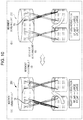
- FIG. 4 illustrates an example of a method for assisting a user by controlling wires disposed so as to cross each other and a method for detecting slacking;
- FIG. 5 illustrates eight wires arranged in the assist device
- FIG. 6 illustrates the movements of the hip joint of a user that can be assisted by the assist device
- FIG. 7 illustrates assistance during flexion of the hip joint of a user
- FIG. 8 illustrates assistance during extension of the hip joint of a user
- FIG. 9 illustrates assistance during abduction of the hip joint of a user
- FIG. 10 illustrates assistance during adduction of the hip joint of the user
- FIG. 11 illustrates assistance during external rotation of the hip joint of a user
- FIG. 12 illustrates assistance during internal rotation of the hip joint of a user
- FIG. 13 illustrates an example of the movement of the upper-body belt unit that is slack at the time of inputting a calibration signal
- FIG. 14 illustrates another example of the movement of the upper-body belt unit that is slack at the time of inputting the calibration signal
- FIG. 15 is a graph illustrating the calibration signal when the input pattern is a pulse wave
- FIG. 16 is a graph illustrating the calibration signal when the input pattern is a triangular wave
- FIG. 17 illustrates calibration signals of the other input patterns
- FIG. 18 illustrates an example of a process for determining the point in time at which calibration is started
- FIG. 19 illustrates a method for determining whether the upper-body belt unit is slack by using a determination unit
- FIG. 20 is a graph illustrating a change in the angular velocity of the upper-body belt unit about the X-axis when a tension greater than or equal to a first threshold value is applied to four of the eight wires by inputting a calibration signal in the form of a pulse wave;
- FIG. 21 illustrates an example of connection points at which the wires are connected to a movement measuring unit
- FIG. 22 illustrates the configuration in which the rotational component of the upper-body belt unit about the X-axis has a more noticeably effect at the time of calibration
- FIG. 23 illustrates the configuration in which the rotational component of the upper-body belt unit about the X-axis has a more noticeably effect at the time of calibration
- FIG. 24 illustrates the rotation of the upper-body belt unit about the Z-axis and a method for rotating the upper-body belt about the Z-axis
- FIG. 25 illustrates the rotation of the upper-body belt unit about the Z-axis and a method for rotating the upper-body belt about the Z-axis
- FIG. 26 illustrates the amount of movement (the displacement) of the upper-body belt unit in the case of detecting slacking of the upper-body belt unit in a normal state
- FIG. 27 illustrates the amount of movement (the displacement) of the upper-body belt unit in the case of detecting slacking of the upper-body belt unit when a user turns right while walking;
- FIG. 28 illustrates an example of presentation of information to the user
- FIG. 29 is a flowchart illustrating the processing flow of the assist device according to the exemplary embodiment.
- FIG. 30 is a block diagram of the configuration of an assist device according to a first modification.
- FIG. 31 illustrates determination of the fit of the upper-body belt unit when the user remains sitting.
- auxiliary device described in Japanese Unexamined Patent Application Publication No. 2014-133121, slacking of the belt that occurs when the auxiliary device is attached is measured by measuring the compression force by moving the attached actuator. Thereafter, the belt is constricted on the basis of the measurement value.
- the auxiliary device does not measure the displacement of the belt position caused by the slack. Consequently, the auxiliary device cannot prevent the positional displacement of the belt caused by slacking of the belt.
- the present inventor conceived the idea of the improvement described below.
- an assist device includes an upper-body belt to be attached to an upper body of a user, a first belt to be attached to a right knee of the user, a second belt to be attached to a left knee of the user, a first wire that couples the upper-body belt to the first belt, a second wire that couples the upper-body belt to the first belt, where the second wire crosses the first wire, a third wire that couples the upper-body belt to the second belt, a fourth wire that couples the upper-body belt to the second belt, where the fourth wire crosses the third wire, a motor coupled to a first end of the first wire, a terminal end of the second wire, a terminal end of the third wire, and a terminal end of the fourth wire, and a drive controller that (i) causes the motor to apply a first tension greater than or equal to a first threshold value to one of the first wire and the second wire at a first time and a second tension greater than or equal to the first threshold value to one of the third wire and the fourth wire at
- the assist device that assists a person with motion by using wires can effectively detect, for example, slacking of the upper-body belt of the assist device.
- the assist device may further include a gyro sensor disposed in the upper-body belt and a controller, where the gyro sensor measures the angular velocity about the vertical axis of the user.
- the gyro sensor may measure the angular velocity when a tension greater than or equal to the first threshold value is applied to one of the first wire and the second wire at a fourth time and one of the third wire and the fourth wire at the fourth time, and the controller may output information indicating that the upper-body belt is slack if the angular velocity is greater than or equal to a second threshold value.
- the assist device that assists a person with motion by using wires can effectively detect, for example, slacking of the upper-body belt of the assist device.
- the assist device can present the result of detection to, for example, the user.
- the assist device can prompt the user to tighten the belt that is slack.
- the user can be assisted by the assist device with more effective assist force.
- first wire may be parallel to the third wire
- second wire may be parallel to the fourth wire.
- the drive controller may causes the motor to apply the third tension to the first wire at the third time and the fourth tension to the third wire at the third time or apply the third tension to the second wire at the third time and the fourth tension to the fourth wire at the third time.
- the assist device may further include a fifth wire that couples the upper-body belt to the first belt, a sixth wire that couples the upper-body belt to the first belt, where the sixth wire crosses the first wire, a seventh wire that couples the upper-body belt to the second belt, and an eighth wire that couples the upper-body belt to the second belt, where the eighth wire crosses the seventh wire.
- the first wire, the second wire, the third wire, and the fourth wire may be located on the front side of the user, and the fifth wire, the sixth wire, the seventh wire, and the eighth wire may be located on the rear side of the user.
- the first wire may be parallel to each of the third wire, the fifth wire, and the seventh wire, and the second wire may be parallel to each of the fourth wire, the sixth wire, and the eighth wire.
- the assist device may assist the user with one of adduction and abduction of a leg of the user by performing any one of the following operations:
- the controller causes the motor to apply a tension greater than or equal to the first threshold value to each of the first wire and the fifth wire,
- the controller causes the motor to apply a tension greater than or equal to the first threshold value to each of the second wire and the sixth wire,
- the controller causes the motor to apply a tension greater than or equal to the first threshold value to each of the third wire and the seventh wire, and
- the controller causes the motor to apply a tension greater than or equal to the first threshold value to each of the fourth wire and the eighth wire.
- the assist device can easily assist the user with adduction or abduction of the legs of the user.
- the assist device may assist the user with one of internal rotation and external rotation of the leg by performing any one of the following operations:
- the controller causes the motor to apply a tension greater than or equal to the first threshold value to each of the first wire and the sixth wire,
- the controller causes the motor to apply a tension greater than or equal to the first threshold value to each of the second wire and the fifth wire,
- the controller causes the motor to apply a tension greater than or equal to the first threshold value to each of the third wire and the eighth wire, and
- the controller causes the motor to apply a tension greater than or equal to the first threshold value to each of the fourth wire and the seventh wire.
- the assist device can easily assist the user with one of internal rotation and external rotation of the legs of the user.
- the first wire has the first end and the second end.
- the motor may be disposed in the upper-body belt.
- the second end may be fixed to the first belt.
- the upper-body belt may include a supporter that slidably supports the first wire, and a first portion of the first wire located between the first end and the supporter may extend in a longitudinal direction of the upper-body belt. When the slacking of the upper-body belt is detected, a force is applies to the first portion by using the motor.
- each of the exemplary embodiments described below is a particular example of the present disclosure.
- a value, a shape, a material, a constituent element, the positions and the connection form of the constituent elements, steps, and the sequence of steps described in the exemplary embodiments are only examples and shall not be construed as limiting the scope of the present disclosure.
- the constituent element that does not appear in an independent claim, which has the broadest scope is described as an optional constituent element.
- the assist device determines whether each of the knee belt units is slack by using the value output from at least one of an acceleration sensor and a gyro sensor and presents information regarding the determination result to the user.
- the assist device having such a configuration is described below.
- FIG. 1 is a schematic illustration of how the assist device 200 according to the present exemplary embodiment is used by a user.
- FIG. 2 is a block diagram of the configuration of the assist device according to the present exemplary embodiment.
- the assist device 200 includes a control unit 100 , an upper-body belt unit 110 serving as an upper-body belt, knee belt units 120 serving as first and second belts, and wires 130 .
- the assist device 200 may further include a presentation unit 140 that presents, to the user, information about the fit of the belts determined by the control unit 100 .
- the control unit 100 includes a signal input unit 101 and a determination unit 102 .
- the control unit 100 is disposed, for example, in the upper-body belt unit 110 .
- the control unit 100 may be disposed in the knee belt unit 120 .
- the signal input unit 101 generates a calibration signal for detecting slacking of the upper-body belt unit 110 .
- the determination unit 102 determines the fit of the upper-body belt unit 110 around the upper body of the user by using the measurement result of a movement measuring unit 113 included in the upper-body belt unit 110 . More specifically, when a first tension is applied to each of the wires 130 by motors 112 , the determination unit 102 determines whether the angular velocity measured by a gyro sensor 115 of the movement measuring unit 113 is greater than or equal to a second threshold value. If, as a result of the determination, the angular velocity measured by the gyro sensor 115 is greater than or equal to the second threshold value, the determination unit 102 outputs information indicating that the upper-body belt unit 110 is slack and/or displaced.
- the upper-body belt unit 110 being slack refers to a situation where the upper-body belt unit 110 is not firmly fixed to the user and, thus, moves relative to the waist of the user when a tension is applied to the upper-body belt unit 110 by the wires 130 .
- the upper-body belt unit 110 being displaced refers to a situation where the upper-body belt unit 110 is rotated about the vertical axis of the upper body, in either one of two rotational directions, from a predetermined position of the waist of the user (the position at which two wires 130 connected to one of the knee belt units 120 are appropriately aligned in the front-rear direction) and is located at a position other than the predetermined position.
- the control unit 100 is implemented by, for example, a processor that executes a predetermined program and a memory that stores the predetermined program. Alternatively, the control unit 100 may be implemented by a dedicated circuit.
- the upper-body belt unit 110 includes a drive control unit 111 , the motors 112 , and a movement measuring unit 113 .
- the upper-body belt unit 110 serves as a harness attached to the upper body (for example, the waist) of the user. Examples of the user's upper body include the waist and the shoulders.
- the upper-body belt unit is pulled in the vertical downward direction (toward the knee belt units).
- the upper-body belt unit is on the waist, slippage of the belt can be prevented by the pelvis.
- the upper-body belt unit In the case of the upper-body belt unit being on the shoulders, the upper-body belt unit can be fixed on the shoulders if the user carries the upper-body belt unit on the shoulders like a backpack, for example.
- the upper-body belt unit 110 has, for example, an elongated band shape.
- the upper-body belt unit 110 is wound around the waist of the user and is kept fastened onto the waist by a fastener, such as a hook and loop fastener. In this manner, the upper-body belt unit 110 is attached to the waist of the user.
- the upper-body belt unit 110 is made of a non-stretchable material that is less likely to be deformed even when tension is applied.
- the drive control unit 111 controls driving of the motors 112 in accordance with a received signal.
- Each of the motors 112 is connected to one of the wires 130 .
- the motors 112 are driven by the drive control unit 111 .
- each of the motors 112 pulls the wire 130 and releases tension on the wire 130 .
- the motors 112 are fixed at predetermined positions of the upper-body belt unit 110 .
- Each of the motors 112 is provided for one of the eight wires 130 (according to the present exemplary embodiment, eight motors 112 ) and is connected to one of the eight wires 130 .
- the upper-body belt unit 110 may have a tubular shape.
- the circumferential length of the tubular shape is longer than the circumferential length of the waist portion of the user.
- the upper-body belt unit 110 in this case has an adjustment mechanism for adjusting the circumferential length to the circumference of the waist of the user.
- An example of the adjustment mechanism is a hook and loop fastener.
- the hook-and-loop fastener is disposed on the outer circumference of the tube such that a part of the hook-and-loop fastener having hooks branch from the outer circumference of the tube, and a part of the hook and loop fastener having loops is arranged on the outer circumference of the tube.
- the movement measuring unit 113 is disposed in the upper-body belt unit 110 and measures the movement of the upper-body belt unit 110 . More specifically, the movement measuring unit 113 includes an acceleration sensor 114 and a gyro sensor 115 .
- the acceleration sensor 114 measures the accelerations in three different directions of the upper-body belt unit 110 , that is, in the X-axis direction, the Y-axis direction, and the Z-axis direction
- the gyro sensor 115 measures the angular velocities around the three different axes, that is, the X-axis, the Y-axis, and the Z-axis.
- the X-axis, the Y-axis, and the Z-axis are defined as illustrated in FIG. 19 .
- the gyro sensor 115 is disposed in the upper-body belt unit 110 to measure the angular velocity in the longitudinal direction of the upper-body belt unit 110 (that is, the circumferential direction of the tubular upper-body belt unit 110 as viewed in the X-axis direction).
- the movement measuring unit 113 transmits the measurement result to the determination unit 102 of the control unit 100 .
- the movement measuring unit 113 may be further disposed in each of the knee belt units 120 and measure the movement of the knee belt units 120 . In this way, the movement measuring unit 113 may measure the movement of the user.
- the X-axis, the Y-axis, and the Z-axis of the gyro sensor 115 may be made coincident with the X-axis, the Y-axis, and the Z-axis of the gyro sensor 115 in the coordinate system of an object to be measured, respectively.
- the X-axis, the ⁇ Y axis, and the ⁇ Z-axis of the acceleration sensor 114 may be made coincident with the X-axis, the Y-axis, and the Z-axis of the acceleration sensor 114 in the coordinate system of an object to be measured, respectively.
- the wires 130 connect the upper-body belt unit 110 to the knee belt units 120 . More specifically, the wires 130 connect the motors 112 and the knee belt units 120 . Four of the wires 130 are disposed for each of the knee belt units 120 , and two of the four wires 130 that cross each other are disposed on the front side of the knee belt units 120 , and the other two that cross each other are disposed on the rear side of the knee belt units 120 . Each of the wires 130 has a first end and a second end. The first end is connected to the motor 112 . When the motor 112 is disposed in the upper-body belt unit 110 , the second end is connected to the knee belt unit 120 .
- the knee belt unit 120 has, for example, an elongated band shape.
- the knee belt unit 120 is attached to the thigh or the upper knee of the user.
- the knee belt unit 120 need not be attached to the hip joint.
- the thigh of a human being has a characteristic that its size gradually increases from the knee to the buttocks. Accordingly, by attaching the knee belt on the upper knee (or the lower thigh), slippage caused by pulling the wires is reduced when the knee belt is tightly attached.
- the assist device can assist the user efficiently.
- the knee belt unit 120 is a member that is wound around the thigh of the user and remains wound around the thigh by a fixing member, such as a hook and loop fastener or any other type of fastener.
- the knee belt units 120 are made of a non-stretchable material that is less likely to be deformed even when a tension is applied in order to support the user.
- the assist device 200 includes two knee belt units 120 each corresponding to one of the two legs of the user. That is, the assist device 200 includes the knee belt unit 120 to be attached to the right knee of the user and the knee belt unit 120 to be attached to the left knee of the user.
- the upper-body belt unit 110 and the knee belt units 120 are made of a non-stretchable material. Accordingly, when each of the knee belt units 120 has no slack and is attached to the leg of the user so as to conform to the shape of the leg, the assist device 200 can easily transfer the support force. Thus, the assist device 200 can assist the user efficiently.
- the presentation unit 140 presents, to the user, the determination result of the determination unit 102 of the control unit 100 . That is, the presentation unit 140 presents, to the user, at least one of whether the knee belt unit 120 is slack and whether the knee belt unit 120 is displaced.
- FIG. 3 illustrates an example of an information presentation method employed when the user uses the assist device.
- the presentation unit 140 presents to the user that the upper-body belt unit 110 is slack.
- the presentation unit 140 may be formed from a vibration actuator (not illustrated) that is disposed on the upper-body belt unit 110 and that informs the user that the upper-body belt unit 110 is slack by using vibration.
- the presentation unit 140 may be formed from a vibration actuator that is disposed on the knee belt unit 120 and that informs the user that the upper-body belt unit 110 is slack by using vibration.
- the presentation unit 140 may display, on a display 301 of a mobile terminal 300 carried by the user, such as a smartphone, an image or a text message indicating that the upper-body belt unit 110 is slack.
- FIG. 4 illustrates an example of a method for assisting a user by controlling wires disposed so as to cross each other and a method for detecting the slack.
- the assist device 200 assists the user with motion. For example, for a time period of 0.3 seconds after the start of the swing phase, two of the wires 130 disposed on the front side of the user for the knee belt unit 120 attached to the leg in the swing phase are pulled at the same time. In this manner, the assist device 200 assists the user with flexion of the hip joint of the leg.
- the assist device 200 has eight wires 130 disposed so as to be controllable in total.
- Two of the wires 130 are arranged to cross each other on each of the right and left legs and on each of the front and rear sides of the legs. Accordingly, while the user is walking, the assist device 200 can assist the user with flexion and the extension of the hip joint by alternately pulling the two wires 130 on each of the left and right legs and on each of the front and rear side of the legs. Note that the assist device 200 need not simultaneously pull the two wires 130 disposed to cross each other on each of the legs on each of the front and rear side. For example, the assist device 200 may select one of the two wires 130 disposed on the front side of a given leg and select one of the two wires 130 disposed on the rear side of the leg. In this manner, the assist device 200 may assist the user with movement other than flexion and the extension (e.g., abduction, adduction, external rotation, or internal rotation).
- abduction, adduction, external rotation, or internal rotation e.g., abduction, adduction, external rotation, or internal rotation.
- the upper-body belt unit 110 moves and, thus, the entire assist force is not applied.
- the upper-body belt unit 110 stops at the iliac bone, the vertical acceleration of the user is less likely to vary greatly. Instead, in the upper-body belt unit 110 , by applying a tension that promotes rotation in the left-right rotational direction via the wires 130 , the angular velocity in the rotational direction is readily changed and, thus, the upper-body belt unit 110 easily comes off if the upper-body belt unit 110 is slack. As illustrated in FIG.
- the assist device 200 for example, to detect the displacement, among two wires 130 disposed on the front side of each of the legs of the user, by pulling the wires 130 that extend in the same direction (waist: right ⁇ knee: left) (one end on the waist is located on the right, and the other end on the knee is located on the left), a variation in angular velocity of the upper-body belt unit 110 about the X-axis occurs. Thus, slacking of the upper-body belt unit 110 can be detected.
- a calibration signal is input.
- predetermined ones of the wires 130 are pulled.
- the upper-body belt that is slack is rotated.
- the variations of the acceleration and the speed are evaluated by using the acceleration sensor 114 and the gyro sensor 115 disposed in the upper-body belt unit 110 .
- the assist device 200 detects whether the upper-body belt unit 110 is displaced from a predetermined attachment position by evaluating the angular velocity detected by the gyro sensor 115 . That is, if, as a result of input of the calibration signal, the assist device 200 determines that the upper-body belt unit 110 is displaced from the predetermined attachment position, the assist device 200 determines that the upper-body belt unit 110 is slack.
- the assist device 200 detects whether the upper-body belt unit 110 is slack and outputs the detection result. Accordingly, the user can easily notice that the upper-body belt unit 110 is slack after, for example, the user wears the assist device 200 by themselves or after the user wears the assist device 200 and operates the assist device 200 for a while. Consequently, by re-tightening the upper-body belt unit 110 , the user can be more effectively assisted in moving both legs by the assist device 200 .
- the signal input unit 101 determines a signal for detecting whether the upper-body belt unit 110 is slack or a signal for selecting a wire to be used for assistance during walking and sends the determined signal to the drive control unit 111 . More specifically, at the time of calibration, the signal input unit 101 selects the wires 130 to be pulled in order to rotate the upper-body belt unit 110 and determines the tension to be applied to the selected wires 130 . Thereafter, the signal input unit 101 determines the rotation angle of the motor for generating the tension as an input signal and sends the signal to the drive control unit 111 .
- the signal input unit 101 identifies the walking phase by using a given point in time during walking (e.g., the time point when the heel contacts the ground) and determines a signal for pulling the wires in directions in which the hip joint of the user is flexed and extended in accordance with the identified walking phase. In this manner, the upper-body belt unit 110 assists the user with walking.
- FIG. 5 illustrates the eight wires arranged in the assist device.
- the assist device 200 four wires 130 are connected between the upper-body belt unit 110 and each of the right and left knee belt units 120 (at four places in total) such that two of the wires 130 are disposed on the front side and the other two on the rear side and the two wires on each of the front and rear sides cross each other.
- the naming rule of the wires is “right/left leg-front/rear of the leg-attachment position of the upper-body belt unit”.
- RF_right represents the wire that is disposed for the right leg (Right) on the front side (Front) and is attached to the right side (right) of the upper body belt.
- LR_left represents the wire that is disposed for the left leg (Left) on the rear side (Rear) and is attached to the left side (left) of the upper body belt.
- the eight wires, every two of which cross each other, are labeled as “RF_right”, “RF_left”, “RR_right”, “RR_left”, “LF_right”, “LF_left”, “LR_right”, and “LR_left”.
- the assist device 200 includes first to fourth wires.
- the first wire connects the upper-body belt unit 110 to the knee belt unit 120 that corresponds to the right knee.
- the second wire connects the upper-body belt unit 110 to the knee belt unit 120 that corresponds to the right knee and that crosses the first wire.
- the third wire connects the upper-body belt unit 110 and the knee belt unit 120 that corresponds to the left knee.
- the fourth wire connects the upper-body belt unit 110 to the knee belt unit 120 that corresponds to the left knee and that crosses the third wire.
- the first to fourth wires are disposed on the front face (front side) of the user.
- the assist device 200 further includes fifth to eighth wires.
- the fifth wire connects the upper-body belt unit 110 to the knee belt unit 120 that corresponds to the right knee.
- the sixth wire connects the upper-body belt unit 110 and the knee belt unit 120 that corresponds to the right knee and that crosses the first wire.
- the seventh wire connects the upper-body belt unit 110 to the knee belt unit 120 corresponding to the left knee.
- the eighth wire connects the upper-body belt unit 110 to the knee belt unit 120 that corresponds to the left knee and that crosses the third wire.
- the fifth to eighth wires are disposed on the rear face (rear side) of the user.
- first wire, the third wire, the fifth wire, and the seventh wire are disposed parallel to one another.
- first wire is “RF_right”
- third wire is “LF_right”
- fifth wire is “RR_right”
- seventh wire is “LR_right”.
- the second wire, the fourth wire, the sixth wire, and the eighth wire are disposed parallel to one another.
- the second wire is “RF_left”
- the fourth wire is “LF_left”
- the sixth wire is “RR_left”
- the eighth wire is “LR_left”.
- parallel used herein is not intended to mean “strictly parallel”. That is, the wires are parallel to one another if the wires are oriented in the same direction with respect to the X-axis direction.
- FIG. 6 illustrates the types of movement of the hip joint of the user that can be assisted by the assist device 200 .
- FIG. 6( a ) illustrates flection and extension to move the thigh of the user in the forward-rearward direction.
- the movement to move the thigh in the forward direction is called flexion of the hip joint, and the movement to move the thigh in the rearward direction is referred to as extension of the hip joint.
- FIG. 6( b ) illustrates abduction and adduction which move the thighs of the user in the right-left direction.
- abduction “moving the thighs outwardly” in the right-left direction of the user (the right side in the case of the right leg, and the left side in the case of the left leg)
- adduction “moving the thighs inwardly” in the right-left direction of the user (the left side in the case of the right leg, and the right side in the case of the left leg) is called adduction.
- FIG. 6( c ) illustrates external rotation and internal rotation to rotate the thigh of the user about the vertical axis of the user.
- “rotating the thigh of the user externally” (right turn in the case of the right leg, and left turn in the case of the left leg) is called external rotation
- “rotating the thigh of the user internally” (in the left turn in the case of the right leg, and the right turn in the case of the left leg) is called the internal rotation.
- the assist device When assisting the user with walking, the assist device assists the user with the following movements in the following ranges:
- Assistance in the adduction direction 60% to 100% (assistance is not needed during normal walking)
- the assist signals input from the signal input unit 101 are sequentially described first.
- FIG. 7 illustrates the case of assist in the flexion direction of the hip joint of the user.
- FIG. 7( a ) illustrates the assist in the flexion direction of the right hip joint
- FIG. 7( b ) illustrates the assist in the flexion direction of the left hip joint.
- a first threshold for example, 100 N
- the tension of each of the wires “LF_right” and “LF_left” is set to a value greater than or equal to the first threshold value.
- FIG. 8 illustrates the case of assist in the extension direction of the hip joint of the user.
- each of the tensions of the wires “RR_right” and “RR_left” is set to a value greater than or equal to a first threshold value (for example, 100 N).
- a first threshold value for example, 100 N
- each of the tensions of the wires “LR_right” and “LR_left” is set to the value greater than or equal to a first threshold value.
- the motor 112 applies a tension that is greater than or equal to the first threshold value to one of the first wire and the second wire and one of the third wire and the fourth wire at different points in time.
- the term “different points in time” used herein refers to points in time that make the time periods during which the tension greater than or equal to the first threshold is applied do not overlap each other.
- the condition that the tension greater than or equal to the first threshold value is applied to one of the first wire and the second wire and one of the third wire and the fourth wire at different points in time is equivalent to the condition that a tension greater than or equal to the first threshold value is not applied to one of the third wire and the fourth wire for the period of time during which a tension greater than or equal to the first threshold value is being applied to one of the first wire and the second wire and a condition that a tension greater than or equal to the first threshold value is not applied to one of the first wire and the second wire for the period of time during which a tension greater than or equal to the first threshold value is being applied to one of the third wire and the fourth wire.
- the effect of assistance during walking can be further improved.
- FIG. 9 illustrates the case of assistance of the abduction of the hip joint of the user.
- the tension of each of the wires “RF_right” and “RR_right” is set to a value greater than or equal to the first threshold value.
- the tension of each of the wires “LF_left” and “LR_left” is set to a value greater than or equal to the first threshold value.
- FIG. 10 illustrates the case of assistance during adduction of the hip joint of the user.
- the tension of each of the wires “RF_left” and “RR_left” is set to a value greater than or equal to the first threshold value.
- the tension of each of the wires “LF_right” and “LR_right” is set to a value greater than or equal to the first threshold value.
- the drive control unit 111 provides assistance during adduction or abduction of the leg of the user by performing any one of the following operations:
- FIG. 11 illustrates the case of assistance during external rotation of the hip joint of the user.
- FIG. 12 illustrates the case of assistance during internal rotation of the hip joint of the user.
- the tension of each of the wires “RF_right” and “RR_left” is set to a value greater than or equal to the first threshold value.
- the tension of each of the wires “LF_left” and “LR_right” is set to a value greater than or equal to the first threshold value.
- the tension of each of the wires “RF_left” and “RR_right” is set to a value greater than or equal to the first threshold value.
- the tension of each of the wires “LF_right” and “LR_left” is set to a value greater than or equal to the first threshold value.
- the drive control unit 111 provides assistance during internal rotation or external rotation of the leg of the user by performing any one of the following operations:
- the tension of the selected wire is set to a value greater than or equal to the first tension (for example, 100 N).
- the tension of each of the other wires may be 0 N or a value less than or equal to a third threshold (for example, one tenth of the first threshold value).
- the tension of each of the selected two wires has been set to the same value (100 N), the tensions of the two wires need not be the same.
- the tension of the wire on the front side when the tension of the wire on the front side is 100 N for assistance of abduction/adduction or internal rotation/external rotation, the tension of the wire on the rear side may be doubled to 200 N.
- the moment arm of the hip joint on the front side differs from that on the rear side, the expected torque may not be output when the wires are pulled with the same tension.
- the balance between the tensions of the wires on the front side and the rear side may be adjusted according to individuals.
- an assist force is mainly provided in the flexion direction and extension direction, and an assist force is provided in the abduction direction, the adduction direction, the external rotation direction, and internal rotation direction in accordance with the assist force to be applied in the stance phase or the swing phase.
- the assist device can assist the user with walking more effectively.
- Input of the calibration signal for measuring the slack of the upper-body belt unit 110 is described below.
- the calibration in the assist device 200 is conducted to detect slacking of the upper-body belt unit 110 .
- the assist device 200 determines whether the upper-body belt unit 110 is slack by using the rotation of the upper-body belt unit 110 .
- FIG. 13 illustrates an example of the movement of the upper-body belt unit that is slack at the time of inputting a calibration signal.
- the movement of the upper-body belt unit 110 in the vertical direction is stopped at the ilium of the user and, thus, the upper-body belt unit 110 is substantially stationary. Accordingly, if the wires 130 are pulled such that the upper-body belt unit 110 rotates in the rotation direction around the waist, the upper-body belt unit 110 moves in the rotation direction in which the upper-body belt unit 110 is pulled. Consequently, the movement of the upper-body belt unit 110 can be measured by using the acceleration sensor 114 and the gyro sensor 115 .
- FIG. 13( a ) illustrates all of the wires each having a tension of 0 N.
- a calibration signal is input to rotate the upper-body belt unit 110 that is slack in the counterclockwise direction (the left rotation direction).
- the tension of each of the wires “RF_right”, “RR_left”, “LF_right”, and “LR_left” is set to a value that is greater than or equal to the first threshold value (for example, 100 N).
- the first threshold value for example, 100 N
- the tension of the wire other than the wire having a tension set to the value greater than or equal to the first threshold value may be set to 0 N or a tension less than or equal to a third threshold value (for example, one tenth of the first threshold value).
- FIG. 14 illustrates another example of the movement of the upper-body belt unit that is slack at the time of inputting the calibration signal.
- FIG. 14 illustrates the case in which a calibration signal is input so that the wires are pulled to rotate the upper-body belt unit 110 clockwise (in the right rotation direction).
- the tension of each of the wires “RF_left”, “RR_right”, “LF_left”, and “LR_right” is set to a value greater than or equal to the first threshold value (for example, 100 N).
- the tension of the wire other than the wire having a tension set to a value greater than or equal to the first threshold value may be set to 0 N or a value less than or equal to the third threshold value (for example, one tenth of the first threshold value).
- one of the wires connected to the right and left knee belt units 120 is selected, and a total of four wires are pulled at the same time.
- the upper-body belt unit 110 is rotated, and slacking of the upper-body belt unit 110 is detected. That is, when detecting slacking of the upper-body belt unit 110 , the drive control unit 111 controls the motor 112 to apply a tension greater than or equal to the first threshold to one of the first wire and the second wire and one of the third wire and the fourth wire at the same time.
- the drive control unit 111 when detecting slacking of the upper-body belt unit 110 , applies a tension greater than or equal to the first threshold value to the first wire and the third wire at the same time. Alternatively, when detecting slacking of the upper-body belt unit 110 , the drive control unit 111 applies a tension greater than or equal to the first threshold value to the second wire and the fourth wire at the same time.
- the term “same time” used here means that two periods of time during which the tensions that are greater than or equal to the first threshold value are being applied overlap. That is, the condition that the tension greater than or equal to the first threshold value is applied to one of the first wire and the second wire and one of the third wire and the fourth wire at the same time is equivalent to the condition that the period of time during which a tension greater than or equal to the first threshold value is being applied to one of the first wire and the second wire overlaps the period of time during which a tension greater than or equal to the first threshold value is being applied to one of the third wire and the fourth wire overlap each other. That is, if the periods of time during which tensions each greater than or equal to the first threshold value are applied to different wires overlap, it can be said that the tensions are applied at the same time.
- the drive control unit 111 applies a tension greater than or equal to the “first threshold value” to each of the wires by driving the motor 112 . That is, if an extra tension is applied to the wire by the operation performed by the user and, thus, a tension greater than or equal to the “first threshold value” is applied to the wire, it is considered that the drive control unit 111 does not apply a tension greater than or equal to the first threshold to the wire.
- FIGS. 15 and 16 are graphs illustrating examples of a calibration signal.
- FIG. 15 is a graph illustrating a calibration signal when an input pattern is a pulse wave.
- FIG. 16 is a graph illustrating a calibration signal when the input pattern is a triangular wave.
- the input pattern of the calibration signal may be a pulse wave or a triangular wave.
- “w” represents the signal width
- “h” represents the input tension (the magnitude of a first tension).
- the operation performed when a pulse wave is used as an input pattern of a calibration signal is described first. If the input tension h is too small, it is difficult to move the upper-body belt unit 110 sufficiently to accurately measure the slack of the upper-body belt unit 110 even when the upper-body belt unit 110 is slack. In contrast, if the input tension h is too large, it is likely to greatly move the upper-body belt unit 110 even when the upper-body belt unit 110 is fixed to the thigh of the user so as to sufficiently assist the user with movement of the two legs of the user.
- the magnitude of the input tension h may be determined so as to be within a predetermined range (for example, a range of 50 N to 400 N) that is applied when assisting the user with movement of the two legs of the user.
- a predetermined range for example, a range of 50 N to 400 N
- the control unit 100 can determine that the upper-body belt unit 110 is slack and, thus, can determine that the user needs to tighten the upper-body belt unit 110 again.
- the pulse wave is an input pattern in which the signal steeply rise and fall. Accordingly, if the signal width w is larger than a predetermined threshold value, for example, 0.1 seconds, the upper-body belt unit 110 can be moved so that slacking of the upper-body belt unit 110 can be accurately determined. However, to quickly detect slacking of the upper-body belt unit 110 , the signal width w may be reduced so as not to be too large. Consequently, according to the present exemplary embodiment, when the input pattern of the calibration signal is a pulse wave, the signal width w can be set to a value in the range of, for example, 0.1 to 1.0 seconds.
- the input tension h may be determined so as to be within a range that is substantially the same as the predetermined range that is applied when assistance is provided during movement of the two legs of the user (for example, a range of 50 N to 400 N).
- the influence of the signal width w on the upper-body belt unit 110 differs according to the value of the signal width w. For example, when the signal width w is as small as about 0.2 seconds, the time period from the time the input tension rises to h until the tension drops to the original value 0 is short. Accordingly, the signal pattern is close to a step input like a pulse wave, and the upper-body belt unit 110 operates in a similar manner to the operation for the pulse wave.
- the tension of the wire gradually linearly increases and decreases and, thus, the drive control unit 111 can control the motor 112 without any delay. That is, when the upper-body belt unit 110 is slack and if a calibration signal having the signal width w greater than 1.0 second is input to the drive control unit 111 , the upper-body belt unit 110 is gradually pulled by the wire 130 since the rate of increase in the tension by the wire 130 is small. Thus, the upper-body belt unit 110 is gradually displaced from its original position. Subsequently, the input tension h decreases from the turning-back point, which corresponds to the apex of the triangular wave of the calibration signal. As a result, it is less likely for the upper-body belt unit 110 to return to the original position due to the reaction of the applied tension than in the case where a large tension is instantly applied to the upper-body belt unit 110 .
- the determination unit 102 of the control unit 100 calculates the amount of displacement of the upper-body belt unit 110 (the amounts of displacement in the X-axis direction, the Y-axis direction, and the Z-axis direction and the amounts of rotation about the X-axis, the Y-axis, and the Z-axis) from the acceleration and the angular velocity detected by the movement measuring unit 113 attached to the upper-body belt unit 110 .
- the determination unit 102 calculates the displacement of the upper-body belt unit 110 from its original position. If the calculated displacement exceeds a predetermined threshold value (for example, 1 cm), the determination unit 102 may determine that the upper-body belt unit 110 is slack.
- the processing is not limited thereto.
- the above-described two types of input patterns of the calibration signal may be input, and slacking of the upper-body belt unit 110 may be detected by using a combination of measurement results from the movement measuring unit 113 .
- the movement of the upper-body belt unit 110 is examined. At this time, if it is determined that the upper-body belt unit 110 is slack twice, it is difficult to determine whether the upper-body belt unit 110 is actually slack.
- the control unit 100 inputs a calibration signal having an input pattern of a triangular wave and having a large signal width w and obtains a value measured and returned by the movement measuring unit 113 . If the return value of the amount of displacement of the upper-body belt unit 110 obtained when the calibration signal is input is greater than a predetermined threshold value (for example, 1 cm), it may be determined that the upper-body belt unit 110 is slack.
- a predetermined threshold value for example, 1 cm
- FIG. 17( a ) is a graph illustrating a calibration signal of an input pattern in which the tension linearly increases and, thereafter, decreases stepwise.
- FIG. 17( b ) is a graph illustrating a calibration signal of an input pattern in which the tension falls stepwise.
- FIG. 17( c ) is a graph illustrating the calibration signal of the input pattern in which the tension increases stepwise and, thereafter, linearly decreases.
- FIG. 17 ( d ) is a graph illustrating a calibration signal of an input pattern in which the tension increases stepwise.
- the drive control unit 111 is provided in the upper-body belt unit 110 .
- the drive control unit 111 drives the motor 112 in accordance with a signal received from the signal input unit 101 . More specifically, the drive control unit 111 calculates the necessary rotational speed of the motor 112 from the input tension indicated by the signal received from the signal input unit. Thereafter, the drive control unit 111 rotates the motor 112 at the calculated rotational speed required. If the signal received from the signal input unit 101 indicates the required rotational speed of the motor 112 , the drive control unit 111 may rotate the motor 112 at the required rotational speed indicated by the signal.
- the movement measuring unit 113 is provided in the upper-body belt unit 110 .
- the movement measuring unit 113 measures the movement of the upper-body belt unit 110 and transmits time-series data that is the measurement result of the measured movement to the determination unit 102 . More specifically, the movement measuring unit 113 includes the acceleration sensor 114 and the gyro sensor 115 .
- the movement measuring unit 113 measures the movement of the upper-body belt unit 110 when the upper-body belt unit 110 is pulled by the motor 112 via the wires 130 .
- the displacement caused by the movement when the upper-body belt unit 110 is pulled by the wires 130 increases, as compared with in the case where the upper-body belt unit 110 is sufficiently tightly attached to the thigh.
- a force is applied to the upper-body belt unit 110 in the rotation direction when the upper-body belt unit 110 is pulled by the wire 130 , for example. How to select one of the values acquired by the movement measuring unit 113 to determine the fit of the upper-body belt unit 110 is described in more detail below.
- the knee belt units 120 are attached to the user's knees without slack in order to detect slacking of the upper-body belt unit 110 .
- the configuration is not limited thereto.
- a movement measuring unit having the same configuration as that of the movement measuring unit 113 may be provided in each of the knee belt units 120 , and slacking of each of the knee belt units 120 may be further detected.
- slacking of each of the knee belt units 120 may be detected first. After tightly attaching the knee belt units 120 to the user, a calibration signal may be input again to detect slacking of the upper-body belt unit 110 .
- slacking may be detected by using, for example, the condition that the tension of each of the wires “RF_right”, “RF_left”, “LF_right”, and “LF_left” is greater than or equal to the first threshold (100 N).
- slacking may be detected by using the condition that the tension of each of only the wires on the rear side, that is, the wires “RR_right”, “RR_left”, “LR_right”, “LR_left” is greater than or equal to the first threshold (100 N).
- slacking of the upper-body belt unit 110 may be detected by using the above-described method. As described above, by detecting slacking of the knee belt unit 120 first and, subsequently, detecting slacking of the upper-body belt unit 110 , the user can wear the assist device 200 on the body more reliably and, thus, can be assisted more effectively.
- the assist device 200 is used to assist the user with motion, such as, walking.
- the assist device 200 needs to determine whether the upper-body belt unit 110 is slack immediately after the assist device 200 is attached to the user or after the assist device 200 is operated for a while. That is, the assist device 200 needs to make the determination when the movement of the user stops.
- the movement measuring unit 113 determines from the values measured by the acceleration sensor 114 and the gyro sensor 115 whether the movement of the user stops and transmits, to the signal input unit 101 , a start signal indicating that calibration is to be started.
- FIG. 18 illustrates an example of the process of determining the point in time at which the calibration is started.
- the abscissa represents the time
- the ordinate represents the acceleration obtained by combining the acceleration components in the X-axis direction, the Y-axis direction, and the Z-axis direction.
- FIG. 18 illustrates an example of a change in acceleration obtained by combining the acceleration components in the X-axis direction, the Y-axis direction, and the Z-axis direction acquired by the movement measuring unit 113 when the user who is walking stops, for example, in front of a traffic signal. As illustrated in FIG.
- the movement measuring unit 113 may determine that the movement of the user stops and transmits, to the signal input unit 101 , the start signal. That is, the movement measuring unit 113 further determines whether the acceleration obtained by combining the acceleration components in the X-axis direction, the Y-axis direction, and the Z-axis direction measured by the acceleration sensor 114 included in the upper-body belt unit 110 is less than or equal to a second threshold value.
- the movement measuring unit 113 determines whether the point in time to start calibration is reached. Thereafter, if the acceleration obtained by combining the acceleration components in the X-axis direction, the Y-axis direction, and the Z-axis direction is smaller than or equal to the second threshold value, the movement measuring unit 113 transmits, to the signal input unit 101 , a start signal indicating that calibration is to be started.
- the predetermined period of time T is set to 2 seconds, and the second threshold value H of a change in the acceleration obtained by combining the acceleration components in the X-axis direction, the Y-axis direction, and the Z-axis direction is set to 0.3 m/s 2 .
- the values are not limited thereto. Since it is only required to distinguish a user that is moving, such as walking, from a user that is stationary, the human walking cycle may be measured by the acceleration sensor 114 . Thereafter, the predetermined period of time T may be set to twice the walking period. For example, when the walking cycle of the user is 1.5 seconds, the predetermined period of time T may be set to 3 seconds.
- the second threshold value H of a change in the acceleration obtained by combining the acceleration components in the X-axis direction, the Y-axis direction, and the Z-axis direction may be determined on the basis of a change in the acceleration obtained by combining the acceleration components of the walking motion of the user in the X-axis direction, the Y-axis direction, and the Z-axis direction.
- the second threshold value H may be set to one-third of the change in acceleration obtained by combining the acceleration components in the X-axis direction, the Y-axis direction, and the Z-axis direction of the walking motion of the user.
- the movement measuring unit 113 determines that calibration is to be started.
- the time of starting calibration is not limited thereto.
- a start button for starting the calibration may be provided on the assist device 200 , and the user may press the start button to start the calibration.
- the start button may be provided on the control unit 100 or the upper-body belt unit 110 , and the user may press the button by themselves to detect slacking of the knee belt when, for example, waiting for a traffic light.
- the movement measuring unit 113 is configured to include the acceleration sensor 114 and the gyro sensor 115 and a dedicated circuit and a processor that make the determination. If the above determination is not needed, the movement measuring unit 113 is configured to include the acceleration sensor 114 and the gyro sensor 115 without including a dedicated circuit and a processor.
- the determination unit 102 is a unit that determines from the measurement result transmitted from the movement measuring unit 113 whether the upper-body belt unit 110 attached to the user is slack.
- the determination unit 102 is a unit that detects the displacement of the attachment position of the upper-body belt unit 110 attached to the user. More specifically, the determination unit 102 receives a calibration start signal from the signal input unit 101 and enters a determination mode for detecting slacking of the upper-body belt unit 110 . After entering the determination mode, the determination unit 102 receives the values of the acceleration and the angular velocity from the movement measuring unit 113 and determines whether the upper-body belt unit 110 is slack.
- a method for detecting slacking of the upper-body belt unit 110 by using the determination unit 102 is described below.
- the upper-body belt unit 110 that is slack pulls the knee belt unit 120 , sliding of the upper-body belt unit 110 in the vertical direction is prevented by the ilium of the user. Accordingly, even when the upper-body belt unit 110 is slack (not firmly attached), the upper-body belt unit 110 is less likely to move in the vertical direction. In contrast, if a force is applied to the upper-body belt unit 110 that is slack in the rotation direction around the waist, the upper-body belt unit 110 rotates and is displaced.
- the vertical direction of the user is defined as the X-axis direction
- the right-left direction of the user is defined as the Y-axis direction
- the front-rear direction of the user is defined as the Z-axis direction.
- the upward X-axis direction is a positive direction.
- the left Y-axis direction as viewed from the user is a positive direction
- the frontward Z-axis direction of the user is a positive direction.
- the wires 130 are disposed in substantially the X-Y plane so that every two wires cross each other obliquely in the X-Y plane. Accordingly, when the knee belt unit 120 that is slack is pulled, the component of the tension in the Y-axis direction of each of the wires acts on the upper-body belt unit 110 . Thus, the acceleration in the Y-axis direction of the upper-body belt unit 110 varies. In addition, since the upper-body belt unit 110 rotates about the X-axis, the angular velocity about the X-axis varies most among the angular velocities about the three axes. FIG. 20 illustrates an example of the angular velocity about the X-axis.
- the abscissa represents the time
- the ordinate represents the angular velocity about the X-axis. Note that in the data illustrated in FIG. 20 , the tension of each of the four wires “RF_right”, “RR_left”, “LF_right”, and “LR_left” is set to the first threshold value (100 N).
- the alternate long and short dash line (TIGHT) in the graph indicates a variation of the angular velocity when the upper-body belt unit 110 is fastened tightly
- the solid line (SLACK) indicates a variation of the angular velocity when the upper-body belt unit 110 is slack.
- the variation of the angular velocity about the X-axis is larger when the upper-body belt unit 110 is slack than when the upper-body belt unit 110 is fastened tightly.
- a predetermined threshold value for example, 0.8 rad/s 2
- the determination unit 102 detects the angular velocity about the X-axis and determines whether the upper-body belt unit 110 is slack.
- a determination method is not limited thereto. For example, if each of the change in acceleration in the Y-axis direction and the change in angular velocity about the X-axis is greater than or equal to a corresponding predetermined threshold value, the determination unit 102 may determine that the attachment position of the upper-body belt unit 110 is displaced and, thus, determine that the upper-body belt unit 110 is slack.
- the determination unit 102 may determine whether the attachment position of the upper-body belt unit 110 is displaced and, thus, whether the upper-body belt unit 110 is slack.
- the determination unit 102 may determine that the attachment position of the upper-body belt unit 110 is displaced and, thus, the upper-body belt unit 110 is slack. As a result, the determination unit 102 can have the robustness of slack detection and can determine whether the upper-body belt unit 110 is slack more accurately.
- the determination unit 102 may determine that the attachment position of the upper-body belt unit 110 is displaced and, thus, the upper-body belt unit 110 is slack. Note that a method for detecting slacking is not limited thereto.
- the determination unit 102 may determine that the attachment position of the upper-body belt unit 110 is displaced and, thus, the upper-body belt unit 110 is slack.
- At least one of a pair consisting of the value of the first tension of the calibration signal and the predetermined threshold value of the change in acceleration in the Y-axis direction, a pair consisting of the value of the first tension of the calibration signal and the predetermined threshold value of the change in angular velocity about the X-axis, and a pair consisting of the value of the first tension of the calibration signal and the predetermined threshold value of the change in angular velocity about the Z-axis may be set according to the user. Thereafter, the determination unit 102 may determine whether the attachment position of the upper-body belt unit 110 is displaced, that is, the upper-body belt unit 110 is slack. The value of the first tension may differ according to users.
- the assist device 200 may include a reception unit that receives the preference from the user.
- the reception unit is implemented by, for example, an input interface (IF), such as a button, a switch, an input key, or a touch panel, a processor, and a memory.
- IF input interface
- the tightness and/or the fit of the upper-body belt unit 110 differ according to individual. Accordingly, when using the assist device 200 for the first time and/or at predetermined intervals after the user starts to use the assist device 200 , the user may tighten the upper-body belt unit 110 by themselves and store the value of the change in acceleration and the value of the change in angular velocity of the upper-body belt unit 110 . Thereafter, by using the stored values, the user may set the predetermined threshold values used in the above-described determination as to whether the upper-body belt unit 110 is slack.
- the predetermined threshold value may be set to a value that is less than an initially set value (a standard value) by, for example, about 5 to 20%.
- the predetermined threshold value may be set to a value that is greater than the standard value by about 5 to 20%.
- the assist device may further include a reception unit that receives a value set by the user and a storage unit that stores the set value received by the reception unit.
- the control unit may adjust the first threshold value in accordance with the set value stored in the storage unit and output, as the information, the result of determination made by using the adjusted first threshold value.
- the slack of the upper-body belt unit 110 can be appropriately determined by setting the predetermined threshold value used to determine the slack of the upper-body belt unit 110 to a different value in accordance with the above-described different preference or tightness.
- the present exemplary embodiment basically, by applying the first tension to each of four particular wires disposed in front right, front left, rear right, and rear left positions, slacking of the upper-body belt unit 110 can be detected. At this time, by mainly measuring the change in the angular velocity of rotation of the upper-body belt unit 110 around the waist caused by the tensions of the wires, the slack of the upper-body belt unit 110 can be determined noticeably.
- the connection points of the wires 130 and a technique for fixing the wires 130 are described below.
- connection points and the fixing technique of the wires 130 are effective to noticeably measure the velocity component in the rotational direction around the vertical axis of the user and the angular velocity component in the rotation direction around the axis of the user extending in the front-rear direction.
- the movement measuring unit 113 that calculates the rotational component about the X-axis and the connection points of the wires 130 are described first.
- FIG. 21 illustrates an example of the connection points at which the wires 130 are connected to the movement measuring unit 113 .
- FIG. 21 illustrates an example of the upper-body belt unit 110 rotated in a counterclockwise direction.
- the wire “RF_right” can have a predetermined angle ⁇ (for example, ⁇ is greater than or equal to 10 degrees and less than 45 degrees) with respect to the X-axis. If the predetermined angle ⁇ is too small, it is difficult to rotate the upper-body belt unit 110 during calibration, as described above.
- the wires may be arranged such that the attachment angle of the wires arranged to cross each other meets the condition of the upper limit and the lower limit of the predetermined angle ⁇ defined as described above.
- the attachment angle of the wire is set to the predetermined angle ⁇ (an angle greater than or equal to 10 degrees and less than 45 degrees), the attachment angle is not limited thereto.
- the attachment angle of the wire varies according to the circumference of the waist and the circumference of the knee of the user. Accordingly, for example, the assist device 200 may be configured such that the attachment position of the wire can be adjusted each time the user wears the assist device 200 , the attachment position of the wire can be changed, and the angle can be made the same according to the user.
- the attachment position of the wire may be determined by, for example, assisting the user with flexion and extension after adjusting the angle and determining whether the user is assisted and by inputting a calibration signal when the upper-body belt unit 110 is slack and determining whether the upper-body belt unit 110 rotates.
- a technique illustrated in FIGS. 22 and 23 may be employed. That is, the wire 130 may be led from the knee belt unit 120 so as to pass through a ring-shaped supporting unit 161 provided on an inner wear item 160 and be attached to a fixed point 162 located on the upper-body belt unit 110 on the right rotation side of the supporting unit 161 .
- the wires “RF_right”, “LF_right”, “RR_left”, and “LR_left” may be connected to the upper-body belt unit 110 as illustrated in FIG. 22 . That is, the wires are led from the knee belt units 120 with tension at a predetermined angle so as to pass over the inner wear item 160 . Thereafter, the wires are continuously led to the right of the user and are fixed to the upper-body belt unit 110 . In this manner, by pulling the predetermined wires at the time of calibration, a more force is applied in the rotation direction about the X-axis. If the upper-body belt unit 110 is slack, the rotational displacement about the X-axis increases.
- FIG. 23 illustrates a case where the upper-body belt unit is rotated clockwise.
- the wires “RF_left”, “LF_left”, “RR_right” and “LR_right” are pulled.
- the following technique may be employed. That is, the wires are led from the knee belt units 120 with tension at a predetermined angle so as to pass over the inner wear item 160 . Thereafter, the wires are continuously led to the left of the user and are fixed to the upper-body belt unit 110 .
- the supporting unit 161 and a supporting unit 163 are located at the same height as the fixed point 162 and a fixed point 164 (that is, the positions in the X-axis direction are the same), the largest force can be applied to the upper-body belt unit 110 in the longitudinal direction. For this reason, the position of the ring-shaped supporting units 161 and 163 and the position of the fixed points 162 and 164 in the X-axis direction may be set to the same position.
- Examples of the structure of the supporting units 161 and 163 include the above-described annular ring, a pulley, and a rail. That is, the supporting units 161 and 163 slidably support the wires.
- a force in an oblique direction between the upper-body belt unit 110 and the knee belt unit 120 and a force in the longitudinal direction of the upper-body belt unit 110 are produced at the via point. While above description has been given with reference to the via point being a ring or a pulley, the via point is not limited thereto.
- a string or thread may be threaded through the inner wear item, and the wire may be led so as to pass under the string or thread.
- the user is not injured by the string or thread even when the user touches the via point, since the string or thread is soft.
- each of all of the four wires is led so as to pass through a via point and is continuously led to the left or right of the user after passing through the via point.
- the technique for determining the connection points is not limited thereto.
- only one of the wires may be fixed in the above-described manner. This is because if at least one of the wires is fixed in the above-described manner, the rotational component about the X-axis increases at the time of calibration.
- the first wire is led so as to pass through one point over the inner wear item 160 and, thereafter, the wire is led to the left or right of the user. Subsequently, the first wire is connected to the upper-body belt unit 110 . That is, one end of the first wire is fixed to the motor 112 provided in the upper-body belt unit 110 , and the other end is fixed to the knee belt unit 120 .
- the upper-body belt unit 110 includes the supporting unit 161 or 163 for slidably supporting the first wire at a point between one end of the first wire and the other end.
- a part of the first wire between the one end of the first wire and the portion supported by the supporting unit 161 or 163 is located along the longitudinal direction of the upper-body belt unit 110 .
- a force is applied in the longitudinal direction of the upper-body belt unit 110 by the tension of the motor 112 .
- the attachment position of the wire 130 to the movement measuring unit 113 for calculating the rotational component about the Z-axis is described below.
- two of the wires for example, the wires “LF_left” and “LR_left”
- the wires “LF_left” and “LR_left” are pulled for each of the legs, instead of pulling the four wires as illustrated in FIG. 24 .
- the left half of the upper-body belt unit 110 is easily rotated in the rotation direction about the Z-axis.
- FIG. 25 by pulling one of the wires (for example, the wire “LF_left”), a rotational component about the Z-axis can be produced.
- both detection of the rotational displacement about the X-axis and detection of the rotational displacement about the Z-axis may be performed. If it can be determined that either one of the displacements is detected, the assist device 200 may instruct the user to tighten the upper-body belt unit 110 again.
- detection of slacking of the upper-body belt unit 110 by using a calibration signal is performed when the user wears the assist device 200 and when a certain period of time has elapsed or the user has walked a predetermined distance since the user wore the assist device 200 .
- the time at which the detection is performed is not limited thereto.
- calibration may be performed when the user turns right or left while walking, and it may be determined whether the upper-body belt unit 110 is slack. At this time, the direction in which the user turns (right/left and the angle) can be measured by using the movement measuring unit 113 provided in the upper-body belt unit 110 .
- FIG. 26 illustrates the amount of movement (the displacement) of the upper-body belt unit in the case of detecting slacking of the upper-body belt unit in a normal state.
- FIG. 27 illustrates the amount of movement (the displacement) of the upper-body belt unit in the case of detecting slacking of the upper-body belt unit when the user turns right while walking.
- FIG. 26( a ) illustrates a user who is standing.
- FIGS. 26( b ) and 26( c ) illustrate the displacement of the upper-body belt unit 110 when a calibration signal for rotating the upper-body belt unit 110 in the clockwise direction is input to the four wires in order to detect slacking of the upper-body belt unit 110 while the user is standing. For example, a first tension is applied to each of the wires “RF_left”, “LF_left”, “RR_right”, and “LR_right”.
- the gyro sensor 115 that detects the angular velocity about the X-axis determines that the upper-body belt unit 110 rotates counterclockwise by a displacement x1.
- FIG. 27( a ) illustrates the user that turns right while walking.
- the waist of the user rotates counterclockwise with respect to the lower body.
- the upper-body belt unit 110 rotates in the same manner as the rotation of the waist of the user who is turning, as illustrated in FIG. 27( b ) and may not return afterwards.
- the upper-body belt unit 110 can be moved by a displacement x2 that is larger than x1.
- the gyro sensor 115 that detects the angular velocity about the X-axis can more effectively detect the amount of slack of the upper-body belt unit 110 . Furthermore, the angle of right or left turn the user makes may be detected by using the acceleration sensor 114 and the gyro sensor 115 provided in the movement measuring unit 113 attached to the upper-body belt unit 110 . Thereafter, by changing the tensions applied to the wires in accordance with the detected angle, the upper-body belt unit 110 may be returned to its original position.
- calibration may be performed when the user walks up and down stairs.
- the height of leg lift is larger than during normal walking and, thus, the waist rotation is larger.
- the upper-body belt unit 110 is more likely to be displaced than during normal walking. Accordingly, calibration may be performed at every step.
- calibration performed at every step imposes a burden to the user and causes energy loss, calibration may be performed after walking up the stairs or walking down the stairs.
- the upper-body belt is rotated in a direction opposite to the expected direction in which the upper-body belt unit 110 is displaced. In this manner, slacking of the upper-body belt unit 110 can be detected more effectively.
- the presentation unit 140 is a unit that presents, to the user, the result of determination made by the determination unit 102 , that is, determination as to whether the upper-body belt unit 110 of the user is slack. More specifically, a vibration actuator is provided in the upper-body belt unit 110 . If the determination unit 102 determines that the upper-body belt unit 110 is slack, the presentation unit 140 causes the vibration actuator to vibrate in a steady rhythm. In this manner, the presentation unit 140 may inform the user of slacking of the upper-body belt unit 110 and/or displacement of the attachment position. That is, the presentation unit 140 may be implemented by a vibration actuator. Note that the vibration pattern may be changed depending on whether the upper-body belt unit 110 is slack or the attachment position is displaced.
- the control unit 100 may change the tension of the wire 130 to 200 N and causes the vibration actuator to vibrate at 2 Hz.
- the control unit 100 may decrease the tension of the wire 130 (for example, decreases the tension to 100 N) and causes the vibration actuator to vibrate at 5 Hz.
- the vibration pattern is not limited thereto, and the user may set a desired vibration pattern by themselves.
- the vibration actuator may be provided on the knee belt unit 120 .
- the vibration actuator may be mounted on the knee belt unit 120 that is less likely to be slack and vibrating the vibration actuator, the message indicating that the upper-body belt unit 110 is slack may be effectively presented to the user.
- the assist device 200 may present information on the mobile terminal 300 , such as a smartphone carried by the user, by wirelessly communicating with the mobile terminal 300 . That is, the presentation unit 140 may be implemented by the mobile terminal 300 , which is an external device.
- the control unit 100 may cause the mobile terminal 300 to present information representing an intuitive instruction to the user by using the image of the assist device 200 , as illustrated in FIG. 28 .
- FIG. 28 illustrates an example of presentation of the information to the user.
- FIG. 28( a ) illustrates an example of information representing an instruction to rotate the upper-body belt unit 110 in the left rotational direction because it is determined that the upper-body belt unit 110 is displaced in the right rotational direction.
- FIG. 28( b ) illustrates an example of information representing an instruction to rotate the upper-body belt unit 110 to in the right rotational direction because it is determined that the upper-body belt unit 110 is displaced in the left rotational direction.
- the operation performed by the assist device 200 is described below.
- FIG. 29 is a flowchart illustrating the processing flow of the assist device 200 according to the present exemplary embodiment.
- the movement measuring unit 113 detects that the movement of the user is stopped from the detection value of the acceleration sensor 114 (step S 001 ). More specifically, the movement measuring unit 113 determines whether a period of time during which a change in acceleration measured by the acceleration sensor 114 is less than or equal to the second threshold value H continues for the predetermined period of time T. If the period of time during which a change in acceleration is less than or equal to the second threshold value H continues for the predetermined period of time T, the movement measuring unit 113 detects that the movement of the user is stopped. Otherwise, the movement measuring unit 113 detects that the movement of the user is not stopped.
- the movement measuring unit 113 Upon detecting that the movement of the user is stopped, the movement measuring unit 113 outputs a start signal to the control unit 100 and, thus, the calibration mode of the assist device 200 is started.
- the calibration mode is started.
- the control unit 100 determines a calibration signal used to detect slacking of the upper-body belt unit 110 by using the signal input unit 101 and sends the signal to the drive control unit 111 (step S 002 ).
- the drive control unit 111 drives the motor 112 to pull the wires 130 in accordance with the calibration signal.
- a tension (the first tension) is applied to the upper-body belt unit 110 .
- the movement measuring unit 113 measures the movement of the upper-body belt unit 110 when the first tension is applied to the upper-body belt unit 110 via the wires 130 (step S 003 ).
- the movement measuring unit 113 may measure the movement of the upper-body belt unit 110 in a predetermined period before the first tension is applied or may measure the movement of the upper-body belt unit 110 at all times when the assist device 200 is activated.
- the determination unit 102 determines whether the upper-body belt unit 110 is slack by determining whether a predetermined condition is satisfied (step S 004 ).
- the predetermined condition includes at least one of the following conditions:
- a change in the magnitude of the acceleration in the Y-axis direction is greater than or equal to a predetermined threshold value.
- a change in the magnitude of the angular velocity about the X-axis is greater than or equal to a predetermined threshold value.
- a change in the magnitude of the angular velocity about the Z-axis is greater than or equal to a predetermined threshold value.
- a change in the magnitude of the acceleration in the Y-axis direction is greater than or equal to a predetermined threshold value, and a change in the magnitude of the angular velocity about the X-axis is greater than or equal to a predetermined threshold value.
- step S 004 the determination unit 102 determines that the upper-body belt unit 110 is not slack (No in step S 004 ). Thus, the processing returns to step S 001 .
- step S 004 the control unit 100 presents, to the user, information indicating that the upper-body belt unit 110 is slack by using the presentation unit 140 (step S 005 ).
- the assist device 200 is an assist device that assists the hip joint of a user, and wires used for the assistance are disposed so as to cross each other. Since the wires are disposed so as to cross each other, the assist device 200 can assist the user with the extension, flexion, abduction, adduction, external rotation, and internal rotation of the hip joint. At the same time, the assist device 200 can detect slacking of the upper-body belt unit 110 of the assist device 200 effectively.
- the assist device 200 determines whether the upper-body belt unit 110 is slack from the variation width detected by the acceleration sensor 114 or the gyro sensor 115 provided in the upper-body belt unit 110 . If the assist device 200 determines that the upper-body belt unit 110 is slack, the assist device 200 presents, to the user, information regarding the result of determination. Thus, the user can refasten the upper-body belt unit 110 in an appropriate manner. As a result, when the user wears the assist device 200 , the slack and the displacement of the upper-body belt unit 110 can be reduced and, thus, the user can receive a more effective assisting force from the assist device 200 .
- an assist device 200 A may be employed.
- the assist device 200 A includes a storage unit 150 in addition to the configuration of the assist device 200 according to the present exemplary embodiment.
- FIG. 30 is a block diagram of the configuration of the assist device 200 A according to a first modification.
- the storage unit 150 stores user information, a calibration signal received from the signal input unit 101 , the values of acceleration and angular velocity measured by the movement measuring unit 113 in response to the input signal, and the result of determination made by the determination unit 102 .
- the determination unit 102 compares the calibration signal and the values of the acceleration and the angular velocity stored in the storage unit 150 with the result of determination made at the time of past attachment. If both are the same, the determination in the past may be employed.
- the user can obtain new information, such as information as to whether the slack of the belt increases as compared with data in the past or information indicating that the slack occurs and the belt is displaced due to the slack although the slack does not increase as compared with data in the past.
- new information such as information as to whether the slack of the belt increases as compared with data in the past or information indicating that the slack occurs and the belt is displaced due to the slack although the slack does not increase as compared with data in the past.
- the user can sensuously find out the particular fit of the upper-body belt unit 110 .
- the storage unit 150 by using the storage unit 150 , different patterns according to individual users or different patterns for the same user according to different slacks of the upper-body belt unit 110 due to the clothing on that day can be stored. Thus, slacking of the knee belt unit can be detected more accurately. In addition, some users misplace the attachment positions in the same way every time the users wear the upper-body belt unit 110 . In this case, by causing the assist device to learn the pattern of the attachment position displacement for the user by using the storage unit 150 , the assist device can alert the user of the displacement each time the user wears the upper-body belt unit 110 and, thus, the assist device can properly assist the user from the beginning of attachment.
- slacking of the upper-body belt unit 110 detected when the user is standing detection of slacking is not limited thereto. Slacking may be detected when the user remains sitting. For example, in the case where the user wearing the assist device 200 is an elderly person, the user wears the assist device 200 after sitting on a chair, in general. Accordingly, when slacking of the upper-body belt unit 110 is detected immediately after the user wears the assist device 200 , the detection of slacking of the upper-body belt unit 110 needs to be made while the user is sitting on a chair.
- FIG. 31 illustrates determination of the fit of the upper-body belt unit when the user remains sitting.
- the wires 130 disposed so as to cross each other are set under assumption of the user that is standing. Accordingly, when the user is standing and if the wires are pulled in order to rotate the upper-body belt unit 110 , a rotational component is generated by each of the wires. For example, the tensions of the wires “RF_right” and “LF_right” generate a force acting in the counterclockwise rotational direction. In addition, the tensions of the wires “RF_left” and “LF_left” generate a force acting in the clockwise rotational direction. In this manner, slacking of the upper-body belt unit 110 can be detected.
- slacking of the upper-body belt unit 110 may be detected by pulling only one of the wires “RF_left” and “LF_right” with a predetermined tension, for example, a tension of 100 N.
- the rear side of the upper-body belt unit 110 is in contact with, for example, a chair. Accordingly, friction, for example, occurs when the wires are pulled, so that tension is not completely transferred. For this reason, as described above, when the user is sitting, calibration may be performed by using only the wires “RF_left” and “LF_right” on the front side.
- the front-rear direction of the user is defined as the X-axis direction
- the right-left direction of the user is defined as the Y-axis direction
- the vertical direction of the user is defined as the Z-axis direction.
- the upper-body belt unit 110 When the user is sitting, one side (the lower side) of each of the legs of the user is in contact with the chair, and one side of the waist (the rear side) is in contact with the chair. Accordingly, in the region on the rear side of the user, even when the wires are pulled, the upper-body belt unit 110 negligibly moves due to a frictional force, regardless of whether the upper-body belt unit 110 is slack or tightened. In contrast, in the region on the front side of the user, by pulling, in particular, the wires “RF_left” and “LF_right”, the upper-body belt unit 110 is moved in the rotation direction about the Z-axis if the upper-body belt unit 110 is slack.
- the determination unit 102 calculates the displacement about the Z-axis from the value obtained from the movement measuring unit 113 . If the displacement value is greater than or equal to a predetermined threshold value (for example, 0.05 to 0.5 rad), the determination unit 102 may determine that the upper-body belt unit 110 is slack. Note that it is determined whether the user is sitting or standing by using the value output from the acceleration sensor provided in the movement measuring unit 113 . If the value from the acceleration sensor contains, for example, at least 70 percent gravity component in the X-axis direction of the acceleration sensor, it is determined that the user is standing. If the value from the acceleration sensor contains, for example, at least 70 percent gravity component in the Z-axis direction of the acceleration sensor, it is determined that the user is sitting.
- a predetermined threshold value for example, 0.05 to 0.5 rad
- the control unit 100 determines whether the upper-body belt unit 110 is slack and presents to the user, information indicating that the upper-body belt unit 110 is slack and/or displaced by, for example, vibrating the upper-body belt unit 110 .
- the information is not limited thereto.
- the control unit 100 may automatically tighten the upper-body belt unit 110 so as to eliminate slack in accordance with the slack.
- the control unit 100 may rotate the upper-body belt unit 110 in order to correct the displacement of the attachment position of the upper-body belt unit 110 and place the upper-body belt unit 110 in position.
- control unit 100 may adjust the fit of the upper-body belt unit 110 in accordance with the amount of slack measured by the movement measuring unit 113 .
- the assist device 200 can tighten the upper-body belt unit 110 so that the upper-body belt unit 110 is not displaced without the user feeling pain caused by overtightening.
- the determination unit 102 of the control unit 100 may made the determination.
- the determination unit 102 may receive the acceleration and the angular velocity of the upper-body belt unit 110 from the movement measuring unit 113 in real time and determine whether to start calibration by using the received acceleration and angular velocity values. That is, the determination unit 102 may further determine whether the acceleration measured by the acceleration sensor 114 of the upper-body belt unit 110 is less than or equal to a second threshold value.
- the determination unit 102 may output information indicating that the upper-body belt unit 110 is slack or information indicating that the upper-body belt unit 110 is displaced.
- the information indicating that the upper-body belt unit 110 is slack or the information indicating that the upper-body belt unit 110 is displaced can be output and, thus, the information can be more effectively output to the user. That is, by vibrating the vibration actuator serving as the presentation unit 140 when the user stops their movement, the information indicating that the upper-body belt unit 110 is slack or the information indicating that the upper-body belt unit 110 is displaced can be delivered to the user more effectively than when the user is making a movement.
- the determination unit 102 may output, to the drive control unit 111 , information indicating that the acceleration measured by the acceleration sensor 114 is less than or equal to the second threshold value.
- the configuration is not limited thereto.
- the upper-body belt unit 110 may be connected to the knee belt units 120 and are integrated into a form of pants (shorts).
- each of the constituent elements may be configured by using dedicated hardware or execution of a software program suitable for the constituent element.
- Each of the constituent elements may be implemented by a program execution unit, such as a central processing unit (CPU) or a processor, reading out and executing a software program recorded on a recording medium, such as a hard disk or a semiconductor memory.
- the software that enables the assist method according to the above-described exemplary embodiment is a program described below.
- the program causes a computer to perform an assist method in an assist device including an upper-body belt attached to an upper body of a user, a first belt attached to the right knee of the user, a second belt attached to the left knee of the user, a first wire that connects the upper-body belt to the first belt, a second wire that connects the upper-body belt to the first belt and that is disposed so as to cross the first wire, a third wire that connects the upper-body belt to the second belt, a fourth wire that connects the upper-body belt to the second belt and that is disposed so as to cross the third wire, and a motor connected to the first wire, the second wire, the third wire, and the fourth wire.
- the assist method includes (a) applying a tension greater than or equal to the first threshold value to one of the first wire and the second wire and one of the third wire and the fourth wire by using the motor at different points in time when assisting the user with walking and (b) applying a tension greater than or equal to the first threshold value to one of the first wire and the second wire and one of the third wire and the fourth wire by using the motor at the same time when detecting slacking of the upper-body belt.
- all or some of the units, apparatuses, members or parts, or all or some of the functional blocks in the block diagram illustrated in FIG. 2 or FIG. 23 may be configured by using a semiconductor device, a semiconductor integrated circuit (IC), or at least one electronic circuit including a large scale integration (LSI).
- the LSI or the IC may be integrated into one chip or may be formed by combining a plurality of chips.
- functional blocks other than a memory element may be integrated into one chip.
- the terms “LSI” and “IC” are used herein, but the terms “system LSI”, VLSI (very large scale integration), or ULSI (ultra large scale integration) may be used as well depending on the level of integration.
- a field programmable gate array (FPGA), which is programmable after fabrication of the LSI, or a reconfigurable logic device which allows reconfiguration of connections and settings of circuit cells in LSI may be used for the same purpose.
- FPGA field programmable gate array
- the functions or operations of all or some of the units, devices, or parts of devices can be performed by software processing.
- the software is recorded on one or more non-transitory recording media, such as ROMs, optical disks, and hard disk drives.
- the software is executed by a processor, the function identified by the software is performed by the processor and peripheral devices.
- the system or device may include one or more non-transitory recording media on which the software is recorded, a processor, and a required hardware device (e.g., an interface).
- the present disclosure is useful for an assist device that assists a person with motion by using wires and that can effectively detect slacking of a belt of the assist device.
Landscapes
- Health & Medical Sciences (AREA)
- Epidemiology (AREA)
- Pain & Pain Management (AREA)
- Physical Education & Sports Medicine (AREA)
- Rehabilitation Therapy (AREA)
- Life Sciences & Earth Sciences (AREA)
- Animal Behavior & Ethology (AREA)
- General Health & Medical Sciences (AREA)
- Public Health (AREA)
- Veterinary Medicine (AREA)
- Orthopedic Medicine & Surgery (AREA)
- Rehabilitation Tools (AREA)
- Manipulator (AREA)
Abstract
Description
Claims (10)
Applications Claiming Priority (2)
| Application Number | Priority Date | Filing Date | Title |
|---|---|---|---|
| JP2016-197629 | 2016-10-05 | ||
| JP2016197629 | 2016-10-05 |
Publications (2)
| Publication Number | Publication Date |
|---|---|
| US20180092794A1 US20180092794A1 (en) | 2018-04-05 |
| US10792211B2 true US10792211B2 (en) | 2020-10-06 |
Family
ID=61756886
Family Applications (1)
| Application Number | Title | Priority Date | Filing Date |
|---|---|---|---|
| US15/693,896 Active 2039-03-08 US10792211B2 (en) | 2016-10-05 | 2017-09-01 | Assist device, assist method, and recording medium |
Country Status (3)
| Country | Link |
|---|---|
| US (1) | US10792211B2 (en) |
| JP (1) | JP6851021B2 (en) |
| CN (1) | CN107919164B (en) |
Families Citing this family (9)
| Publication number | Priority date | Publication date | Assignee | Title |
|---|---|---|---|---|
| CN109429492B (en) * | 2017-06-26 | 2022-09-16 | 松下知识产权经营株式会社 | Support device and support method |
| EP3705240A4 (en) * | 2017-10-31 | 2021-05-12 | Panasonic Intellectual Property Management Co., Ltd. | ASSISTANCE DEVICE, ASSISTANCE PROCESS, AND PROGRAM |
| KR102546547B1 (en) * | 2018-01-11 | 2023-06-22 | 삼성전자주식회사 | Method and apparatus for assisting walking |
| US11771612B2 (en) * | 2019-09-17 | 2023-10-03 | Jtekt Corporation | Assist device |
| CN111012284B (en) * | 2019-11-22 | 2022-08-26 | 浙江百安医疗科技有限公司 | Endoscope and method for operating the same |
| WO2021116721A1 (en) | 2019-12-11 | 2021-06-17 | Palmai Balint | Motion assistance device |
| JP7380487B2 (en) * | 2020-08-28 | 2023-11-15 | トヨタ自動車株式会社 | detection device |
| JP7380486B2 (en) * | 2020-08-28 | 2023-11-15 | トヨタ自動車株式会社 | detection device |
| KR102803848B1 (en) * | 2022-03-31 | 2025-05-08 | 주식회사 아이키 | Equipment for walking assist |
Citations (18)
| Publication number | Priority date | Publication date | Assignee | Title |
|---|---|---|---|---|
| US20030120183A1 (en) * | 2000-09-20 | 2003-06-26 | Simmons John C. | Assistive clothing |
| WO2013019749A1 (en) * | 2011-07-29 | 2013-02-07 | Global Medical Device Partners, Inc. | Exoskeleton for gait assistance and rehabilitation |
| US20130288863A1 (en) | 2011-03-16 | 2013-10-31 | Tokai Rubber Industries, Ltd. | Device for assisting joint exercise |
| US20140163435A1 (en) * | 2012-07-20 | 2014-06-12 | Tokai Rubber Industries, Ltd. | Swinging leg pendulum movement aid for walking, and assistance force control method |
| WO2014109799A1 (en) | 2012-09-17 | 2014-07-17 | President And Fellows Of Harvard College | Soft exosuit for assistance with human motion |
| JP2014133121A (en) | 2012-12-14 | 2014-07-24 | Nikon Corp | Auxiliary tool |
| US20140277739A1 (en) * | 2013-03-15 | 2014-09-18 | Sri International | Exosuit System |
| US20140296761A1 (en) * | 2012-03-30 | 2014-10-02 | Kyushu University, National University Corporation | Walking movement aid |
| US20150190249A1 (en) * | 2012-06-27 | 2015-07-09 | Hitachi, Ltd. | Wearable Power Assist System |
| US20150342819A1 (en) | 2014-05-27 | 2015-12-03 | Toyota Jidosha Kabushiki Kaisha | Walking training system and walking training method of the same |
| JP2016047004A (en) | 2014-08-19 | 2016-04-04 | 国立大学法人信州大学 | Stretchable fiber, stretchable sheet using the stretchable fiber, and assist device using the stretchable sheet |
| US20160107309A1 (en) * | 2013-05-31 | 2016-04-21 | President And Fellows Of Harvard College | Soft Exosuit for Assistance with Human Motion |
| US20160184166A1 (en) * | 2014-12-26 | 2016-06-30 | Honda Motor Co., Ltd. | Elastic force generating device |
| US20160184111A1 (en) * | 2014-12-26 | 2016-06-30 | Honda Motor Co., Ltd. | Joint power control device |
| US20160235615A1 (en) * | 2014-08-28 | 2016-08-18 | Kyushu University, National University Corporation | Joint- movement assisting device |
| US20170027735A1 (en) * | 2014-04-10 | 2017-02-02 | Conor James Walsh | Orthopedic Device Including Protruding Members |
| US20170202724A1 (en) * | 2013-12-09 | 2017-07-20 | President And Fellows Of Harvard College | Assistive Flexible Suits, Flexible Suit Systems, and Methods for Making and Control Thereof to Assist Human Mobility |
| US10524973B2 (en) * | 2014-12-26 | 2020-01-07 | Honda Motor Co., Ltd. | Movement assistance device |
Family Cites Families (14)
| Publication number | Priority date | Publication date | Assignee | Title |
|---|---|---|---|---|
| JP2004213351A (en) * | 2002-12-27 | 2004-07-29 | Seiko Epson Corp | Force sense presentation device and force sense presentation system |
| US7698020B2 (en) * | 2003-07-11 | 2010-04-13 | Honda Motor Co., Ltd. | Method of estimating joint moment of two-legged walking mobile body |
| US8235921B2 (en) * | 2005-05-01 | 2012-08-07 | Flow Medic Limited | Computerized portable device for the enhancement of circulation |
| JP2009213538A (en) * | 2008-03-07 | 2009-09-24 | Toyota Motor Corp | Assisting brace and its control method |
| US8603016B2 (en) * | 2010-01-11 | 2013-12-10 | Honda Motor Co., Ltd. | Walking assistance device |
| JP5950296B2 (en) * | 2012-01-27 | 2016-07-13 | 国立研究開発法人産業技術総合研究所 | Person tracking attribute estimation device, person tracking attribute estimation method, program |
| JPWO2014034145A1 (en) * | 2012-08-30 | 2016-08-08 | 株式会社ニコン | Auxiliary tool |
| US10737175B2 (en) * | 2012-08-31 | 2020-08-11 | Blue Goji Llc | Mobile and adaptable fitness system |
| CA2797151A1 (en) * | 2012-10-26 | 2014-04-26 | Eric Lavallee | Interactive modular aerobic training system |
| US9610209B2 (en) * | 2012-11-01 | 2017-04-04 | Honda Motor Co., Ltd. | Walking motion assist device |
| CN103481965B (en) * | 2013-09-27 | 2015-12-09 | 重庆邮电大学 | A kind of low-power consumption running gear based on terminal and control method |
| CN103750841B (en) * | 2014-01-20 | 2015-06-24 | 上海交通大学 | Human knee joint angle wireless detection system and method based on MEMS inertial sensors |
| JP6418552B2 (en) * | 2014-03-18 | 2018-11-07 | パナソニックIpマネジメント株式会社 | Storage environment information output method, storage environment information output device, and control program |
| JP6537855B2 (en) * | 2015-03-12 | 2019-07-03 | 国立大学法人九州大学 | Articulation assistance device |
-
2017
- 2017-06-28 JP JP2017125765A patent/JP6851021B2/en active Active
- 2017-08-09 CN CN201710673766.XA patent/CN107919164B/en active Active
- 2017-09-01 US US15/693,896 patent/US10792211B2/en active Active
Patent Citations (19)
| Publication number | Priority date | Publication date | Assignee | Title |
|---|---|---|---|---|
| US20030120183A1 (en) * | 2000-09-20 | 2003-06-26 | Simmons John C. | Assistive clothing |
| US20130288863A1 (en) | 2011-03-16 | 2013-10-31 | Tokai Rubber Industries, Ltd. | Device for assisting joint exercise |
| WO2013019749A1 (en) * | 2011-07-29 | 2013-02-07 | Global Medical Device Partners, Inc. | Exoskeleton for gait assistance and rehabilitation |
| US20140296761A1 (en) * | 2012-03-30 | 2014-10-02 | Kyushu University, National University Corporation | Walking movement aid |
| US20150190249A1 (en) * | 2012-06-27 | 2015-07-09 | Hitachi, Ltd. | Wearable Power Assist System |
| US20140163435A1 (en) * | 2012-07-20 | 2014-06-12 | Tokai Rubber Industries, Ltd. | Swinging leg pendulum movement aid for walking, and assistance force control method |
| US20150173993A1 (en) * | 2012-09-17 | 2015-06-25 | President And Fellows Of Harvard College | Soft exosuit for assistance with human motion |
| WO2014109799A1 (en) | 2012-09-17 | 2014-07-17 | President And Fellows Of Harvard College | Soft exosuit for assistance with human motion |
| JP2014133121A (en) | 2012-12-14 | 2014-07-24 | Nikon Corp | Auxiliary tool |
| US20140277739A1 (en) * | 2013-03-15 | 2014-09-18 | Sri International | Exosuit System |
| US20160107309A1 (en) * | 2013-05-31 | 2016-04-21 | President And Fellows Of Harvard College | Soft Exosuit for Assistance with Human Motion |
| US20170202724A1 (en) * | 2013-12-09 | 2017-07-20 | President And Fellows Of Harvard College | Assistive Flexible Suits, Flexible Suit Systems, and Methods for Making and Control Thereof to Assist Human Mobility |
| US20170027735A1 (en) * | 2014-04-10 | 2017-02-02 | Conor James Walsh | Orthopedic Device Including Protruding Members |
| US20150342819A1 (en) | 2014-05-27 | 2015-12-03 | Toyota Jidosha Kabushiki Kaisha | Walking training system and walking training method of the same |
| JP2016047004A (en) | 2014-08-19 | 2016-04-04 | 国立大学法人信州大学 | Stretchable fiber, stretchable sheet using the stretchable fiber, and assist device using the stretchable sheet |
| US20160235615A1 (en) * | 2014-08-28 | 2016-08-18 | Kyushu University, National University Corporation | Joint- movement assisting device |
| US20160184166A1 (en) * | 2014-12-26 | 2016-06-30 | Honda Motor Co., Ltd. | Elastic force generating device |
| US20160184111A1 (en) * | 2014-12-26 | 2016-06-30 | Honda Motor Co., Ltd. | Joint power control device |
| US10524973B2 (en) * | 2014-12-26 | 2020-01-07 | Honda Motor Co., Ltd. | Movement assistance device |
Also Published As
| Publication number | Publication date |
|---|---|
| CN107919164A (en) | 2018-04-17 |
| CN107919164B (en) | 2023-09-08 |
| JP2018057825A (en) | 2018-04-12 |
| US20180092794A1 (en) | 2018-04-05 |
| JP6851021B2 (en) | 2021-03-31 |
Similar Documents
| Publication | Publication Date | Title |
|---|---|---|
| US10792211B2 (en) | Assist device, assist method, and recording medium | |
| JP5876550B1 (en) | Joint motion assist device | |
| US11241356B2 (en) | Walking assistance apparatus | |
| US11052011B2 (en) | Standing-up assistance apparatus, standing-up assistance method, and non-transitory computer-readable recording medium | |
| US11103410B2 (en) | Assistance apparatus, assistance method, and recording medium | |
| US10980699B2 (en) | Walking assistance apparatus and control method | |
| US11344466B2 (en) | Assistance apparatus, assistance method, and recording medium | |
| US11096857B2 (en) | Assistance apparatus, assistance method, and recording medium | |
| US11103414B2 (en) | Assistance apparatus, assistance method, and recording medium | |
| JP2013070785A (en) | Walking support device | |
| JP2013070787A (en) | Walking support device | |
| US11020307B2 (en) | Assist system, assist method, and storage medium | |
| US11052013B2 (en) | Assistance apparatus, assistance method, and recording medium | |
| US10772787B2 (en) | Assistance apparatus, assistance method, and recording medium | |
| JP6508820B2 (en) | Motion measuring device | |
| KR20260038712A (en) | Electronic device and wearable device with wearing status detection function, and methods for operating the same | |
| JP2017056127A (en) | Walking training device | |
| JP2021090514A (en) | Walking state determination device |
Legal Events
| Date | Code | Title | Description |
|---|---|---|---|
| FEPP | Fee payment procedure |
Free format text: ENTITY STATUS SET TO UNDISCOUNTED (ORIGINAL EVENT CODE: BIG.); ENTITY STATUS OF PATENT OWNER: LARGE ENTITY |
|
| AS | Assignment |
Owner name: PANASONIC INTELLECTUAL PROPERTY MANAGEMENT CO., LTD., JAPAN Free format text: ASSIGNMENT OF ASSIGNORS INTEREST;ASSIGNORS:MURAKAMI, KENTA;JOHN, STEPHEN;KOMATSU, MAYUMI;AND OTHERS;SIGNING DATES FROM 20170803 TO 20170823;REEL/FRAME:044087/0277 Owner name: PANASONIC INTELLECTUAL PROPERTY MANAGEMENT CO., LT Free format text: ASSIGNMENT OF ASSIGNORS INTEREST;ASSIGNORS:MURAKAMI, KENTA;JOHN, STEPHEN;KOMATSU, MAYUMI;AND OTHERS;SIGNING DATES FROM 20170803 TO 20170823;REEL/FRAME:044087/0277 |
|
| STPP | Information on status: patent application and granting procedure in general |
Free format text: DOCKETED NEW CASE - READY FOR EXAMINATION |
|
| STPP | Information on status: patent application and granting procedure in general |
Free format text: NON FINAL ACTION MAILED |
|
| STPP | Information on status: patent application and granting procedure in general |
Free format text: NOTICE OF ALLOWANCE MAILED -- APPLICATION RECEIVED IN OFFICE OF PUBLICATIONS |
|
| STPP | Information on status: patent application and granting procedure in general |
Free format text: PUBLICATIONS -- ISSUE FEE PAYMENT VERIFIED |
|
| STCF | Information on status: patent grant |
Free format text: PATENTED CASE |
|
| MAFP | Maintenance fee payment |
Free format text: PAYMENT OF MAINTENANCE FEE, 4TH YEAR, LARGE ENTITY (ORIGINAL EVENT CODE: M1551); ENTITY STATUS OF PATENT OWNER: LARGE ENTITY Year of fee payment: 4 |