US10791999B2 - Interface for gantry and component - Google Patents
Interface for gantry and component Download PDFInfo
- Publication number
- US10791999B2 US10791999B2 US15/153,989 US201615153989A US10791999B2 US 10791999 B2 US10791999 B2 US 10791999B2 US 201615153989 A US201615153989 A US 201615153989A US 10791999 B2 US10791999 B2 US 10791999B2
- Authority
- US
- United States
- Prior art keywords
- support structure
- port extension
- attachment mechanism
- recess
- gantry
- Prior art date
- Legal status (The legal status is an assumption and is not a legal conclusion. Google has not performed a legal analysis and makes no representation as to the accuracy of the status listed.)
- Active, expires
Links
Images


Classifications
-
- A—HUMAN NECESSITIES
- A61—MEDICAL OR VETERINARY SCIENCE; HYGIENE
- A61B—DIAGNOSIS; SURGERY; IDENTIFICATION
- A61B6/00—Apparatus or devices for radiation diagnosis; Apparatus or devices for radiation diagnosis combined with radiation therapy equipment
- A61B6/02—Arrangements for diagnosis sequentially in different planes; Stereoscopic radiation diagnosis
- A61B6/03—Computed tomography [CT]
- A61B6/032—Transmission computed tomography [CT]
- A61B6/035—Mechanical aspects of CT
-
- A—HUMAN NECESSITIES
- A61—MEDICAL OR VETERINARY SCIENCE; HYGIENE
- A61B—DIAGNOSIS; SURGERY; IDENTIFICATION
- A61B6/00—Apparatus or devices for radiation diagnosis; Apparatus or devices for radiation diagnosis combined with radiation therapy equipment
- A61B6/10—Safety means specially adapted therefor
- A61B6/107—Protection against radiation, e.g. shielding
-
- A—HUMAN NECESSITIES
- A61—MEDICAL OR VETERINARY SCIENCE; HYGIENE
- A61B—DIAGNOSIS; SURGERY; IDENTIFICATION
- A61B6/00—Apparatus or devices for radiation diagnosis; Apparatus or devices for radiation diagnosis combined with radiation therapy equipment
- A61B6/40—Arrangements for generating radiation specially adapted for radiation diagnosis
-
- A—HUMAN NECESSITIES
- A61—MEDICAL OR VETERINARY SCIENCE; HYGIENE
- A61B—DIAGNOSIS; SURGERY; IDENTIFICATION
- A61B6/00—Apparatus or devices for radiation diagnosis; Apparatus or devices for radiation diagnosis combined with radiation therapy equipment
- A61B6/42—Arrangements for detecting radiation specially adapted for radiation diagnosis
- A61B6/4208—Arrangements for detecting radiation specially adapted for radiation diagnosis characterised by using a particular type of detector
- A61B6/4225—Arrangements for detecting radiation specially adapted for radiation diagnosis characterised by using a particular type of detector using image intensifiers
-
- A—HUMAN NECESSITIES
- A61—MEDICAL OR VETERINARY SCIENCE; HYGIENE
- A61B—DIAGNOSIS; SURGERY; IDENTIFICATION
- A61B6/00—Apparatus or devices for radiation diagnosis; Apparatus or devices for radiation diagnosis combined with radiation therapy equipment
- A61B6/42—Arrangements for detecting radiation specially adapted for radiation diagnosis
- A61B6/4208—Arrangements for detecting radiation specially adapted for radiation diagnosis characterised by using a particular type of detector
- A61B6/4233—Arrangements for detecting radiation specially adapted for radiation diagnosis characterised by using a particular type of detector using matrix detectors
-
- A—HUMAN NECESSITIES
- A61—MEDICAL OR VETERINARY SCIENCE; HYGIENE
- A61B—DIAGNOSIS; SURGERY; IDENTIFICATION
- A61B6/00—Apparatus or devices for radiation diagnosis; Apparatus or devices for radiation diagnosis combined with radiation therapy equipment
- A61B6/44—Constructional features of apparatus for radiation diagnosis
- A61B6/4411—Constructional features of apparatus for radiation diagnosis the apparatus being modular
-
- A—HUMAN NECESSITIES
- A61—MEDICAL OR VETERINARY SCIENCE; HYGIENE
- A61B—DIAGNOSIS; SURGERY; IDENTIFICATION
- A61B6/00—Apparatus or devices for radiation diagnosis; Apparatus or devices for radiation diagnosis combined with radiation therapy equipment
- A61B6/44—Constructional features of apparatus for radiation diagnosis
- A61B6/4429—Constructional features of apparatus for radiation diagnosis related to the mounting of source units and detector units
- A61B6/4435—Constructional features of apparatus for radiation diagnosis related to the mounting of source units and detector units the source unit and the detector unit being coupled by a rigid structure
- A61B6/4441—Constructional features of apparatus for radiation diagnosis related to the mounting of source units and detector units the source unit and the detector unit being coupled by a rigid structure the rigid structure being a C-arm or U-arm
-
- A—HUMAN NECESSITIES
- A61—MEDICAL OR VETERINARY SCIENCE; HYGIENE
- A61B—DIAGNOSIS; SURGERY; IDENTIFICATION
- A61B6/00—Apparatus or devices for radiation diagnosis; Apparatus or devices for radiation diagnosis combined with radiation therapy equipment
- A61B6/44—Constructional features of apparatus for radiation diagnosis
- A61B6/4429—Constructional features of apparatus for radiation diagnosis related to the mounting of source units and detector units
- A61B6/4435—Constructional features of apparatus for radiation diagnosis related to the mounting of source units and detector units the source unit and the detector unit being coupled by a rigid structure
- A61B6/4447—Tiltable gantries
-
- H—ELECTRICITY
- H01—ELECTRIC ELEMENTS
- H01J—ELECTRIC DISCHARGE TUBES OR DISCHARGE LAMPS
- H01J35/00—X-ray tubes
- H01J35/02—Details
- H01J35/16—Vessels; Containers; Shields associated therewith
-
- H—ELECTRICITY
- H05—ELECTRIC TECHNIQUES NOT OTHERWISE PROVIDED FOR
- H05G—X-RAY TECHNIQUE
- H05G1/00—X-ray apparatus involving X-ray tubes; Circuits therefor
- H05G1/02—Constructional details
-
- H—ELECTRICITY
- H05—ELECTRIC TECHNIQUES NOT OTHERWISE PROVIDED FOR
- H05G—X-RAY TECHNIQUE
- H05G1/00—X-ray apparatus involving X-ray tubes; Circuits therefor
- H05G1/02—Constructional details
- H05G1/04—Mounting the X-ray tube within a closed housing
-
- A—HUMAN NECESSITIES
- A61—MEDICAL OR VETERINARY SCIENCE; HYGIENE
- A61B—DIAGNOSIS; SURGERY; IDENTIFICATION
- A61B6/00—Apparatus or devices for radiation diagnosis; Apparatus or devices for radiation diagnosis combined with radiation therapy equipment
- A61B6/04—Positioning of patients; Tiltable beds or the like
- A61B6/0407—Supports, e.g. tables or beds, for the body or parts of the body
Definitions
- the subject matter disclosed herein relates generally to interface design and, more particularly, interfaces between emission components and related support structures.
- an emission component is an x-ray tube that emits x-rays.
- a support structure is a rotary member of a computed tomography system.
- Another example of a support structure is a stationary member of a diagnostic x-ray system.
- a medical imaging system can include a gantry comprising a stationary frame for supporting a rotary member about a scanning axis of the scanner.
- the rotary member includes a central opening large enough to receive a patient extending along the scanning axis.
- the rotary member is rotated about a patient during a scanning or imaging procedure.
- An x-ray tube can be positioned on the rotary member diametrically across the central opening from an array of x-ray detectors.
- the x-ray tube projects a beam of energy, or x-rays, along a scan plane, through a patient, and to the detector array.
- By rotating the x-ray source about the scanning axis and relative to the patient x-rays are projected through a patient from many different directions.
- An image of the scanned portion of a patient can be constructed from data provided by the detector array using a computer.
- X-ray detectors, x-ray tubes, and other components can be attached to the rotary member of a computed tomography system, a pre-patient collimator of a computed tomography system, the stationary support of an x-ray system, and other systems needing such components.
- One area to help reduce unwanted x-ray emission is in the interface between the x-ray tube and supporting structure.
- One type of unwanted x-ray emission is scatter radiation. Scatter radiation emits at an angle that is not helpful for diagnostic imaging and may cause added dose to be received by a patient. Reducing such scatter radiation and other forms of unwanted radiation by improved systems, devices, and methods are proposed.
- a gantry in accordance with an embodiment, includes a support structure, comprising: an attachment mechanism to allow imaging components to be attached thereto; and a recess to receive a protruding portion of an attached imaging component; wherein the recess frames an opening for unattenuated transmission of imaging beans through the support structure from the imaging component and provides shielding around the inside edge of the frame to attenuate x-ray transmission through the edge of the frame; and an imaging component attached to the support structure and that emits x-rays; the imaging component comprising a port extension that: (a) protrudes outwards from the side of the imaging component where the imaging component attaches to the support structure; (b) frames an opening from the imaging component to allow unattenuated x-rays to emit from the imaging component towards the support structure; and (c) provides shielding around the edge of the frame to attenuate x-ray transmission through the edge of the frame.
- the port extension can protrude into the recess such that the frame of the port extension provides a primary shielding effect upon scatter x-ray radiation and the frame of the recess provides a secondary shielding effect upon scatter x-ray radiation.
- the opening framed by the port extension and the opening framed by the recess can be substantially the same shape and size.
- the depth of the recess can be larger than the height of the port extension.
- the width of the recess can be larger than the width of the port extension; and the length of the recess can be larger than the length of the port extension.
- the support structure can be a stationary structure, rotary member, top cap, or pre-patient collimator. Further, the port extension does not physically contact with the support structure or the recess comprised within the support structure in an embodiment.
- the gantry is part of a computed tomography system or diagnostic x-ray system.
- a detector assembly can be attached to the support structure to receiving x-rays and transmitting detected image data; an image reconstructor to receiving transmitted detected image data and reconstructing images therefrom.
- the imaging component can be attached to the support structure by a primary attachment mechanism; and the imaging component can be attached to the support structure by a secondary attachment mechanism, the secondary attachment mechanism being a T-slot interface.
- the gantry includes a button that extends outward from the support structure at a height that is larger than the depth of the recess; a pin extending outward from the imaging component in the same direction as the port extension, wherein the height of the pin is larger than the height of the port extension; and wherein the height of the button and the height of the pin are substantially the same.
- an x-ray tube apparatus includes an x-ray tube for emitting x-rays; and a port extension, wherein the port extension: protrudes outwards from the side of the x-ray tube where the x-ray tube apparatus can attach to a support structure; frames an opening from the x-ray tube to allow x-rays to emit from the x-ray tube; and provides shielding around the inside edges of the frame to attenuate x-ray transmission through the edge of the frame.
- the port extension can comprise steel material, lead material, or other attenuating materials.
- the port extension opening can be oval or rectangular in some embodiments.
- the support structure can be a stationary structure, rotary member, top cap, or collimator, where the x-ray tube attaches to the support structure via a primary support mechanism and a secondary support mechanism.
- the x-ray tube apparatus can further include a pin extending outward from the apparatus in the same direction as the port extension, wherein the height of the pin is larger than the height of the port extension.
- a support structure that includes an attachment mechanism to allow imaging components to be attached thereto; a recess to receive a protruding portion of an attached imaging component; wherein the recess: frames an opening for unattenuated transmission of imaging beans through the support structure; and provides shielding around the inside edge of the frame to attenuate x-ray transmission through the edge of the frame.
- the support structure can be a stationary structure, rotary member, top cap, or collimator.
- the support structure can further include a button that extends outward from the support structure at a height that is larger than the depth of the recess.
- a method for interfacing an x-ray tube with a support structure that includes sliding an x-ray tube across the surface of a support structure; wherein the x-ray tube comprises a port extension that protrudes outwards from the side of the imaging component where the imaging component attaches to the support structure; and a pin extending outward from the imaging component in the same direction as the port extension, wherein the height of the pin is larger than the height of the port extension; wherein the support structure comprises a button that extends outward from the support structure at a height that is larger than the height of the port extension; wherein the height of the button and the height of the pin are substantially the same; and wherein, during the sliding of the x-ray tube across the surface of the support structure, the pin and button force separation between the x-ray tube and support structure such that the port extension does not come into contact with the support structure.
- FIG. 1 is an angled view of a medical imaging system with a gantry in accordance with an embodiment.
- FIG. 2 is a block schematic diagram of a medical imaging system in accordance with an embodiment.
- FIG. 3 is a side view of a component attached to a rotary member with primary and secondary attachment mechanisms in accordance with an embodiment.
- FIG. 4 is a side view of a component attached to a rotary member with a secondary attachment mechanism in accordance with an embodiment.
- FIG. 5 is a side view of an engaged secondary attachment mechanism in accordance with an embodiment.
- FIG. 6 is an angled view of a rotary member with a t-slot socket in accordance with an embodiment.
- FIG. 7 is a side view of a component attached to a rotary member in accordance with an embodiment.
- FIG. 8 is an angled view of a rotary member with a t-slot socket and a latch in accordance with an embodiment.
- FIG. 9 is a side view of a rotary member with a t-slot socket and a latch in accordance with an embodiment.
- FIG. 10 is a side view of a component inserted into a rotary member in accordance with an embodiment.
- FIG. 11 is a view of components attached to a rotary member in accordance with an embodiment.
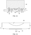
- FIG. 12 is a side view of an x-ray generation component attached to a gantry in accordance with an embodiment.
- FIG. 13 is a side view of an x-ray generation component with a port extension in accordance with an embodiment.
- FIG. 14 is a perspective view of a port extension of an x-ray generation component in accordance with an embodiment.
- FIG. 15 is a perspective view of a gantry section for receiving an x-ray generation component in accordance with an embodiment.
- FIG. 16 is a cross section view of a gantry section for receiving an x-ray generation component in accordance with an embodiment.
- FIG. 17 is a view of an in-use x-ray generation component attached to a gantry in accordance with an embodiment.
- FIG. 18 is a side view of an x-ray generation component being installed in a gantry in accordance with an embodiment.
- FIG. 19 a zoomed view of an x-ray generation component being installed in a gantry in accordance with an embodiment.
- FIG. 20 is a side view of an installed x-ray generation component after installation into a gantry in accordance with an embodiment.
- FIG. 21 is a perspective view of an installed x-ray generation component on a rotary member of a CT system gantry in accordance with an embodiment.
- FIG. 22 is a view of an installed x-ray generation component on an X-ray system gantry in accordance with an embodiment.
- FIGS. 1 and 2 show a computed tomography (CT) imaging system 10 including a gantry 12 .
- Gantry 12 has a rotary member 13 .
- An x-ray source 14 that projects a beam of x-rays 16 through pre-patient collimator 15 toward a detector assembly 18 on the opposite side of the rotary member 13 .
- X-ray source 14 may also be referred to as x-ray tube or x-ray generation component.
- X-ray source 14 is a type of emissions component.
- a main bearing may be utilized to attach the rotary member 13 to the stationary structure of the gantry 12 .
- Detector assembly 18 is formed by a plurality of detectors 20 and data acquisition systems (DAS) 22 , and can include a post-patient collimator.
- DAS data acquisition systems
- the plurality of detectors 20 sense the projected x-rays that pass through a subject 24 , and DAS 22 converts the data to digital signals for subsequent processing.
- Each detector 20 produces an analog or digital electrical signal that represents the intensity of an impinging beam of x-rays 16 and hence the attenuated beam as it passes through subject 24 .
- rotary member 13 and the components mounted thereon can rotate about a center of rotation.
- Control mechanism 26 can include an x-ray controller 28 and generator 30 that provides power and timing signals to x-ray source 14 and a gantry motor controller 32 that controls the rotational speed and position of rotary member 13 .
- An image reconstructor 34 receives sampled and digitized x-ray data from DAS 22 and performs high speed image reconstruction. The reconstructed image is output to a computer 36 which stores the image in a computer storage device 38 .
- Computer 36 also receives commands and scanning parameters from an operator via operator console 40 that has some form of operator interface, such as a keyboard, mouse, touch sensitive controller, voice activated controller, or any other suitable input apparatus.
- Display 42 allows the operator to observe the reconstructed image and other data from computer 36 .
- the operator supplied commands and parameters are used by computer 36 to provide control signals and information to DAS 22 , x-ray controller 28 , and gantry motor controller 32 .
- computer 36 operates a table motor controller 44 which controls a motorized table 46 to position subject 24 and gantry 12 .
- motorized table 46 moves a subject 24 through a gantry opening 48 , or bore, in whole or in part.
- a coordinate system 50 defines a patient or Z-axis 52 along which subject 24 is moved in and out of gantry opening 48 , a gantry circumferential or X-axis 54 along which detector assembly 18 passes, and a Y-axis 56 that passes along a direction from a focal spot of x-ray source 14 to detector assembly 18 .
- FIG. 3 shows one view of a rotary member 13 with a component 60 attached thereto, according to one embodiment.
- Rotary member 13 may also be referred to as a drum or disk.
- Component 60 can be an x-ray tube, high voltage generator, heat exchanger, collimator, image detector, circuit board chassis, balance weight, power supply, or other item to be attached to rotary member 13 .
- FIG. 3 shows primary attachment mechanism 62 and secondary attachment mechanism 64 in normal operation conditions.
- Primary attachment mechanism 62 may be bolts in one embodiment or other types of fastening elements in alternative embodiments.
- FIG. 3 shows the primary attachment mechanisms 62 attached to component 60 through slots 70 . While the primary attachment mechanisms 62 are shown at a perpendicular angle to the rotary member 13 , they can be set at alternative angles or orientations for fastening. In normal operation conditions as shown in FIG. 3 , primary attachment mechanism 62 is engaged, thus pressed flush against rotary member 13 , to prevent any pulling away of component 60 due to centrifugal, gravitational, or other forces during operation of the CT imaging system 10 . While FIG.
- FIG. 3 shows the sides of primary attachment mechanism 62 as not flush against rotary member 13 in slot 70 , the sides can be flush in alternative embodiments.
- Slot 70 may have threads to accept bolts or screws in one embodiment. While FIG. 3 shows two primary attachment mechanisms 62 , there can be any number in varying embodiments.
- Secondary attachment mechanism 64 is shown as a T-slot interface where component 60 has a T-slot fastener 68 that may be slid into T-slot socket 66 .
- T-slot fastener 68 includes a stem and a head.
- T-slot socket 66 is integrated into the rotary member 13 in this embodiment.
- T-slot socket 66 may be attached to rotary member 13 .
- T-slot fastener 68 is integrated into component 60 in this embodiment.
- T-slot fastener 68 may be attached to component 60 .
- Secondary attachment mechanism 64 is a safety device in one embodiment. In normal operation conditions shown in FIG. 3 , the secondary attachment mechanism 64 is not engaged and is bearing no component load, or weight. Thus, FIG.
- FIG. 3 shows no part of T-slot fastener 68 pressed flush against rotary member 13 . Not bearing load during normal operation keeps it as strong as possible and reduces wear. While FIG. 3 shows two secondary attachment mechanisms 64 , there can be any number in varying embodiments.
- a T-slot interface can be described in one embodiment as a socket having a base defining a recess bordered by a lip, and a fastener having an elongate stem portion and a head slidably insertable into the recess of the socket where it is retained by the lip of the socket.
- FIG. 4 shows a system where primary attachment mechanisms 62 are not installed and secondary attachment mechanisms 64 are engaged. Slots 70 in rotary member 13 are empty in this example. This could be in a situation where the primary attachment mechanisms 62 were never put into place, fell out, were not torqued enough for secure fastening, were not the right type of mechanism (wrong length, strength, etc.), are fatigued, are broken, or have had some other issue happen to them. This can be considered a failure condition of a primary attachment mechanism 62 . In this situation the secondary attachment mechanism 64 takes the load. This is shown by the head of T-slot fastener 68 being flush against the top part of T-slot socket 66 during rotation as the force pulls component 60 away from rotary member 13 .
- the secondary attachment mechanisms 64 protect component 60 from being ejected radially or otherwise from the rotary member 13 . There also could be a situation where secondary attachment mechanism 64 only takes part of the load, such as when only some of the primary attachment mechanisms 62 are engaged or the primary attachment mechanisms 62 used are weak for some reason.
- the gaps within the secondary attachment mechanism's T-slot interface allow for audible noise to be made when the secondary attachment mechanism 64 is engaged. This can alert a nearby human operator to notice that the gantry 12 is running in safety, or failsafe, mode and not in normal mode so the operator can attend to the safety issue.
- the system can be arranged so that the audible noises are only during gantry 12 spin-up and spin-down or all the time during operation.
- the gaps are such that no audible noise can be heard.
- the automatic engaging of the secondary attachment mechanism 64 is a failsafe. This can be desirable since a field engineer may not activate the failsafe if it is manual. A manual installed failsafe is subject to incorrect installation itself. According to some embodiments, the system can automatically engage and requires no manual intervention to activate the failsafe protection. Once the component 60 is in place, it will not be thrown from the rotating structure even without any primary attachment mechanisms 62 installed.
- FIG. 5 shows an engaged secondary attachment mechanism 64 .
- the design of the secondary attachment mechanism 64 results in substantially even force distribution since load is being carried by both sides of the T-shape according to one embodiment. This increases strength and reliability for the secondary attachment mechanism.
- FIG. 6 shows an angular view of rotary member 13 that includes one part of the secondary attachment mechanism 64 , the T-slot socket 66 .
- a component 60 is first slid in the Z-direction 52 into the rotary member 13 .
- primary attachment mechanisms 62 can be installed through slots 70 .
- the slot 70 arrangement shown in FIG. 6 is exemplary. There can be one or more slots 70 and set in various arrangements in rotary member 13 .
- FIG. 7 shows a view of secondary attachment mechanism 64 in an alternative embodiment.
- the T-slot fastener is integrated, or attached to, the rotary member 13 .
- the T-slot socket is integrated, or attached to, component 60 .
- FIGS. 8 and 9 show views of rotary member 13 that includes latch 72 .
- Latch 72 depresses as a component slides across it and into T-slot socket 66 .
- FIG. 8 shows an angled view.
- FIG. 9 shows a front view.
- a component with T-slot fastener could slide into rotary member 13 in the direction of the arrow shown in the T-slot sockets 66 in FIG. 8 .
- the latch 72 rises to secure the T slot fastener into place in the axial or Z-direction 52 .
- the latch 72 retains the component in the rotary member 13 T-slot socket 66 in the axial or Z-direction 52 .
- the latch 72 can also be referred to a Z-capture device, spring pin, or other names common to the art. It is a spring pin with a spring mechanism in one example embodiment.
- latch 72 is automatically engaged. It can be disengaged by manual user input or insertion of a component into the gantry's rotary member 13 . Latch 72 cannot be left in a disengaged condition in this embodiment. When a user input to the latch 72 is removed or the component is fully inserted, the latch 72 automatically returns to its engaged state. Latch 72 is further held in place when rotational forces push outward in the radial direction.
- FIG. 10 shows a side view of a component 60 inserted into rotary member 13 using the secondary attachment mechanism 64 according to one embodiment.
- the T-slot fastener head 74 has an angled edge 76 that depresses latch 72 as component 60 is slid into the secondary attachment mechanism 64 of rotary member 13 along the Z-direction 52 of the arrow in FIG. 10 . After component 60 is fully inserted, latch 72 automatically rises to block the removal of component 60 without manual input. Angled edge 76 can also be known as a chamfer or ramp.
- FIG. 11 shows additional embodiments of the system.
- Rotary member 13 has thus far been shown with components 60 on the outside of the rotary member 13 .
- FIG. 11 shows components 60 , of various shapes and sizes, attached or mounted to the inside of rotary member 13 .
- Primary attachment mechanisms 62 are still part of the system, but are not shown in the drawing.
- Secondary attachment mechanisms 64 are shown, sometimes with one, two, or three per component 60 to show the flexibility of the system.
- components can be placed on both the inside and outside of rotary member 13 .
- Both forms of attachment mechanisms help the component 60 stay centered and attached to the respective support structure.
- the support structure may be a rotary member 13 as discussed above as well as a stationary structure as in a diagnostic x-ray system or baggage scanning system. If the component 60 stays attached and centered, the interfaces between the component 60 and the remaining parts of the system remain aligned and are more likely to function as planned.
- FIG. 12 is a side view of an x-ray generation component attached to a gantry in accordance with an embodiment.
- component 102 which may be an x-ray tube in an embodiment.
- Component 102 comprises a port extension 100 .
- Port extension 100 protrudes into a recess in rotary member 13 in the embodiment of FIG. 12 , but can extend into a recess of other support structures in alternate embodiments.
- FIG. 12 shows an integrated interface.
- FIG. 12 shows that port extension 100 does not physically contact rotary member 13 .
- FIG. 12 shows that port extension 100 can have rounded edges.
- port extension 100 has right angle edges.
- port extension 100 has slanted chamfer edges.
- FIG. 12 shows an overlapping design providing overlapping x-ray shielding against scatter radiation, as is discussed further below.
- the port extension 100 is attached to or within the component 102 , and the recess is attached to or within the rotary member 13 .
- the port extension 100 is attached to or within a support structure and the recess is attached to or within the component 102 .
- FIG. 13 is a side view of an x-ray generation component with a port extension 104 in accordance with an embodiment.
- Component 102 is shown with a port extension 104 .
- Port extension 104 has chamfered edges in the embodiment of FIG. 13 . The chamfer rises inward around the end of the port extension 104 .
- Port extension 104 protrudes from the lower surface of component 102 in the direction of the emission of x-rays 106 .
- X-rays 106 are being emitted out of the component 102 which is an x-ray tube.
- Port extension 104 frames an opening from the x-ray tube component 102 to allow x-rays 106 to emit from the x-ray tube component 102 .
- X-rays 106 may also be referred to as the imaging beam.
- FIG. 14 is a perspective view of a port extension 104 of an x-ray generation component in accordance with an embodiment.
- Port extension 104 is shown as protruding outwards from the surface of component 102 .
- Port extension 104 frames the port opening 108 that allows unattenuated x-rays to be transmitted from the x-ray generation component 102 .
- Port opening 108 is shown as oval in FIG. 14 , but may be other shapes such as a ring, rectangle, octagon, or other shapes as is reasonable for the application.
- FIG. 15 is an isometric perspective view of a gantry section for receiving an x-ray generation component in accordance with an embodiment.
- FIG. 15 shows base 110 , recess 114 , and base opening 118 .
- Base 110 maybe within or attached to a support structure such as rotary member 13 , a pre-patient collimator, or a stationary support structure, such as for medical scanning or baggage scanning. If base 110 is a separate piece attached to such structures in certain embodiments, it may be called a top cap.
- Base 110 comprises a recess 114 , also called a recessed pocket as it can be a machined pocket.
- Recess 114 surrounds the component port extension. Recess 114 has a shielded edge, shown further in FIG. 16 .
- Recess 114 comprises base opening 118 .
- Base opening 118 allows for the unattenuated, or substantially unattenuated, passage of x-rays or other imaging beams.
- Base opening 118 is shown as oval in FIG. 15 , but may be other shapes such as a ring, rectangle, octagon, or other shapes as is reasonable for the application.
- FIG. 16 is a cross section view of a gantry section for receiving an x-ray generation component in accordance with an embodiment.
- FIG. 16 is a section view including base 110 , recess 114 , and shielded recess edge 116 . Shielding within the edge blocks the flow of x-ray radiation in the direction of the recess edge 116 .
- FIG. 17 is a view of an in-use x-ray generation component attached to a gantry in accordance with an embodiment.
- Component 102 comprises a port extension 104 that is either attached to or embedded within component 102 .
- Base 110 comprises a recess 114 for receiving port extension 104 .
- the tube port extension 104 protrudes into recess 114 in the gantry to provide a physically overlapping design to the interface.
- X-rays 106 emit from x-ray generation component 102 , through the opening of port extension 104 , and through the opening of base 110 to be transmitted through an object to be imaged.
- port extension 104 has shielding around the frame of its opening, and recess 114 has a shielded recess edge 116 .
- This double shielding approach can be called an overlapped approach, nested approach, or labyrinth approach.
- Port extension 104 protrudes into recess 114 such that the frame of port extension 104 provides a primary shielding effect upon scatter x-ray radiation and the frame of the recess provides a secondary shielding effect upon scatter x-ray radiation.
- the overlapping design ensures that there is no line of sight for scattered x-rays to escape without passing through shielding. Any scattered x-rays that impinge on the gantry tube interface structure, recess walls, or port extension are attenuated.
- the level of attenuation depends on the material selection, physical overlap, and part thicknesses.
- steel is used for port extension 104 and recess 114 .
- Other materials can be used such as lead, injection molded tungsten plastic, or other materials with high x-ray attenuation rates.
- This approach helps for large coverage tubes. This approach allows for lower dose and the control of unwanted leakage radiation, radiation that is not actually used for imaging. This unwanted radiation could enter the patient, operator, or others in the area that are not supposed to be affected by the radiation. Thus, preventing unwanted radiation is a benefit for health and safety.
- FIG. 18 is a side view of an x-ray generation component being installed in a gantry in accordance with an embodiment.
- FIG. 19 a zoomed view of an x-ray generation component being installed in a gantry in accordance with an embodiment.
- the x-ray generation component is slidably inserted into the support structured and then it lowers into place once the port extension and recess are aligned, in such a way that contact between the port extension and the support structure is not made.
- FIG. 18 and FIG. 19 will be discussed together as they detail the mid-installation view of the system, interface, apparatus, and method.
- FIGS. 18 and 19 shows x-ray generation component 102 being installed, in the installation direction 121 , onto base 110 .
- Component 102 comprises a protruding port extension 104 that is not in contact with base 110 during, or after, installation. This is made possible during installation by base button 120 holding up component 102 as it slides into the base on the left side of FIG. 18 .
- Base button 120 extends outward from the base at a height that is larger than the depth of recess 114 .
- the non-contact is also made possible by component pin 122 that holds the other side of component 102 aloft to prevent contact of the port extension 104 from the base 110 or its recess 114 .
- Component pin 122 extends outward from the component in the same direction as the port extension 104 , wherein the height of the pin is larger than the height of the port extension 104 , as shown further in FIG. 20 .
- Base button 120 may also be called a gantry button or protruding feature.
- Component pin 122 may also be called a tube pin, protruding feature, or dowel pin.
- Base button 120 and Component pin 122 work together to keep component 102 aloft during installation and removal. The slide and lower installation method works well with the secondary attachment mechanism such as a t-slot as mentioned above with reference to FIG. 10 , for example.
- component pin 122 When port extension 104 is correctly aligned with recess 114 , component pin 122 will be correctly aligned with base pin slot 124 and component 102 will have no remaining portion above base button 120 . This allows component 102 to lower onto base 110 only when correctly aligned such that port extension 104 does not come in contact with any portion of base 110 or recess 114 . When installed, shown further in FIG. 20 , port extension 104 is fully within, but not in contact with, recess 114 . Component pin 122 is the same, or substantially the same, height as base button 120 , as far as the heights they extend outward from the surface of the component and base, respectfully. Note that the button and pin are currently installed on different structures in an embodiment. In alternate embodiments, the button and pin could be on the same structure, either the x-ray component or the support structure.
- port extension 104 cannot remain error free, avoid misuse, and avoid damage.
- the installation and removal of component 102 into base 110 does not allow for such contact.
- the installation or removal can be protected against damage using these physical design features.
- the integrity of the shielding seal of the interface is maintained and scatter radiation is kept lower. Further, this prevents part damage or infiltration of foreign material (metal, dust, and etcetera) into the pre-patient collimator or other attached components.
- the field engineer or operator perform the needed operation without these parts coming into contact and becoming damaged with handling.
- the potential for imaging artifacts is reduced by this design. Metal particles that find their way into the pre-patient collimator can get into the image chain and cause imaging artifacts. Because of the non-contact radiation shielding, there is no way to generate metal particles from rubbing parts in the vicinity of the gantry recess area. Any parts that rub in this area risk putting metal particles into the pre-patient collimator; the gantry recess area may be open to the pre-patient collimator. The contact between the component and base in other areas (pin 122 and pin slot 124 ; button 120 and component 102 ) is sufficiently far from the gantry recess area that particles will not fall into the pre-patient collimator.
- FIG. 20 is a side view of an installed x-ray generation component after installation into a gantry in accordance with an embodiment. Installation is now complete.
- Component 102 is attached to base 110 through primary and/or secondary attachment mechanisms, as discussed above. None of component 102 is resting on base button 120 .
- Component pin 122 is lowered and within base pin slot 124 .
- Port extension 104 is lowered and within, but not in contact with, recess 114 .
- port extension 104 protrudes into gantry recess 114 .
- Base button height 132 and component pin protrusion height 130 are both larger than the amount of protrusion of port extension 104 . Thus, contact is controlled for the component 102 and prevented for protruding port extension 104 .
- Port extension shielding 112 around the frame of the port extension opening is a first prevention of scatter x-ray radiation.
- Recess shielding 113 is a second, overlapping, prevention of scatter x-ray radiation. Dual shielding is thus achieved for scatter radiation.
- FIG. 20 shows a self-protecting x-ray tube and gantry interface for integrated x-ray scatter shielding.
- FIG. 21 is a perspective view of an installed x-ray generation component on a rotary member of a CT system gantry in accordance with an embodiment.
- interfaces in varying embodiments may also be applied to other types of radiation generating equipment such as fixed or mobile radiographic systems.
- FIG. 22 is a view of an installed x-ray generation component on an X-ray system gantry in accordance with an embodiment.
- the port extension and recess interface between x-ray tube and its support structure, such as the pre-patient collimator 216 in this embodiment, can be implemented in such an embodiment.
- FIG. 22 illustrates an exemplary diagnostic imaging system 210 configured to continuously image the internal features of a subject, such as anatomy of a human subject or patient 212 in a medical or screening context, throughout an imaging operation.
- the illustrated diagnostic imaging system 210 includes an X-ray tube 214 with a collimator 216 , a port 217 , and filters (not shown), a table 218 on which the patient is positioned, an imaging console 220 , an image intensifier 222 , a camera 224 , and a monitor 226 .
- the imaging console 220 includes a user interface 228 including a first control panel 230 and a second control panel 232 .
- the first control panel 230 includes a display 234 and a plurality of configurable adjustments 236 .
- the second control panel 232 includes a display 238 and a plurality of configurable adjustments 240 and 242 , which are configured to increase or decrease a parameter value, respectively.
- the monitor 226 also includes a display 224 configured to display a sequence of images to an operator during the imaging operation.
- the X-ray source 214 generates an X-ray beam, for example, via a conventional cathode and anode X-ray production system.
- the X-ray beam may be filtered to provide the desired energy spectrum before reaching the pre-patient collimator 216 .
- some embodiments may include one or more desired filters such as energy based filters (e.g., aluminum), equalization filters (e.g., trough filters, bow-tie filters, wedge filters, etc.), and so forth.
- the size and shape of the X-ray beam is adjusted by the pre-patient collimator 216 before emerging from the port 217 .
- the x-ray source 214 may have a port extension, and the pre-patient collimator 216 may have a recess to receive the x-ray source port extension, as discussed further above.
- the X-ray beam is attenuated by the patient's anatomy, and at least a portion of the attenuated beam is detected by a high sensitive detector of the image intensifier 222 mounted to the imaging console 220 .
- the image intensifier 222 is adapted to produce a projection image of an acceptable quality from a low number of X-ray photons. Such a feature may be advantageous in fluoroscopy systems since continuous imaging throughout the imaging operation may expose the patient to substantial quantities of X-ray energy.
- the output signals from the image intensifier 222 are continuously transferred via the video camera 224 to the monitor 226 for viewing on the display 244 during the imaging operation.
- the system may be used in different contexts as well.
- the system may be used for screening and similar applications.
- the system may be used for detection of items in parcels, luggage, transport vehicles, and so forth.
- such x-ray imaging systems may be utilized for inspection of industrial parts, such as pipes or wind blades.
- the system disclosed provides beneficial safety features, maintenance features, image quality improvements, and interface mechanisms.
- Installers have an easy to implement installation structure. Patients and operators have less dose to worry about. Radiologist have higher quality images with less artifacts. And the hardware itself may last longer and need less maintenance.
Landscapes
- Health & Medical Sciences (AREA)
- Life Sciences & Earth Sciences (AREA)
- Engineering & Computer Science (AREA)
- Medical Informatics (AREA)
- Physics & Mathematics (AREA)
- Heart & Thoracic Surgery (AREA)
- Surgery (AREA)
- Nuclear Medicine, Radiotherapy & Molecular Imaging (AREA)
- Optics & Photonics (AREA)
- Pathology (AREA)
- Radiology & Medical Imaging (AREA)
- Biomedical Technology (AREA)
- Biophysics (AREA)
- Molecular Biology (AREA)
- High Energy & Nuclear Physics (AREA)
- Animal Behavior & Ethology (AREA)
- General Health & Medical Sciences (AREA)
- Public Health (AREA)
- Veterinary Medicine (AREA)
- Pulmonology (AREA)
- Theoretical Computer Science (AREA)
- Mathematical Physics (AREA)
- Apparatus For Radiation Diagnosis (AREA)
- Computer Vision & Pattern Recognition (AREA)
- Human Computer Interaction (AREA)
Abstract
Description
Claims (20)
Priority Applications (2)
| Application Number | Priority Date | Filing Date | Title |
|---|---|---|---|
| US15/153,989 US10791999B2 (en) | 2014-02-04 | 2016-05-13 | Interface for gantry and component |
| CN201710342111.4A CN107361779B (en) | 2016-05-13 | 2017-05-12 | Interface for gantry and component |
Applications Claiming Priority (3)
| Application Number | Priority Date | Filing Date | Title |
|---|---|---|---|
| US14/171,892 US9204850B2 (en) | 2014-02-04 | 2014-02-04 | Gantry with secondary safety mechanism |
| US14/930,275 US10219760B2 (en) | 2014-02-04 | 2015-11-02 | Rotary member with safety mechanism |
| US15/153,989 US10791999B2 (en) | 2014-02-04 | 2016-05-13 | Interface for gantry and component |
Related Parent Applications (1)
| Application Number | Title | Priority Date | Filing Date |
|---|---|---|---|
| US14/930,275 Continuation-In-Part US10219760B2 (en) | 2014-02-04 | 2015-11-02 | Rotary member with safety mechanism |
Publications (2)
| Publication Number | Publication Date |
|---|---|
| US20160249871A1 US20160249871A1 (en) | 2016-09-01 |
| US10791999B2 true US10791999B2 (en) | 2020-10-06 |
Family
ID=56798583
Family Applications (1)
| Application Number | Title | Priority Date | Filing Date |
|---|---|---|---|
| US15/153,989 Active 2035-07-21 US10791999B2 (en) | 2014-02-04 | 2016-05-13 | Interface for gantry and component |
Country Status (1)
| Country | Link |
|---|---|
| US (1) | US10791999B2 (en) |
Cited By (1)
| Publication number | Priority date | Publication date | Assignee | Title |
|---|---|---|---|---|
| US11166685B2 (en) * | 2018-08-03 | 2021-11-09 | Canon Medical Systems Corporation | Radiation detector and radiation detector module |
Citations (65)
| Publication number | Priority date | Publication date | Assignee | Title |
|---|---|---|---|---|
| US4893321A (en) * | 1986-11-21 | 1990-01-09 | Siemens Aktiengesellschaft | X-radiator, particularly for producing intra-oral dental exposures |
| US4905268A (en) * | 1985-10-25 | 1990-02-27 | Picker International, Inc. | Adjustable off-focal aperture for x-ray tubes |
| US5479021A (en) * | 1991-06-10 | 1995-12-26 | Picker International, Inc. | Transmission line source assembly for spect cameras |
| US5487098A (en) * | 1994-02-03 | 1996-01-23 | Analogic Corporation | Modular detector arrangement for X-ray tomographic system |
| US5636259A (en) * | 1995-05-18 | 1997-06-03 | Continental X-Ray Corporation | Universal radiographic/fluoroscopic digital room |
| US5703921A (en) * | 1995-05-30 | 1997-12-30 | Kabushiki Kaisha Toshiba | X-ray computed tomography apparatus |
| US5834780A (en) * | 1996-05-29 | 1998-11-10 | Picker International, Inc. | Scanning line source for gamma camera |
| US5991357A (en) * | 1997-12-16 | 1999-11-23 | Analogic Corporation | Integrated radiation detecting and collimating assembly for X-ray tomography system |
| US6314157B1 (en) * | 1998-10-16 | 2001-11-06 | Kabushiki Kaisha Toshiba | Arrangements for mounting units in a computed tomography system |
| US6519312B1 (en) * | 2000-08-16 | 2003-02-11 | Analogic Corporation | System and method for mounting x-ray tube in CT scanner |
| US6587538B2 (en) * | 2000-11-27 | 2003-07-01 | Kabushiki Kaisha Toshiba | Detector unit, X-ray computer tomographic photographing device, X-ray detector, and X-ray detector manufacturing method |
| US6590953B2 (en) * | 2000-09-12 | 2003-07-08 | Hitachi Medical Corporation | X-ray CT scanner |
| US6810103B1 (en) * | 2001-07-16 | 2004-10-26 | Analogic Corporation | Gantry for combined tomography scanner |
| US6890100B2 (en) * | 2003-07-18 | 2005-05-10 | Ge Medical Systems Global Technology, Inc. | CT gantry balance system |
| US6917664B2 (en) * | 2002-10-03 | 2005-07-12 | Koninklijke Philips Electronics N.V. | Symmetrical multiple-slice computed tomography data management system |
| US7015476B2 (en) * | 1999-04-14 | 2006-03-21 | Juni Jack E | Single photon emission computed tomography system |
| US7029176B2 (en) * | 2003-09-12 | 2006-04-18 | Instrumentarium Corp. | X-ray apparatus for intraoral imaging applications |
| US7076018B2 (en) * | 2004-07-23 | 2006-07-11 | Siemens Aktiengesellschaft | Tomography apparatus with gantry-carried component mounted to withstand centrifugal forces |
| US7105825B2 (en) * | 1999-04-14 | 2006-09-12 | Juni Jack E | Single photon emission computed tomography system |
| US7108421B2 (en) * | 2002-03-19 | 2006-09-19 | Breakaway Imaging, Llc | Systems and methods for imaging large field-of-view objects |
| US7190759B2 (en) * | 2002-12-19 | 2007-03-13 | General Electric Company | Support structure for Z-extensible CT detectors and methods of making same |
| US7235788B2 (en) * | 2003-11-21 | 2007-06-26 | Siemens Aktiengesellschaft | Detector for a tomography unit |
| US7257195B2 (en) * | 2003-12-23 | 2007-08-14 | Siemens Aktiengesellschaft | Collimator for a computer tomograph |
| US7281848B2 (en) * | 2005-08-17 | 2007-10-16 | General Electric Co. | X-ray tube mounting methodology |
| US7290929B2 (en) * | 2004-02-09 | 2007-11-06 | Varian Medical Systems Technologies, Inc. | Mounting system for an X-ray tube |
| US7396160B2 (en) * | 2004-07-30 | 2008-07-08 | Neurologica Corp. | Computerized tomography (CT) imaging system with monoblock X-ray tube assembly |
| US7465931B2 (en) * | 2003-11-28 | 2008-12-16 | Koninklijke Philips Electronics N.V. | Radiation detector module |
| US7489516B2 (en) * | 2004-11-24 | 2009-02-10 | General Electric Company | Digital CT detector module methods and apparatus |
| US7519157B2 (en) * | 2005-07-23 | 2009-04-14 | General Electric Company | Systems, methods and apparatus for attachment of an X-ray tube to an X-ray tube collimator frame |
| US7525097B2 (en) * | 2004-04-06 | 2009-04-28 | Koninklijke Philips Electronics N.V. | Modular device for the detection and/or transmission of radiation with self-aligning modules |
| US7564940B2 (en) * | 2003-07-22 | 2009-07-21 | Koninklijke Philips Electronics N.V. | Radiation mask for two dimensional CT detector |
| US7606346B2 (en) * | 2007-01-04 | 2009-10-20 | General Electric Company | CT detector module construction |
| US7783000B2 (en) * | 2005-04-22 | 2010-08-24 | Hamamatsu Photonics K.K. | Photodetection unit, photodetector, and x-ray computed tomography apparatus |
| US7927013B2 (en) * | 2008-08-01 | 2011-04-19 | Siemens Aktiengesellschaft | Computed tomography rotor, and gantry embodying same |
| US7942576B2 (en) * | 2008-06-12 | 2011-05-17 | Tsinghua University | Adjusting positioner for radiation device |
| US8290119B2 (en) * | 2007-01-24 | 2012-10-16 | Imaging Sciences International Llc | Adjustable scanner |
| US8306182B2 (en) * | 2009-03-06 | 2012-11-06 | Kabushiki Kaisha Toshiba | X-ray CT apparatus and X-ray detecting apparatus thereof |
| US8462911B2 (en) * | 2007-11-06 | 2013-06-11 | Koninklijke Philips Electronics N.V. | Nuclear medicine SPECT-CT machine with integrated asymmetric flat panel cone-beam CT and SPECT system |
| US8483352B2 (en) * | 2006-09-19 | 2013-07-09 | General Electric Company | Stacked x-ray detector assembly and method of making same |
| US8483362B2 (en) * | 2009-12-02 | 2013-07-09 | Siemens Aktiengesellschaft | Collimator module for the modular assembly of a collimator for a radiation detector and radiation detector |
| US8488736B2 (en) * | 2006-09-19 | 2013-07-16 | General Electric Company | Stacked flat panel x-ray detector assembly and method of making same |
| US8681930B2 (en) * | 2007-11-16 | 2014-03-25 | Koninklijke Philips N.V. | High speed rotating gantry |
| US8693621B2 (en) * | 2008-05-01 | 2014-04-08 | Koninklijke Philips N. V. | Source and/or detector positioning system |
| US8768032B2 (en) * | 2012-07-06 | 2014-07-01 | Morpho Detection, Llc | Method for correction of artifacts from edge detectors in compact geometry CT |
| US8781061B2 (en) * | 2009-04-16 | 2014-07-15 | Hitachi Medical Corporation | X-ray CT rotary apparatus |
| US8890079B2 (en) * | 2012-06-29 | 2014-11-18 | General Electric Company | Radiation detection device and radiation tomographic apparatus, and method for assembling radiation detection device |
| US8987675B2 (en) * | 2012-08-28 | 2015-03-24 | Ge Medical Systems Global Technology Company, Llc | Radiation detecting apparatus and radiation imaging apparatus |
| US9044151B2 (en) * | 2013-06-12 | 2015-06-02 | General Electric Company | Straddle mount detector assembly |
| US9044152B2 (en) * | 2012-04-05 | 2015-06-02 | Analogic Corporation | Rotatable drum assembly for radiology imaging modalities |
| US9125613B2 (en) * | 2012-06-12 | 2015-09-08 | Mobius Imaging, Llc | Detector system for imaging device |
| US9198631B2 (en) * | 2012-09-04 | 2015-12-01 | Rigaku Corporation | X-ray CT apparatus |
| US9200948B2 (en) * | 2013-10-28 | 2015-12-01 | Institute Of Nuclear Energy Research, Atomic Energy Council, Executive Yuan | Tomographic scanning apparatus |
| US9208918B2 (en) * | 2012-11-16 | 2015-12-08 | Neurologica Corp. | Computerized tomography (CT) imaging system with multi-slit rotatable collimator |
| US9204850B2 (en) * | 2014-02-04 | 2015-12-08 | General Electric Company | Gantry with secondary safety mechanism |
| US9332945B2 (en) * | 2012-02-22 | 2016-05-10 | Kabushiki Kaisha Toshiba | X-ray CT system |
| US9414793B2 (en) * | 2012-02-22 | 2016-08-16 | Toshiba Medical Systems Corporation | X-ray CT system |
| US9480440B2 (en) * | 2011-09-28 | 2016-11-01 | Qr Srl | System and method for cone beam computed tomography |
| US9526461B2 (en) * | 2012-06-26 | 2016-12-27 | Mobius Imaging, Llc | Multi-plane x-ray imaging system and method |
| US9668330B2 (en) * | 2011-08-26 | 2017-05-30 | Toshiba Medical Systems Corporation | Gantry of X-ray CT system |
| US9737273B2 (en) * | 2011-04-07 | 2017-08-22 | Mobius Imaging, Llc | Mobile X-ray imaging system |
| US9820707B2 (en) * | 2014-02-05 | 2017-11-21 | Siemens Aktiengesellschaft | X-ray device |
| US9848837B2 (en) * | 2013-05-06 | 2017-12-26 | Koninklijke Philips N.V. | Imaging system rotating component alignment with iso-center |
| US9888886B2 (en) * | 2013-10-18 | 2018-02-13 | Siemens Aktiengesellschaft | Rotor with a backplane bus having electrical connection elements to make electrical contact with electrical components in a medical apparatus, as well as rotating unit and medical apparatus with such a rotor |
| US9924915B2 (en) * | 2012-02-22 | 2018-03-27 | Toshiba Medical Systems Corporation | X-ray CT apparatus |
| US10022095B2 (en) * | 2015-11-17 | 2018-07-17 | General Electric Company | Support structure with raisable cover |
-
2016
- 2016-05-13 US US15/153,989 patent/US10791999B2/en active Active
Patent Citations (67)
| Publication number | Priority date | Publication date | Assignee | Title |
|---|---|---|---|---|
| US4905268A (en) * | 1985-10-25 | 1990-02-27 | Picker International, Inc. | Adjustable off-focal aperture for x-ray tubes |
| US4893321A (en) * | 1986-11-21 | 1990-01-09 | Siemens Aktiengesellschaft | X-radiator, particularly for producing intra-oral dental exposures |
| US5479021A (en) * | 1991-06-10 | 1995-12-26 | Picker International, Inc. | Transmission line source assembly for spect cameras |
| US5487098A (en) * | 1994-02-03 | 1996-01-23 | Analogic Corporation | Modular detector arrangement for X-ray tomographic system |
| US5636259A (en) * | 1995-05-18 | 1997-06-03 | Continental X-Ray Corporation | Universal radiographic/fluoroscopic digital room |
| US5703921A (en) * | 1995-05-30 | 1997-12-30 | Kabushiki Kaisha Toshiba | X-ray computed tomography apparatus |
| US6060712A (en) * | 1996-05-29 | 2000-05-09 | Picker International, Inc. | Scanning line source for gamma camera |
| US5834780A (en) * | 1996-05-29 | 1998-11-10 | Picker International, Inc. | Scanning line source for gamma camera |
| US5991357A (en) * | 1997-12-16 | 1999-11-23 | Analogic Corporation | Integrated radiation detecting and collimating assembly for X-ray tomography system |
| US6314157B1 (en) * | 1998-10-16 | 2001-11-06 | Kabushiki Kaisha Toshiba | Arrangements for mounting units in a computed tomography system |
| US7105825B2 (en) * | 1999-04-14 | 2006-09-12 | Juni Jack E | Single photon emission computed tomography system |
| US7015476B2 (en) * | 1999-04-14 | 2006-03-21 | Juni Jack E | Single photon emission computed tomography system |
| US6519312B1 (en) * | 2000-08-16 | 2003-02-11 | Analogic Corporation | System and method for mounting x-ray tube in CT scanner |
| US6590953B2 (en) * | 2000-09-12 | 2003-07-08 | Hitachi Medical Corporation | X-ray CT scanner |
| US6587538B2 (en) * | 2000-11-27 | 2003-07-01 | Kabushiki Kaisha Toshiba | Detector unit, X-ray computer tomographic photographing device, X-ray detector, and X-ray detector manufacturing method |
| US6810103B1 (en) * | 2001-07-16 | 2004-10-26 | Analogic Corporation | Gantry for combined tomography scanner |
| US7108421B2 (en) * | 2002-03-19 | 2006-09-19 | Breakaway Imaging, Llc | Systems and methods for imaging large field-of-view objects |
| US6917664B2 (en) * | 2002-10-03 | 2005-07-12 | Koninklijke Philips Electronics N.V. | Symmetrical multiple-slice computed tomography data management system |
| US7190759B2 (en) * | 2002-12-19 | 2007-03-13 | General Electric Company | Support structure for Z-extensible CT detectors and methods of making same |
| US6890100B2 (en) * | 2003-07-18 | 2005-05-10 | Ge Medical Systems Global Technology, Inc. | CT gantry balance system |
| US7564940B2 (en) * | 2003-07-22 | 2009-07-21 | Koninklijke Philips Electronics N.V. | Radiation mask for two dimensional CT detector |
| US7029176B2 (en) * | 2003-09-12 | 2006-04-18 | Instrumentarium Corp. | X-ray apparatus for intraoral imaging applications |
| US7235788B2 (en) * | 2003-11-21 | 2007-06-26 | Siemens Aktiengesellschaft | Detector for a tomography unit |
| US7465931B2 (en) * | 2003-11-28 | 2008-12-16 | Koninklijke Philips Electronics N.V. | Radiation detector module |
| US7257195B2 (en) * | 2003-12-23 | 2007-08-14 | Siemens Aktiengesellschaft | Collimator for a computer tomograph |
| US7290929B2 (en) * | 2004-02-09 | 2007-11-06 | Varian Medical Systems Technologies, Inc. | Mounting system for an X-ray tube |
| US7525097B2 (en) * | 2004-04-06 | 2009-04-28 | Koninklijke Philips Electronics N.V. | Modular device for the detection and/or transmission of radiation with self-aligning modules |
| US7076018B2 (en) * | 2004-07-23 | 2006-07-11 | Siemens Aktiengesellschaft | Tomography apparatus with gantry-carried component mounted to withstand centrifugal forces |
| US7396160B2 (en) * | 2004-07-30 | 2008-07-08 | Neurologica Corp. | Computerized tomography (CT) imaging system with monoblock X-ray tube assembly |
| US7489516B2 (en) * | 2004-11-24 | 2009-02-10 | General Electric Company | Digital CT detector module methods and apparatus |
| US7783000B2 (en) * | 2005-04-22 | 2010-08-24 | Hamamatsu Photonics K.K. | Photodetection unit, photodetector, and x-ray computed tomography apparatus |
| US7519157B2 (en) * | 2005-07-23 | 2009-04-14 | General Electric Company | Systems, methods and apparatus for attachment of an X-ray tube to an X-ray tube collimator frame |
| US7281848B2 (en) * | 2005-08-17 | 2007-10-16 | General Electric Co. | X-ray tube mounting methodology |
| US8483352B2 (en) * | 2006-09-19 | 2013-07-09 | General Electric Company | Stacked x-ray detector assembly and method of making same |
| US8488736B2 (en) * | 2006-09-19 | 2013-07-16 | General Electric Company | Stacked flat panel x-ray detector assembly and method of making same |
| US7606346B2 (en) * | 2007-01-04 | 2009-10-20 | General Electric Company | CT detector module construction |
| US8290119B2 (en) * | 2007-01-24 | 2012-10-16 | Imaging Sciences International Llc | Adjustable scanner |
| US8462911B2 (en) * | 2007-11-06 | 2013-06-11 | Koninklijke Philips Electronics N.V. | Nuclear medicine SPECT-CT machine with integrated asymmetric flat panel cone-beam CT and SPECT system |
| US8681930B2 (en) * | 2007-11-16 | 2014-03-25 | Koninklijke Philips N.V. | High speed rotating gantry |
| US8693621B2 (en) * | 2008-05-01 | 2014-04-08 | Koninklijke Philips N. V. | Source and/or detector positioning system |
| US7942576B2 (en) * | 2008-06-12 | 2011-05-17 | Tsinghua University | Adjusting positioner for radiation device |
| US7927013B2 (en) * | 2008-08-01 | 2011-04-19 | Siemens Aktiengesellschaft | Computed tomography rotor, and gantry embodying same |
| US8306182B2 (en) * | 2009-03-06 | 2012-11-06 | Kabushiki Kaisha Toshiba | X-ray CT apparatus and X-ray detecting apparatus thereof |
| US8781061B2 (en) * | 2009-04-16 | 2014-07-15 | Hitachi Medical Corporation | X-ray CT rotary apparatus |
| US8483362B2 (en) * | 2009-12-02 | 2013-07-09 | Siemens Aktiengesellschaft | Collimator module for the modular assembly of a collimator for a radiation detector and radiation detector |
| US9737273B2 (en) * | 2011-04-07 | 2017-08-22 | Mobius Imaging, Llc | Mobile X-ray imaging system |
| US9668330B2 (en) * | 2011-08-26 | 2017-05-30 | Toshiba Medical Systems Corporation | Gantry of X-ray CT system |
| US9480440B2 (en) * | 2011-09-28 | 2016-11-01 | Qr Srl | System and method for cone beam computed tomography |
| US9924915B2 (en) * | 2012-02-22 | 2018-03-27 | Toshiba Medical Systems Corporation | X-ray CT apparatus |
| US9332945B2 (en) * | 2012-02-22 | 2016-05-10 | Kabushiki Kaisha Toshiba | X-ray CT system |
| US9414793B2 (en) * | 2012-02-22 | 2016-08-16 | Toshiba Medical Systems Corporation | X-ray CT system |
| US9044152B2 (en) * | 2012-04-05 | 2015-06-02 | Analogic Corporation | Rotatable drum assembly for radiology imaging modalities |
| US9125613B2 (en) * | 2012-06-12 | 2015-09-08 | Mobius Imaging, Llc | Detector system for imaging device |
| US9526461B2 (en) * | 2012-06-26 | 2016-12-27 | Mobius Imaging, Llc | Multi-plane x-ray imaging system and method |
| US8890079B2 (en) * | 2012-06-29 | 2014-11-18 | General Electric Company | Radiation detection device and radiation tomographic apparatus, and method for assembling radiation detection device |
| US8768032B2 (en) * | 2012-07-06 | 2014-07-01 | Morpho Detection, Llc | Method for correction of artifacts from edge detectors in compact geometry CT |
| US8987675B2 (en) * | 2012-08-28 | 2015-03-24 | Ge Medical Systems Global Technology Company, Llc | Radiation detecting apparatus and radiation imaging apparatus |
| US9198631B2 (en) * | 2012-09-04 | 2015-12-01 | Rigaku Corporation | X-ray CT apparatus |
| US9208918B2 (en) * | 2012-11-16 | 2015-12-08 | Neurologica Corp. | Computerized tomography (CT) imaging system with multi-slit rotatable collimator |
| US9848837B2 (en) * | 2013-05-06 | 2017-12-26 | Koninklijke Philips N.V. | Imaging system rotating component alignment with iso-center |
| US9044151B2 (en) * | 2013-06-12 | 2015-06-02 | General Electric Company | Straddle mount detector assembly |
| US9888886B2 (en) * | 2013-10-18 | 2018-02-13 | Siemens Aktiengesellschaft | Rotor with a backplane bus having electrical connection elements to make electrical contact with electrical components in a medical apparatus, as well as rotating unit and medical apparatus with such a rotor |
| US9200948B2 (en) * | 2013-10-28 | 2015-12-01 | Institute Of Nuclear Energy Research, Atomic Energy Council, Executive Yuan | Tomographic scanning apparatus |
| US9204850B2 (en) * | 2014-02-04 | 2015-12-08 | General Electric Company | Gantry with secondary safety mechanism |
| US10219760B2 (en) * | 2014-02-04 | 2019-03-05 | General Electric Company | Rotary member with safety mechanism |
| US9820707B2 (en) * | 2014-02-05 | 2017-11-21 | Siemens Aktiengesellschaft | X-ray device |
| US10022095B2 (en) * | 2015-11-17 | 2018-07-17 | General Electric Company | Support structure with raisable cover |
Non-Patent Citations (1)
| Title |
|---|
| Authors et. al.: Disclosed Anonymously, "Nested Shielding for Blocking Scattered Xrays", An IP.com prior Art Database Technical Disclosure, IP.com No. IPCOM000199836D, IP.com Electronic Publication Date: Sep. 17, 2010; 6 pages. |
Cited By (1)
| Publication number | Priority date | Publication date | Assignee | Title |
|---|---|---|---|---|
| US11166685B2 (en) * | 2018-08-03 | 2021-11-09 | Canon Medical Systems Corporation | Radiation detector and radiation detector module |
Also Published As
| Publication number | Publication date |
|---|---|
| US20160249871A1 (en) | 2016-09-01 |
Similar Documents
| Publication | Publication Date | Title |
|---|---|---|
| US9254108B2 (en) | Gantry with bore safety mechanism | |
| US7072434B1 (en) | Carry-on baggage tomography scanning system | |
| US7593503B2 (en) | Self-shielded CT scanner | |
| US6879657B2 (en) | Computed tomography system with integrated scatter detectors | |
| US10219760B2 (en) | Rotary member with safety mechanism | |
| US8942341B2 (en) | Method of dose reduction for CT imaging and apparatus for implementing same | |
| EP2434954B1 (en) | Multi-detector array imaging system | |
| US20160081641A1 (en) | Multi-detector imaging system with x-ray detection | |
| US8270562B2 (en) | Multiple X-ray tube system and method of making same | |
| US9652138B2 (en) | System and method for multi-tasking of a medical imaging system | |
| US10531854B2 (en) | X-ray CT apparatus | |
| US20150177392A1 (en) | Imaging system using high and low energy collimation | |
| JP2013240594A (en) | Source side monitoring device for imaging system | |
| JP6776024B2 (en) | X-ray detector, X-ray detector module, support member and X-ray CT device | |
| US10791999B2 (en) | Interface for gantry and component | |
| CN107361779B (en) | Interface for gantry and component | |
| WO2023204825A1 (en) | Self-shielded x-ray computed tomography system | |
| US8971480B2 (en) | System and method for mounting x-ray tube on a CT gantry for high G-load applications | |
| EP2994050B1 (en) | Imaging system rotating component alignment with iso-center | |
| CN211534489U (en) | Radiation shield, housing part of a CT device and CT device | |
| KR102449932B1 (en) | Radiation sensitivity enhancement method using Compton effect and radiation sensitivity enhancement system | |
| US20240361479A1 (en) | Portable gamma ray computed tomography (ct) | |
| US20250331786A1 (en) | Lifting platform and medical device | |
| JP2000262509A (en) | X-ray computed tomography apparatus | |
| JP2007222269A (en) | Method and device for digital ct detector module |
Legal Events
| Date | Code | Title | Description |
|---|---|---|---|
| AS | Assignment |
Owner name: GENERAL ELECTRIC COMPANY, NEW YORK Free format text: ASSIGNMENT OF ASSIGNORS INTEREST;ASSIGNORS:SMITH, BRANDON;EMACI, EDWARD;SIGNING DATES FROM 20160511 TO 20160513;REEL/FRAME:038583/0396 |
|
| STPP | Information on status: patent application and granting procedure in general |
Free format text: RESPONSE TO NON-FINAL OFFICE ACTION ENTERED AND FORWARDED TO EXAMINER |
|
| STPP | Information on status: patent application and granting procedure in general |
Free format text: FINAL REJECTION MAILED |
|
| STPP | Information on status: patent application and granting procedure in general |
Free format text: RESPONSE AFTER FINAL ACTION FORWARDED TO EXAMINER |
|
| STPP | Information on status: patent application and granting procedure in general |
Free format text: DOCKETED NEW CASE - READY FOR EXAMINATION |
|
| STPP | Information on status: patent application and granting procedure in general |
Free format text: NON FINAL ACTION MAILED |
|
| STPP | Information on status: patent application and granting procedure in general |
Free format text: RESPONSE TO NON-FINAL OFFICE ACTION ENTERED AND FORWARDED TO EXAMINER |
|
| STPP | Information on status: patent application and granting procedure in general |
Free format text: FINAL REJECTION MAILED |
|
| STPP | Information on status: patent application and granting procedure in general |
Free format text: NOTICE OF ALLOWANCE MAILED -- APPLICATION RECEIVED IN OFFICE OF PUBLICATIONS |
|
| STPP | Information on status: patent application and granting procedure in general |
Free format text: PUBLICATIONS -- ISSUE FEE PAYMENT VERIFIED |
|
| STCF | Information on status: patent grant |
Free format text: PATENTED CASE |
|
| MAFP | Maintenance fee payment |
Free format text: PAYMENT OF MAINTENANCE FEE, 4TH YEAR, LARGE ENTITY (ORIGINAL EVENT CODE: M1551); ENTITY STATUS OF PATENT OWNER: LARGE ENTITY Year of fee payment: 4 |
|
| AS | Assignment |
Owner name: GE PRECISION HEALTHCARE LLC, WISCONSIN Free format text: NUNC PRO TUNC ASSIGNMENT;ASSIGNOR:GENERAL ELECTRIC COMPANY;REEL/FRAME:071225/0218 Effective date: 20250505 |