US10788216B2 - Non-bypassable catalyst assisted appliances - Google Patents
Non-bypassable catalyst assisted appliances Download PDFInfo
- Publication number
- US10788216B2 US10788216B2 US15/799,202 US201715799202A US10788216B2 US 10788216 B2 US10788216 B2 US 10788216B2 US 201715799202 A US201715799202 A US 201715799202A US 10788216 B2 US10788216 B2 US 10788216B2
- Authority
- US
- United States
- Prior art keywords
- catalyst
- combustor
- combustion chamber
- housing
- bypassable
- Prior art date
- Legal status (The legal status is an assumption and is not a legal conclusion. Google has not performed a legal analysis and makes no representation as to the accuracy of the status listed.)
- Active, expires
Links
- 239000003054 catalyst Substances 0.000 title claims abstract description 217
- 238000002485 combustion reaction Methods 0.000 claims abstract description 94
- 239000003570 air Substances 0.000 claims abstract description 82
- 239000012080 ambient air Substances 0.000 claims abstract description 18
- 230000003197 catalytic effect Effects 0.000 claims description 121
- 239000002023 wood Substances 0.000 claims description 95
- 238000000034 method Methods 0.000 claims description 33
- 239000000567 combustion gas Substances 0.000 claims description 25
- 239000007789 gas Substances 0.000 claims description 21
- 230000001105 regulatory effect Effects 0.000 claims description 5
- 230000004913 activation Effects 0.000 claims description 4
- 238000000926 separation method Methods 0.000 claims 4
- 239000000446 fuel Substances 0.000 abstract description 14
- 230000008901 benefit Effects 0.000 description 9
- 239000000779 smoke Substances 0.000 description 7
- 230000007246 mechanism Effects 0.000 description 6
- 238000005516 engineering process Methods 0.000 description 5
- 229910052751 metal Inorganic materials 0.000 description 5
- 239000002184 metal Substances 0.000 description 5
- 101100171666 Arabidopsis thaliana SFP2 gene Proteins 0.000 description 4
- 101150003216 SFP1 gene Proteins 0.000 description 4
- 101100422767 Saccharomyces cerevisiae (strain ATCC 204508 / S288c) SUL1 gene Proteins 0.000 description 4
- 239000000463 material Substances 0.000 description 4
- 238000006243 chemical reaction Methods 0.000 description 3
- 230000001276 controlling effect Effects 0.000 description 3
- 230000033001 locomotion Effects 0.000 description 3
- 238000012986 modification Methods 0.000 description 3
- 230000004048 modification Effects 0.000 description 3
- 230000001419 dependent effect Effects 0.000 description 2
- 238000013461 design Methods 0.000 description 2
- 230000008030 elimination Effects 0.000 description 2
- 238000003379 elimination reaction Methods 0.000 description 2
- 239000012530 fluid Substances 0.000 description 2
- 230000000670 limiting effect Effects 0.000 description 2
- 238000002156 mixing Methods 0.000 description 2
- 230000036961 partial effect Effects 0.000 description 2
- 239000002245 particle Substances 0.000 description 2
- 230000009467 reduction Effects 0.000 description 2
- 239000000523 sample Substances 0.000 description 2
- 238000012360 testing method Methods 0.000 description 2
- 229910001182 Mo alloy Inorganic materials 0.000 description 1
- 229910000831 Steel Inorganic materials 0.000 description 1
- 238000009825 accumulation Methods 0.000 description 1
- 238000007792 addition Methods 0.000 description 1
- 229910045601 alloy Inorganic materials 0.000 description 1
- 239000000956 alloy Substances 0.000 description 1
- PNEYBMLMFCGWSK-UHFFFAOYSA-N aluminium oxide Inorganic materials [O-2].[O-2].[O-2].[Al+3].[Al+3] PNEYBMLMFCGWSK-UHFFFAOYSA-N 0.000 description 1
- 230000009286 beneficial effect Effects 0.000 description 1
- 238000005266 casting Methods 0.000 description 1
- 230000001413 cellular effect Effects 0.000 description 1
- 239000000919 ceramic Substances 0.000 description 1
- PRQRQKBNBXPISG-UHFFFAOYSA-N chromium cobalt molybdenum nickel Chemical compound [Cr].[Co].[Ni].[Mo] PRQRQKBNBXPISG-UHFFFAOYSA-N 0.000 description 1
- 238000004891 communication Methods 0.000 description 1
- 230000003247 decreasing effect Effects 0.000 description 1
- 230000000694 effects Effects 0.000 description 1
- 230000002349 favourable effect Effects 0.000 description 1
- 229910001026 inconel Inorganic materials 0.000 description 1
- 230000002401 inhibitory effect Effects 0.000 description 1
- 238000004519 manufacturing process Methods 0.000 description 1
- QCAWEPFNJXQPAN-UHFFFAOYSA-N methoxyfenozide Chemical compound COC1=CC=CC(C(=O)NN(C(=O)C=2C=C(C)C=C(C)C=2)C(C)(C)C)=C1C QCAWEPFNJXQPAN-UHFFFAOYSA-N 0.000 description 1
- 229910000510 noble metal Inorganic materials 0.000 description 1
- BASFCYQUMIYNBI-UHFFFAOYSA-N platinum Chemical compound [Pt] BASFCYQUMIYNBI-UHFFFAOYSA-N 0.000 description 1
- 238000012545 processing Methods 0.000 description 1
- 230000001007 puffing effect Effects 0.000 description 1
- 230000004044 response Effects 0.000 description 1
- 125000006850 spacer group Chemical group 0.000 description 1
- 239000010959 steel Substances 0.000 description 1
- 238000006467 substitution reaction Methods 0.000 description 1
- 239000000758 substrate Substances 0.000 description 1
- 238000012546 transfer Methods 0.000 description 1
- 230000007704 transition Effects 0.000 description 1
Images


Classifications
-
- F—MECHANICAL ENGINEERING; LIGHTING; HEATING; WEAPONS; BLASTING
- F24—HEATING; RANGES; VENTILATING
- F24B—DOMESTIC STOVES OR RANGES FOR SOLID FUELS; IMPLEMENTS FOR USE IN CONNECTION WITH STOVES OR RANGES
- F24B1/00—Stoves or ranges
- F24B1/02—Closed stoves
- F24B1/028—Closed stoves with means for regulating combustion
-
- F—MECHANICAL ENGINEERING; LIGHTING; HEATING; WEAPONS; BLASTING
- F23—COMBUSTION APPARATUS; COMBUSTION PROCESSES
- F23B—METHODS OR APPARATUS FOR COMBUSTION USING ONLY SOLID FUEL
- F23B90/00—Combustion methods not related to a particular type of apparatus
- F23B90/04—Combustion methods not related to a particular type of apparatus including secondary combustion
- F23B90/08—Combustion methods not related to a particular type of apparatus including secondary combustion in the presence of catalytic material
-
- F—MECHANICAL ENGINEERING; LIGHTING; HEATING; WEAPONS; BLASTING
- F23—COMBUSTION APPARATUS; COMBUSTION PROCESSES
- F23B—METHODS OR APPARATUS FOR COMBUSTION USING ONLY SOLID FUEL
- F23B5/00—Combustion apparatus with arrangements for burning uncombusted material from primary combustion
- F23B5/04—Combustion apparatus with arrangements for burning uncombusted material from primary combustion in separate combustion chamber; on separate grate
-
- F—MECHANICAL ENGINEERING; LIGHTING; HEATING; WEAPONS; BLASTING
- F23—COMBUSTION APPARATUS; COMBUSTION PROCESSES
- F23G—CREMATION FURNACES; CONSUMING WASTE PRODUCTS BY COMBUSTION
- F23G7/00—Incinerators or other apparatus for consuming industrial waste, e.g. chemicals
- F23G7/06—Incinerators or other apparatus for consuming industrial waste, e.g. chemicals of waste gases or noxious gases, e.g. exhaust gases
- F23G7/07—Incinerators or other apparatus for consuming industrial waste, e.g. chemicals of waste gases or noxious gases, e.g. exhaust gases in which combustion takes place in the presence of catalytic material
-
- F—MECHANICAL ENGINEERING; LIGHTING; HEATING; WEAPONS; BLASTING
- F24—HEATING; RANGES; VENTILATING
- F24B—DOMESTIC STOVES OR RANGES FOR SOLID FUELS; IMPLEMENTS FOR USE IN CONNECTION WITH STOVES OR RANGES
- F24B1/00—Stoves or ranges
- F24B1/006—Stoves or ranges incorporating a catalytic combustor
-
- F—MECHANICAL ENGINEERING; LIGHTING; HEATING; WEAPONS; BLASTING
- F24—HEATING; RANGES; VENTILATING
- F24B—DOMESTIC STOVES OR RANGES FOR SOLID FUELS; IMPLEMENTS FOR USE IN CONNECTION WITH STOVES OR RANGES
- F24B5/00—Combustion-air or flue-gas circulation in or around stoves or ranges
- F24B5/02—Combustion-air or flue-gas circulation in or around stoves or ranges in or around stoves
- F24B5/021—Combustion-air or flue-gas circulation in or around stoves or ranges in or around stoves combustion-air circulation
- F24B5/026—Supply of primary and secondary air for combustion
-
- F—MECHANICAL ENGINEERING; LIGHTING; HEATING; WEAPONS; BLASTING
- F23—COMBUSTION APPARATUS; COMBUSTION PROCESSES
- F23J—REMOVAL OR TREATMENT OF COMBUSTION PRODUCTS OR COMBUSTION RESIDUES; FLUES
- F23J2219/00—Treatment devices
- F23J2219/10—Catalytic reduction devices
Definitions
- the present disclosure is directed generally to wood heaters, and more particularly to non-bypassable catalyst assisted appliances.
- FIGS. 1 and 2 illustrate a prior art catalyst assisted wood stove 10 disposed in a normal operating configuration with a loading door 16 disposed in a closed position, and a catalyst bypass door 20 ( FIG. 2 ) disposed in a closed position.
- Catalyst bypass door 20 ( FIG. 2 ) is located inside the firebox at the top of the catalyst assisted wood stove.
- Catalyst bypass door 20 ( FIG. 2 ) may be a steel plate or other non-combustible material, hinged inside the stove, and controlled by a catalyst bypass handle 30 ( FIG. 1 ) on the stove.
- handle 30 FIG. 1
- catalyst bypass door 20 FIG. 2
- catalyst bypass door 20 is closed. In the closed configuration, catalyst bypass door 20 ( FIG.
- FIG. 2 prevents smoke and combustion gas from a fire from bypassing, or going around, a catalytic combustor 40 ( FIG. 2 ), i.e., smoke and combustion gas from the fire is made to go through catalytic combustor 40 ( FIG. 2 ) and out a flue 50 as shown by arrow A.
- FIGS. 3 and 4 illustrate prior art catalyst assisted wood stove 10 disposed in a starting or wood loading configuration with loading door 16 disposed in an open position and catalyst bypass door 20 ( FIG. 4 ) disposed in an open bypass position.
- a user needs to move handle 30 ( FIG. 3 ) towards the front of catalyst assisted wood stove 10 to place catalyst bypass door 20 ( FIG. 4 ) in an open position. In the open position, catalyst bypass door 20 ( FIG.
- the catalyst wood stove includes self-regulating secondary air which employs a secondary air flap, and a secondary probe assembly having a bi-metallic coil operable in response to gas exhausted out of the catalyst.
- the secondary probe assembly is connected to the secondary air flap via a connecting rod.
- a non-bypassable catalyst assisted appliance which includes, for example, a housing having a combustion chamber therein.
- the housing includes a loading door opening coverable by a door for loading fuel into the combustion chamber, an air inlet opening for receiving an air supply to the combustion chamber, and an exit opening connectable to a flue.
- a catalyst combustor is disposed between the combustion chamber and the exit opening.
- a method for operating a non-bypassable catalyst assisted appliance to produce heat includes, for example, providing the above-described non-bypassable catalyst assisted appliance, opening a door of the non-bypassable catalyst assisted appliance, loading wood through the opening and into the combustion chamber, while the door is open, exhausting ambient air and gas from a combustion chamber through a catalyst combustor and out a flue, and closing the door of the wood filed non-bypassable appliance; and exhausting gas from the combustion chamber through the catalyst combustor and out a flue.
- a method for operating a non-bypassable catalyst assisted appliance to produce heat includes, for example, opening a door of the non-bypassable catalyst assisted appliance, loading wood through the opening and into the combustion chamber, while the door is open, exhausting ambient air and gas from a combustion chamber through a catalyst combustor and out a flue, closing the door of the non-bypassable catalyst assisted appliance, and exhausting gas from the combustion chamber through the catalyst combustor and out a flue.
- a method for fabricating a non-bypassable catalyst assisted appliance for use in producing heat includes, for example, configuring a housing having a combustion chamber therein, a loading door opening coverable by a door for loading fuel into the combustion chamber, an air inlet opening for receiving an air supply to the combustion chamber, and an exit opening connectable to a flue, and optimizing a size and configuration of a catalyst combustor disposed between the combustion chamber and the exit opening so that when the door of the non-bypassable catalyst assisted appliance is disposed in a closed position covering the loading door opening, gas from the combustion chamber is directed through the catalyst combustor, and out the flue, and when the door of the non-bypassable catalyst assisted appliance is disposed in an open position allowing loading of fuel through the loading door opening to the combustion chamber, ambient air entering the loading door opening and gas from the combustion chamber are directed through the catalyst combustor, and out the flue.
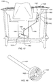
- FIG. 1 is a perspective view of a prior art catalyst assisted wood heater with a bypass mechanism disposed in a closed position;
- FIG. 2 is a partial perspective view, partially cut away, of the prior art catalyst assisted wood heater of FIG. 1 ;
- FIG. 3 is a perspective view of the prior art catalyst assisted wood heater of FIG. 1 with the bypass mechanism disposed in an open position;
- FIG. 4 is a partial perspective view, partially cut away, of the prior art catalyst assisted wood heater of FIG. 3 ;
- FIG. 5 is a perspective view, partially cut away, of a non-bypassable catalyst assisted appliance according to an embodiment of the present disclosure
- FIG. 6 is an enlarged perspective view of detail 6 of FIG. 5 ;
- FIG. 7 is a cross-sectional view taken along line 7 - 7 in FIG. 1 ;
- FIG. 8 is a cross-sectional view taken along line 8 - 8 in FIG. 1 with the loading door disposed in a closed position;
- FIG. 9 is a cross-sectional view similar to FIG. 8 with the loading door disposed in an open position;
- FIG. 10 is a top perspective view of the non-bypassable catalyst assisted appliance of FIG. 5 with a top removed;
- FIG. 11 is a top perspective view of the non-bypassable catalyst assisted wood heater of FIG. 5 with a top and a shroud removed;
- FIG. 12 is a perspective view, partially cut away, of a non-bypassable catalyst assisted appliance according to an embodiment of the present disclosure
- FIG. 13 is an enlarged perspective view of detail 13 of FIG. 12 ;
- FIG. 14 is a cross-sectional view taken along line 14 - 14 in FIG. 1 ;
- FIG. 15 is a cross-sectional view taken along line 15 - 15 in FIG. 1 with the loading door disposed in a closed position;
- FIG. 16 is a cross-sectional view similar to FIG. 8 with the loading door disposed in an open position;
- FIG. 17 is a rear elevational view of the non-bypassable catalyst assisted appliance of FIG. 8 ;
- FIG. 18 is a perspective view of the bimetallic coil disposable in the temperature sensing and automatic controlling unit of the non-bypassable catalyst assisted appliance of FIG. 8 ;
- FIG. 19 is a method for operating non-bypassable catalyst assisted appliance according to an embodiment of the present disclosure.
- FIG. 20 is a method for fabricating a non-bypassable catalyst assisted appliance for use in producing heat according to an embodiment of the present disclosure.
- the present disclosure is directed to a non-bypassable catalyst assisted appliances such as non-bypassable catalyst assistant wood heaters where a catalytic combustor does not result in substantially restricted air flow and consequent need for a catalyst bypass mode and/or mechanism as is typical in prior art catalytic assisted wood stoves.
- a catalyst bypass mode and/or mechanism as is typical in prior art catalytic assisted wood stoves.
- FIG. 5 illustrates a non-bypassable catalyst assisted appliance according to an embodiment of the present disclosure.
- a non-bypassable catalyst assisted appliance may be configured as a wood heater or vented wood fireplace heater.
- a non-bypassable catalyst assisted wood heater 100 may generally include a housing 112 supported by a plurality of feet 114 , and a door 116 .
- Housing 112 may include a front wall 120 having a door opening which is covered by door 116 , a pair of sidewalls 122 (only one of which is shown in FIG. 5 ), a top wall 124 , and a rear wall, and bottom wall (not shown in FIG. 5 ).
- a flue 119 in fluid communication via an exit opening 118 ( FIGS. 8 and 9 ) with the inside of the housing may be operably connected to a chimney in a building such as a home.
- non-bypassable catalyst assisted wood heater 100 further includes a catalytic converter or catalytic combustor 200 that may extend or be disposed above a combustion chamber 300 ( FIG. 7 ) in housing 112 .
- catalytic combustor 200 may span between the side walls of the housing and between the front wall and the rear wall of the housing.
- Catalytic combustor 200 may have a width W ( FIG. 7 ), a height H ( FIG. 7 ), and a depth D ( FIG. 8 ).
- catalytic combustor 200 may have a honeycomb-like configuration.
- catalytic combustor 200 may be formed from a plurality of spaced-apart corrugated sheets 210 .
- a plurality of supports 220 may operably support the plurality of spaced-apart corrugated sheets 210 . Adjacent upper and lower surfaces of the corrugated sheets may be spaced from each other.
- a diffuser or screen 400 having a plurality of apertures may be placed in front of the entrance to the combustor to act as a filter to prevent paper particles, ash, etc. from entering and physically clogging passages in the catalytic combustor.
- the diffuser or screen may prevent or minimize flame impingement on a catalyst combustor.
- Catalytic combustor 200 may define a catalytic combustor inlet 250 , and a catalytic combustor outlet 252 ( FIG. 8 ).
- Catalytic combustor 200 may be supported on a platform 310 ( FIG. 8 ) which operably forms a top surface of combustion chamber 300 .
- platform 310 may be an upper wall of an air supply manifold operable for providing a secondary supply of air S ( FIG. 8 ) to combustion chamber 300 .
- a primary supply of air P FIG. 8
- Primary supply of air P and secondary supply of air S may be introduced at the bottom of the housing via an air inlet opening 111 . It will be appreciated that the separate or a plurality of inlet opening may be provided for primary supply of air and secondary supply of air.
- a shroud 270 may be disposed around catalytic combustor 200 so that the exhaust of gas from combustion chamber 300 ( FIG. 8 ) is directed to catalytic combustor inlet 250 of catalytic combustor 200 , through catalytic combustor 200 , and out catalytic combustor outlet 252 ( FIG. 8 ) of catalytic combustor 200 , and into flue 119 .
- Shroud 270 may aid in keeping the catalyst combustor warm, control the flow through the catalyst combustor, and/or insulate to keep the top wall of the housing not as hot.
- the shroud or enclosure may be of sized and configured to maintain a suitable temperature environment to encourage and sustain catalyst activation.
- non-bypassable catalyst assisted wood heater 100 with loading door 116 disposed in a closed position may have a single flow path SFP 1 for exhausting gas from combustion chamber 300 to exit opening 118 into flue 119 ( FIG. 5 ).
- single flow path SFP 1 of combustion gas may pass through combustor inlet 250 of catalytic combustor 200 , between platform 310 and shroud 270 ( FIG. 10 ) and through catalytic combustor 200 , out catalytic combustor outlet 252 of catalytic combustor 200 , and to exit opening 118 into flue 119 .
- FIG. 9 illustrates non-bypassable catalyst assisted wood heater 100 with loading door 116 disposed in an open position such as when starting a fire in combustion chamber 300 or when loading fuel such as wood through door opening 117 onto an existing fire in combustion chamber 300 .
- loading door 116 open, a flow of ambient air F is able to pass through door opening 117 and enter combustion chamber 300 .
- catalyst assisted wood heater 100 may define a single flow path SFP 2 for exhausting a combination of flow of ambient air F entering non-bypassable catalyst assisted heater 100 through door opening 117 and combustion gas from combustion chamber 300 .
- single flow path SFP 2 of the combination of flow of ambient air and combustion gas may pass through combustor inlet 250 of catalytic combustor 200 , between platform 310 and shroud 270 and through catalytic combustor 200 , and out catalytic combustor outlet 252 of catalytic combustor 200 , and exit opening 118 and into flue 119 .
- catalytic combustor 200 is sized and configured to not substantially restrict the above-described flows therethrough with loading door 116 disposed in either a closed position or in an open position compared to the restricted flow in conventional catalytic combustors in catalytic assisted wood stoves.
- catalytic combustor 200 may be sized and configured to not substantially restrict the flow of combustion gas so that smoke is not undesirably exhausted out door opening 117 and into for example, a room when door 116 is opened.
- the technique of the present disclosure eliminates a bypass such as a plate, damper, etc. and associated mechanisms consequently resulting in a catalytic assisted that is always passively operating in a “clean burn” mode.
- the technique of the present disclosure avoids intentional or unintentional operation in a “dirty burn” mode, which can be heavily polluting.
- catalytic combustor 200 may be optimized and configured to have a longer travel or flow path, e.g., depth D ( FIG. 8 ), larger inlet and outlet, e.g., height H width W ( FIG. 7 ), and/or a larger open area or less cell density across the flow path compared to the restricted flow in conventional catalytic combustors in catalytic assisted wood stoves having a shorter depth or flow path, smaller inlet and outlet, and a more dense cell density across the flow path which restricts the flow therethrough.
- a longer travel or flow path e.g., depth D ( FIG. 8 )
- larger inlet and outlet e.g., height H width W ( FIG. 7 )
- a larger open area or less cell density across the flow path compared to the restricted flow in conventional catalytic combustors in catalytic assisted wood stoves having a shorter depth or flow path, smaller inlet and outlet, and a more dense cell density across the flow path which restricts the flow therethrough.
- FIGS. 12-16 illustrate a non-bypassable catalyst assisted appliance according to an embodiment of the present disclosure.
- a non-bypassable catalyst assisted wood heater 1000 may be essentially the same as non-bypassable catalyst assisted wood heater 100 with the exception of the configuration of the catalytic converter or catalytic combustor, and the location of the introduction of a secondary supply of air.
- non-bypassable catalyst assisted wood heater 1000 may include a catalytic converter or catalytic combustor 1200 that may extend or be disposed above a combustion chamber 1300 ( FIGS. 13-15 ) in a housing 1112 .
- catalytic combustor 200 may span between the side walls of the housing and between the front wall and the rear wall of the housing.
- catalytic combustor 1200 may have a honeycomb-like configuration.
- catalytic combustor 1200 may be formed from a plurality of spaced-apart corrugated sheets 1210 operably stacked one on top of another without supporting spacers. Adjacent upper and lower surfaces of the corrugated sheets may be spaced from each other.
- a diffuser or screen 1400 having a plurality of apertures may be placed in front of the entrance to the combustor to act as a filter to prevent paper particles, ash, etc. from entering and physically clogging passages in the catalytic combustor.
- the diffuser or screen may prevent or minimize flame impingement on a catalyst combustor.
- non-bypassable catalyst assisted wood heater 1100 with loading door 1116 disposed in a closed position may have a single flow path SFP 1 ′ for exhausting gas from combustion chamber 1300 to an exit opening 1118 into a flue 1119 .
- single flow path SFP 1 ′ of combustion gas may pass through combustor inlet 1250 of catalytic combustor 200 , between a platform 1310 and a shroud 1270 or a top of the housing and through catalytic combustor 1200 , out catalytic combustor outlet 1252 of catalytic combustor 1200 , and exit opening 1118 into flue 1119 ( FIG. 12 ).
- Primary supply of air P′ may be introduced at the bottom of the housing via an air inlet opening 1113 .
- Secondary supply of air S′ may be introduced at a location different from the primary supply of air P′.
- secondary supply of air S′ may be introduced via an air inlet opening 1115 at a location behind housing 1112 .
- FIG. 16 illustrates non-bypassable catalyst assisted wood heater 1000 with loading door 1116 disposed in an open position such as when starting a fire in combustion chamber 1300 or when loading fuel such as wood through door opening 1117 onto an existing fire in combustion chamber 1300 .
- loading door 1116 With loading door 1116 open, a flow of ambient air F′ is able to pass through door opening 1117 and enter combustion chamber 1300 .
- catalyst assisted wood heater 1000 may define a single flow path SFP 2 ′ for exhausting a combination of flow of ambient air F′ entering non-bypassable catalyst assisted heater 1000 through door opening 1117 and combustion gas from combustion chamber 1300 .
- single flow path SFP 2 ′ of the combination of flow of ambient air and combustion gas may pass through combustor inlet 1250 of catalytic combustor 1200 , between platform 1310 and shroud 1270 and through catalytic combustor 1200 , out catalytic combustor outlet 1252 of catalytic combustor 1200 , and exit opening 1118 into flue 1119 ( FIG. 12 ).
- an automated secondary air control system 1500 may be provided for regulating the amount of supply of secondary air into the non-bypassable catalyst assisted wood heater.
- a purpose of system 1500 may be to regulate the amount of secondary air provided to support secondary combustion.
- System 1500 may regulate the amount of secondary air supplied at particular stages of a burn cycle of a load of fuel in order to optimize combustion and emissions reduction performance. For example, system 1500 may provide a decreased flow of secondary air when the non-bypassable catalyst assisted wood heater is being started, or an increased flow of secondary air when the non-bypassable catalyst assisted wood heater is at an operating temperature.
- System 1500 may generally include a movable secondary air cover 1510 , a temperature sensing and automatic controlling unit 1520 operably connected to cover 1510 via a cable 1550 .
- Cover 1510 is located over secondary air opening 1115 ( FIG. 15 ).
- an upper edge portion of the cover may be pivotally attached via a pivot or a hinge to the rear of non-bypassable catalyst assisted wood heater 1000 to allows for opening and closing secondary air opening 1115 ( FIG. 15 ).
- a lower end 1551 of cable 1550 may be operably attached to cover 1510 .
- lower end 1551 may be operably attached to a member 1502 , which member extends outwardly from a rear surface of cover 1500 .
- Temperature sensing and automatic controlling unit 1520 may include a bi-metallic coil 1525 (best shown in FIG. 18 ) and a metal rod 1527 located in an enclosure 1522 at the top rear of non-bypassable catalyst assisted wood heater 1000 .
- One end of the bi-metallic coil is attached to one end of the metal rod.
- the other end of the metal rod is disposed in proximity to the catalyst such as in the gas exhausted out of the catalyst. The purpose of the rod is to encourage more efficient heat transfer to the bi-metallic coil.
- Bi-metallic coil 1525 An end 1526 ( FIG. 18 ) of bi-metallic coil 1525 is attached to an upper end 1553 of cable 1550 .
- Bi-metallic coil 1525 is actuated, i.e., the coil either expands or contracts in a spiraling motion, in reaction to heat produced by or in reaction to varying temperatures in non-bypassable catalyst assisted wood heater 1000 .
- the motion of the cable is transferred via the cable into movement of the cover.
- the positioning of cable 1550 may be provided by passing through tubes 1560 and 1562 operably fixedly attached to the rear of non-bypassable catalyst assisted wood heater 1000 .
- non-bypassable catalyst assisted wood heater 1000 When non-bypassable catalyst assisted wood heater 1000 is started with a new fire, secondary air cover 1510 is disposed in a closed position. As non-bypassable catalyst assisted wood heater 1000 begins to increase in temperature, and when catalyst 1200 ( FIG. 16 ) has been operating in proximity of about 1,000 degrees Fahrenheit (about 538 degrees Celsius), bi-metal coil 1525 ( FIG. 18 ) will have begun reacting to the heat generated by the catalyst, and thus, begin to pull on cable 1550 , which will begin to open secondary air cover 1510 . Typically once non-bypassable catalyst assisted wood heater 1000 is up to a substantial operating condition the secondary air will be open to some degree dependent primarily on the burn rate.
- bypassable catalyst assisted wood heater The hotter the bypassable catalyst assisted wood heater is operating and the more fuel being consumed per unit of time, the further open the secondary air cover will be disposed. It will be appreciated that other forms of automated control and/or opening/closing of the secondary air flow may be suitably provided. For example, a sliding cover may be provided.
- catalytic combustor 1200 is sized and configured to not substantially restrict the above-described flows therethrough with loading door 1116 ( FIG. 15 ) disposed in either a closed position or in an open position compared to the restricted flow in conventional catalytic combustors in catalytic assisted wood stoves.
- catalytic combustor 1200 may be sized and configured to not substantially restrict the flow of combustion gas so that smoke is not undesirably exhausted out the door opening and into for example, a room when the loading door is opened.
- the technique of the present disclosure eliminates a bypass such as a plate, damper, etc.
- the technique of the present disclosure avoids intentional or unintentional operation in a “dirty burn” mode, which can be heavily polluting.
- a non-bypassable catalyst assisted appliance may include an optimized catalytic combustor sized and configured such as the number and spacing of layer forming the catalyst combustor based on various variables, such as the size and configuration of a housing, size and configuration of a combustion chamber, and/or a size, configuration, and/or location of a loading door opening, etc.
- a primary factor of in determining a size and configuration of a catalyst combustor may be the size of the loading door/opening combined with the natural fluid flow within a housing or firebox and its associated geometry.
- the general design of a catalyst combustor may remain consistent with the variable being an overall cross-sectional area that the catalyst occupies dependent on the aforementioned variables of flow and door opening. For example, a smaller loading door/opening may allow for a smaller catalytic combustor.
- a non-bypassable catalyst assisted appliance may include a catalytic combustor according to the present disclosure having a width of about 15 inches to about 25 inches, a height of about 3 inches to about 5 inches, and a depth of about 4 inches to about 6 inches.
- a non-bypassable catalyst assisted appliance may include a catalytic combustor according to the present disclosure having a width of about 20 inches, a height of about 4 inches, and a depth of about 5 inches.
- the catalyst combustor may be formed from a catalyst made from Fecralloy, a high temperature very thin walled metal catalyst substrate with gama alumina that is configured to provide for minimum air flow resistance.
- a catalyst combustor may be formed from nickel chromium cobalt molybdenum alloy such as an INCONEL alloy coated with the catalyst.
- a catalytic combustor may be any catalytic combustor such as a one-piece cellular ceramic honeycomb unit.
- the various structures of the catalyst combustors may be coated with a noble metal catalyst such as a platinum metal.
- a sieve or mixing screen or similar device prior to the catalyst may be employed to slow down the gas stream flow and increase residence time for combustion.
- a sieve or mixing screen may be interlocked with the door versus manual actuation.
- non-bypassable catalyst assisted appliance such as a wood heater provides for taking advantage of both the aspects of non-catalytic technology and catalytic technology.
- the appliance may transition between being more reliant on one or the other technologies depending on what stage of the burn cycle it is in. For example, when a new load of fuel is added to the firebox it is like adding an ice cube. The whole appliance cools down and then tries to recover thermal momentum. During this period, there really is no need for much secondary air as the CO in the exhaust is too cool to ignite, as is relied upon in typical secondary baffle non-catalytic technology.
- the catalyst will work under those conditions to improve and clean up the exhaust as it is not reliant on the high temperature and CO reaction with secondary air. So, the catalyst is doing the work in the early part of the burn cycle to reduce emissions. Once the stove recovers thermal momentum, the secondary baffle components increases in secondary combustion activity and assumes a large proportion of the clean burn emissions reduction.
- the automated secondary air control may allow for optimizing when and how much secondary air is required. It will also be appreciated that in non-bypassable catalyst assisted appliance 100 ( FIG. 5 , and in other stoves such as some smaller stoves, the secondary air might possibly be a fixed amount.
- FIG. 17 illustrates a method 2000 for operating a non-bypassable catalyst assisted appliance to produce heat.
- Method 2000 includes, for example, at 2100 opening a door of the non-bypassable catalyst assisted appliance, and at 2200 loading wood through the opening and into the combustion chamber.
- At 2300 while the door is open ambient air and gas is exhausted from a combustion chamber through a catalyst and out a flue.
- the door of the non-bypassable catalyst assisted appliance is closed, and at 2500 gas is exhausted from the combustion chamber through the catalyst and out a flue.
- the method may include the non-bypassable catalyst assisted appliance not including a catalyst bypass.
- the method may include providing a sufficient draft through the catalyst combustor so that combustion gas is inhibited from passing through the door opening when said door is open.
- the method may include, when loading fuel through the loading door opening, gas from the combustion chamber is prevented from exiting the loading door opening.
- FIG. 18 illustrates a method 3000 for fabricating a non-bypassable catalyst assisted appliance for use in producing heat.
- Method 3000 includes, for example, at 3100 configuring a housing having a combustion chamber therein, a loading door opening coverable by a door for loading fuel into the combustion chamber, an air inlet opening for receiving an air supply to the combustion chamber, and an exit opening connectable to a flue, and at 3200 optimizing a size and configuration of a catalyst combustor disposed between the combustion chamber and the exit opening so that when the door is disposed in a closed position covering the loading door opening, gas from the combustion chamber is directed through the catalyst combustor, and out the flue, and when the door is disposed in an open position allowing loading of fuel through the loading door opening to the combustion chamber, ambient air entering the loading door opening and gas from the combustion chamber are directed through the catalyst combustor, and out the flue.
- the method may include the non-bypassable catalyst assisted appliance not including a catalyst bypass.
- the method may include the
- a benefit of the present disclosure is non-bypassable catalytic assisted appliances that do not require and eliminate a catalyst bypass mode or damper to overcome pressure drop across the catalyst combustor so that the catalyst assisted appliances of the present disclosure is passively maintained in a clean burn mode at all time.
- Such a configuration reduces the possibility of a user intentionally, or unintentionally or inadvertently operating the catalytic assisted appliance in an unclean mode, which can result in increased particulate and gaseous emissions.
- Another benefit of the present disclosure is non-bypassable catalytic assisted appliances that have a higher velocity of flow through the catalyst combustor compared to conventional catalyst combustors. Such increases flow rate may result in inhibiting the accumulation of particulate on the catalyst combustor resulting is less of a need or extending the time in which to clean the catalyst combustor.
- Another benefit of the present disclosure is non-bypassable catalytic assisted appliances that allows certification in a non-bypass mode.
- catalytic assisted appliance having a bypass, it is necessity to operate with the bypass open during safety certification testing.
- Bypass open operation typically results in larger clearances to combustibles. Elimination of a bypass mode and associated test requirement may result in more market favorable clearances to combustibles.
- Another benefit of the present disclosure is non-bypassable catalytic assisted appliances that may be able to reduce particulate emissions so as to be in compliance with EPA year 2020 pending regulations.
- non-bypassable catalytic assisted appliances that may be passively engaged at all times and that provides no open bypass dirty burn mode as is typical with current catalyst designs.
- the no bypass configuration may be beneficial to achieving desirable rear clearances, lower flow resistance may reduce potential for back puffing, less difficulty in obtaining a robust fire started, and/or less issues with ash plugging.
- a method or device that “comprises”, “has”, “includes” or “contains” one or more steps or elements possesses those one or more steps or elements, but is not limited to possessing only those one or more steps or elements.
- a step of a method or an element of a device that “comprises”, “has”, “includes” or “contains” one or more features possesses those one or more features, but is not limited to possessing only those one or more features.
- a device or structure that is configured in a certain way is configured in at least that way, but may also be configured in ways that are not listed.
Abstract
Description
Claims (19)
Priority Applications (2)
| Application Number | Priority Date | Filing Date | Title |
|---|---|---|---|
| US15/799,202 US10788216B2 (en) | 2016-11-01 | 2017-10-31 | Non-bypassable catalyst assisted appliances |
| US17/004,413 US11287135B2 (en) | 2016-11-01 | 2020-08-27 | Non-bypassable catalyst assisted appliances |
Applications Claiming Priority (2)
| Application Number | Priority Date | Filing Date | Title |
|---|---|---|---|
| US201662415863P | 2016-11-01 | 2016-11-01 | |
| US15/799,202 US10788216B2 (en) | 2016-11-01 | 2017-10-31 | Non-bypassable catalyst assisted appliances |
Related Child Applications (1)
| Application Number | Title | Priority Date | Filing Date |
|---|---|---|---|
| US17/004,413 Continuation US11287135B2 (en) | 2016-11-01 | 2020-08-27 | Non-bypassable catalyst assisted appliances |
Publications (2)
| Publication Number | Publication Date |
|---|---|
| US20180119959A1 US20180119959A1 (en) | 2018-05-03 |
| US10788216B2 true US10788216B2 (en) | 2020-09-29 |
Family
ID=60473602
Family Applications (2)
| Application Number | Title | Priority Date | Filing Date |
|---|---|---|---|
| US15/799,202 Active 2038-07-29 US10788216B2 (en) | 2016-11-01 | 2017-10-31 | Non-bypassable catalyst assisted appliances |
| US17/004,413 Active US11287135B2 (en) | 2016-11-01 | 2020-08-27 | Non-bypassable catalyst assisted appliances |
Family Applications After (1)
| Application Number | Title | Priority Date | Filing Date |
|---|---|---|---|
| US17/004,413 Active US11287135B2 (en) | 2016-11-01 | 2020-08-27 | Non-bypassable catalyst assisted appliances |
Country Status (6)
| Country | Link |
|---|---|
| US (2) | US10788216B2 (en) |
| EP (2) | EP3535522B1 (en) |
| DK (1) | DK3535522T3 (en) |
| ES (1) | ES2953497T3 (en) |
| PL (1) | PL3535522T3 (en) |
| WO (1) | WO2018085225A1 (en) |
Cited By (1)
| Publication number | Priority date | Publication date | Assignee | Title |
|---|---|---|---|---|
| US11287135B2 (en) * | 2016-11-01 | 2022-03-29 | Jotul As | Non-bypassable catalyst assisted appliances |
Families Citing this family (6)
| Publication number | Priority date | Publication date | Assignee | Title |
|---|---|---|---|---|
| US10228142B2 (en) * | 2017-06-21 | 2019-03-12 | Carroll J. Sanders | Wood-burning stove with internal baffles for increased burn times |
| CN107366901B (en) * | 2017-07-14 | 2019-02-19 | 南京林业大学 | Gasification of biomass combustible gas stablizes environmentally friendly combustion method and environment-friendly type combustion chamber |
| US10646824B2 (en) * | 2018-06-12 | 2020-05-12 | Mainsteam Engineering Corporation | Catalytic cookstove with passive control of draft and method of use |
| CN112691474B (en) * | 2020-12-22 | 2022-09-13 | 山东帅克环保科技有限公司 | Integrated catalytic combustion waste gas treatment device |
| JP2023034800A (en) * | 2021-08-31 | 2023-03-13 | 株式会社エフ・シー・シー | Exhaust gas purification device for wood stove and method for manufacturing the same |
| JP2023034797A (en) * | 2021-08-31 | 2023-03-13 | 株式会社エフ・シー・シー | Exhaust gas purification device for wood stove and method for manufacturing the same |
Citations (12)
| Publication number | Priority date | Publication date | Assignee | Title |
|---|---|---|---|---|
| US4373507A (en) | 1980-10-09 | 1983-02-15 | Jamestown Group | Stove construction |
| US4510918A (en) | 1983-11-28 | 1985-04-16 | Vermont Castings, Inc. | Woodburning heating apparatus |
| US4646712A (en) | 1983-11-28 | 1987-03-03 | Vermont Castings, Inc. | Solid fuel heating appliances |
| US4827852A (en) | 1987-06-01 | 1989-05-09 | Piontkowski Carl F | Catalytic wood stove |
| US6041770A (en) | 1998-05-05 | 2000-03-28 | Erickson; Paul E. | Bi-metallic control device |
| US6216687B1 (en) | 1996-03-22 | 2001-04-17 | The Majestic Products Company | Unvented heating appliance having system for reducing undesirable combustion products |
| US20080041357A1 (en) | 2004-04-15 | 2008-02-21 | Brown Stephen C | Combustion Apparatus for Solid Fuel |
| EP2166287A2 (en) | 2008-12-24 | 2010-03-24 | KAGO-Kamine-Kachelofen GmbH & Co. Deutsche Wärmesysteme KG | Solid fuel fireplace for buildings and a solid fuel fireplace for such |
| WO2011098267A1 (en) | 2010-02-09 | 2011-08-18 | Dr. Pley Environmental Gmbh | Device for treating exhaust gases from a small heating system |
| US20110247533A1 (en) | 2008-12-17 | 2011-10-13 | Frederic Haas | Fume box for a domestic heating appliance using solid fuel |
| US20140311477A1 (en) * | 2013-03-07 | 2014-10-23 | Reginald James Davenport | Control system for monitoring and adjusting combustion performance in a cordwood-fired heating appliance |
| US9170025B2 (en) * | 2010-03-12 | 2015-10-27 | Travis Industries, Inc. | Hybrid wood burning fireplace assembly |
Family Cites Families (19)
| Publication number | Priority date | Publication date | Assignee | Title |
|---|---|---|---|---|
| US4580546A (en) * | 1981-10-28 | 1986-04-08 | Condar Co. | Catalytic stove |
| US4458662A (en) * | 1981-10-28 | 1984-07-10 | Condar Co. | Catalytic stove |
| US4862869A (en) * | 1988-08-08 | 1989-09-05 | N.H.C., Inc. | Low emissions wood burning stove |
| US5050579A (en) * | 1990-04-12 | 1991-09-24 | Vestal Manufacturing Company | Combustor assembly for a fuel-burning room heater |
| US6705310B2 (en) * | 2002-04-10 | 2004-03-16 | Cfm Corporation | Wood burner with improved emissions |
| FR2928846B1 (en) * | 2008-03-20 | 2010-10-22 | Fondis Sa | CATALYST PURIFYING DEVICE FOR GASES AND COMBUSTION FUMES OF A SOLID FUEL HEATING APPARATUS. |
| US9046273B2 (en) * | 2010-01-11 | 2015-06-02 | Jotul North America, Inc. | Methods for operating a top loading wood-fired appliance having a cooperating top-loading door and movable baffle |
| JP2011242120A (en) * | 2010-04-20 | 2011-12-01 | Dutchwest Japan Kk | Combustion catalyst apparatus, and solid fuel combustor |
| AU2012251179B2 (en) * | 2011-05-04 | 2016-07-14 | Jason Joren Jens STEWART | A combustion system |
| JP2013088067A (en) * | 2011-10-20 | 2013-05-13 | Kaneko Agricultural Machinery Co Ltd | Clean heat and hot air-generating device by biomass combustion |
| US8869788B2 (en) * | 2012-02-15 | 2014-10-28 | United States Stove Company | Low emission woodstove |
| DK177552B1 (en) * | 2012-04-27 | 2013-10-07 | Skamol As | Catalytic unit for solid fuel burning stoves |
| US20140093829A1 (en) * | 2012-05-04 | 2014-04-03 | Alex Leonard Johnson | Particulate and co2 reduction system for commercial/residential devices that generate thermal energy |
| JP5700849B2 (en) * | 2012-07-12 | 2015-04-15 | 株式会社岡本 | Wood-burning stove |
| JP5985995B2 (en) * | 2013-01-16 | 2016-09-06 | 株式会社岡本 | Wood-burning stove |
| JP2014238208A (en) * | 2013-06-07 | 2014-12-18 | 株式会社新宮商行 | Smoke exhaust device and heating system mounted with the same |
| US10041682B1 (en) * | 2013-11-15 | 2018-08-07 | University Of Maryland | High efficiency solid fuel burning stove with optimized burning conditions and low level of emission |
| US20150253006A1 (en) * | 2014-03-05 | 2015-09-10 | Lance Carl Grace | Emission reduction device for a wood heater |
| EP3535522B1 (en) | 2016-11-01 | 2023-05-31 | Jøtul AS | Non-bypassable catalyst assisted appliances |
-
2017
- 2017-10-31 EP EP17804696.7A patent/EP3535522B1/en active Active
- 2017-10-31 DK DK17804696.7T patent/DK3535522T3/en active
- 2017-10-31 PL PL17804696.7T patent/PL3535522T3/en unknown
- 2017-10-31 WO PCT/US2017/059192 patent/WO2018085225A1/en unknown
- 2017-10-31 US US15/799,202 patent/US10788216B2/en active Active
- 2017-10-31 ES ES17804696T patent/ES2953497T3/en active Active
- 2017-10-31 EP EP23176041.4A patent/EP4235028A3/en active Pending
-
2020
- 2020-08-27 US US17/004,413 patent/US11287135B2/en active Active
Patent Citations (12)
| Publication number | Priority date | Publication date | Assignee | Title |
|---|---|---|---|---|
| US4373507A (en) | 1980-10-09 | 1983-02-15 | Jamestown Group | Stove construction |
| US4510918A (en) | 1983-11-28 | 1985-04-16 | Vermont Castings, Inc. | Woodburning heating apparatus |
| US4646712A (en) | 1983-11-28 | 1987-03-03 | Vermont Castings, Inc. | Solid fuel heating appliances |
| US4827852A (en) | 1987-06-01 | 1989-05-09 | Piontkowski Carl F | Catalytic wood stove |
| US6216687B1 (en) | 1996-03-22 | 2001-04-17 | The Majestic Products Company | Unvented heating appliance having system for reducing undesirable combustion products |
| US6041770A (en) | 1998-05-05 | 2000-03-28 | Erickson; Paul E. | Bi-metallic control device |
| US20080041357A1 (en) | 2004-04-15 | 2008-02-21 | Brown Stephen C | Combustion Apparatus for Solid Fuel |
| US20110247533A1 (en) | 2008-12-17 | 2011-10-13 | Frederic Haas | Fume box for a domestic heating appliance using solid fuel |
| EP2166287A2 (en) | 2008-12-24 | 2010-03-24 | KAGO-Kamine-Kachelofen GmbH & Co. Deutsche Wärmesysteme KG | Solid fuel fireplace for buildings and a solid fuel fireplace for such |
| WO2011098267A1 (en) | 2010-02-09 | 2011-08-18 | Dr. Pley Environmental Gmbh | Device for treating exhaust gases from a small heating system |
| US9170025B2 (en) * | 2010-03-12 | 2015-10-27 | Travis Industries, Inc. | Hybrid wood burning fireplace assembly |
| US20140311477A1 (en) * | 2013-03-07 | 2014-10-23 | Reginald James Davenport | Control system for monitoring and adjusting combustion performance in a cordwood-fired heating appliance |
Non-Patent Citations (14)
| Title |
|---|
| "How Lopi Wood Stoves Work", Travis Industries, 4 pages, as early as 2015. |
| Aspen Non-Catalytic Wood Stove and Intrepid II Catalytic Wood Stove Brochure, printout available on Oct. 16, 2017, at http://downloads.hearthnhome.com/brochures/VC1608_CatNonCatStoves.pdf, 5 pages, 2015. |
| Blaze King Ashford 20.1, Operation and Installation Manual, Valley Comfort Systems Inc., Canada, 40 pages, Sep. 10, 2014. |
| Blaze King Ashford, Operating Instructions, 1 page, May 25, 2015. |
| Defiant Encore Owner's Guide, Model #2190, available from Vermont Castings, Inc., www.vermontcastings.com, 31 pages, Apr. 1994. |
| Dutchwest Convection Heater, Damper Function, 3 pages, at least as early as Feb. 2012. |
| International Search Report and Written Opinion, International Application No. PCT/US2017/059192, 12 pages, dated Jan. 24, 2018. |
| Intrepid II Wood Burning Stove-Homeowner's Installation & Operating Manual, Model 1990, Vermont Castings, Inc., 40 pages, Jul. 2013. |
| Intrepid II Wood Burning Stove—Homeowner's Installation & Operating Manual, Model 1990, Vermont Castings, Inc., 40 pages, Jul. 2013. |
| Intrepid II Woodburning Stove Model 1990, Homeowner's Installation and Operating Manual, Vermont Castings, Inc., 40 pages, 1990. |
| Intrepid II Woodburning Stove Model 1990, Homeowner's Installation and Operating Manual, Vermont Castings, Inc., self regulating secondary air supply, pp. 1, 4, 33, and 35, 1990. |
| MF Fire Catalyst Wood Stove Owner's Manual, 25 pages, at least as early as 2013. |
| MF Fire Catalyst Wood Stove, 3 pages, May 21, 2016. |
| Purinton et al., "Non-Bypassable Catalyst Assisted Appliances", International Application Serial No. PCT/US17/59192, filed Oct. 31, 2017, 41 pages. |
Cited By (1)
| Publication number | Priority date | Publication date | Assignee | Title |
|---|---|---|---|---|
| US11287135B2 (en) * | 2016-11-01 | 2022-03-29 | Jotul As | Non-bypassable catalyst assisted appliances |
Also Published As
| Publication number | Publication date |
|---|---|
| EP4235028A2 (en) | 2023-08-30 |
| EP3535522A1 (en) | 2019-09-11 |
| EP3535522B1 (en) | 2023-05-31 |
| PL3535522T3 (en) | 2023-09-25 |
| US20180119959A1 (en) | 2018-05-03 |
| US11287135B2 (en) | 2022-03-29 |
| WO2018085225A1 (en) | 2018-05-11 |
| EP4235028A3 (en) | 2023-12-27 |
| US20200393133A1 (en) | 2020-12-17 |
| ES2953497T3 (en) | 2023-11-13 |
| DK3535522T3 (en) | 2023-08-21 |
Similar Documents
| Publication | Publication Date | Title |
|---|---|---|
| US11287135B2 (en) | Non-bypassable catalyst assisted appliances | |
| US7644711B2 (en) | Spark arrestor and airflow control assembly for a portable cooking or heating device | |
| US6067979A (en) | Combustion system | |
| US10677495B2 (en) | Stove | |
| US4368721A (en) | Woodburning stove | |
| JP3385404B2 (en) | Garbage incinerator | |
| AU780403B2 (en) | Wood burning stove having pivoting baffle and method | |
| US5413088A (en) | Wood burning heating unit | |
| GB2100419A (en) | A stove | |
| JP2017203614A (en) | Combustion device | |
| FI119077B (en) | Hearth | |
| JP4678693B2 (en) | grill | |
| KR20230121426A (en) | Multi-purpose stove that induces complete combustion | |
| US3044421A (en) | Combination gas fired incinerator and charcoal broiler | |
| KR102414733B1 (en) | Heater for burning firewood tree by fire | |
| JP7015502B1 (en) | Wood-burning stove | |
| JPS61143608A (en) | Heater | |
| JP7438880B2 (en) | grill | |
| JP6706829B2 (en) | Wood-burning stove | |
| WO2010053359A2 (en) | Fireplace, and method for operating such a fireplace | |
| BE1023129B1 (en) | Fireplace | |
| JP3150250B2 (en) | Double side grill | |
| WO2019240830A1 (en) | Catalytic cookstove with passive control of draft and method of use | |
| UA55147A (en) | Heater furnace | |
| CA2332168A1 (en) | Wood heater |
Legal Events
| Date | Code | Title | Description |
|---|---|---|---|
| FEPP | Fee payment procedure |
Free format text: ENTITY STATUS SET TO UNDISCOUNTED (ORIGINAL EVENT CODE: BIG.); ENTITY STATUS OF PATENT OWNER: LARGE ENTITY |
|
| AS | Assignment |
Owner name: JOTUL AS, NORWAY Free format text: ASSIGNMENT OF ASSIGNORS INTEREST;ASSIGNORS:PURINTON, ROGER W.;SPENCER, SHANE L.;REEL/FRAME:044191/0359 Effective date: 20171019 |
|
| AS | Assignment |
Owner name: JOTUL US, NORWAY Free format text: CORRECTIVE ASSIGNMENT TO CORRECT THE PCT NUMBER PREVIOUSLY RECORDED AT REEL: 044191 FRAME: 0359. ASSIGNOR(S) HEREBY CONFIRMS THE ASSIGNMENT;ASSIGNORS:PURINTON, ROGER W.;SPENCER, SHANE L.;REEL/FRAME:045967/0624 Effective date: 20171019 |
|
| STPP | Information on status: patent application and granting procedure in general |
Free format text: DOCKETED NEW CASE - READY FOR EXAMINATION |
|
| AS | Assignment |
Owner name: JOTUL AS, NORWAY Free format text: CORRECTIVE ASSIGNMENT TO CORRECT THE ASSIGNEE NAME PREVIOUSLY RECORDED AT REEL: 045967 FRAME: 0624. ASSIGNOR(S) HEREBY CONFIRMS THE ASSIGNMENT;ASSIGNORS:PURINTON, ROGER W.;SPENCER, SHANE L.;REEL/FRAME:046376/0311 Effective date: 20171019 |
|
| STPP | Information on status: patent application and granting procedure in general |
Free format text: NON FINAL ACTION MAILED |
|
| STPP | Information on status: patent application and granting procedure in general |
Free format text: NOTICE OF ALLOWANCE MAILED -- APPLICATION RECEIVED IN OFFICE OF PUBLICATIONS |
|
| STPP | Information on status: patent application and granting procedure in general |
Free format text: PUBLICATIONS -- ISSUE FEE PAYMENT VERIFIED |
|
| STCF | Information on status: patent grant |
Free format text: PATENTED CASE |
|
| MAFP | Maintenance fee payment |
Free format text: PAYMENT OF MAINTENANCE FEE, 4TH YEAR, LARGE ENTITY (ORIGINAL EVENT CODE: M1551); ENTITY STATUS OF PATENT OWNER: LARGE ENTITY Year of fee payment: 4 |