US10787113B2 - Vehicle front headlight device - Google Patents
Vehicle front headlight device Download PDFInfo
- Publication number
- US10787113B2 US10787113B2 US16/372,825 US201916372825A US10787113B2 US 10787113 B2 US10787113 B2 US 10787113B2 US 201916372825 A US201916372825 A US 201916372825A US 10787113 B2 US10787113 B2 US 10787113B2
- Authority
- US
- United States
- Prior art keywords
- light source
- vehicle
- timing
- switched
- light
- Prior art date
- Legal status (The legal status is an assumption and is not a legal conclusion. Google has not performed a legal analysis and makes no representation as to the accuracy of the status listed.)
- Expired - Fee Related
Links
Images


Classifications
-
- B—PERFORMING OPERATIONS; TRANSPORTING
- B60—VEHICLES IN GENERAL
- B60Q—ARRANGEMENT OF SIGNALLING OR LIGHTING DEVICES, THE MOUNTING OR SUPPORTING THEREOF OR CIRCUITS THEREFOR, FOR VEHICLES IN GENERAL
- B60Q1/00—Arrangement of optical signalling or lighting devices, the mounting or supporting thereof or circuits therefor
- B60Q1/02—Arrangement of optical signalling or lighting devices, the mounting or supporting thereof or circuits therefor the devices being primarily intended to illuminate the way ahead or to illuminate other areas of way or environments
- B60Q1/04—Arrangement of optical signalling or lighting devices, the mounting or supporting thereof or circuits therefor the devices being primarily intended to illuminate the way ahead or to illuminate other areas of way or environments the devices being headlights
- B60Q1/14—Arrangement of optical signalling or lighting devices, the mounting or supporting thereof or circuits therefor the devices being primarily intended to illuminate the way ahead or to illuminate other areas of way or environments the devices being headlights having dimming means
- B60Q1/1415—Dimming circuits
- B60Q1/1423—Automatic dimming circuits, i.e. switching between high beam and low beam due to change of ambient light or light level in road traffic
- B60Q1/143—Automatic dimming circuits, i.e. switching between high beam and low beam due to change of ambient light or light level in road traffic combined with another condition, e.g. using vehicle recognition from camera images or activation of wipers
-
- B—PERFORMING OPERATIONS; TRANSPORTING
- B60—VEHICLES IN GENERAL
- B60Q—ARRANGEMENT OF SIGNALLING OR LIGHTING DEVICES, THE MOUNTING OR SUPPORTING THEREOF OR CIRCUITS THEREFOR, FOR VEHICLES IN GENERAL
- B60Q1/00—Arrangement of optical signalling or lighting devices, the mounting or supporting thereof or circuits therefor
- B60Q1/02—Arrangement of optical signalling or lighting devices, the mounting or supporting thereof or circuits therefor the devices being primarily intended to illuminate the way ahead or to illuminate other areas of way or environments
- B60Q1/04—Arrangement of optical signalling or lighting devices, the mounting or supporting thereof or circuits therefor the devices being primarily intended to illuminate the way ahead or to illuminate other areas of way or environments the devices being headlights
- B60Q1/06—Arrangement of optical signalling or lighting devices, the mounting or supporting thereof or circuits therefor the devices being primarily intended to illuminate the way ahead or to illuminate other areas of way or environments the devices being headlights adjustable, e.g. remotely-controlled from inside vehicle
- B60Q1/08—Arrangement of optical signalling or lighting devices, the mounting or supporting thereof or circuits therefor the devices being primarily intended to illuminate the way ahead or to illuminate other areas of way or environments the devices being headlights adjustable, e.g. remotely-controlled from inside vehicle automatically
- B60Q1/085—Arrangement of optical signalling or lighting devices, the mounting or supporting thereof or circuits therefor the devices being primarily intended to illuminate the way ahead or to illuminate other areas of way or environments the devices being headlights adjustable, e.g. remotely-controlled from inside vehicle automatically due to special conditions, e.g. adverse weather, type of road, badly illuminated road signs or potential dangers
-
- F—MECHANICAL ENGINEERING; LIGHTING; HEATING; WEAPONS; BLASTING
- F21—LIGHTING
- F21S—NON-PORTABLE LIGHTING DEVICES; SYSTEMS THEREOF; VEHICLE LIGHTING DEVICES SPECIALLY ADAPTED FOR VEHICLE EXTERIORS
- F21S41/00—Illuminating devices specially adapted for vehicle exteriors, e.g. headlamps
- F21S41/20—Illuminating devices specially adapted for vehicle exteriors, e.g. headlamps characterised by refractors, transparent cover plates, light guides or filters
- F21S41/25—Projection lenses
-
- F—MECHANICAL ENGINEERING; LIGHTING; HEATING; WEAPONS; BLASTING
- F21—LIGHTING
- F21S—NON-PORTABLE LIGHTING DEVICES; SYSTEMS THEREOF; VEHICLE LIGHTING DEVICES SPECIALLY ADAPTED FOR VEHICLE EXTERIORS
- F21S41/00—Illuminating devices specially adapted for vehicle exteriors, e.g. headlamps
- F21S41/60—Illuminating devices specially adapted for vehicle exteriors, e.g. headlamps characterised by a variable light distribution
- F21S41/67—Illuminating devices specially adapted for vehicle exteriors, e.g. headlamps characterised by a variable light distribution by acting on reflectors
- F21S41/675—Illuminating devices specially adapted for vehicle exteriors, e.g. headlamps characterised by a variable light distribution by acting on reflectors by moving reflectors
-
- F—MECHANICAL ENGINEERING; LIGHTING; HEATING; WEAPONS; BLASTING
- F21—LIGHTING
- F21V—FUNCTIONAL FEATURES OR DETAILS OF LIGHTING DEVICES OR SYSTEMS THEREOF; STRUCTURAL COMBINATIONS OF LIGHTING DEVICES WITH OTHER ARTICLES, NOT OTHERWISE PROVIDED FOR
- F21V23/00—Arrangement of electric circuit elements in or on lighting devices
- F21V23/003—Arrangement of electric circuit elements in or on lighting devices the elements being electronics drivers or controllers for operating the light source, e.g. for a LED array
-
- F—MECHANICAL ENGINEERING; LIGHTING; HEATING; WEAPONS; BLASTING
- F21—LIGHTING
- F21V—FUNCTIONAL FEATURES OR DETAILS OF LIGHTING DEVICES OR SYSTEMS THEREOF; STRUCTURAL COMBINATIONS OF LIGHTING DEVICES WITH OTHER ARTICLES, NOT OTHERWISE PROVIDED FOR
- F21V23/00—Arrangement of electric circuit elements in or on lighting devices
- F21V23/04—Arrangement of electric circuit elements in or on lighting devices the elements being switches
- F21V23/0442—Arrangement of electric circuit elements in or on lighting devices the elements being switches activated by means of a sensor, e.g. motion or photodetectors
-
- G—PHYSICS
- G02—OPTICS
- G02B—OPTICAL ELEMENTS, SYSTEMS OR APPARATUS
- G02B27/00—Optical systems or apparatus not provided for by any of the groups G02B1/00 - G02B26/00, G02B30/00
- G02B27/09—Beam shaping, e.g. changing the cross-sectional area, not otherwise provided for
- G02B27/0938—Using specific optical elements
- G02B27/095—Refractive optical elements
- G02B27/0955—Lenses
-
- G—PHYSICS
- G02—OPTICS
- G02B—OPTICAL ELEMENTS, SYSTEMS OR APPARATUS
- G02B27/00—Optical systems or apparatus not provided for by any of the groups G02B1/00 - G02B26/00, G02B30/00
- G02B27/09—Beam shaping, e.g. changing the cross-sectional area, not otherwise provided for
- G02B27/0938—Using specific optical elements
- G02B27/0977—Reflective elements
-
- G06K9/00805—
-
- G—PHYSICS
- G06—COMPUTING OR CALCULATING; COUNTING
- G06V—IMAGE OR VIDEO RECOGNITION OR UNDERSTANDING
- G06V20/00—Scenes; Scene-specific elements
- G06V20/50—Context or environment of the image
- G06V20/56—Context or environment of the image exterior to a vehicle by using sensors mounted on the vehicle
- G06V20/58—Recognition of moving objects or obstacles, e.g. vehicles or pedestrians; Recognition of traffic objects, e.g. traffic signs, traffic lights or roads
-
- B—PERFORMING OPERATIONS; TRANSPORTING
- B60—VEHICLES IN GENERAL
- B60Q—ARRANGEMENT OF SIGNALLING OR LIGHTING DEVICES, THE MOUNTING OR SUPPORTING THEREOF OR CIRCUITS THEREFOR, FOR VEHICLES IN GENERAL
- B60Q2300/00—Indexing codes for automatically adjustable headlamps or automatically dimmable headlamps
- B60Q2300/05—Special features for controlling or switching of the light beam
- B60Q2300/056—Special anti-blinding beams, e.g. a standard beam is chopped or moved in order not to blind
-
- B—PERFORMING OPERATIONS; TRANSPORTING
- B60—VEHICLES IN GENERAL
- B60Q—ARRANGEMENT OF SIGNALLING OR LIGHTING DEVICES, THE MOUNTING OR SUPPORTING THEREOF OR CIRCUITS THEREFOR, FOR VEHICLES IN GENERAL
- B60Q2300/00—Indexing codes for automatically adjustable headlamps or automatically dimmable headlamps
- B60Q2300/30—Indexing codes relating to the vehicle environment
- B60Q2300/31—Atmospheric conditions
- B60Q2300/312—Adverse weather
-
- B—PERFORMING OPERATIONS; TRANSPORTING
- B60—VEHICLES IN GENERAL
- B60Q—ARRANGEMENT OF SIGNALLING OR LIGHTING DEVICES, THE MOUNTING OR SUPPORTING THEREOF OR CIRCUITS THEREFOR, FOR VEHICLES IN GENERAL
- B60Q2300/00—Indexing codes for automatically adjustable headlamps or automatically dimmable headlamps
- B60Q2300/30—Indexing codes relating to the vehicle environment
- B60Q2300/32—Road surface or travel path
- B60Q2300/322—Road curvature
-
- F—MECHANICAL ENGINEERING; LIGHTING; HEATING; WEAPONS; BLASTING
- F21—LIGHTING
- F21W—INDEXING SCHEME ASSOCIATED WITH SUBCLASSES F21K, F21L, F21S and F21V, RELATING TO USES OR APPLICATIONS OF LIGHTING DEVICES OR SYSTEMS
- F21W2102/00—Exterior vehicle lighting devices for illuminating purposes
- F21W2102/10—Arrangement or contour of the emitted light
- F21W2102/13—Arrangement or contour of the emitted light for high-beam region or low-beam region
- F21W2102/135—Arrangement or contour of the emitted light for high-beam region or low-beam region the light having cut-off lines, i.e. clear borderlines between emitted regions and dark regions
- F21W2102/16—Arrangement or contour of the emitted light for high-beam region or low-beam region the light having cut-off lines, i.e. clear borderlines between emitted regions and dark regions having blurred cut-off lines
-
- F—MECHANICAL ENGINEERING; LIGHTING; HEATING; WEAPONS; BLASTING
- F21—LIGHTING
- F21W—INDEXING SCHEME ASSOCIATED WITH SUBCLASSES F21K, F21L, F21S and F21V, RELATING TO USES OR APPLICATIONS OF LIGHTING DEVICES OR SYSTEMS
- F21W2102/00—Exterior vehicle lighting devices for illuminating purposes
- F21W2102/20—Illuminance distribution within the emitted light
Definitions
- the present disclosure relates to a vehicle front headlight device.
- Optical units have been proposed in which a rotating mirror is capable of changing a high beam light distribution area (see Japanese Patent No. 5722882). Such optical units are capable of forming a shaded region, such that when there is a vehicle traveling ahead (also referred to as a “leading vehicle” hereafter), a high beam is not illuminated onto the leading vehicle.
- a high beam light distribution area of the optical unit is set such that the high beam is illuminated as far as both ends in a vehicle width direction (vehicle width direction outermost edges) of the leading vehicle and a width of the shaded region is narrowed in order to improve the ability of a vehicle driver to see ahead of the vehicle, when the leading vehicle moves toward the left or right when traveling around a curve, the high beam illuminates onto the leading vehicle, dazzling the driver and so on of the leading vehicle.
- the high beam light distribution area were set such that the high beam was only illuminated as far as positions separated by a predetermined width toward a vehicle width direction outer side from the both ends in the vehicle width direction of the leading vehicle (if a margin were provided at the both ends in the vehicle width direction of the leading vehicle so as to widen a width of the shaded region), the ability of the vehicle driver to see ahead of the vehicle would be reduced.
- the present disclosure obtains a vehicle front headlight device capable of suppressing the driver and so on of a leading vehicle from being dazzled, and also capable of suppressing a reduction in the ability of a vehicle driver to see ahead of the vehicle.
- a vehicle front headlight device of a first aspect of the present disclosure includes a light source, a rotating mirror, a lens, a recognition unit, and a controller.
- the light source is configured to emit light.
- the rotating mirror is configured by plural mirror bodies, that are inclined with respect to an axial direction of a shaft, that are disposed around a circumferential direction of the shaft so as to be capable of being rotationally driven about the shaft, and the rotating mirror rotates while reflecting light emitted by the light source.
- the lens transmits light reflected by the rotating mirror so as to shine the light forward.
- the recognition unit is configured to recognize a leading vehicle traveling ahead.
- the controller controls rotational drive of the rotating mirror, and controls a timing at which the light source is switched off and a timing at which the light source is switched on, such that light is not illuminated onto the leading vehicle recognized by the recognition unit and such that an illumination intensity of light illuminated in a vicinity of both ends in a vehicle width direction of the leading vehicle is lower than an illumination intensity of light illuminated at a vehicle width direction outer side of the vicinity of the both ends in the vehicle width direction of the leading vehicle.
- the controller controls rotational drive of the rotating mirror and controls the timing at which the light source is switched off and the timing at which the light source is switched on, such that light is not illuminated onto the leading vehicle traveling ahead, and such that the illumination intensity of light illuminated in the vicinity of the both ends in the vehicle width direction of the leading vehicle is lower than the illumination intensity of light illuminated at the vehicle width direction outer side of the vicinity of the both ends in the vehicle width direction of the leading vehicle.
- the illumination intensity of the light is low, enabling the driver and so on of the leading vehicle to be suppressed from being dazzled.
- the “vicinity of the both ends in the vehicle width direction of the leading vehicle” refers to a range of no greater than 1 meter toward the vehicle width direction outer side from the ends.
- a vehicle front headlight device of a second aspect of the present disclosure is the vehicle front headlight device of the first aspect, wherein the controller controls so as to change the timing at which the light source is switched off and to change the timing at which the light source is switched on at each revolution of the rotating mirror.
- the controller controls so as to change the timing at which the light source is switched off and to change the timing at which the light source is switched on at each revolution of the rotating mirror. This enables the illumination intensity of the light illuminated in the vicinity of the both ends in the vehicle width direction of the leading vehicle to be appropriately reduced. This thereby enables the driver and so on of the leading vehicle to be effectively suppressed from being dazzled, and enables a reduction in the ability of the vehicle driver to see ahead of the vehicle to be appropriately suppressed.
- a vehicle front headlight device of a third aspect of the present disclosure is the vehicle front headlight device of the second aspect, wherein the controller adjusts so as to change the timing at which the light source is switched off and adjusts so as to change the timing at which the light source is switched on according to a distance to the leading vehicle recognized by the recognition unit.
- the controller adjusts so as to change the timing at which the light source is switched off and adjusts so as to change the timing at which the light source is switched on according to a distance to the leading vehicle recognized by the recognition unit.
- a vehicle front headlight device of a fourth aspect of the present disclosure is the vehicle front headlight device of either the second aspect or the third aspect, wherein the controller adjusts so as to change the timing at which the light source is switched off and adjusts so as to change the timing at which the light source is switched on according to a route found by a car navigation system.
- the controller adjusts so as to change the timing at which the light source is switched off and adjusts so as to change the timing at which the light source is switched on according to the route found by the car navigation system. This thereby enables the driver and so on of the leading vehicle to be more effectively suppressed from being dazzled than in cases in which the timing at which the light source is switched off and the timing at which the light source is switched on is constant, irrespective of the route of the vehicle.
- a vehicle front headlight device of a fifth aspect of the present disclosure is the vehicle front headlight device of any one of the second aspect to the fourth aspect, wherein the controller adjusts so as to change the timing at which the light source is switched off and adjusts so as to change the timing at which the light source is switched on according to weather information detected by a surrounding environment detection device.
- the controller adjusts so as to change the timing at which the light source is switched off and adjusts so as to change the timing at which the light source is switched on according to weather information detected by the surrounding environment detection device. This thereby enables a reduction in the ability of the vehicle driver to see ahead of the vehicle to be more appropriately suppressed than in cases in which the timing at which the light source is switched off and the timing at which the light source is switched on is constant, irrespective of the weather information (weather conditions).
- the vehicle front headlight device of the first aspect enables the driver and so on of the leading vehicle to be suppressed from being dazzled, and enables a reduction in the ability of the vehicle driver to see ahead of the vehicle to be suppressed.
- the vehicle front headlight devices of the second aspect and the third aspect enable the driver and so on of the leading vehicle to be effectively suppressed from being dazzled, and enable a reduction in the ability of the vehicle driver to see ahead of the vehicle to be appropriately suppressed.
- the vehicle front headlight device of the fourth aspect enables the driver and so on of the leading vehicle to be effectively suppressed from being dazzled.
- the vehicle front headlight device of the fifth aspect enables a reduction in the ability of the vehicle driver to see ahead of the vehicle to be appropriately suppressed.
- FIG. 1 is a front view illustrating a vehicle provided with a vehicle front headlight device according to an exemplary embodiment
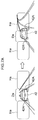
- FIG. 2 is a schematic perspective view illustrating a vehicle front headlight device according to an exemplary embodiment
- FIG. 3 is an explanatory diagram illustrating a sequence of illuminated regions at predetermined different points in time when a rotating mirror undergoes one revolution in a vehicle front headlight device according to an exemplary embodiment
- FIG. 4 is an explanatory diagram illustrating a high beam light distribution area formed by a rotating mirror of a vehicle front headlight device according to an exemplary embodiment
- FIG. 5 is an explanatory diagram illustrating staggered timings for switching a light source on and staggered timings for switching the light source off toward a high beam light distribution area formed by a rotating mirror of a vehicle front headlight device according to an exemplary embodiment.
- FIG. 6 is an explanatory diagram illustrating an illumination intensity of light illuminated in the vicinity of both ends in a vehicle width direction of a leading vehicle by a vehicle front headlight device according to an exemplary embodiment
- FIG. 7A is an explanatory diagram illustrating a high beam light distribution area of a vehicle front headlight device according to a comparative example when a leading vehicle transitions from traveling in straight line to traveling around a curve;
- FIG. 7B is an explanatory diagram illustrating a high beam light distribution area of a vehicle front headlight device according to a comparative example in which a margin is provided at both sides in a vehicle width direction of a leading vehicle.
- arrow UP indicates a vehicle upward direction
- arrow FR indicates a vehicle forward direction
- arrow RH indicates a vehicle right direction, as appropriate.
- reference to up, down, front, rear, left, and right directions refers to up and down in a vehicle vertical direction, front and rear in a vehicle front-rear direction, and left and right in a vehicle left-right direction (vehicle width direction).
- a vehicle 12 is provided with a pair of left and right headlamp units 14 to secure the field of view ahead of the vehicle 12 .
- a headlamp unit 14 R is disposed on the right of a front end section of the vehicle 12
- a headlamp unit 14 L is disposed on the left of the front end section of the vehicle 12 .
- the headlamp units 14 R, 14 L are configured with left-right symmetry to each other in the vehicle width direction, and are each configured including a low beam unit 16 disposed at a vehicle width direction outer side, and a high beam unit 18 disposed at a vehicle width direction inner side.
- the low beam units 16 each illuminates visible light through a lens (not illustrated in the drawings) onto a low beam light distribution area (not illustrated in the drawings) on the road (road surface) ahead of the vehicle 12 .
- the high beam units 18 each illuminates visible light through a lens 32 , described later, onto a high beam light distribution area Ha (see FIG. 4 , FIG. 5 , etc.) higher up and further ahead than the low beam light distribution area illuminated by the low beam units 16 .
- a vehicle front headlight device 10 according to respective exemplary embodiments is applied to the high beam units 18 .
- the high beam units 18 applied with the vehicle front headlight device 10 each includes a light source 20 that emits visible light, a rotating mirror 30 that reflects the visible light emitted from the light source 20 , and a single lens 32 that transmits the visible light reflected by the rotating mirror 30 and illuminates (projects) the visible light ahead (to the exterior of) the vehicle 12 .
- the light source 20 is configured by plural (for example, eight) light emitting diodes (LEDs) arranged on a substrate 22 so as to form a single row with no gaps present between the LEDs.
- the substrate 22 is disposed on a heat sink 24 (see FIGS. 3 and FIG. 4 ).
- the light source 20 (the respective LEDs) is electrically connected to a controller 40 (see FIG. 1 ), and the light source 20 is switched off and on not only by switch operation by a driver, but also under the control of the controller 40 .
- a front surface of the lens 32 is configured by a projecting semispherical curved surface 32 A.
- a rear surface of the lens 32 is configured by a flat surface 32 B. Visible light that has been reflected by the rotating mirror 30 and incident to the rear surface (flat surface 32 B) of the lens 32 passes through the lens 32 and is radiated ahead of the vehicle from the front surface (curved surface 32 A) of the lens 32 . In the interests of simplicity, diffraction of the light by the lens 32 is not illustrated in FIGS. 3 and FIG. 4 .
- the rear surface of the lens 32 is not limited to the flat surface 32 B.
- the rotating mirror 30 is configured by plural mirror bodies 28 (for example, two substantially semicircular mirror bodies 28 as viewed along an axial direction of a shaft 26 ) inclined at a predetermined angle (for example, an angle of 45°) with respect to the axial direction of the shaft 26 , and disposed at uniform intervals around a circumferential direction of the shaft 26 .
- the rotating mirror 30 is capable of being rotationally driven in one direction about the shaft 26 .
- the rotating mirror 30 has a fan-like structure in which the shaft 26 is rotationally driven in the one direction by a motor 27 .
- the motor 27 is electrically connected to the controller 40 , and the rotating mirror 30 is rotationally driven under the control of the controller 40 .
- an illuminated region Ha 1 is formed by reflected light that is a visible light emitted from the light source 20 and reflected by the mirror bodies 28 when allocated at a predetermined first stationary position, for example.
- the illuminated region Ha 1 has a rectangular shape with its length direction in the vertical direction, and is formed at a predetermined position at a left end ahead of the vehicle 12 .
- an illuminated region Ha 2 is formed by reflected light that is light emitted from the light source 20 and reflected by the mirror bodies 28 when allocated at a second stationary position in a state rotated by for example 72° from the first stationary position.
- the illuminated region Ha 2 has a rectangular shape with its length direction in the vertical direction, and is formed at a position shifted toward a center from the predetermined position at the left end ahead of the vehicle 12 .
- the light source 20 is switched off and light is not illuminated by the mirror bodies 28 when allocated at a third stationary position in a state rotated by a further 72° from the second stationary position (144° from the first stationary position).
- a dark area Da is thereby formed as a shaded region where light is not illuminated in the high beam light distribution area Ha.
- an illuminated region Ha 3 is formed by reflected light that is light emitted from the light source 20 and reflected by the mirror bodies 28 when allocated at a fourth stationary position in a state rotated by a further 72° from the third stationary position (216° from the first stationary position).
- the illuminated region Ha 3 has a rectangular shape with its length direction in the vertical direction, and is formed at a position shifted toward a right end from the central position ahead of the vehicle 12 .
- an illuminated region Ha 4 is formed by reflected light that is light emitted from the light source 20 and reflected by the mirror bodies 28 when allocated at a fifth stationary position in a state rotated by a further 72° from the fourth stationary position (288° from the first stationary position).
- the illuminated region Ha 4 has a rectangular shape with its length direction in the vertical direction, and is formed at a predetermined position at the right end ahead of the vehicle 12 .
- the mirror bodies 28 When the mirror bodies 28 are rotated by a further 72° from the fifth stationary position (360° from the first stationary position), the mirror bodies 28 return to the first stationary position and stop.
- the illuminated region formed by light reflected by the mirror bodies 28 in this state is therefore the same as that illustrated in (A) of FIG. 3 . Namely, over a single revolution of the rotating mirror 30 , a rectangular shaped illuminated region with its length direction in the vertical direction is shifted as Ha 1 , Ha 2 , Ha 3 , and Ha 4 along the vehicle width direction from one end to the other end (from the left to the right).
- the high beam light distribution area Ha appears as a substantially rectangular shape with its length direction in the vehicle width direction and with only a substantially central portion in the vehicle width direction not illuminated (the dark area Da only formed at the substantially central portion in the vehicle width direction), due to the afterimage effect of the light.
- the controller 40 controls so as to change the timing at which the light source 20 is switched off and to change the timing at which the light source 20 is switched on at each revolution (each cycle) of the rotating mirror 30 .
- the high beam is illuminated as far as positions very close to the both ends 42 A in the vehicle width direction (imaginary lines K) of the leading vehicle 42 traveling ahead, namely positions separated from the ends 42 A by a narrow width ⁇ 1 to the vehicle width direction outer side from the ends 42 A of the leading vehicle 42 .
- the timing to switch off and the timing to switch on the light source 20 are thus controlled to produce a minimum width dark area Da 1 .
- the high beam is illuminated as far as positions separated from the ends 42 A (imaginary lines K) by a predetermined width ⁇ 2 to the vehicle width direction outer side from the both ends 42 A of the leading vehicle 42 .
- the timing to switch off and the timing to switch on the light source 20 are thus controlled to produce a maximum width dark area Da 2 .
- the timing at which the light source 20 is switched off during the second revolution of the rotating mirror 30 is earlier than the timing at which the light source 20 is switched off during the first revolution (for example the light source 20 is switched off at the timing at which the rotation angle of the mirror body 28 is 1° smaller than during the first revolution).
- the timing at which the light source 20 is switched on during the second revolution of the rotating mirror 30 is later than the timing at which the light source 20 is switched on during the first revolution (for example the light source 20 is switched on at the timing at which the rotation angle of the mirror body 28 is 1° greater than during the first revolution).
- the high beam is illuminated as far as positions separated from the ends 42 A (imaginary lines K) by a width ⁇ 3 to the vehicle width direction outer side from the both ends 42 A of the leading vehicle 42 .
- the width ⁇ 3 is greater than the width ⁇ 1 and smaller than the width ⁇ 2 .
- the timing to switch off and the timing to switch on the light source 20 are thus controlled so as to produce a dark area Da 3 with a width size that is partway between the dark area Da 1 and the dark area Da 2 .
- the timing at which the light source 20 is switched off during the third revolution of the rotating mirror 30 is later than the timing at which the light source 20 is switched off during the second revolution and earlier than the timing at which the light source 20 is switched off during the first revolution (for example the light source 20 is switched off at a timing when the rotation angle of the mirror body 28 is 0.5° smaller than during the first revolution), so as to be a timing that is partway between the timing at which the light source 20 is switched off during the first revolution and the timing at which the light source 20 is switched off during the second revolution.
- the timing at which the light source 20 is switched on during the third revolution of the rotating mirror 30 is later than the timing at which the light source 20 is switched on during the first revolution and earlier than the timing at which the light source 20 is switched on during the second revolution (for example the light source 20 is switched on at a timing when the rotation angle of the mirror body 28 is 0.5° greater than during the first revolution), so as to be a timing that is partway between the timing at which the light source 20 is switched on during the first revolution and the timing at which the light source 20 is switched on during the second revolution.
- the timing at which the light source 20 is switched off and the timing at which the light source 20 is switched on are controlled similarly to during the first revolution of the rotating mirror 30 .
- the timing at which the light source 20 is switched off and the timing at which the light source 20 is switched on are controlled similarly to during the second revolution of the rotating mirror 30 .
- the timing at which the light source 20 is switched off and the timing at which the light source 20 is switched on are controlled similarly to during the third revolution of the rotating mirror 30 .
- the illumination intensity of the light illuminated in the vicinity of the both ends 42 A in the vehicle width direction of the leading vehicle 42 is lower than the illumination intensity of the light illuminated further toward the vehicle width direction outer side. Namely, low illumination intensity areas La where the illumination intensity is low enough not to dazzle a person are formed in the vicinity of the both ends 42 A in the vehicle width direction of the leading vehicle 42 (on both sides of the dark area Da that is ultimately formed).
- illumination intensity distribution in the low illumination intensity areas La is illustrated by solid lines.
- the illumination intensity distribution in the low illumination intensity areas La formed by the vehicle front headlight device 10 according to the present exemplary embodiment is an illumination intensity distribution that is substantially midway between an illumination intensity distribution (illustrated by dashed lines) when light is illuminated as far as the both ends 42 A in the vehicle width direction of the leading vehicle 42 , and an illumination intensity distribution (illustrated by single-dotted dashed lines) when light is only illuminated as far as positions separated from the ends 42 A by a predetermined width toward the vehicle width direction outer side from the both ends 42 A of the leading vehicle 42 .
- the “vicinity of the both ends 42 A in the vehicle width direction of the leading vehicle 42 ” refers to a range of no greater than 1 meter toward the vehicle width direction outer side from the ends 42 A, for example.
- the leading vehicle 42 is recognized by a recognition unit 34 (see FIG. 1 ) configured by a camera, sensor, or the like that is electrically connected to the controller 40 .
- the controller 40 adjusts so as to change the timing at which the light source 20 is switched off and the timing at which the light source 20 is switched on (a width of the dark areas Da) according to a distance to the leading vehicle 42 (the position of the leading vehicle 42 relative to the vehicle 12 ) recognized by the recognition unit 34 .
- the controller 40 also adjusts so as to change the timing at which the light source 20 is switched off and the timing at which the light source 20 is switched on (a width of the dark areas Da) according to a route found using a car navigation system 36 (see FIG. 1 ) (for example according to the number of curves), and weather information (weather conditions such as fine weather or wet weather) detected by a surrounding environment detection device 38 (see FIG. 1 ) including a weather sensor and the like.
- the driver operates a switch to drive rotation of the rotating mirror 30 and switch on the light source 20 , or the controller 40 drives rotation of the rotating mirror 30 and switches on the light source 20 based on, for example, position information recognized by the recognition unit 34 , route information found by the car navigation system 36 , or weather information detected by the surrounding environment detection device 38 provided to the vehicle 12 .
- the dark area Da in which the high beam is not illuminated onto the leading vehicle 42 is set such that the driver and so on of the leading vehicle 42 traveling ahead are not dazzled.
- the timing at which the light source 20 is switched off and the timing at which the light source 20 is switched on are controlled by the controller 40 such that the light source 20 is temporarily switched off in the vicinity of the third stationary position of the rotating mirror 30 .
- the dark area Da were to be set with a narrow width and the high beam were to be illuminated as far as both ends 42 A in a vehicle width direction of the leading vehicle 42 when traveling along a straight road, when the leading vehicle 42 travels around a curve, part of the high beam would fall on the leading vehicle 42 , which could dazzle the driver and so on of the leading vehicle 42 .
- a width of the dark area Da were set wider as in the comparative example illustrated in FIG. 7B , such that the high beam were only illuminated as far as positions separated from the ends 42 A by a predetermined width W to a vehicle width direction outer side from the ends 42 A of the leading vehicle 42 (if margins with the width W were provided), this could decrease the ability of the driver of the vehicle 12 to see ahead of the vehicle (including the leading vehicle 42 ).
- the controller 40 controls so as to change the timing at which the light source 20 is switched off and to change the timing at which the light source 20 is switched on at each revolution of the rotating mirror 30 . Accordingly, the illumination intensity of light illuminated in the vicinity of the ends 42 A in the vehicle width direction of the leading vehicle 42 is lower than the illumination intensity of light illuminated further toward the vehicle width direction outer side.
- the illumination intensity of the light illuminated onto the leading vehicle 42 is low, enabling the driver and so on of the leading vehicle 42 to be suppressed from being dazzled.
- the lower illumination intensity light can be illuminated as far as the ends 42 A of the leading vehicle 42 , thereby decreasing or preventing a reduction in the ability of the driver of the vehicle 12 to see ahead of the vehicle.
- the controller 40 controls so as to change the timing at which the light source 20 is switched off and to change the timing at which the light source 20 is switched on at each revolution of the rotating mirror 30 , thereby reducing the illumination intensity of the light illuminated in the vicinity of the both ends 42 A of the leading vehicle 42 appropriately. This thereby decreases or prevents the driver and so on of the leading vehicle 42 from being dazzled, and decreases or prevents a reduction in the ability of the driver of the vehicle 12 to see ahead of the vehicle.
- the controller 40 is capable of adjusting so as to change the timing at which the light source 20 is switched off and the timing at which the light source 20 is switched on (a width of the dark areas Da) whereby a width of the low illumination intensity areas La is adjusted according to the distance to the leading vehicle 42 (the position of the leading vehicle 42 relative to the vehicle 12 ) recognized by the recognition unit 34 .
- the controller 40 is capable of adjusting so as to change the timing at which the light source 20 is switched off and the timing at which the light source 20 is switched on (a width of the dark areas Da) whereby a width of the low illumination intensity areas La is adjusted according to the route found by the car navigation system 36 .
- This thereby enables the driver and so on of the leading vehicle 42 to be more effectively suppressed from being dazzled than in cases in which the width of the low illumination intensity areas La is constant, irrespective of the route of the vehicle 12 .
- the timing at which the light source 20 is switched off is set earlier and the timing at which the light source 20 is switched on is set later overall when turning tight curves (curves having a small radius of curvature) than when turning gentle curves (curves having a large radius of curvature), enabling a width of the low illumination intensity areas La to be made wider.
- This thereby enables the driver and so on of the leading vehicle 42 to be effectively suppressed from being dazzled when traveling around tight curves.
- the controller 40 is also capable of adjusting so as to change the timing at which the light source 20 is switched off and the timing at which the light source 20 is switched on (a width of the dark areas Da) whereby a width of the low illumination intensity areas La is adjusted according to the weather conditions (weather information) detected by the surrounding environment detection device 38 . This thereby decreases or prevents a reduction in the ability of the driver of the vehicle 12 to see ahead of the vehicle more appropriately than in cases in which the width of the low illumination intensity areas La is constant, irrespective of the weather conditions.
- the timing at which the light source 20 is switched off is set later and the timing at which the light source 20 is switched on is set earlier overall than in fine weather, enabling a width of the low illumination intensity areas La to be made narrower. This thereby decreases or prevents a reduction in the ability of the driver of the vehicle 12 to see ahead of the vehicle appropriately. Namely, the field of view of the driver of the vehicle 12 ahead of the vehicle can be well-secured, even in wet weather.
- the vehicle front headlight device 10 has been explained above with reference to the drawings.
- the vehicle front headlight device 10 according to the present exemplary embodiment is not limited to that illustrated in the drawings, and various design modifications may be implemented within a range not departing from the scope of the present disclosure.
- a width of the Dark areas Da may be set to a constant preset width (without being adjusted for weather conditions and so on).
- the number of the mirror bodies 28 is not limited to two, and there is no limitation to angling the mirror bodies 28 to 45° with respect to the shaft 26 .
- the rotation angle of the rotating mirror 30 used to shift rectangular shaped illuminated regions is set as appropriate according to the number of the mirror bodies 28 and the angle of the mirror bodies 28 with respect to the shaft 26 .
- the vehicle front headlight device 10 according to the present exemplary embodiment may be provided at a headlamp unit 14 provided separately to the high beam unit 18 and the low beam unit 16 .
Landscapes
- Engineering & Computer Science (AREA)
- Physics & Mathematics (AREA)
- General Engineering & Computer Science (AREA)
- Mechanical Engineering (AREA)
- General Physics & Mathematics (AREA)
- Optics & Photonics (AREA)
- Microelectronics & Electronic Packaging (AREA)
- Multimedia (AREA)
- Theoretical Computer Science (AREA)
- Lighting Device Outwards From Vehicle And Optical Signal (AREA)
- Arrangement Of Elements, Cooling, Sealing, Or The Like Of Lighting Devices (AREA)
Abstract
Description
Claims (7)
Applications Claiming Priority (2)
| Application Number | Priority Date | Filing Date | Title |
|---|---|---|---|
| JP2018096044A JP7025282B2 (en) | 2018-05-18 | 2018-05-18 | Vehicle headlight device |
| JP2018-096044 | 2018-05-18 |
Publications (2)
| Publication Number | Publication Date |
|---|---|
| US20190351816A1 US20190351816A1 (en) | 2019-11-21 |
| US10787113B2 true US10787113B2 (en) | 2020-09-29 |
Family
ID=66476459
Family Applications (1)
| Application Number | Title | Priority Date | Filing Date |
|---|---|---|---|
| US16/372,825 Expired - Fee Related US10787113B2 (en) | 2018-05-18 | 2019-04-02 | Vehicle front headlight device |
Country Status (4)
| Country | Link |
|---|---|
| US (1) | US10787113B2 (en) |
| EP (1) | EP3569445A1 (en) |
| JP (1) | JP7025282B2 (en) |
| CN (1) | CN110566899B (en) |
Families Citing this family (7)
| Publication number | Priority date | Publication date | Assignee | Title |
|---|---|---|---|---|
| CN111810916A (en) * | 2020-08-05 | 2020-10-23 | 摩登汽车(盐城)有限公司 | Automobile illumination adjusting device |
| CN112902105B (en) * | 2021-03-25 | 2022-09-30 | 兰普电器股份有限公司 | Special-shaped side reflection headlamp |
| JP7515768B2 (en) * | 2022-03-31 | 2024-07-12 | 三菱電機株式会社 | Vehicle light distribution control device and vehicle light distribution control method |
| KR20230168859A (en) * | 2022-06-08 | 2023-12-15 | 현대모비스 주식회사 | Vehicle lighting device and method of operating thereof |
| JP7736638B2 (en) * | 2022-06-30 | 2025-09-09 | スタンレー電気株式会社 | Vehicle lighting system |
| CN119546484A (en) * | 2022-07-27 | 2025-02-28 | 株式会社小糸制作所 | Vehicle headlights |
| JP2024135833A (en) * | 2023-03-23 | 2024-10-04 | トヨタ自動車株式会社 | Vehicle Lighting System |
Citations (9)
| Publication number | Priority date | Publication date | Assignee | Title |
|---|---|---|---|---|
| JPS5722882B2 (en) | 1976-01-06 | 1982-05-15 | ||
| DE10321564A1 (en) | 2003-05-14 | 2004-12-16 | Audi Ag | Vehicle headlamp having a piezo-optical element which affects the optical properties of the light emitting surface |
| US20130038736A1 (en) | 2010-04-13 | 2013-02-14 | Koito Manufacturing Co., Ltd. | Optical unit, vehicle monitor, and obstruction detector |
| US20140042325A1 (en) * | 2011-04-22 | 2014-02-13 | Koito Manufacturing Co., Ltd. | Obstacle detecting device |
| EP3061653A1 (en) | 2015-02-27 | 2016-08-31 | Toyota Jidosha Kabushiki Kaisha | Vehicle headlight control device |
| DE102017218777A1 (en) | 2016-10-24 | 2018-04-26 | Koito Manufacturing Co., Ltd. | Optical unit |
| US20180290583A1 (en) * | 2017-04-10 | 2018-10-11 | Lg Electronics Inc. | Vehicle control method |
| US20180332680A1 (en) * | 2017-05-11 | 2018-11-15 | Koito Manufacturing Co., Ltd. | Drive circuit and vehicle lamp |
| US20180372303A1 (en) * | 2017-06-22 | 2018-12-27 | Lg Electronics Inc. | Lamp For Vehicle And Method For Controlling The Same |
Family Cites Families (8)
| Publication number | Priority date | Publication date | Assignee | Title |
|---|---|---|---|---|
| DE102008038536A1 (en) * | 2008-08-20 | 2010-02-25 | Hella Kgaa Hueck & Co. | Method and device for controlling the vertical cut-off for headlamps |
| DE102012224345A1 (en) * | 2012-12-21 | 2014-06-26 | Osram Gmbh | Vehicle lighting device |
| JP6166225B2 (en) * | 2014-06-10 | 2017-07-19 | トヨタ自動車株式会社 | Vehicle headlamp control device |
| EP3216650A4 (en) * | 2014-11-07 | 2018-06-13 | Dai Nippon Printing Co., Ltd. | Lighting device |
| WO2016208628A1 (en) * | 2015-06-22 | 2016-12-29 | 大日本印刷株式会社 | Illumination apparatus |
| JP6352892B2 (en) * | 2015-12-08 | 2018-07-04 | トヨタ自動車株式会社 | Vehicle headlamp structure and vehicle headlamp control method |
| CN106500039A (en) * | 2016-11-04 | 2017-03-15 | 武汉通畅汽车电子照明有限公司 | A kind of high-resolution headlight for vehicles optics module and its high-resolution far lighting control method |
| EP3936385A1 (en) * | 2017-10-13 | 2022-01-12 | Koito Manufacturing Co., Ltd. | Vehicle lamp |
-
2018
- 2018-05-18 JP JP2018096044A patent/JP7025282B2/en not_active Expired - Fee Related
-
2019
- 2019-04-01 CN CN201910257256.3A patent/CN110566899B/en not_active Expired - Fee Related
- 2019-04-02 US US16/372,825 patent/US10787113B2/en not_active Expired - Fee Related
- 2019-05-09 EP EP19173446.6A patent/EP3569445A1/en not_active Withdrawn
Patent Citations (14)
| Publication number | Priority date | Publication date | Assignee | Title |
|---|---|---|---|---|
| JPS5722882B2 (en) | 1976-01-06 | 1982-05-15 | ||
| DE10321564A1 (en) | 2003-05-14 | 2004-12-16 | Audi Ag | Vehicle headlamp having a piezo-optical element which affects the optical properties of the light emitting surface |
| US20170159904A1 (en) | 2010-04-13 | 2017-06-08 | Koito Manufacturing Co., Ltd. | Optical Unit, Vehicle Monitor, and Obstruction Detector |
| US20130038736A1 (en) | 2010-04-13 | 2013-02-14 | Koito Manufacturing Co., Ltd. | Optical unit, vehicle monitor, and obstruction detector |
| JP5722882B2 (en) | 2010-04-13 | 2015-05-27 | 株式会社小糸製作所 | Optical unit |
| US20170185855A1 (en) | 2010-04-13 | 2017-06-29 | Koito Manufacturing Co., Ltd. | Optical Unit, Vehicle Monitor, and Obstruction Detector |
| US20170159903A1 (en) | 2010-04-13 | 2017-06-08 | Koito Manufacturing Co., Ltd. | Optical Unit, Vehicle Monitor, and Obstruction Detector |
| US20140042325A1 (en) * | 2011-04-22 | 2014-02-13 | Koito Manufacturing Co., Ltd. | Obstacle detecting device |
| EP3061653A1 (en) | 2015-02-27 | 2016-08-31 | Toyota Jidosha Kabushiki Kaisha | Vehicle headlight control device |
| DE102017218777A1 (en) | 2016-10-24 | 2018-04-26 | Koito Manufacturing Co., Ltd. | Optical unit |
| US20180112845A1 (en) | 2016-10-24 | 2018-04-26 | Koito Manufacturing Co., Ltd. | Optical unit |
| US20180290583A1 (en) * | 2017-04-10 | 2018-10-11 | Lg Electronics Inc. | Vehicle control method |
| US20180332680A1 (en) * | 2017-05-11 | 2018-11-15 | Koito Manufacturing Co., Ltd. | Drive circuit and vehicle lamp |
| US20180372303A1 (en) * | 2017-06-22 | 2018-12-27 | Lg Electronics Inc. | Lamp For Vehicle And Method For Controlling The Same |
Also Published As
| Publication number | Publication date |
|---|---|
| JP2019199224A (en) | 2019-11-21 |
| CN110566899B (en) | 2022-04-19 |
| JP7025282B2 (en) | 2022-02-24 |
| CN110566899A (en) | 2019-12-13 |
| EP3569445A1 (en) | 2019-11-20 |
| US20190351816A1 (en) | 2019-11-21 |
Similar Documents
| Publication | Publication Date | Title |
|---|---|---|
| US10787113B2 (en) | Vehicle front headlight device | |
| JP7186713B2 (en) | vehicle lamp | |
| EP2551155B1 (en) | Light distribution controller of headlamp | |
| US10670216B2 (en) | Vehicle lamp including rotary reflector | |
| EP3483498B1 (en) | Vehicle headlight device | |
| JP7057674B2 (en) | Headlight device | |
| CN104235720B (en) | Headlamp for a motor vehicle comprising a laser light source | |
| CN108349426B (en) | Lighting systems for motor vehicles | |
| US20140218946A1 (en) | Short-Range Cornering Light in an Exterior Mirror | |
| US20180112845A1 (en) | Optical unit | |
| JP2017030735A (en) | System and method for controlling light beam and corresponding lighting and/or signaling module | |
| CN107606579B (en) | Vehicle lamp | |
| JP7688765B2 (en) | Vehicle lighting device and vehicle system | |
| US20200164793A1 (en) | Vehicle front headlight device | |
| US10471886B1 (en) | Vehicle front headlight device | |
| JP7315111B2 (en) | variable light distribution system | |
| CN114954208B (en) | Vehicle lighting device | |
| JP7559661B2 (en) | Vehicle lighting device control apparatus and vehicle lighting device | |
| JP7127492B2 (en) | Vehicle headlight device | |
| JP6966335B2 (en) | Vehicle lighting | |
| WO2025234100A1 (en) | Headlight control device | |
| WO2025083851A1 (en) | Headlight control device | |
| JP6203541B2 (en) | Rear fog lamp device | |
| CN118613393A (en) | Lighting systems for motor vehicles |
Legal Events
| Date | Code | Title | Description |
|---|---|---|---|
| AS | Assignment |
Owner name: KOITO MANUFACTURING CO., LTD., JAPAN Free format text: ASSIGNMENT OF ASSIGNORS INTEREST;ASSIGNORS:MOURI, FUMIHIKO;HONDA, TAKAHIKO;SIGNING DATES FROM 20190108 TO 20190130;REEL/FRAME:048767/0220 Owner name: TOYOTA JIDOSHA KABUSHIKI KAISHA, JAPAN Free format text: ASSIGNMENT OF ASSIGNORS INTEREST;ASSIGNORS:MOURI, FUMIHIKO;HONDA, TAKAHIKO;SIGNING DATES FROM 20190108 TO 20190130;REEL/FRAME:048767/0220 |
|
| FEPP | Fee payment procedure |
Free format text: ENTITY STATUS SET TO UNDISCOUNTED (ORIGINAL EVENT CODE: BIG.); ENTITY STATUS OF PATENT OWNER: LARGE ENTITY |
|
| STPP | Information on status: patent application and granting procedure in general |
Free format text: NON FINAL ACTION MAILED |
|
| STPP | Information on status: patent application and granting procedure in general |
Free format text: NOTICE OF ALLOWANCE MAILED -- APPLICATION RECEIVED IN OFFICE OF PUBLICATIONS |
|
| STCF | Information on status: patent grant |
Free format text: PATENTED CASE |
|
| FEPP | Fee payment procedure |
Free format text: MAINTENANCE FEE REMINDER MAILED (ORIGINAL EVENT CODE: REM.); ENTITY STATUS OF PATENT OWNER: LARGE ENTITY |
|
| LAPS | Lapse for failure to pay maintenance fees |
Free format text: PATENT EXPIRED FOR FAILURE TO PAY MAINTENANCE FEES (ORIGINAL EVENT CODE: EXP.); ENTITY STATUS OF PATENT OWNER: LARGE ENTITY |
|
| STCH | Information on status: patent discontinuation |
Free format text: PATENT EXPIRED DUE TO NONPAYMENT OF MAINTENANCE FEES UNDER 37 CFR 1.362 |
|
| FP | Lapsed due to failure to pay maintenance fee |
Effective date: 20240929 |