US10777396B2 - Differential electrochemical mass spectrometry (DEMS) cell - Google Patents
Differential electrochemical mass spectrometry (DEMS) cell Download PDFInfo
- Publication number
- US10777396B2 US10777396B2 US14/944,085 US201514944085A US10777396B2 US 10777396 B2 US10777396 B2 US 10777396B2 US 201514944085 A US201514944085 A US 201514944085A US 10777396 B2 US10777396 B2 US 10777396B2
- Authority
- US
- United States
- Prior art keywords
- cell
- dems
- chamber
- working electrode
- catholyte
- Prior art date
- Legal status (The legal status is an assumption and is not a legal conclusion. Google has not performed a legal analysis and makes no representation as to the accuracy of the status listed.)
- Active
Links
Images


Classifications
-
- H—ELECTRICITY
- H01—ELECTRIC ELEMENTS
- H01J—ELECTRIC DISCHARGE TUBES OR DISCHARGE LAMPS
- H01J49/00—Particle spectrometers or separator tubes
- H01J49/0009—Calibration of the apparatus
-
- G—PHYSICS
- G01—MEASURING; TESTING
- G01N—INVESTIGATING OR ANALYSING MATERIALS BY DETERMINING THEIR CHEMICAL OR PHYSICAL PROPERTIES
- G01N27/00—Investigating or analysing materials by the use of electric, electrochemical, or magnetic means
- G01N27/26—Investigating or analysing materials by the use of electric, electrochemical, or magnetic means by investigating electrochemical variables; by using electrolysis or electrophoresis
- G01N27/28—Electrolytic cell components
-
- H—ELECTRICITY
- H01—ELECTRIC ELEMENTS
- H01J—ELECTRIC DISCHARGE TUBES OR DISCHARGE LAMPS
- H01J49/00—Particle spectrometers or separator tubes
- H01J49/004—Combinations of spectrometers, tandem spectrometers, e.g. MS/MS, MSn
- H01J49/009—Spectrometers having multiple channels, parallel analysis
-
- H—ELECTRICITY
- H01—ELECTRIC ELEMENTS
- H01J—ELECTRIC DISCHARGE TUBES OR DISCHARGE LAMPS
- H01J49/00—Particle spectrometers or separator tubes
- H01J49/02—Details
- H01J49/06—Electron- or ion-optical arrangements
- H01J49/062—Ion guides
- H01J49/065—Ion guides having stacked electrodes, e.g. ring stack, plate stack
-
- H—ELECTRICITY
- H01—ELECTRIC ELEMENTS
- H01J—ELECTRIC DISCHARGE TUBES OR DISCHARGE LAMPS
- H01J49/00—Particle spectrometers or separator tubes
- H01J49/02—Details
- H01J49/10—Ion sources; Ion guns
- H01J49/14—Ion sources; Ion guns using particle bombardment, e.g. ionisation chambers
Definitions
- the present invention is in the field of differential electrochemical mass spectrometry (DEMS).
- DEMS differential electrochemical mass spectrometry
- the electrochemical CO 2 reduction reaction (CO 2 RR) is a subject of considerable current interest that is motivated by the desire to develop methods for converting atmospheric CO 2 to fuels using electrical energy generated from renewable sources such as wind and solar power.
- commercial implementation of the CO 2 RR has yet to be realized, primarily due to challenges associated with electrocatalyst activity and selectivity.
- the reaction requires approximately 800 mV of overpotential to produce hydrocarbons and alcohols (Hori, Y., Takahashi, R., Yoshinami, Y. & Murata, A. Electrochemical Reduction of CO at a Copper Electrode. J. Phys. Chem. C 101, 7075-7081 (1997); Durand, W. J., Peterson, A.
- DEMS Differential electrochemical mass spectrometry
- the activity and selectivity of a given electrocatalyst can be studied in real time as a function of the applied potential. This ultimately enables the potential dependence and transient nature of the reaction selectivity to be rapidly screened.
- the electrodes should be spatially separated by either a proton or anion-conducting membrane. If the electrodes are not spatially separated, it is possible that Faradaic current from oxygen reduction can occur while studying CO 2 RR electrocatalysts. The amount of Faradaic current from this unwanted reaction cannot be quantified since the only product is water. In the absence of spatial separation of the electrodes, products formed at the cathode can undergo oxidation at the anode thereby reducing the concentration of products that can be detected. Yet another design constraint is that the cross sectional area of electrolyte between the working and counter electrodes should be large.
- the first DEMS cell to use electrolyte flow was the thin-layer flow cell (Hartung, T. & Baltruschat, H. Differential Electrochemical Mass Spectrometry Using Smooth Electrodes: Adsorption and H/D-Exchange Reactions of Benzene on Pt. Langmuir 6, 953-957 (1990)).
- This cell geometry consisted of a thin layer of electrolyte, approximately 100 microns thick, that separated the working electrode and the pervaporation membrane.
- This cell geometry suffers from a low product collection efficiency because products generated near the electrolyte outlet are swept out of the chamber before mass transport to the pervaporation membrane can occur. Furthermore, the non-parallel electrode configuration makes it impossible to study the reaction selectivity. To solve the issues of low product collection efficiency the dual thin-layer flow cell was developed (Jusys, Z., Kaiser, J. & Behm, R. J. A novel dual thin-layer flow cell double-disk electrode design for kinetic studies on supported catalysts under controlled mass-transport conditions. Electrochim. Acta 49, 1297-1305 (2004)). This cell geometry locates the working electrode and the pervaporation membrane in separate chambers, connected by four transfer capillaries.
- the present invention provides for a differential electrochemical mass spectrometry (DEMS) cell comprising a working electrode chamber and a working electrode configured such that an electrolyte enters the working electrode chamber through a channel running through the working electrode.
- DEMS differential electrochemical mass spectrometry
- the working electrode comprises a washer-shape and the channel is at the center of the washer-shaped working electrode.
- the DEMS cell comprises a first electrolyte inlet in fluid communication with a first electrode chamber which is in turn in fluid communication with and a first electrolyte outlet, a second electrolyte inlet in fluid communication with a second electrode chamber which is in turn in fluid communication with and a second electrolyte outlet, a first electrode comprising a first surface exposed to the first electrode chamber, a second electrode comprising a second surface exposed to the second electrode chamber, and a first membrane transposed between the first electrode chamber and the second electrode chamber, wherein the first electrode chamber is a working electrode chamber configured such that the first electrolyte enters the working electrode chamber through a channel running through the first electrode, or the second electrode chamber is a working electrode chamber configured such that the second electrolyte enters the working electrode chamber through a channel running through the second electrode.
- the first electrolyte flows from an outside source of the first electrolyte into the DEMS cell in a direction from the first electrolyte inlet to the first electrode chamber to the first electrolyte outlet, and then out of the DEMS cell.
- the second electrolyte flows from an outside source of the second electrolyte into the DEMS cell in a direction from the second electrolyte inlet to the second electrode chamber to the second electrolyte outlet, and then out of the DEMS cell.
- the DEMS cell comprises the structure shown in FIG. 1A .
- 1 is the first electrolyte inlet
- 2 is the first electrode chamber
- 3 is the first electrolyte outlet
- 4 is the second electrolyte inlet
- 5 is the second electrode chamber
- 6 is the second electrolyte outlet
- 7 is the second electrode
- 8 is the first electrode
- 9 is the first membrane
- 10 is the second membrane
- 11 is a stainless steel frit
- 12 is the body (of the DEMS cell)
- 13 is a third chamber
- 14 is the direction of flow of the first electrolyte into the DEMS cell
- 15 is the direction of flow of the first electrolyte out of the DEMS cell
- 16 is the direction of flow of the second electrolyte into the DEMS cell
- 17 is the direction of flow of the second electrolyte out of the DEMS cell
- 18 is a transfer capillary
- 19 is the first surface of the first electrode exposed to the first electrode chamber
- 20 is the second surface of the
- the stainless steel frit 11 is porous to water. During the operation of the DEMS cell, the flow of fluid from channel 21 through the second electrode chamber 5 to the transfer capillary 18 is able to sweep away bubbles that form on second surface 20 of the second electrode exposed to the second electrode chamber.
- the second membrane 10 is hydrophobic and blocks movement of water molecules but permits movement of gas through the second membrane 10 .
- the first electrolyte is an anolyte and the first electrode is an anode
- the second electrolyte is a catholyte and the second electrode is a cathode
- the working electrode chamber is the cathode chamber
- the working electrode is the cathode.
- the anode is a platinum anode, or Pt black anode.
- the cathode is a copper cathode.
- the first membrane is an ion-conducting membrane, such as an anion-conducting membrane.
- the second membrane is a pervaporation membrane.
- the second electrode is the working electrode, and/or the second electrolyte chamber is the working electrode chamber.
- the DEMS cell comprises the structure shown in FIG. 1B .
- This DEMS cell is identical to the DEMS cell shown in FIG. 1A except that it further comprises of three structures: 22 is a hollow screw that fixes second electrode 7 to the body 12 of the DEMS cell.
- the hollow screw 22 has a channel 21 running through the hollow screw 22 and also through the second electrode 7 or working electrode.
- 23 is a reference electrode which is located at the angle formed between channel 21 and second electrolyte inlet 4 , or the base of hollow screw 22 .
- 24 is a gold pin which makes electrical contact between second electrode 7 and a means of electrical communication to the outside of the DEMS cell, such as an electrical wire.
- the DEMS cell further comprises one or more other features described herein and/or in FIG. 1A, 1B, 1C , or 1 D.
- the second surface is about 0.5 cm 2 to about 2 cm 2 . In some embodiments, the second surface is about 0.75 cm 2 to about 1.5 cm 2 . In some embodiments, the second surface is about 0.9 cm 2 to about 1.1 cm 2 . In some embodiments, the second surface is about 1 cm 2 . In some embodiments, the washer-shaped working electrode comprises an exposed surface area of about 0.5 cm 2 to about 2 cm 2 . In some embodiments, the washer-shaped working electrode comprises an exposed surface area of about 0.75 cm 2 to about 1.5 cm 2 . In some embodiments, the washer-shaped working electrode comprises an exposed surface area of about 0.9 cm 2 to about 1.1 cm 2 . In some embodiments, the washer-shaped working electrode comprises an exposed surface area of about 1 cm 2 .
- the total volume of the working electrode chamber is less than about 40 ⁇ L. In some embodiments, the total volume of the working electrode chamber is less than about 30 ⁇ L. In some embodiments, the total volume of the working electrode chamber is less than about 20 ⁇ L. In some embodiments, the total volume of the working electrode chamber is less than about 15 ⁇ L. In some embodiments, the total volume of the working electrode chamber is less than about 10 ⁇ L.
- the shortest or average distance from the working electrode to the first membrane is at most about 200 ⁇ m, 175 ⁇ m, 150 ⁇ m, 125 ⁇ m, 100 ⁇ m, 75 ⁇ m, 50 ⁇ m, 25 ⁇ m, or 10 ⁇ m, or the shortest or average distance from the working electrode to the first membrane is a distance from about any two of the distances described herein, such as from about 10 ⁇ m to about 200 ⁇ m.
- the DEMS cell has one of the configurations depicted in FIGS. 1A to 1D .
- a novel feature of the DEMS cell is that the DEMS is configured such that an electrolyte enters the working electrode chamber through the center of a washer-shaped working electrode with a suitable exposed surface area, such as 1 cm 2 .
- the electrolyte rapidly reaches the proton or anion-conducting membrane, which is separated from the working electrode by a thin layer of electrolyte 100 microns thick.
- the electrolyte then flows laterally outwards toward the four transfer capillaries.
- the total volume of the working electrode chamber is less than 20 ⁇ L.
- the reference electrode is introduced into the cell through a capillary port and is positioned roughly 1 mm from the working electrode.
- FIG. 2 Details of the working electrode chamber are shown in FIG. 2 .
- a third chamber, housing the counter electrode, is located above the working electrode chamber, ensuring a parallel electrode configuration.
- the surface area of the proton or anion-conducting membrane between the two electrodes is roughly 1.75 cm 2 .
- a novel feature of this design is the washer-shaped working electrode.
- the cell design shown in FIGS. 1A to 1D enables a parallel electrode configuration to be used and ensures attainment of a low transit time from the working electrode chamber to the collection chamber. Initial tests of the cell performance have been extremely promising and are shown in FIGS. 3A to 3G .
- operating the DEMS cell produces results at least equal to or better than the results described herein.
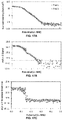
- the hydrogen evolution reaction (HER) data obtained using a copper working electrode is shown in FIGS. 3A and 3B .
- the first plot proves that the DEMS cell geometry does not affect the current-voltage characteristics of the cathode, since the voltammogram obtained in the DEMS cell matches that obtained in a conventional bulk electrolysis cell.
- the bottom plot shows that the ion current for H 2 recorded a mass spectrometer is fully consistent with voltammogram, from which it is deduced that the cell exhibits a 100% Faradaic efficiency for the formation of H 2 .
- the DEMS cell of the present invention can be used in any of the following applications: analyzing the products of the CO 2 RR, and other electrochemical processes, such as the electrochemical synthesis of organic molecules and the electrochemical reforming of an organic solvent/gas (such as methanol) to synthesis gas.
- electrochemical processes such as the electrochemical synthesis of organic molecules and the electrochemical reforming of an organic solvent/gas (such as methanol) to synthesis gas.
- FIG. 1A shows a schematic of an embodiment of the DEMS cell.
- FIG. 1B shows a schematic of another embodiment of the DEMS cell.
- FIG. 1C shows a schematic of a further embodiment of the DEMS cell.
- 100 Mounting Screw Holes.
- 101 Anolyte Inlet.
- 102 Removable Cu Cathode.
- 104 Reference Electrode Port.
- 106 Cathode Receptacle.
- 107 Catholyte Inlet.
- 108 Collection Chamber.
- 109 To MS.
- 110 Anolyte Outlet.
- 111 Anode Chamber.
- 112 Pt Black Anode.
- 114 Anion Conducting Membrane.
- 116 Cathode Chamber.
- 117 Catholyte Outlet.
- 118 Transfer Capillary (1 of 4).
- 120 Teflon Membrane.
- FIG. 1D shows a schematic of an even further embodiment of the DEMS cell.
- 130 Counter Electrode.
- 131 Anolyte Inlet.
- 132 Reference Electrode.
- 134 Cathode Receptacle. 135 : Catholyte Inlet.
- 136 Pervaporation Membrane.
- 138 Stainless Steel Frit.
- 139 To MS.
- 140 Anolyte Outlet.
- 141 Ion-Conducting Membrane.
- 142 Washer Working Electrode.
- 143 Catholyte Outlet.
- 144 Transfer Capillary (1 of 4).
- FIG. 2 shows an embodiment of a working electrode chamber with electrolyte inlets and outlets labeled.
- 202 Electrolyte In.
- 204 Reference Electrode Port.
- 206 Electrolyte Out.
- FIG. 3C shows data obtained with the proposed DEMS cell in both N 2 and CO 2 sparged electrolytes showing current density and m/z mass ion currents corresponding to reaction products of interest obtained in CO 2 sparged 0.1 M KHCO 3 .
- FIG. 3D shows data obtained with the proposed DEMS cell in both N 2 and CO 2 sparged electrolytes showing current density and m/z mass ion currents corresponding to reaction products of interest obtained in CO 2 sparged 0.1 M KHCO 3 .
- FIG. 3E shows data obtained with the proposed DEMS cell in both N 2 and CO 2 sparged electrolytes showing current density and m/z mass ion currents corresponding to reaction products of interest obtained in CO 2 sparged 0.1 M KHCO 3 .
- FIG. 3F shows data obtained with the proposed DEMS cell in both N 2 and CO 2 sparged electrolytes showing current density and m/z mass ion currents corresponding to reaction products of interest obtained in CO 2 sparged 0.1 M KHCO 3 .
- FIG. 3G shows data obtained with the proposed DEMS cell in both N 2 and CO 2 sparged electrolytes showing current density and m/z mass ion currents corresponding to reaction products of interest obtained in CO 2 sparged 0.1 M KHCO 3 .
- FIG. 4A shows the partial current densities of the CO 2 RR products obtained on metallic copper.
- FIG. 4B shows the partial current densities of the CO 2 RR products obtained on metallic copper.
- FIG. 4C shows the partial current densities of the CO 2 RR products obtained on metallic copper.
- FIG. 5A shows a schematic of DEMS cell designs described in the current literature.
- FIG. 5B shows a schematic of DEMS cell designs described in the current literature.
- FIG. 6 shows the residence time distribution in the WE chamber.
- FIG. 7A shows the calculated velocity field across the WE Surface at 1 mL/min.
- FIG. 7B shows the calculated pressure field across the WE Surface at 1 mL/min.
- FIG. 8 shows the liquid product generation rates as a function of potential on polycrystalline copper.
- FIG. 9 shows a Nyquist plot obtained at open circuit potential.
- FIG. 10 shows the RRQRQ equivalent circuit of the DEMS cell.
- FIG. 11 shows the Nyquist plot as a function of applied potential.
- FIG. 12 shows R u increasing as a function of potential.
- FIG. 13 shows a schematic of an embodiment of the DEMS cell.
- 1301 Anolyte Inlet.
- 1302 Washer Working Electrode.
- 1304 Reference Electrode.
- 1305 Catholyte Inlet.
- 1306 Pervaporation Membrane.
- 1307 To MS.
- 1308 Anolyte Outlet.
- 1309 Counter Electrode.
- 1310 Ion-Conducting Membrane.
- 1312 Mounting Screw.
- 1313 Catholyte Outlet.
- 1314 Transfer Capillary (1 of 4).
- 1316 Stainless Steel Frit.
- FIG. 14 shows a photograph of a working electrode chamber.
- FIG. 15A shows a catholyte flow field in the working electrode chamber at a flow rate of 1 mL/min for convection driven by positive pressure applied at the inlet.
- the working electrode surface is denoted by the region between the dashed white lines.
- FIG. 15B shows a catholyte flow field in the working electrode chamber at a flow rate of 1 mL/min for convection driven by negative pressure applied at the outlet.
- the working electrode surface is denoted by the region between the dashed white lines.
- FIG. 16 shows an average residence time and distribution (error bars) of the catholyte in the working electrode chamber as a function of the electrolyte flow rate.
- the electrochemical CO 2 reduction reaction (CO 2 RR) is a subject of considerable current interest that is motivated by the desire to develop methods for converting atmospheric CO 2 into fuels using electrical energy generated from renewable sources 1 .
- Commercial implementation of the CO 2 RR has yet to be realized, primarily due to challenges associated with electrocatalyst activity and selectivity. Copper has been identified as the only metallic electrocatalyst capable of reducing CO 2 to hydrocarbons and alcohols. 2,3
- the reaction requires an overpotential of ⁇ 800 mV, 4-8 resulting in an overall energy conversion efficiency for the CO 2 RR process of ⁇ 20%.
- the reaction can produce up to 16 different products depending on the composition of the electrocatalyst and the applied potential 9 .
- Solvated CO 2 molecules are believed to be the electroactive species since no CO 2 RR products have been detected in electrolyzed solutions of KHCO 3 and K 2 CO 3 in CO 2 -free atmospheres 10 .
- metallic copper reduces CO 2 to both formic acid and carbon monoxide (CO), as shown in FIGS. 4A to 4C .
- the unique ability of copper to catalyze the reduction of CO 2 to hydrocarbons and alcohols has been attributed to the moderate strength of CO adsorption to the copper surface. 4,11-13 Since the same distribution of products are obtained from CO reduction (CORR) and CO 2 RR on metallic copper, 14,15 CO is considered to be an intermediate in the pathway to more reduced products.
- the overpotential determining step in the production of hydrocarbons and alcohols from CO 2 occurs after the formation of CO since the same overpotential is required to produce hydrocarbons and alcohols via CORR. 14,15
- Formic acid has been shown experimentally to be a dead-end intermediate at the potentials relevant to CO 2 RR on metallic copper. 16-21
- the formation rates of methane and ethylene are known to be dictated by different rate-determining steps, as indicated by their differing Tafel slopes and partial current proton concentration dependance. 4
- all C 2+ products are believed to share a common intermediate since their generation rates all follow a common potential dependence, as depicted in FIGS. 4A to 4C .
- DEMS Differential electrochemical mass spectrometry
- the activity and selectivity of a given electrocatalyst can be studied in real time as a function of the applied potential. This ultimately enables the potential dependence and transient nature of the reaction selectivity to be rapidly analyzed.
- the efficacy and capabilities of DEMS strongly depends on the design of the electrochemical cell, which must be capable of achieving both a rapid response time and a high product collection efficiency. 24 As a result, electrochemical cells are specially designed to meet these criteria. However, several additional design criteria must also be met to ensure meaningful product quantification.
- the working (WE) and counter electrodes (CE) should be parallel in order to ensure that the applied potential does not vary as a function of position on the electrode surface. If this design criterion is not met then the partial current of a given product will vary across the electrode surface, making it impossible to make accurate conclusions about the reaction selectivity.
- the electrodes should be spatially separated by an ion-conducting membrane in order to ensure that products formed at the cathode do not undergo oxidation at the anode, thereby reducing the perceived selectivity of a given electrocatalyst. Furthermore, this prevents Faradaic current from O 2 reduction at the WE. Yet another design constraint is that the cross sectional area of electrolyte separating the WE and CE should be large, which will result in a low cell impedance and reduce the propensity of bubble formation to break the electrical continuity between the electrodes.
- the CO 2 RR can become diffusion limited in stagnant electrolytes in less than three minutes at potentials lower than ⁇ 1.1 V vs RHE, electrolyte convection must be employed to study a given electrocatalysts transient selectivity over longer timescales.
- the volume of electrolyte between the WE and the pervaporation membrane should be minimized so that the transit time between them can be reduced. If the cell volume is not minimized then excessively high electrolyte flow rates will have to be employed to attain acceptable transit times, resulting in product dilution and reduced detectability.
- the surface area of the WE should be large so that the concentration of reaction products can be maximized.
- the first DEMS cell to use electrolyte flow was the thin-layer flow cell, depicted in FIGS. 5A and 5B . 25
- This cell geometry consists of a thin layer of electrolyte, approximately 100 ⁇ m thick, separating the WE and the pervaporation membrane. This cell geometry suffers from a low product collection efficiency because products generated near the electrolyte outlet are swept out of the chamber before mass transport to the pervaporation membrane can occur.
- the counter electrode is connected to the outlet capillary, resulting in an extremely high cell resistance.
- This approach employs a capillary tube with a porous Teflon tip, which is brought within 20 microns of the electrode surface in order to sample products formed by the CO 2 RR. While this geometry enables the use of a parallel electrode configuration it also makes product quantification impossible because the collection efficiency is extremely low and highly dependent on the precise orientation of the porous Teflon tip with respect to the electrode surface. Thus, we conclude that the DEMS cell designs described in the literature are not capable of product quantification or detecting the liquid phase products of the CO 2 RR. Therefore, we were motivated to undertake the design and construction of a novel DEMS cell that would enable quantification of products and determination of Faradaic efficiencies in a continuous fashion.
- FIGS. 1A to 1D A schematic of a novel DEMS cell is depicted in FIGS. 1A to 1D .
- the main feature differentiating it from previous designs is that the electrolyte enters the WE chamber through the center of a washer-shaped electrode, which has an exposed surface area of 1 cm 2 .
- the electrolyte rapidly reaches the ion-conducting membrane, which is separated from the WE surface by a thin layer of electrolyte approximately 100 ⁇ m thick.
- the electrolyte then flows laterally outwards towards the four transfer capillaries.
- the unique electrode design enables the total volume of the WE chamber to be less than 20 ⁇ L.
- the reference electrode is introduced through a capillary port and is positioned roughly 1 mm from the surface of the WE.
- the geometry of the WE chamber is shown in FIG.
- a third chamber housing the CE is located above the WE chamber, ensuring a parallel electrode configuration.
- This parallel electrode geometry is only possible due to the unique washer-shaped WE employed in this design.
- the CE is a mesh disc with an exposed surface area of roughly 2 cm 2 .
- the surface area of the ion-conducting membrane separating the two electrodes is roughly 1.75 cm 2 , resulting in a low cell impedance and robust electrode connectivity.
- the DEMS cell was fabricated out of polycarbonate and fitted with nitrile rubber O-rings.
- the WE was machined from a copper rod (99.999%). Prior to each experiment the WE surface was mechanically polished with a diamond polishing compound to a mirror-like finish (0.1 ⁇ m, Ted Pella Inc.).
- the counter electrode was a Pt gauze disc (100 mesh, 99.9% Sigma Aldrich) that was thermally annealed prior to each experiment.
- An Ag/AgCl electrode was used as the reference (1 mm OD, Innovative Instruments Inc.).
- a proton-conducting membrane (Nafion 110, Ion Power Inc.) was used to separate the WE and CE chambers.
- a PTFE sheet (20 nm pore size, Hangzhou Cobetter Filtration Equipment Co.) was used as the pervaporation membrane.
- the electrolyte was drawn from a sparging tank where CO 2 (5.0 Paxair) was bubbled through a 0.1 M KHCO 3 (99.7% Sigma Aldrich) solution prepared using 18.2 M ⁇ deionized water from a Millipore system.
- the steady state pH of the electrolyte was 6.8.
- the transit time from the working electrode chamber to the collection chamber should be less than 1 s.
- the residence time distribution of the electrolyte in the WE chamber and the four transfer capillaries was calculated as a function of flow rate by solving the Navier-Stokes equation in ComSol Multiphysics. The results of this calculation are shown in FIG. 6 , which indicate that an electrolyte flow rate of at least 0.5 mL/min is required to achieve the desired transit time. However, the standard deviation of the residence time distribution is rather large at this flow rate, as indicated by the error bars.
- an electrolyte flow rate of 1 mL/min was selected. Assuming no dilution of the gaseous products occurs as a worst case, the volumetric generation rate of gaseous products was calculated to be less than 100 ⁇ L/min at ⁇ 1.2 V vs RHE. Thus, there should be no issues with gas accumulation inside the chambers of the cell at the selected flow rate.
- the theoretical model of the WE chamber was then used to calculate the velocity and pressure fields across the surface of the WE at 1 mL/min. The result of this calculation can be seen in FIGS. 7A and 7B , which demonstrates that the velocity and pressure fields are uniform across the surface of the WE. Thus, this cell design is optimal due to uniform conditions of potential, pressure, and electrolyte velocity across the surface of the WE.
- Electrochemistry was conducted using a Biologic VSP-300 potentiostat. All electrochemical data was recorded versus a Ag/AgCl reference electrode and then converted to the RHE. Prior to each experiment the potential applied to the working electrode was swept from open circuit to ⁇ 1 V versus RHE at 50 mV/s in order to reduce the native CuO x layer. Potentiostatic electrochemical impedance spectroscopy (PEIS) was then used to determine the uncompensated solution resistance (R u ) by applying frequencies from 1 MHz to 10 Hz at the open circuit potential and fitting the resulting Nyquist plot to an RRQRQ equivalent circuit.
- PEIS Potentiostatic electrochemical impedance spectroscopy
- the potential applied to the working electrode was then scanned from 0 to ⁇ 1.2 V vs RHE at 1 mV/s. This linear potential sweep was repeated consecutively two times, with the second scan being used for further analysis.
- Potentiostats do not automatically adjust for the resistance between the working and reference electrode, which is also known as the uncompensated resistance (R u ).
- R u results in a voltage drop that can seriously compromise the accuracy of the WE potential measurement, especially when high currents are drawn.
- the electrolyte separating the working and reference electrodes is the primary source of this uncompensated resistance.
- the resulting Nyquist plot is depicted in FIG. 9 and can be fitted to an RRQRQ equivalent circuit, as depicted in FIG. 10 .
- the Nyquist plot depicts impedances due to the WE kinetics as well as R u it is important to identify which aspects of the Nyquist plot correspond to the different impedances of the system.
- PEIS was conducted at increasingly negative potentials. As shown in FIG. 11 , the width of the high frequency arc decreases when increasingly negative potentials are applied, indicating that this arc is due to the impedance associated with the working electrode.
- HER hydrogen evolution reaction
- FIG. 3C to 3G depicts the linear sweep voltammogram and mass spectrometer ion currents for the detectable products of CO 2 RR obtained in a CO 2 atmosphere (steady state pH 6.8) using a polycrystalline copper electrode.
- the voltammogram matches well with those reported in the literature, indicating that the cell geometry does not significantly impact the electrochemistry.
- the trends observed for the mass ion currents correlate well with the partial current trends reported in the literature.
- the mass ion currents for the different reaction products obtained on polycrystalline copper will be calibrated so that the partial current potential dependence of the different reaction products obtained using the DEMS cell can be compared to those reported in the literature.
- Differential electrochemical mass spectrometry is an analytical technique that utilizes pervaporation to continuously separate and collect electrochemical reaction products.
- DEMS Differential electrochemical mass spectrometry
- the analysis time of mass spectrometry is on the order of a second, the generation rates of gaseous or volatile reaction products can be quantified in real time by recording the relevant mass ion currents and relating them to the partial current densities of the corresponding reaction products.
- Koper et al. developed an online electrochemical mass spectrometer (OLEMS) capable of detecting the hydrocarbon products of CO 2 R in real time using a sampling tip placed in close proximity with the electrode surface. 21 In related work, Mayrhofer et al.
- DEMS DEMS-like electrochemical cell
- the capabilities of DEMS strongly depend on the design of the electrochemical cell, which must be capable of achieving both a rapid response time and a high product collection efficiency 23,24 A number of additional design criteria must also be met to enable product quantification.
- the working and counter electrodes should be parallel to ensure a uniform potential distribution across the surface of the electrodes, and be separated by an ion-conducting membrane to prevent unwanted parasitic reactions, such as the oxidation of CO 2 R products or the reduction of O 2 .
- Electrolyte convection must be employed for two reasons: 1) to assure that the electrolyte does not become depleted of CO 2 and 2) to provide good mass transfer to and away from the cathode (see SI-2).
- the electrolyte volume between the working electrode and the pervaporation membrane must be minimized so that an acceptable delay time between product generation and detection can be achieved without diluting the liquid-phase reaction products beyond the limits of detection.
- the surface area of the working electrode should be large so that the concentration of the liquid-phase products can be maximized.
- DEMS cell designs described in the literature preclude product quantification primarily as a consequence of either poorly defined electrochemistry or low product collection efficiencies.
- 21,25 The dual thin-layer flow cell is capable of achieving liquid-phase product collection efficiencies as high as 40% by locating the working electrode and pervaporation membrane in separate chambers. 24 By minimizing the overall cell volume delay times of ⁇ 2 s were achieved. However, the design suffers from a non-parallel electrode configuration and a high cell resistance ( ⁇ 10 k ⁇ ) due to the capillary tube connecting the working and counter electrode chambers. 23,24 The high cell resistance makes it impossible to drive CO 2 R to hydrocarbons and alcohols using polycrystalline copper without first reaching the compliance voltage of modern potentiostats.
- FIG. 13 A schematic of the DEMS cell is depicted in FIG. 13 .
- the catholyte enters the working electrode chamber through the center of a washer-shaped electrode with an exposed surface area of 1 cm 2 .
- the catholyte rapidly reaches the ion-conducting membrane, which is separated from the working electrode surface by a thin layer of electrolyte approximately 130 ⁇ m thick.
- the catholyte then flows radially outwards towards the four transfer capillaries, which connect the working electrode and collection chambers.
- FIG. 14 shows the details of the working electrode chamber, which has a total catholyte volume of roughly 25 ⁇ L.
- the reference electrode intercepts the catholyte stream at the base of the working electrode mounting screw, which also serves as the electrolyte inlet to the working electrode chamber. By locating the reference electrode outside of the working electrode chamber the impact of gaseous product bubble formation on the potential referencing of the working electrode is minimized.
- the counter electrode is a mesh disc with an exposed surface area of roughly 2 cm 2 .
- the electrolyte is pumped from a shared reservoir through both electrode chambers at the same flow rate using a set of identical syringe pumps. The surface area of the ion-conducting membrane separating the two electrode chambers is roughly 1.75 cm 2 .
- the DEMS cell has a low cell resistance ( ⁇ 50 ⁇ ), robust electrode connectivity, and minimal overpotential at the counter electrode, which enables the potentials required to produce hydrocarbons and alcohols over polycrystalline copper to be experimentally accessible. Additional photographs of the DEMS cell and a table of specifications can be found in the supplementary information (see SI-3 and SI-4).
- the working and counter electrode chambers were fabricated of polyether ether ketone (Professional Plastics) and polycarbonate (McMaster-Carr), respectively, and were fitted with Viton O-rings (McMaster-Carr).
- the cell was treated with UV-generated ozone to reduce the wetting angle of the electrolyte on the exposed surfaces of the cell, which reduces the holdup of gaseous product bubbles in the working electrode chamber (see SI-5).
- the working electrode was machined from a copper sheet (99.999% Sigma Aldrich). Prior to each experiment the copper surface was polished mechanically with a diamond polishing compound to a mirror-like finish (0.1 ⁇ m, Ted Pella Inc.).
- the counter electrode was a platinum gauze disc (100 mesh, 99.9% Sigma Aldrich) that was flame annealed prior to each experiment.
- a Ag/AgCl electrode was used as the reference (1 mm OD, Alternative Instruments Inc.).
- a proton-conducting membrane Nafion 110, Ion Power Inc. was used as the ion-conducting membrane.
- Attempts were made to use an anion-conducting membrane (Selemion AMV, AGC Inc.) but they were not successful due to gaseous product bubble holdup on the membrane surface that severely disrupted the electrochemical measurements.
- a PTFE sheet (20 nm pore size, Hangzhou Cobetter Filtration Equipment Co.) was used as the pervaporation membrane.
- Potentiostatic electrochemical impedance spectroscopy was then used to determine the total uncompensated resistance (R u ) by applying frequencies from 10 Hz to 30 kHz at the open circuit potential (see SI-7).
- the potentiostat compensated for 85% of R u in-situ and the last 15% was post-corrected to arrive at accurate potentials.
- the potential applied to the working electrode was then swept from open circuit to ⁇ 1.2 V vs RHE at 0.2 mV/s. This scan rate was determined experimentally to be optimal for reducing the impact of bubble noise on the recorded mass ion current trends (see SI-8). The linear potential sweep was repeated twice, and only the second scan was used for further analysis.
- the flow pattern and the average residence time of the catholyte in the working electrode were found to influence the cell performance and the liquid-phase product detectability.
- the convection of the catholyte driven by either a positive pressure applied at the cell inlet or a negative pressure applied at the cell outlet was examined.
- the formation of recirculation eddies led to an increase in the holdup of gaseous product bubbles in the working electrode chamber, which caused erratic current flow due to the partial blockage of catholyte access to the electrode surface.
- the average residence time of the electrolyte in the working electrode chamber be neither too short nor too long. Too short a residence time will lead to insufficient product accumulation in the electrolyte stream, thereby reducing the detectability of the products of interest. Conversely, too long a residence time will cause an accumulation of gaseous product bubbles in the working electrode chamber and a depletion of dissolved CO 2 , which may result in mass transfer limitations. Ideally, the average residence time should be equivalent to the time interval over which mass spectrometry data will be acquired.
- the residence time distribution of the catholyte passing through the working electrode chamber and the transfer capillaries was calculated as a function of the flow rate by solving the Navier-Stokes and mass-balance equations in COMSOL Multiphysics v4.3b (see SI-10).
- the calculations indicate that a flow rate of at least 0.5 mL/min is required to achieve an average residence time on the order of the analysis time of the mass spectrometer ( ⁇ 1.5 s).
- there is a wide standard deviation in the residence time at this flow rate as indicated by the error bars, which reduces the accuracy of the liquid-phase product quantification. To reduce this uncertainty a minimum flow rate of 1 mL/min was selected.
- the maximum volumetric generation rate of gaseous products produced using polycrystalline copper was calculated to be less than 100 ⁇ L/min at potentials positive of ⁇ 1.2 V vs RHE (see SI-11). Thus, there should be no issues with gaseous product accumulation inside the cell chambers at the minimum flow rate selected.
- the standard deviations of the corresponding ion currents increased versus the standard deviation of the baselines (see SI-20).
- the ion currents corresponding to the gaseous products were calibrated by introducing a standard gas containing hydrogen, methane, and ethene into the catholyte stream at a series of defined flow rates (see SI-21).
- This calibration methodology simulates the formation of gaseous product bubbles at the working electrode surface because the standard gas bubbles are completely removed from the catholyte stream in the collection chamber, enabling the mass ion current signals corresponding to the gaseous products to be directly related to the flux of the individual chemical species entering the collection chamber.
- FIGS. 19A to 19F The partial current potential dependence of hydrogen, methane, ethene, ethanol, and 1-propanol recorded during the linear potential sweep are shown in FIGS. 19A to 19F . While the recorded data exhibit trends similar to those previously reported 8,10,33 (see SI-22) two major discrepancies exist: (1) the total current density is higher at potentials positive of the onset of hydrocarbon and alcohol detection and (2) the partial current densities of the C 2+ products do not decline at potentials negative of ⁇ 1.1 V vs RHE. Both of these discrepancies can be explained by the use of electrolyte convection, which increases the CO 2 concentration and minimizes the CO 2 R product concentrations in the vicinity of the cathode.
- the DEMS cell employed in this study minimizes these polarization and mass transfer effects by virtue of the continuous flow of electrolyte, which reduces the hydrodynamic boundary layer thickness and continuously supplies the electrode surface with CO 2 . This is why the partial current densities of the C 2+ products do not decline at potentials more negative than ⁇ 1.1 V vs RHE. This hypothesis is further supported by the suppression of HER observed at these potentials using the DEMS cell.
- the DEMS cell described here is superior to conventional mixed electrolyte cells for measuring intrinsic electrocatalytic activities and selectivities at high current densities.
- a DEMS cell has been designed that satisfies all of the criteria required to achieve meaningful product quantification in real time. These criteria include a parallel electrode configuration, high product collection efficiencies, and a rapid response time.
- the efficacy of the cell was demonstrated by performing CO 2 R over polycrystalline copper and quantifying the generation rates of both gaseous and liquid-phase products during a linear potential sweep and at a fixed potential as a function of time. To the best of our knowledge, this effort represents the first example of DEMS being used to quantify all major products of CO 2 R, with the exception of CO and formic acid.
Landscapes
- Chemical & Material Sciences (AREA)
- Analytical Chemistry (AREA)
- Health & Medical Sciences (AREA)
- Life Sciences & Earth Sciences (AREA)
- Physics & Mathematics (AREA)
- Electrochemistry (AREA)
- Chemical Kinetics & Catalysis (AREA)
- Molecular Biology (AREA)
- Biochemistry (AREA)
- General Health & Medical Sciences (AREA)
- General Physics & Mathematics (AREA)
- Immunology (AREA)
- Pathology (AREA)
- Electrolytic Production Of Non-Metals, Compounds, Apparatuses Therefor (AREA)
Abstract
Description
- 1. Whipple, D. T. & Kenis, P. J. A. Prospects of CO2 Utilization via Direct Heterogeneous Electrochemical Reduction. J. Phys. Chem. Lett. 1, 3451-3458 (2010).
- 2. Hori, Y., Kikuchi, K. & Suzuki, S. Production of CO and CH4 in Electrochemical Reduction of CO2 at Metal Electrodes in Aqueous Hydrogencarbonate Solution. Chem. Lett. 1695-1698 (1985).
- 3. Hori, Y., Wakebe, H., Tsukamoto, T. & Koga, O. Electrocatalytic process of CO selectivity in electrochemical reduction of CO2 at metal electrodes in aqueous media. Electrochim. Acta 39, 1833-1839 (1994).
- 4. Hori, Y., Takahashi, R., Yoshinami, Y. & Murata, A. Electrochemical Reduction of CO at a Copper Electrode. J. Phys.
Chem. C 101, 7075-7081 (1997). - 5. Durand, W. J., Peterson, A. A., Studt, F., Abild-Pedersen, F. & Nørskov, J. K. Structure effects on the energetics of the electrochemical reduction of CO2 by copper surfaces. Surf Sci. 605, 1354-1359 (2011).
- 6. Li, C. W. & Kanan, M. W. CO2 reduction at low overpotential on Cu electrodes resulting from the reduction of thick Cu2O films. J. Am. Chem. Soc. 134, 7231-4 (2012).
- 7. Peterson, A. A., Abild-Pedersen, F., Studt, F., Rossmeisl, J. & Nørskov, J. K. How copper catalyzes the electroreduction of carbon dioxide into hydrocarbon fuels. Energy Environ. Sci. 3, 1311 (2010).
- 8. Tang, W. et al. The importance of surface morphology in controlling the selectivity of polycrystalline copper for CO2 electroreduction. Phys. Chem. Chem. Phys. 14, 76-81 (2012).
- 9. Kuhl, K. P., Cave, E. R., Abram, D. N. & Jaramillo, T. F. New insights into the electrochemical reduction of carbon dioxide on metallic copper surfaces. Energy Environ. Sci. 5, 7050-7059 (2012).
- 10. Kim, J. J., Summers, D. P., Frese, K. W. & Park, M. Reduction of CO2 and CO to Methane on Cu Foil Electrodes. J. Electroanal. Chem. 245, 223-244 (1988).
- 11. Hori, Y. et al. Adsorption of Carbon Monoxide at a Copper Electrode Accompanied by Electron Transfer Observed by Voltammetry and IR Spectroscopy. Electrochim. Acta 39, 2495-2500 (1994).
- 12. Hori, Y., Wakebe, H., Tsukamoto, T. & Koga, O. Adsorption of CO accompanied with simultaneous charge transfer on copper single crystal electrodes related with electrochemical reduction of CO2 to hydrocarbons. Surf Sci. 335, 258-263 (1995).
- 13. Hori, Y., Murata, A. & Yoshinami, Y. Adsorption of CO, intermediately formed in Electrochemical Reduction of CO2, at a Copper Electrode. J. Chem. Soc. Faraday Trans. 1 87, 125-128 (1991).
- 14. Hori, Y., Murata, A., Takahashi, R. & Suzuki, S. Electrochemical Reduction of Carbon Monoxide to Hydrocarbons at Various Metal Electrodes in Aqueous Solution. Chem. Lett. 8, 1665-1668 (1987).
- 15. Hori, Y., Murata, A., Takahashi, R. & Suzuki, S. Electroreduction of CO to CH4 and C2H4 at a Copper Electrode in Aqueous Solutions at Ambient Temperature and Pressure. J. Am. Chem. Soc. 109, 5022-5023 (1987).
- 16. Cook, R. L., Macduff, R. C. & Sammells, A. F. Evidence for Formaldehyde, Formic Acid, and Acetaldehyde as Possible Intermediates during Electrochemical Carbon Dioxide Reduction at Copper. J. Electrochem. Soc. 136, 1982-1984 (1989).
- 17. Dewulf, D. W., Tuo, J. & Bard, A. J. Electrochemical and Surface Studies of Carbon Dioxide Reduction to Methane and Ethylene at Copper Electrodes in Aqueous Solutions. J. Electrochem. Soc. 136, 1686-1691 (1989).
- 18. Kyriacou, G. & Anagnostopoulos, A. Electroreduction of CO2 on differently prepared copper electrodes: The influence of electrode treatment on the current efficiencies. J. Electroanal. Chem. 322, 233-246 (1992).
- 19. Schouten, K. J. P., Kwon, Y., van der Ham, C. J. M., Qin, Z. & Koper, M. T. M. A new mechanism for the selectivity to C1 and C2 species in the electrochemical reduction of carbon dioxide on copper electrodes. Chem. Sci. 2, 1902-1909 (2011).
- 20. Hori, Y., Murata, A. & Takahashi, R. Formation of Hydrocarbons in the Electrochemical Reduction of Carbon Dioxide at a Copper Electrode in Aqueous Solution. J. Chem. Soc. Faraday Trans. 1 85, 2309-2326 (1989).
- 21. Gattrell, M., Gupta, N. & Co, a. A review of the aqueous electrochemical reduction of CO2 to hydrocarbons at copper. J. Electroanal. Chem. 594, 1-19 (2006).
- 22. Hori, Y. et al. “Deactivation of copper electrode” in electrochemical reduction of CO2. Electrochim.
Acta 50, 5354-5369 (2005). - 23. Wolter, O. & Heitbaum, J. Differential Electrochemical Mass Spectroscopy (DEMS)-. Berichte der Bunsengesellschaft für Phys.
Chemie 6, 2-6 (1984). - 24. Baltruschat, H. Differential electrochemical mass spectrometry. J. Am. Soc. Mass Spectrom. 15, 1693-706 (2004).
- 25. Hartung, T. & Baltruschat, H. Differential Electrochemical Mass Spectrometry Using Smooth Electrodes: Adsorption and H/D-Exchange Reactions of Benzene on Pt.
Langmuir 6, 953-957 (1990). - 26. Ashton, S. J. Design, Construction and Research Application of a Differential Electrochemical Mass Spectrometer (DEMS). 8, (Springer Berlin Heidelberg, 2012).
- 27. Jusys, Z., Massong, H. & Baltruschat, H. A New Approach for Simultaneous DEMS and EQCM: Electro-oxidation of Adsorbed CO on Pt and Pt—Ru. J. Electrochem. Soc. 146, 1093-1098 (1999).
- 28. Wonders, A. H., Housmans, T. H. M., Rosca, V. & Koper, M. T. M. On-line mass spectrometry system for measurements at single-crystal electrodes in hanging meniscus configuration. J. Appl. Electrochem. 36, 1215-1221 (2006).
- (1) Jitaru, M.; Lowy, D. A.; Toma, M.; Toma, B. C.; Oniciu, L. J. Appl. Electrochem. 1997, 27, 875-889.
- (2) Gattrell, M.; Gupta, N.; Co, A. J. Electroanal. Chem. 2006, 594, 1-19.
- (3) Hori, Y. In Modern Aspects of Electrochemistry; Vayenas, C. G.; White, R. E.; Gamboa-Aldeco, M. E., Eds.; Springer: New York, 2008; pp. 89-189.
- (4) Whipple, D. T.; Kenis, P. J. A. J. Phys. Chem. Lett. 2010, 1, 3451-3458.
- (5) Hori, Y.; Kikuchi, K.; Suzuki, S. Chem. Lett. 1985, 1695-1698.
- (6) Noda, H.; Ikeda, S.; Oda, Y.; Imai, K.; Maeda, M.; Ito, K. Bull. Chem. Soc. Jpn. 1990, 63, 2459-2462.
- (7) Hori, Y.; Wakebe, H.; Tsukamoto, T.; Koga, O. Electrochim. Acta 1994, 39, 1833-1839.
- (8) Hori, Y.; Murata, A.; Takahashi, R. J. Chem. Soc. Faraday Trans. 1 1989, 85, 2309-2326.
- (9) Peterson, A. A.; Abild-Pedersen, F.; Studt, F.; Rossmeisl, J.; Nørskov, J. K. Energy Environ. Sci. 2010, 3, 1311-1315.
- (10) Kuhl, K. P.; Cave, E. R.; Abram, D. N.; Jaramillo, T. F. Energy Environ. Sci. 2012, 5, 7050-7059.
- (11) Tang, W.; Peterson, A. a; Varela, A. S.; Jovanov, Z. P.; Bech, L.; Durand, W. J.; Dahl, S.; Nørskov, J. K.; Chorkendorff, I. Phys. Chem. Chem. Phys. 2012, 14, 76-81.
- (12) Dewulf, D. W.; Tuo, J.; Bard, A. J. J. Electrochem. Soc. 1989, 136, 1686-1691.
- (13) Wasmus, S.; Cataneo, E.; Vielstich, W. Electrochim. Acta 1990, 35, 711-715.
- (14) Kyriacou, G.; Anagnostopoulos, A. J. Electroanal. Chem. 1992, 322, 233-246.
- (15) Shiratsuch, R.; Aikoh, Y.; Nogami, G. J. Electrochem. Soc. 1993, 140, 3479-3482.
- (16) Friebe, P.; Bogdanoff, P.; Alonso-Vante, N.; Tributsch, H. J. Catal. 1997, 168, 374-385.
- (17) Lee, J.; Tak, Y. Electrochim. Acta 2001, 46, 3015-3022.
- (18) Hori, Y.; Konishi, H.; Futamura, T.; Murata, A.; Koga, O.; Sakurai, H.; Oguma, K. Electrochim.
Acta 2005, 50, 5354-5369. - (19) Kwon, Y.; Koper, M. T. M. Anal. Chem. 2010, 82, 5420-5424.
- (20) Wolter, O.; Heitbaum, J. Berichte der Bunsengesellschaft für Phys. Chemie 1984, 88, 2-6.
- (21) Wonders, A. H.; Housmans, T. H. M.; Rosca, V.; Koper, M. T. M. J. Appl. Electrochem. 2006, 36, 1215-1221.
- (22) Grote, J.; Zeradjanin, A. R.; Cherevko, S.; Mayrhofer, K. J. J.; Grote, J.; Zeradjanin, A. R.; Cherevko, S.; Mayrhofer, K. J. J. Rev. Sci. Instrum. 2014, 85.
- (23) Ashton, S. J. Design, Construction, and Research Application of a Differential Electrochemical Mass Spectrometer (DEMS); Springer: Heidelberg, 2012; pp. 1-111.
- (24) Baltruschat, H. J. Am. Soc. Mass Spectrom. 2004, 15, 1693-1706.
- (25) Jusys, Z.; Massong, H.; Baltruschat, H. J. Electrochem. Soc. 1999, 146, 1093-1098.
- (26) Schouten, K. J. P.; Kwon, Y.; van der Ham, C. J. M.; Qin, Z.; Koper, M. T. M. Chem.
- Sci. 2011, 2, 1902-1909.
- (27) Schouten, K. J. P.; Qin, Z.; Perez Gallent, E.; Koper, M. T. M. J. Am. Chem. Soc. 2012, 134, 9864-9867.
- (28) Schouten, K. J. P.; Pe, E.; Koper, M. T. M. ACS Catal. 2013, 3, 1292-1295.
- (29) Schouten, K. J. P.; Pérez Gallent, E.; Koper, M. T. M. J. Electroanal. Chem. 2013, 716, 53-57.
- (30) Kortlever, R.; Tan, K. H.; Kwon, Y.; Koper, M. T. M. J. Solid State Electrochem. 2013, 17, 1843-1849.
- (31) Reske, R.; Duca, M.; Oezaslan, M.; Schouten, K. J. P.; Koper, M. T. M.; Strasser, P. J. Phys. Chem. Lett. 2013, 4, 2410-2413.
- (32) Kas, R.; Kortlever, R.; Milbrat, A.; Koper, M. T. M.; Mul, G.; Baltrusaitis, J. Phys. Chem. Chem. Phys. 2014, 16, 12194-12201.
- (33) Noda, H.; Ikeda, S.; Oda, Y.; Ito, K. Chem. Lett. 1989, 2, 289-292.
- (34) Hori, Y.; Murata, A.; Yoshinami, Y. J. Chem. Soc. Faraday Trans. 1 1991, 87, 125-128.
- (35) Hori, Y.; Takahashi, R.; Yoshinami, Y.; Murata, A. J. Phys.
Chem. B 1997, 101, 7075-7081. - (36) Singh, M. R.; Clark, E. L.; Bell, A. T. Phys. Chem. Chem. Phys. 2015.
- (37) Hori, Y.; Kikuchi, K.; Murata, A.; Suzuki, S. Chem. Lett. 1986, 6, 897-898.
Claims (19)
Priority Applications (1)
| Application Number | Priority Date | Filing Date | Title |
|---|---|---|---|
| US14/944,085 US10777396B2 (en) | 2014-11-18 | 2015-11-17 | Differential electrochemical mass spectrometry (DEMS) cell |
Applications Claiming Priority (2)
| Application Number | Priority Date | Filing Date | Title |
|---|---|---|---|
| US201462081535P | 2014-11-18 | 2014-11-18 | |
| US14/944,085 US10777396B2 (en) | 2014-11-18 | 2015-11-17 | Differential electrochemical mass spectrometry (DEMS) cell |
Publications (2)
| Publication Number | Publication Date |
|---|---|
| US20200013600A1 US20200013600A1 (en) | 2020-01-09 |
| US10777396B2 true US10777396B2 (en) | 2020-09-15 |
Family
ID=69102259
Family Applications (1)
| Application Number | Title | Priority Date | Filing Date |
|---|---|---|---|
| US14/944,085 Active US10777396B2 (en) | 2014-11-18 | 2015-11-17 | Differential electrochemical mass spectrometry (DEMS) cell |
Country Status (1)
| Country | Link |
|---|---|
| US (1) | US10777396B2 (en) |
Families Citing this family (6)
| Publication number | Priority date | Publication date | Assignee | Title |
|---|---|---|---|---|
| CN111239230B (en) * | 2020-03-02 | 2022-07-12 | 哈尔滨工业大学(威海) | Real-time synchronous monitoring device and method for electrochemical positive and negative pole reaction products |
| EP3893265A1 (en) * | 2020-04-08 | 2021-10-13 | Technische Universität Berlin | Device for extracting gaseous and liquid products from a reaction fluid |
| CN113138222A (en) * | 2021-06-01 | 2021-07-20 | 南京工业大学 | Electrochemical mass spectrum in-situ battery device |
| CN114002284B (en) * | 2021-11-02 | 2022-10-18 | 上海交通大学 | Differential electrochemical mass spectrum flow electrolytic cell for carbon neutralization test and design method thereof |
| CN119064390B (en) * | 2024-08-27 | 2025-09-19 | 中山大学 | In-situ detection device and method for water system battery combined with CT-DEMS |
| CN119581310B (en) * | 2024-10-16 | 2026-02-27 | 北京大学 | A capillary encapsulation system |
-
2015
- 2015-11-17 US US14/944,085 patent/US10777396B2/en active Active
Non-Patent Citations (23)
Also Published As
| Publication number | Publication date |
|---|---|
| US20200013600A1 (en) | 2020-01-09 |
Similar Documents
| Publication | Publication Date | Title |
|---|---|---|
| US10777396B2 (en) | Differential electrochemical mass spectrometry (DEMS) cell | |
| Lees et al. | Linking gas diffusion electrode composition to CO 2 reduction in a flow cell | |
| Wu et al. | Selective and energy-efficient electrosynthesis of ethylene from CO2 by tuning the valence of Cu catalysts through aryl diazonium functionalization | |
| Clark et al. | Differential electrochemical mass spectrometer cell design for online quantification of products produced during electrochemical reduction of CO2 | |
| Pander III et al. | Practices for the collection and reporting of electrocatalytic performance and mechanistic information for the CO 2 reduction reaction | |
| Engelbrecht et al. | On the electrochemical CO2 reduction at copper sheet electrodes with enhanced long-term stability by pulsed electrolysis | |
| Smolinka et al. | CO2 reduction on Pt electrocatalysts and its impact on H2 oxidation in CO2 containing fuel cell feed gas–A combined in situ infrared spectroscopy, mass spectrometry and fuel cell performance study | |
| Diercks et al. | An online gas chromatography cell setup for accurate CO2-electroreduction product quantification | |
| Bayer et al. | Electrochemical oxidation of C2 alcohols at platinum electrodes in acidic and alkaline environment | |
| Monteiro et al. | Probing the local activity of CO 2 reduction on gold gas diffusion electrodes: effect of the catalyst loading and CO 2 pressure | |
| US20190055656A1 (en) | Methods for the electroreduction of carbon dioxide to value added chemicals | |
| Stoerzinger et al. | Stabilizing the meniscus for operando characterization of platinum during the electrolyte-consuming alkaline oxygen evolution reaction | |
| Javier et al. | A DEMS study of the reduction of CO2, CO, and HCHO pre-adsorbed on Cu electrodes: empirical inferences on the CO2RR mechanism | |
| JP6042749B2 (en) | Electrochemical reduction device using diamond electrode | |
| Rodriguez et al. | Insights into zero-gap CO 2 electrolysis at elevated temperatures | |
| US20220396889A1 (en) | Catalyst-ionomer systems and methods for gas-phase electrolysis | |
| Jones et al. | Reactor design and integration with product detection to accelerate screening of electrocatalysts for carbon dioxide reduction | |
| Schellekens et al. | Temperature-dependent selectivity for CO electroreduction on copper-based gas-diffusion electrodes at high current densities | |
| Corson et al. | A temperature-controlled photoelectrochemical cell for quantitative product analysis | |
| Zhang et al. | Unravelling the carbonate issue through the regulation of mass transport and charge transfer in mild acid | |
| van den Berg et al. | Direct quantification of electrochemical CO2 reduction products with an improved DEMS setup | |
| Lin et al. | Cooperative effects associated with high electrolyte concentrations in driving the conversion of CO2 to C2H4 on copper | |
| Monti et al. | Insights into the stability of copper gas diffusion electrodes for carbon dioxide reduction at high reaction rates | |
| Plankensteiner et al. | Competitive enhancement of CO2 reduction reactions versus hydrogen evolution for high surface area electrodes: A comparative study for Cu and Ag nanomesh | |
| Marth et al. | Investigation of the electrochemical acetone reduction reaction in a PEM-setup |
Legal Events
| Date | Code | Title | Description |
|---|---|---|---|
| AS | Assignment |
Owner name: THE REGENTS OF THE UNIVERSITY OF CALIFORNIA, CALIF Free format text: ASSIGNMENT OF ASSIGNORS INTEREST;ASSIGNORS:CLARK, EZRA L.;BELL, ALEXIS T.;SIGNING DATES FROM 20151207 TO 20151208;REEL/FRAME:037298/0552 Owner name: THE REGENTS OF THE UNIVERSITY OF CALIFORNIA, CALIFORNIA Free format text: ASSIGNMENT OF ASSIGNORS INTEREST;ASSIGNORS:CLARK, EZRA L.;BELL, ALEXIS T.;SIGNING DATES FROM 20151207 TO 20151208;REEL/FRAME:037298/0552 |
|
| AS | Assignment |
Owner name: ENERGY, UNITED STATES DEPARTMENT OF, DISTRICT OF C Free format text: CONFIRMATORY LICENSE;ASSIGNOR:REGENTS OF THE UNIVERSITY OF CALIFORNIA, THE;REEL/FRAME:037546/0148 Effective date: 20151202 Owner name: ENERGY, UNITED STATES DEPARTMENT OF, DISTRICT OF COLUMBIA Free format text: CONFIRMATORY LICENSE;ASSIGNOR:REGENTS OF THE UNIVERSITY OF CALIFORNIA, THE;REEL/FRAME:037546/0148 Effective date: 20151202 |
|
| FEPP | Fee payment procedure |
Free format text: ENTITY STATUS SET TO SMALL (ORIGINAL EVENT CODE: SMAL); ENTITY STATUS OF PATENT OWNER: SMALL ENTITY |
|
| STPP | Information on status: patent application and granting procedure in general |
Free format text: NON FINAL ACTION MAILED |
|
| STPP | Information on status: patent application and granting procedure in general |
Free format text: NOTICE OF ALLOWANCE MAILED -- APPLICATION RECEIVED IN OFFICE OF PUBLICATIONS |
|
| STPP | Information on status: patent application and granting procedure in general |
Free format text: AWAITING TC RESP., ISSUE FEE NOT PAID |
|
| STPP | Information on status: patent application and granting procedure in general |
Free format text: NOTICE OF ALLOWANCE MAILED -- APPLICATION RECEIVED IN OFFICE OF PUBLICATIONS |
|
| STPP | Information on status: patent application and granting procedure in general |
Free format text: PUBLICATIONS -- ISSUE FEE PAYMENT VERIFIED |
|
| STCF | Information on status: patent grant |
Free format text: PATENTED CASE |
|
| MAFP | Maintenance fee payment |
Free format text: PAYMENT OF MAINTENANCE FEE, 4TH YR, SMALL ENTITY (ORIGINAL EVENT CODE: M2551); ENTITY STATUS OF PATENT OWNER: SMALL ENTITY Year of fee payment: 4 |