US10771317B1 - Reducing traffic loss during link failure in an ethernet virtual private network multihoming topology - Google Patents
Reducing traffic loss during link failure in an ethernet virtual private network multihoming topology Download PDFInfo
- Publication number
- US10771317B1 US10771317B1 US16/189,408 US201816189408A US10771317B1 US 10771317 B1 US10771317 B1 US 10771317B1 US 201816189408 A US201816189408 A US 201816189408A US 10771317 B1 US10771317 B1 US 10771317B1
- Authority
- US
- United States
- Prior art keywords
- network device
- link
- bfd
- network
- message
- Prior art date
- Legal status (The legal status is an assumption and is not a legal conclusion. Google has not performed a legal analysis and makes no representation as to the accuracy of the status listed.)
- Active, expires
Links
Images


Classifications
-
- H—ELECTRICITY
- H04—ELECTRIC COMMUNICATION TECHNIQUE
- H04L—TRANSMISSION OF DIGITAL INFORMATION, e.g. TELEGRAPHIC COMMUNICATION
- H04L41/00—Arrangements for maintenance, administration or management of data switching networks, e.g. of packet switching networks
- H04L41/06—Management of faults, events, alarms or notifications
- H04L41/0654—Management of faults, events, alarms or notifications using network fault recovery
- H04L41/0663—Performing the actions predefined by failover planning, e.g. switching to standby network elements
-
- H—ELECTRICITY
- H04—ELECTRIC COMMUNICATION TECHNIQUE
- H04L—TRANSMISSION OF DIGITAL INFORMATION, e.g. TELEGRAPHIC COMMUNICATION
- H04L43/00—Arrangements for monitoring or testing data switching networks
- H04L43/08—Monitoring or testing based on specific metrics, e.g. QoS, energy consumption or environmental parameters
- H04L43/0805—Monitoring or testing based on specific metrics, e.g. QoS, energy consumption or environmental parameters by checking availability
- H04L43/0811—Monitoring or testing based on specific metrics, e.g. QoS, energy consumption or environmental parameters by checking availability by checking connectivity
-
- H—ELECTRICITY
- H04—ELECTRIC COMMUNICATION TECHNIQUE
- H04L—TRANSMISSION OF DIGITAL INFORMATION, e.g. TELEGRAPHIC COMMUNICATION
- H04L41/00—Arrangements for maintenance, administration or management of data switching networks, e.g. of packet switching networks
- H04L41/08—Configuration management of networks or network elements
- H04L41/0803—Configuration setting
- H04L41/0813—Configuration setting characterised by the conditions triggering a change of settings
- H04L41/0816—Configuration setting characterised by the conditions triggering a change of settings the condition being an adaptation, e.g. in response to network events
-
- H—ELECTRICITY
- H04—ELECTRIC COMMUNICATION TECHNIQUE
- H04L—TRANSMISSION OF DIGITAL INFORMATION, e.g. TELEGRAPHIC COMMUNICATION
- H04L45/00—Routing or path finding of packets in data switching networks
- H04L45/28—Routing or path finding of packets in data switching networks using route fault recovery
-
- H—ELECTRICITY
- H04—ELECTRIC COMMUNICATION TECHNIQUE
- H04L—TRANSMISSION OF DIGITAL INFORMATION, e.g. TELEGRAPHIC COMMUNICATION
- H04L47/00—Traffic control in data switching networks
- H04L47/10—Flow control; Congestion control
- H04L47/24—Traffic characterised by specific attributes, e.g. priority or QoS
- H04L47/2483—Traffic characterised by specific attributes, e.g. priority or QoS involving identification of individual flows
-
- H—ELECTRICITY
- H04—ELECTRIC COMMUNICATION TECHNIQUE
- H04L—TRANSMISSION OF DIGITAL INFORMATION, e.g. TELEGRAPHIC COMMUNICATION
- H04L47/00—Traffic control in data switching networks
- H04L47/70—Admission control; Resource allocation
- H04L47/72—Admission control; Resource allocation using reservation actions during connection setup
- H04L47/726—Reserving resources in multiple paths to be used simultaneously
- H04L47/728—Reserving resources in multiple paths to be used simultaneously for backup paths
-
- H—ELECTRICITY
- H04—ELECTRIC COMMUNICATION TECHNIQUE
- H04L—TRANSMISSION OF DIGITAL INFORMATION, e.g. TELEGRAPHIC COMMUNICATION
- H04L47/00—Traffic control in data switching networks
- H04L47/70—Admission control; Resource allocation
- H04L47/74—Admission control; Resource allocation measures in reaction to resource unavailability
- H04L47/746—Reaction triggered by a failure
-
- H—ELECTRICITY
- H04—ELECTRIC COMMUNICATION TECHNIQUE
- H04L—TRANSMISSION OF DIGITAL INFORMATION, e.g. TELEGRAPHIC COMMUNICATION
- H04L49/00—Packet switching elements
- H04L49/35—Switches specially adapted for specific applications
- H04L49/354—Switches specially adapted for specific applications for supporting virtual local area networks [VLAN]
Definitions
- An Ethernet virtual private network (VPN) (EVPN) is a standards-based technology that provides virtual multipoint bridged connectivity between different Layer 2 domains over an Internet protocol (IP) or an IP/multiprotocol label switching (MPLS) backbone network.
- IP Internet protocol
- MPLS IP/multiprotocol label switching
- EVPN instances are configured on provider edge (PE) network devices (e.g., routers, switches, and/or the like) to maintain logical service separation between customer endpoint devices.
- PE network devices connect to customer edge (CE) network devices (e.g., routers, switches, host devices, and/or the like).
- CE customer edge
- the PE network devices then exchange reachability information using multiprotocol border gateway protocol (BGP) (MP-BGP), and encapsulated traffic is forwarded between the PE network devices.
- BGP multiprotocol border gateway protocol
- a method may include providing, by a first network device, a first advertisement message to a second network device, wherein the first advertisement message may include a first bidirectional forwarding detection (BFD) discriminator associated with a first link between the first network device and a third network device, wherein the first network device may be a designated forwarder for the third network device, wherein the second network device may be a backup designated forwarder for the third network device, and wherein the first network device, the second network device, and the third network device may be included in a network.
- the method may include receiving a second advertisement message from the second network device, wherein the second advertisement message may include a second BFD discriminator associated with a second link between the second network device and the third network device.
- BFD bidirectional forwarding detection
- the method may include pairing the first BFD discriminator and the second BFD discriminator to form a BFD session between the first network device and the second network device, and detecting a link failure associated with the first link between the first network device and the third network device.
- the method may include providing, via the BFD session, a BFD message to the second network device, wherein the BFD message may include an indication of the link failure, and wherein the BFD message may cause the second network device to be a new designated forwarder for the third network device.
- a first network device may include one or more memories, and one or more processors to provide a first message to a second network device, wherein the first message may include a first bidirectional forwarding detection (BFD) discriminator associated with a first link between the first network device and a third network device, and wherein the first network device, the second network device, and the third network device may be included in a network.
- the one or more processors may receive a second message from the second network device, wherein the second message may include a second BFD discriminator associated with a second link between the second network device and the third network device.
- BFD bidirectional forwarding detection
- the one or more processors may permit a BFD session between the first network device and the second network device based on the first BFD discriminator and the second BFD discriminator, and may detect a link failure associated with the first link between the first network device and the third network device.
- the one or more processors may provide, via the BFD session, a BFD message to the second network device, wherein the BFD message may include an indication of the link failure, and wherein the BFD message may cause the second network device to be a designated forwarder for the third network device.
- a non-transitory computer-readable medium may store instructions that include one or more instructions that, when executed by one or more processors of a first network device, cause the one or more processors to permit a bidirectional forwarding detection (BFD) session with a second network device, wherein the first network device may be a designated forwarder for a third network device, wherein a first link may be provided between the first network device and the third network device, wherein the second network device may be a backup designated forwarder for the third network device, wherein a second link may be provided between the second network device and the third network device, and wherein the first network device, the second network device, and the third network device may be included in a network.
- BFD bidirectional forwarding detection
- the one or more instructions may cause the one or more processors to detect a link failure associated with the first link between the first network device and the third network device, and provide, via the BFD session, a BFD message to the second network device, wherein the BFD message may include an indication of the link failure, and wherein the BFD message may cause the second network device to be a new designated forwarder for the third network device.
- FIGS. 1A-1G are diagrams of an example implementation described herein.
- FIG. 2 is a diagram of an example environment in which systems and/or methods described herein may be implemented.
- FIG. 3 is a diagram of example components of one or more devices of FIG. 2 .
- FIGS. 4-6 are flow charts of example processes for reducing traffic loss during link failure in an EVPN multihoming topology.
- EVPN multihoming provides redundancy when a link or one of the PE network devices fails. In either case, traffic flows from a CE network device towards a PE network device, using remaining active links. Multihoming enables a CE network device to connect to two or more PE network devices such that traffic is forwarded using all links between the CE network device and the two or more PE network devices.
- a link between a first PE network device e.g., a designated forwarder (DF) of traffic
- a second PE network device e.g., a backup DF (BDF) of traffic
- BDF backup DF
- the time required for the second PE network device to change from being the backup designated forwarder to the designated forwarder is approximately ten to twenty seconds, which is too time consuming and leads to network traffic disruption and/or loss.
- the first network device may provide a first message to a second network device, wherein the first message may include a first bidirectional forwarding detection (BFD) discriminator associated with a first link between the first network device and a third network device, and wherein the first network device, the second network device, and the third network device may be included in a network.
- the first network device may receive a second message from the second network device, wherein the second message may include a second BFD discriminator associated with a second link between the second network device and the third network device.
- BFD bidirectional forwarding detection
- the first network device may permit a BFD session between the first network device and the second network device based on the first BFD discriminator and the second BFD discriminator, and may detect a link failure associated with the first link between the first network device and the third network device.
- the first network device may provide, via the BFD session, a BFD message to the second network device, wherein the BFD message may include an indication of the link failure, and wherein the BFD message may cause the second network device to be a designated forwarder for the third network device.
- a backup designated forwarded network device may be alerted and immediately become the designated forwarder network device for a network, which greatly reduces network traffic loss.
- a time taken to detect the link failure may be greatly reduced by leveraging data plane mechanisms, which are independent of load in the control plane and other network events.
- VPN virtual private network
- FIGS. 1A-1G are diagrams of an example implementation 100 described herein.
- an endpoint device may be associated with a network.
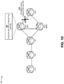
- the network may include multiple network devices, such as a customer edge network device 1 (CE 1 ), provider edge network device 1 (PE 1 ), route reflector network device (RR), provider edge network device 2 (PE 2 ), provider edge network device 3 (PE 3 ), and customer edge network device 2 (CE 2 ).
- the network may include an Ethernet virtual private network (EVPN) with multihoming.
- EVPN multihoming provides redundancy when a link or one of the PE network devices fails.
- multihoming may enable CE 1 to connect to two PE network devices (e.g., PE 2 and PE 3 ) such that traffic is forwarded using all links between CE 1 and PE 2 and PE 3 .
- PE 2 may include a designated forwarder (DF) for forwarding traffic (e.g., from CE 1 and via PE 1 and RR) to CE 2
- PE 3 may include a backup designated forwarder (BDF) for forwarding traffic to CE 2 when a link fails between PE 2 and CE 2 .
- DF designated forwarder
- BDF backup designated forwarder
- the network may include multiple multihomed PE network devices that act as designated forwarders, backup designated forwarders, non-designated forwarders, and/or the like.
- multiple links may be associated with multiple designated forwarder network devices.
- FIG. 1A depicts two multihomed PE network devices (e.g., PE 2 and PE 3 ) and a single link between PE 2 and CE 2 , implementations described herein may apply to a network that includes multiple multihomed PE network devices, multiple links, and/or the like.
- the endpoint device may provide traffic to and/or receive traffic from the network.
- the traffic from the endpoint device may be provided to CE 1 , and CE 1 may provide the traffic to PE 1 .
- PE 1 may provide the traffic to RR, and RR may provide the traffic to PE 2 as the designated forwarder of the traffic.
- PE 2 may provide the traffic to CE 2 (e.g., via a link provided between PE 2 and CE 2 ), and CE 2 may provide the traffic to another endpoint device (not shown).
- CE 2 may provide the traffic to PE 2 as the designated forwarder, and PE 2 may provide the traffic to the endpoint device (e.g., via RR, PE 1 , and CE 1 ).
- PE 2 may provide, to PE 3 , an advertisement message with a first bidirectional forwarding detection (BFD) discriminator associated with a link between PE 2 and CE 2 .
- the first BFD discriminator may include information identifying the link provided between PE 2 and CE 2 and a state of the link (e.g., operational, failing, and/or the like).
- the link may include an Ethernet signature identifier (ESI) link.
- the advertisement message may include an Ethernet virtual identifier (EVI), an ESI, and/or a virtual local area network (VLAN) advertisement message.
- EVI Ethernet virtual identifier
- VLAN virtual local area network
- PE 2 may receive, from PE 3 , an advertisement message with a second BFD discriminator associated with a link between PE 3 and CE 2 .
- the second BFD discriminator may include information identifying the link provided between PE 3 and CE 2 and a state of the link (e.g., operational, failing, and/or the like).
- the link may include an ESI link.
- the advertisement message may include an EVI, an ESI, and/or a VLAN advertisement message.
- PE 2 may pair the second BFD discriminator with the first BFD discriminator to form a BFD session between PE 2 and PE 3 (e.g., via a link provided between PE 2 and PE 3 ).
- PE 2 may pair the second BFD discriminator with the first BFD discriminator when PE 2 receives the advertisement message with the second BFD discriminator.
- PE 3 may pair the first BFD discriminator with the second BFD discriminator when PE 3 receives the advertisement message with the first BFD discriminator.
- the BFD session may be programmed (e.g., to form a programmed BFD session) and BFD messages may be exchanged between PE 2 and PE 3 .
- BFD is a detection protocol designed to provide fast forwarding-path failure detection times for media types, encapsulations, topologies, routing protocols, and/or the like. BFD may be utilized to detect forwarding path (e.g., link) failures at a uniform rate, rather than at variable rates associated with different protocol hello mechanisms. BFD may make network profiling and planning easier and may make convergence time consistent and predictable. In some implementations, BFD may provide sub-second failure detection between two adjacent devices (e.g., PE 2 and PE 3 ) and may be less processing-resource intensive than other protocol hello messages, since some of the BFD load may be distributed onto the data plane.
- a link failure may occur at the link provided between PE 2 and CE 2 (e.g., the link associated with the first BFD discriminator).
- the link failure may occur when the link connecting PE 2 (e.g., the designated forwarder network device) to CE 2 goes down (e.g., becomes non-operational).
- PE 2 may detect the link failure.
- PE 2 may detect the link failure based on providing a message (e.g., a hello message) to CE 2 and receiving a timeout message in response to the message.
- PE 2 may detect the link failure based on providing the message to CE 2 and not receiving a response message from CE 2 within a predetermined time period.
- PE 2 may detect the link failure based on a BFD session formed between PE 2 and CE 2 . In such implementations, PE 2 and CE 2 may form a BFD session in a similar manner described above for PE 2 and PE 3 in connection with FIG. 1C .
- PE 2 may provide, to PE 3 , a link failure message via the BFD session formed between PE 2 and PE 3 .
- PE 2 may provide the link failure message to PE 3 as soon as PE 2 detects the link failure.
- the link failure message may include a BFD message.
- the BFD message may include an indication of the link failure at the link provided between PE 2 and CE 2 , and may cause PE 3 to be a new designated forwarder of traffic for CE 2 (e.g., instead of PE 2 ).
- PE 3 may determine PE 3 to be the new designated forwarder of traffic for CE 2 and may determine PE 2 or another provider edge network device (e.g., not shown but communicating with CE 2 ) to be a new backup designated forwarder of traffic for CE 2 based on the link failure message. In some implementations, PE 3 may determine that the link between PE 2 and CE 2 has failed (e.g., become non-operational) as soon as PE 3 receives the link failure message (e.g., the BFD message).
- the link failure message e.g., the BFD message
- PE 3 may mark PE 3 as the new designated forwarder of traffic for CE 2 (e.g., via a link provided between PE 3 and CE 2 ) based on determining that the link between PE 2 and CE 2 has failed.
- the link failure message (e.g., the BFD message) may cause PE 3 to be the new designated forwarder of traffic for CE 2 less than one second (e.g., sub-second) after PE 2 detects the link failure at the link provided between PE 2 and CE 2 .
- traffic may be forwarded to CE 2 via PE 3 as the new designated forwarder of traffic for CE 2 , without experiencing any significant traffic loss.
- PE 3 as the designated forwarder, may forward traffic to CE 2 via the link provided between PE 3 and CE 2 . In this way, PE 3 (e.g., the original backup designated forwarder) may become the new designated forwarder of traffic for CE 2 , and the amount of network traffic lost due to the link failure associated with the prior designated forwarder (e.g., PE 2 ) is reduced.
- the BFD session formed between PE 2 and PE 3 may experience a failure prior to occurrence of the link failure at the link provided between PE 2 and CE 2 .
- PE 2 may maintain PE 2 as the designated forwarder of traffic for CE 2 and may maintain PE 3 as the backup designated forwarder of traffic for CE 2 .
- the BFD session failure may occur due to loss of BFD keepalive messages between PE 2 and PE 3 .
- the BFD session failure may indicate a network disconnect between PE 2 and PE 3 but may not necessarily indicate a link failure at the link provided between PE 2 and CE 2 .
- PE 2 and PE 3 may not take any action based on the BFD session failure. Although PE 2 and PE 3 may not communicate during the BFD session failure, RR may still communicate with PE 2 and PE 3 . Furthermore, if both PE 2 and PE 3 are determined to be the designated forwarder of traffic for CE 2 , there will be duplicate designated forwarders of traffic for CE 2 , which is undesirable.
- traffic loss may be greatly reduced during link failure in an EVPN multihoming topology, which may conserve computing resources (e.g., processor resources, memory resources, and/or the like) that would otherwise be wasted in attempting to prevent traffic loss during a link failure and/or retrieve traffic lost during a link failure.
- computing resources e.g., processor resources, memory resources, and/or the like
- implementations described herein use a rigorous, computerized process to perform tasks that were not previously performed. For example, currently there does not exist a technique to reduce traffic loss during link failure in an EVPN multihoming topology.
- the time taken to detect the link failure may be greatly reduced by leveraging data plane mechanisms, which are independent of load in the control plane and other network events.
- FIGS. 1A-1G are provided merely as examples. Other examples may differ from what was described with regard to FIGS. 1A-1G .
- FIG. 2 is a diagram of an example environment 200 in which systems and/or methods, described herein, may be implemented.
- environment 200 may include one or more endpoint devices 210 , a group of network devices 220 (shown as network device 220 - 1 through network device 220 -N), and a network 230 .
- Devices of environment 200 may interconnect via wired connections, wireless connections, or a combination of wired and wireless connections.
- Endpoint device 210 includes one or more devices capable of receiving, generating, storing, processing, and/or providing information, such as information described herein.
- endpoint device 210 may include a mobile phone (e.g., a smart phone, a radiotelephone, etc.), a laptop computer, a tablet computer, a desktop computer, a handheld computer, a gaming device, a wearable communication device (e.g., a smart watch, a pair of smart glasses, a heart rate monitor, a fitness tracker, smart clothing, smart jewelry, a head mounted display, etc.), a network device, or a similar type of device.
- endpoint device 210 may receive network traffic from and/or may provide network traffic to other endpoint devices 210 via network 230 (e.g., by routing packets using network devices 220 as intermediaries).
- Network device 220 includes one or more devices capable of receiving, processing, storing, routing, and/or providing traffic (e.g., a packet, a packet replica, other information or metadata, and/or the like) in a manner described herein.
- network device 220 may include a router, such as a label switching router (LSR), a label edge router (LER), an ingress router, an egress router, a provider router (e.g., a provider edge router, a provider core router, etc.), a virtual router, and/or the like.
- LSR label switching router
- LER label edge router
- provider router e.g., a provider edge router, a provider core router, etc.
- network device 220 may include a gateway, a switch, a firewall, a hub, a bridge, a reverse proxy, a server (e.g., a proxy server, a cloud server, a data center server, etc.), a load balancer, and/or a similar device.
- network device 220 may be a physical device implemented within a housing, such as a chassis.
- network device 220 may be a virtual device implemented by one or more computer devices of a cloud computing environment or a data center.
- a group of network devices 220 may be a group of data center nodes that are used to route traffic flow through network 230 .
- network devices 220 may provide an EVPN multihoming topology.
- Network 230 includes one or more wired and/or wireless networks.
- network 230 may include a packet switched network, a cellular network (e.g., a fifth generation (5G) network, a fourth generation (4G) network, such as a long-term evolution (LTE) network, a third generation (3G) network, a code division multiple access (CDMA) network, a public land mobile network (PLMN), a local area network (LAN), a wide area network (WAN), a metropolitan area network (MAN), a telephone network (e.g., the Public Switched Telephone Network (PSTN)), a private network, an ad hoc network, an intranet, the Internet, a fiber optic-based network, a cloud computing network, or the like, and/or a combination of these or other types of networks.
- a packet switched network e.g., a fifth generation (5G) network, a fourth generation (4G) network, such as a long-term evolution (LTE) network, a third generation (3G) network
- the number and arrangement of devices and networks shown in FIG. 2 are provided as an example. In practice, there may be additional devices and/or networks, fewer devices and/or networks, different devices and/or networks, or differently arranged devices and/or networks than those shown in FIG. 2 . Furthermore, two or more devices shown in FIG. 2 may be implemented within a single device, or a single device shown in FIG. 2 may be implemented as multiple, distributed devices. Additionally, or alternatively, a set of devices (e.g., one or more devices) of environment 200 may perform one or more functions described as being performed by another set of devices of environment 200 .
- FIG. 3 is a diagram of example components of a device 300 .
- Device 300 may correspond to endpoint device 210 and/or network device 220 .
- endpoint device 210 and/or network device 220 may include one or more devices 300 and/or one or more components of device 300 .
- device 300 may include one or more input components 305 - 1 through 305 -A (A ⁇ 1) (hereinafter referred to collectively as input components 305 , and individually as input component 305 ), a switching component 310 , one or more output components 315 - 1 through 315 -B (B ⁇ 1) (hereinafter referred to collectively as output components 315 , and individually as output component 315 ), and a controller 320 .
- Input component 305 may be points of attachment for physical links and may be points of entry for incoming traffic, such as packets. Input component 305 may process incoming traffic, such as by performing data link layer encapsulation or decapsulation. In some implementations, input component 305 may send and/or receive packets. In some implementations, input component 305 may include an input line card that includes one or more packet processing components (e.g., in the form of integrated circuits), such as one or more interface cards (IFCs), packet forwarding components, line card controller components, input ports, processors, memories, and/or input queues. In some implementations, device 300 may include one or more input components 305 .
- packet processing components e.g., in the form of integrated circuits
- IFCs interface cards
- packet forwarding components line card controller components
- input ports e.g., processors, memories, and/or input queues.
- device 300 may include one or more input components 305 .
- Switching component 310 may interconnect input components 305 with output components 315 .
- switching component 310 may be implemented via one or more crossbars, via busses, and/or with shared memories.
- the shared memories may act as temporary buffers to store packets from input components 305 before the packets are eventually scheduled for delivery to output components 315 .
- switching component 310 may enable input components 305 , output components 315 , and/or controller 320 to communicate.
- Output component 315 may store packets and may schedule packets for transmission on output physical links. Output component 315 may support data link layer encapsulation or decapsulation, and/or a variety of higher-level protocols. In some implementations, output component 315 may send packets and/or receive packets. In some implementations, output component 315 may include an output line card that includes one or more packet processing components (e.g., in the form of integrated circuits), such as one or more IFCs, packet forwarding components, line card controller components, output ports, processors, memories, and/or output queues. In some implementations, device 300 may include one or more output components 315 . In some implementations, input component 305 and output component 315 may be implemented by the same set of components (e.g., and input/output component may be a combination of input component 305 and output component 315 ).
- Controller 320 includes a central processing unit (CPU), a graphics processing unit (GPU), an accelerated processing unit (APU), a microprocessor, a microcontroller, a digital signal processor (DSP), a field-programmable gate array (FPGA), an application-specific integrated circuit (ASIC), and/or another type of processor or processing component.
- the processor is implemented in hardware, firmware, or a combination of software and hardware.
- controller 320 may include one or more processors that can be programmed to perform a function.
- controller 320 may include a random-access memory (RAM), a read only memory (ROM), and/or another type of dynamic or static storage device (e.g., a flash memory, a magnetic memory, an optical memory, etc.) that stores information and/or instructions for use by controller 320 .
- RAM random-access memory
- ROM read only memory
- static storage device e.g., a flash memory, a magnetic memory, an optical memory, etc.
- controller 320 may communicate with other devices, networks, and/or systems connected to device 300 to exchange information regarding network topology. Controller 320 may create routing tables based on the network topology information, create forwarding tables based on the routing tables, and forward the forwarding tables to input components 305 and/or output components 315 . Input components 305 and/or output components 315 may use the forwarding tables to perform route lookups for incoming and/or outgoing packets. In some cases, controller 320 may create a session table based on information determined while initializing a link fault detection (e.g., BFD) session, and may forward the session table to input components 305 and/or output components 315 .
- a link fault detection e.g., BFD
- Controller 320 may perform one or more processes described herein. Controller 320 may perform these processes in response to executing software instructions stored by a non-transitory computer-readable medium.
- a computer-readable medium is defined herein as a non-transitory memory device.
- a memory device includes memory space within a single physical storage device or memory space spread across multiple physical storage devices.
- Software instructions may be read into a memory and/or storage component associated with controller 320 from another computer-readable medium or from another device via a communication interface. When executed, software instructions stored in a memory and/or storage component associated with controller 320 may cause controller 320 to perform one or more processes described herein. Additionally, or alternatively, hardwired circuitry may be used in place of or in combination with software instructions to perform one or more processes described herein. Thus, implementations described herein are not limited to any specific combination of hardware circuitry and software.
- device 300 may include additional components, fewer components, different components, or differently arranged components than those shown in FIG. 3 . Additionally, or alternatively, a set of components (e.g., one or more components) of device 300 may perform one or more functions described as being performed by another set of components of device 300 .
- FIG. 4 is a flow chart of an example process 400 for reducing traffic loss during link failure in an EVPN multihoming topology.
- one or more process blocks of FIG. 4 may be performed by a network device, such as a first network device (e.g., network device 220 ).
- one or more process blocks of FIG. 4 may be performed by another device or a group of devices separate from or including the network device, such as an endpoint device (e.g., endpoint device 210 ).
- process 400 may include providing a first advertisement message to a second network device, wherein the first advertisement message includes a first bidirectional forwarding detection (BFD) discriminator associated with a first link between the first network device and a third network device, wherein the first network device is a designated forwarder for the third network device, wherein the second network device is a backup designated forwarder for the third network device, and wherein the first network device, the second network device, and the third network device are included in a network (block 410 ).
- the first network device e.g., using switching component 310 , output component 315 , controller 320 , and/or the like
- the first advertisement message may include a first bidirectional forwarding detection (BFD) discriminator associated with a first link between the first network device and a third network device.
- BFD bidirectional forwarding detection
- the first network device may be a designated forwarder for the third network device
- the second network device may be a backup designated forwarder for the third network device.
- the first network device, the second network device, and the third network device may be included in a network.
- process 400 may include receiving a second advertisement message from the second network device, wherein the second advertisement message includes a second BFD discriminator associated with a second link between the second network device and the third network device (block 420 ).
- the first network device e.g., using input component 305 , switching component 310 , controller 320 , and/or the like
- the second advertisement message may include a second BFD discriminator associated with a second link between the second network device and the third network device.
- process 400 may include pairing the first BFD discriminator and the second BFD discriminator to form a BFD session between the first network device and the second network device (block 430 ).
- the first network device e.g., using switching component 310 , controller 320 , and/or the like
- process 400 may include detecting a link failure associated with the first link between the first network device and the third network device (block 440 ).
- the first network device e.g., using input component 305 , switching component 310 , controller 320 , and/or the like
- process 400 may include providing, via the BFD session, a BFD message to the second network device, wherein the BFD message includes an indication of the link failure, and wherein the BFD message is to cause the second network device to be a new designated forwarder for the third network device (block 450 ).
- the first network device e.g., using switching component 310 , output component 315 , controller 320 , and/or the like
- the BFD message may include an indication of the link failure, and the BFD message may cause the second network device to be a new designated forwarder for the third network device.
- Process 400 may include additional implementations, such as any single implementation or any combination of implementations described below and/or in connection with one or more other processes described elsewhere herein.
- the first advertisement message may include at least one of an Ethernet virtual identifier (EVI), an Ethernet signature identifier (ESI), or a virtual local area network (VLAN) advertisement message
- the second advertisement message may include at least one of an EVI, an ESI, or a VLAN advertisement message.
- the BFD message may cause the first network device to be a new backup designated forwarder for the third network device.
- the first network device may detect, prior to detecting the link failure, a failure of the BFD session, where the first network device is maintained as the designated forwarder for the third network device based on detecting the failure of the BFD session.
- the BFD message may cause the second network device to be the new designated forwarder for the third network device less than one second after the link failure is detected by the first network device.
- the first link and the second link may include Ethernet signature identifier (ESI) links.
- the network may include an Ethernet virtual private network (EVPN) that provides multihoming.
- process 400 may include additional blocks, fewer blocks, different blocks, or differently arranged blocks than those depicted in FIG. 4 . Additionally, or alternatively, two or more of the blocks of process 400 may be performed in parallel.
- FIG. 5 is a flow chart of an example process 500 for reducing traffic loss during link failure in an EVPN multihoming topology.
- one or more process blocks of FIG. 5 may be performed by a network device, such as a first network device (e.g., network device 220 ).
- one or more process blocks of FIG. 5 may be performed by another device or a group of devices separate from or including the network device, such as an endpoint device (e.g., endpoint device 210 ).
- process 500 may include providing a first message to a second network device, wherein the first message includes a first bidirectional forwarding detection (BFD) discriminator associated with a first link between the first network device and a third network device, and wherein the first network device, the second network device, and the third network device are included in a network (block 510 ).
- the first network device e.g., using switching component 310 , output component 315 , controller 320 , and/or the like
- the first message may include a first bidirectional forwarding detection (BFD) discriminator associated with a first link between the first network device and a third network device, and the first network device, the second network device, and the third network device may be included in a network.
- BFD bidirectional forwarding detection
- process 500 may include receiving a second message from the second network device, wherein the second message includes a second BFD discriminator associated with a second link between the second network device and the third network device (block 520 ).
- the first network device e.g., using input component 305 , switching component 310 , controller 320 , and/or the like
- the second message may include a second BFD discriminator associated with a second link between the second network device and the third network device.
- process 500 may include permitting a BFD session between the first network device and the second network device based on the first BFD discriminator and the second BFD discriminator (block 530 ).
- the first network device e.g., using switching component 310 , output component 315 , controller 320 , and/or the like
- process 500 may include detecting a link failure associated with the first link between the first network device and the third network device (block 540 ).
- the first network device e.g., using input component 305 , switching component 310 , controller 320 , and/or the like
- process 500 may include providing, via the BFD session, a BFD message to the second network device, wherein the BFD message includes an indication of the link failure, and wherein the BFD message is to cause the second network device to be a designated forwarder for the third network device (block 550 ).
- the first network device e.g., using switching component 310 , output component 315 , controller 320 , and/or the like
- the BFD message may include an indication of the link failure
- the BFD message may cause the second network device to be a designated forwarder for the third network device.
- Process 500 may include additional implementations, such as any single implementation or any combination of implementations described below and/or in connection with one or more other processes described elsewhere herein.
- the first network device may be the designated forwarder for the third network device prior to the link failure
- the second network device may be a backup designated forwarder for the third network device prior to the link failure
- the first message and the second message may include at least one of Ethernet virtual identifier (EVI), Ethernet signature identifier (ESI), or virtual local area network (VLAN) advertisement messages.
- EVI Ethernet virtual identifier
- ESI Ethernet signature identifier
- VLAN virtual local area network
- the first network device may detect, prior to detecting the link failure, a failure of the BFD session, where the first network device is maintained as the designated forwarder for the third network device based on detecting the failure of the BFD session.
- the BFD message may cause the second network device to be the designated forwarder for the third network device less than one second after the link failure is detected by the first network device.
- the BFD message may cause the second network device to communicate traffic with the third network device, via the second link, after causing the second network device to be the designated forwarder for the third network device.
- the network may include an Ethernet virtual private network (EVPN) that provides multihoming.
- EVPN Ethernet virtual private network
- process 500 may include additional blocks, fewer blocks, different blocks, or differently arranged blocks than those depicted in FIG. 5 . Additionally, or alternatively, two or more of the blocks of process 500 may be performed in parallel.
- FIG. 6 is a flow chart of an example process 600 for reducing traffic loss during link failure in an EVPN multihoming topology.
- one or more process blocks of FIG. 6 may be performed by a network device, such as a first network device (e.g., network device 220 ).
- one or more process blocks of FIG. 6 may be performed by another device or a group of devices separate from or including the network device, such as an endpoint device (e.g., endpoint device 210 ).
- process 600 may include permitting a bidirectional forwarding detection (BFD) session with a second network device, wherein the first network device is a designated forwarder for a third network device, wherein a first link is provided between the first network device and the third network device, wherein the second network device is a backup designated forwarder for the third network device, wherein a second link is provided between the second network device and the third network device, and wherein the first network device, the second network device, and the third network device are included in a network (block 610 ).
- BFD bidirectional forwarding detection
- the first network device may permit a bidirectional forwarding detection (BFD) session with a second network device, as described above in connection with FIGS. 1A-2 .
- the first network device may be a designated forwarder for a third network device, and a first link may be provided between the first network device and the third network device.
- the second network device may be a backup designated forwarder for the third network device, and a second link may be provided between the second network device and the third network device.
- the first network device, the second network device, and the third network device may be included in a network.
- process 600 may include detecting a link failure associated with the first link between the first network device and the third network device (block 620 ).
- the first network device e.g., using input component 305 , switching component 310 , controller 320 , and/or the like
- process 600 may include providing, via the BFD session, a BFD message to the second network device, wherein the BFD message includes an indication of the link failure, and wherein the BFD message is to cause the second network device to be a new designated forwarder for the third network device (block 630 ).
- the first network device e.g., using switching component 310 , output component 315 , controller 320 , and/or the like
- the BFD message may include an indication of the link failure
- the BFD message may cause the second network device to be a new designated forwarder for the third network device.
- Process 600 may include additional implementations, such as any single implementation or any combination of implementations described below and/or in connection with one or more other processes described elsewhere herein.
- the first network device may provide a first advertisement message to the second network device, where the first advertisement message includes a first BFD discriminator associated with the first link between the first network device and a third network device, and may receive a second advertisement message from the second network device, where the second advertisement message includes a second BFD discriminator associated with the second link between the second network device and the third network device. Additionally, the first network device may pair the first BFD discriminator and the second BFD discriminator, and, when permitting the BFD session with the second network device, may permit the BFD session with the second network device based on pairing the first BFD discriminator and the second BFD discriminator.
- the BFD message may cause the first network device to be a new backup designated forwarder for the third network device.
- the first network device may detect, prior to detecting the link failure, a failure of the BFD session, where the first network device is maintained as the designated forwarder for the third network device based on detecting the failure of the BFD session, and where the second network device is maintained as the backup designated forwarder for the third network device based on detecting the failure of the BFD session.
- the BFD message may cause the second network device to be the new designated forwarder for the third network device less than one second after the link failure is detected by the first network device.
- the first link and the second link may include Ethernet signature identifier (ESI) links
- the network may include an Ethernet virtual private network (EVPN) that provides multihoming.
- process 600 may include additional blocks, fewer blocks, different blocks, or differently arranged blocks than those depicted in FIG. 6 . Additionally, or alternatively, two or more of the blocks of process 600 may be performed in parallel.
- component is intended to be broadly construed as hardware, firmware, or a combination of hardware and software.
Landscapes
- Engineering & Computer Science (AREA)
- Computer Networks & Wireless Communication (AREA)
- Signal Processing (AREA)
- Environmental & Geological Engineering (AREA)
- Data Exchanges In Wide-Area Networks (AREA)
Abstract
A first network device permits a bidirectional forwarding detection (BFD) session with a second network device. The first network device is a designated forwarder for a third network device, a first link is provided between the first network device and the third network device, the second network device is a backup designated forwarder for the third network device, a second link is provided between the second network device and the third network device. The first network device detects a link failure associated with the first link between the first network device and the third network device, and provides, via the BFD session, a BFD message to the second network device. The BFD message includes an indication of the link failure, and the BFD message is to cause the second network device to be a new designated forwarder for the third network device.
Description
An Ethernet virtual private network (VPN) (EVPN) is a standards-based technology that provides virtual multipoint bridged connectivity between different Layer 2 domains over an Internet protocol (IP) or an IP/multiprotocol label switching (MPLS) backbone network. Like other VPN technologies, such as IP VPN and virtual private local area network (LAN) service (VPLS), EVPN instances are configured on provider edge (PE) network devices (e.g., routers, switches, and/or the like) to maintain logical service separation between customer endpoint devices. The PE network devices connect to customer edge (CE) network devices (e.g., routers, switches, host devices, and/or the like). The PE network devices then exchange reachability information using multiprotocol border gateway protocol (BGP) (MP-BGP), and encapsulated traffic is forwarded between the PE network devices.
According to some implementations, a method may include providing, by a first network device, a first advertisement message to a second network device, wherein the first advertisement message may include a first bidirectional forwarding detection (BFD) discriminator associated with a first link between the first network device and a third network device, wherein the first network device may be a designated forwarder for the third network device, wherein the second network device may be a backup designated forwarder for the third network device, and wherein the first network device, the second network device, and the third network device may be included in a network. The method may include receiving a second advertisement message from the second network device, wherein the second advertisement message may include a second BFD discriminator associated with a second link between the second network device and the third network device. The method may include pairing the first BFD discriminator and the second BFD discriminator to form a BFD session between the first network device and the second network device, and detecting a link failure associated with the first link between the first network device and the third network device. The method may include providing, via the BFD session, a BFD message to the second network device, wherein the BFD message may include an indication of the link failure, and wherein the BFD message may cause the second network device to be a new designated forwarder for the third network device.
According to some implementations, a first network device may include one or more memories, and one or more processors to provide a first message to a second network device, wherein the first message may include a first bidirectional forwarding detection (BFD) discriminator associated with a first link between the first network device and a third network device, and wherein the first network device, the second network device, and the third network device may be included in a network. The one or more processors may receive a second message from the second network device, wherein the second message may include a second BFD discriminator associated with a second link between the second network device and the third network device. The one or more processors may permit a BFD session between the first network device and the second network device based on the first BFD discriminator and the second BFD discriminator, and may detect a link failure associated with the first link between the first network device and the third network device. The one or more processors may provide, via the BFD session, a BFD message to the second network device, wherein the BFD message may include an indication of the link failure, and wherein the BFD message may cause the second network device to be a designated forwarder for the third network device.
According to some implementations, a non-transitory computer-readable medium may store instructions that include one or more instructions that, when executed by one or more processors of a first network device, cause the one or more processors to permit a bidirectional forwarding detection (BFD) session with a second network device, wherein the first network device may be a designated forwarder for a third network device, wherein a first link may be provided between the first network device and the third network device, wherein the second network device may be a backup designated forwarder for the third network device, wherein a second link may be provided between the second network device and the third network device, and wherein the first network device, the second network device, and the third network device may be included in a network. The one or more instructions may cause the one or more processors to detect a link failure associated with the first link between the first network device and the third network device, and provide, via the BFD session, a BFD message to the second network device, wherein the BFD message may include an indication of the link failure, and wherein the BFD message may cause the second network device to be a new designated forwarder for the third network device.
The following detailed description of example implementations refers to the accompanying drawings. The same reference numbers in different drawings may identify the same or similar elements.
EVPN multihoming provides redundancy when a link or one of the PE network devices fails. In either case, traffic flows from a CE network device towards a PE network device, using remaining active links. Multihoming enables a CE network device to connect to two or more PE network devices such that traffic is forwarded using all links between the CE network device and the two or more PE network devices. However, when a link between a first PE network device (e.g., a designated forwarder (DF) of traffic) and a CE network device fails, a second PE network device (e.g., a backup DF (BDF) of traffic) must change from being the backup designated forwarder to the designated forwarder as soon as possible to begin forwarding traffic and to avoid traffic loss. Unfortunately, the time required for the second PE network device to change from being the backup designated forwarder to the designated forwarder is approximately ten to twenty seconds, which is too time consuming and leads to network traffic disruption and/or loss.
Some implementations described herein provide a first network device that reduces traffic loss during link failure in an EVPN multihoming topology. For example, the first network device may provide a first message to a second network device, wherein the first message may include a first bidirectional forwarding detection (BFD) discriminator associated with a first link between the first network device and a third network device, and wherein the first network device, the second network device, and the third network device may be included in a network. The first network device may receive a second message from the second network device, wherein the second message may include a second BFD discriminator associated with a second link between the second network device and the third network device. The first network device may permit a BFD session between the first network device and the second network device based on the first BFD discriminator and the second BFD discriminator, and may detect a link failure associated with the first link between the first network device and the third network device. The first network device may provide, via the BFD session, a BFD message to the second network device, wherein the BFD message may include an indication of the link failure, and wherein the BFD message may cause the second network device to be a designated forwarder for the third network device.
In this way, when a link failure occurs with a designated forwarder network device, a backup designated forwarded network device may be alerted and immediately become the designated forwarder network device for a network, which greatly reduces network traffic loss. A time taken to detect the link failure may be greatly reduced by leveraging data plane mechanisms, which are independent of load in the control plane and other network events.
While the following description focuses on an Ethernet virtual private network (VPN) (EVPN), implementations described herein are equally applicable to other types of protocols, networks, VPNs, and/or the like.
In some implementations, the network may include multiple multihomed PE network devices that act as designated forwarders, backup designated forwarders, non-designated forwarders, and/or the like. In some implementations, multiple links may be associated with multiple designated forwarder network devices. Although FIG. 1A depicts two multihomed PE network devices (e.g., PE2 and PE3) and a single link between PE2 and CE2, implementations described herein may apply to a network that includes multiple multihomed PE network devices, multiple links, and/or the like.
As further shown in FIG. 1A , and by reference number 105, the endpoint device may provide traffic to and/or receive traffic from the network. In some implementations, the traffic from the endpoint device may be provided to CE1, and CE1 may provide the traffic to PE1. PE1 may provide the traffic to RR, and RR may provide the traffic to PE2 as the designated forwarder of the traffic. PE2 may provide the traffic to CE2 (e.g., via a link provided between PE2 and CE2), and CE2 may provide the traffic to another endpoint device (not shown). In some implementations, if CE2 receives traffic (e.g., destined for the endpoint device) from the other endpoint device, CE2 may provide the traffic to PE2 as the designated forwarder, and PE2 may provide the traffic to the endpoint device (e.g., via RR, PE1, and CE1).
As shown in FIG. 1B , and by reference number 110, PE2 may provide, to PE3, an advertisement message with a first bidirectional forwarding detection (BFD) discriminator associated with a link between PE2 and CE2. In some implementations, the first BFD discriminator may include information identifying the link provided between PE2 and CE2 and a state of the link (e.g., operational, failing, and/or the like). In some implementations, the link may include an Ethernet signature identifier (ESI) link. In some implementations, the advertisement message may include an Ethernet virtual identifier (EVI), an ESI, and/or a virtual local area network (VLAN) advertisement message.
As further shown in FIG. 1B , and by reference number 115, PE2 may receive, from PE3, an advertisement message with a second BFD discriminator associated with a link between PE3 and CE2. In some implementations, the second BFD discriminator may include information identifying the link provided between PE3 and CE2 and a state of the link (e.g., operational, failing, and/or the like). In some implementations, the link may include an ESI link. In some implementations, the advertisement message may include an EVI, an ESI, and/or a VLAN advertisement message.
As shown in FIG. 1C , and by reference number 120, PE2 may pair the second BFD discriminator with the first BFD discriminator to form a BFD session between PE2 and PE3 (e.g., via a link provided between PE2 and PE3). In some implementations, PE2 may pair the second BFD discriminator with the first BFD discriminator when PE2 receives the advertisement message with the second BFD discriminator. In some implementations, PE3 may pair the first BFD discriminator with the second BFD discriminator when PE3 receives the advertisement message with the first BFD discriminator.
As further shown in FIG. 1C , and by reference number 125, once the first BFD discriminator and the second BFD discriminator are paired, the BFD session may be programmed (e.g., to form a programmed BFD session) and BFD messages may be exchanged between PE2 and PE3. BFD is a detection protocol designed to provide fast forwarding-path failure detection times for media types, encapsulations, topologies, routing protocols, and/or the like. BFD may be utilized to detect forwarding path (e.g., link) failures at a uniform rate, rather than at variable rates associated with different protocol hello mechanisms. BFD may make network profiling and planning easier and may make convergence time consistent and predictable. In some implementations, BFD may provide sub-second failure detection between two adjacent devices (e.g., PE2 and PE3) and may be less processing-resource intensive than other protocol hello messages, since some of the BFD load may be distributed onto the data plane.
As shown in FIG. 1D , and by reference number 130, a link failure may occur at the link provided between PE2 and CE2 (e.g., the link associated with the first BFD discriminator). In some implementations, the link failure may occur when the link connecting PE2 (e.g., the designated forwarder network device) to CE2 goes down (e.g., becomes non-operational).
As further shown in FIG. 1D , and by reference number 135, when the link failure occurs at the link provided between PE2 and CE2, PE2 may detect the link failure. In some implementations, PE2 may detect the link failure based on providing a message (e.g., a hello message) to CE2 and receiving a timeout message in response to the message. In some implementations, PE2 may detect the link failure based on providing the message to CE2 and not receiving a response message from CE2 within a predetermined time period. In some implementations, PE2 may detect the link failure based on a BFD session formed between PE2 and CE2. In such implementations, PE2 and CE2 may form a BFD session in a similar manner described above for PE2 and PE3 in connection with FIG. 1C .
As shown in FIG. 1E , and by reference number 140, PE2 may provide, to PE3, a link failure message via the BFD session formed between PE2 and PE3. In some implementations, PE2 may provide the link failure message to PE3 as soon as PE2 detects the link failure. In some implementations, the link failure message may include a BFD message. In some implementations, the BFD message may include an indication of the link failure at the link provided between PE2 and CE2, and may cause PE3 to be a new designated forwarder of traffic for CE2 (e.g., instead of PE2).
As further shown in FIG. 1E , and by reference number 145, PE3 may determine PE3 to be the new designated forwarder of traffic for CE2 and may determine PE2 or another provider edge network device (e.g., not shown but communicating with CE2) to be a new backup designated forwarder of traffic for CE2 based on the link failure message. In some implementations, PE3 may determine that the link between PE2 and CE2 has failed (e.g., become non-operational) as soon as PE3 receives the link failure message (e.g., the BFD message). In such implementations, PE3 may mark PE3 as the new designated forwarder of traffic for CE2 (e.g., via a link provided between PE3 and CE2) based on determining that the link between PE2 and CE2 has failed. In some implementations, the link failure message (e.g., the BFD message) may cause PE3 to be the new designated forwarder of traffic for CE2 less than one second (e.g., sub-second) after PE2 detects the link failure at the link provided between PE2 and CE2.
As shown in FIG. 1F , and by reference number 150, traffic may be forwarded to CE2 via PE3 as the new designated forwarder of traffic for CE2, without experiencing any significant traffic loss. In some implementations, PE3, as the designated forwarder, may forward traffic to CE2 via the link provided between PE3 and CE2. In this way, PE3 (e.g., the original backup designated forwarder) may become the new designated forwarder of traffic for CE2, and the amount of network traffic lost due to the link failure associated with the prior designated forwarder (e.g., PE2) is reduced.
As shown in FIG. 1G , and by reference number 155, the BFD session formed between PE2 and PE3 may experience a failure prior to occurrence of the link failure at the link provided between PE2 and CE2. In such situations, and as shown by reference number 160 in FIG. 1G , PE2 may maintain PE2 as the designated forwarder of traffic for CE2 and may maintain PE3 as the backup designated forwarder of traffic for CE2. In some implementations, the BFD session failure may occur due to loss of BFD keepalive messages between PE2 and PE3. The BFD session failure may indicate a network disconnect between PE2 and PE3 but may not necessarily indicate a link failure at the link provided between PE2 and CE2. Thus, PE2 and PE3 may not take any action based on the BFD session failure. Although PE2 and PE3 may not communicate during the BFD session failure, RR may still communicate with PE2 and PE3. Furthermore, if both PE2 and PE3 are determined to be the designated forwarder of traffic for CE2, there will be duplicate designated forwarders of traffic for CE2, which is undesirable.
In this way, traffic loss may be greatly reduced during link failure in an EVPN multihoming topology, which may conserve computing resources (e.g., processor resources, memory resources, and/or the like) that would otherwise be wasted in attempting to prevent traffic loss during a link failure and/or retrieve traffic lost during a link failure. Furthermore, implementations described herein use a rigorous, computerized process to perform tasks that were not previously performed. For example, currently there does not exist a technique to reduce traffic loss during link failure in an EVPN multihoming topology. Finally, the time taken to detect the link failure may be greatly reduced by leveraging data plane mechanisms, which are independent of load in the control plane and other network events.
As indicated above, FIGS. 1A-1G are provided merely as examples. Other examples may differ from what was described with regard to FIGS. 1A-1G .
The number and arrangement of devices and networks shown in FIG. 2 are provided as an example. In practice, there may be additional devices and/or networks, fewer devices and/or networks, different devices and/or networks, or differently arranged devices and/or networks than those shown in FIG. 2 . Furthermore, two or more devices shown in FIG. 2 may be implemented within a single device, or a single device shown in FIG. 2 may be implemented as multiple, distributed devices. Additionally, or alternatively, a set of devices (e.g., one or more devices) of environment 200 may perform one or more functions described as being performed by another set of devices of environment 200.
In some implementations, controller 320 may include a random-access memory (RAM), a read only memory (ROM), and/or another type of dynamic or static storage device (e.g., a flash memory, a magnetic memory, an optical memory, etc.) that stores information and/or instructions for use by controller 320.
In some implementations, controller 320 may communicate with other devices, networks, and/or systems connected to device 300 to exchange information regarding network topology. Controller 320 may create routing tables based on the network topology information, create forwarding tables based on the routing tables, and forward the forwarding tables to input components 305 and/or output components 315. Input components 305 and/or output components 315 may use the forwarding tables to perform route lookups for incoming and/or outgoing packets. In some cases, controller 320 may create a session table based on information determined while initializing a link fault detection (e.g., BFD) session, and may forward the session table to input components 305 and/or output components 315.
Software instructions may be read into a memory and/or storage component associated with controller 320 from another computer-readable medium or from another device via a communication interface. When executed, software instructions stored in a memory and/or storage component associated with controller 320 may cause controller 320 to perform one or more processes described herein. Additionally, or alternatively, hardwired circuitry may be used in place of or in combination with software instructions to perform one or more processes described herein. Thus, implementations described herein are not limited to any specific combination of hardware circuitry and software.
The number and arrangement of components shown in FIG. 3 are provided as an example. In practice, device 300 may include additional components, fewer components, different components, or differently arranged components than those shown in FIG. 3 . Additionally, or alternatively, a set of components (e.g., one or more components) of device 300 may perform one or more functions described as being performed by another set of components of device 300.
As shown in FIG. 4 , process 400 may include providing a first advertisement message to a second network device, wherein the first advertisement message includes a first bidirectional forwarding detection (BFD) discriminator associated with a first link between the first network device and a third network device, wherein the first network device is a designated forwarder for the third network device, wherein the second network device is a backup designated forwarder for the third network device, and wherein the first network device, the second network device, and the third network device are included in a network (block 410). For example, the first network device (e.g., using switching component 310, output component 315, controller 320, and/or the like) may provide a first advertisement message to a second network device, as described above in connection with FIGS. 1A-2 . In some implementations, the first advertisement message may include a first bidirectional forwarding detection (BFD) discriminator associated with a first link between the first network device and a third network device. In some implementations, the first network device may be a designated forwarder for the third network device, and the second network device may be a backup designated forwarder for the third network device. In some implementations, the first network device, the second network device, and the third network device may be included in a network.
As further shown in FIG. 4 , process 400 may include receiving a second advertisement message from the second network device, wherein the second advertisement message includes a second BFD discriminator associated with a second link between the second network device and the third network device (block 420). For example, the first network device (e.g., using input component 305, switching component 310, controller 320, and/or the like) may receive a second advertisement message from the second network device, as described above in connection with FIGS. 1A-2 . In some implementations, the second advertisement message may include a second BFD discriminator associated with a second link between the second network device and the third network device.
As further shown in FIG. 4 , process 400 may include pairing the first BFD discriminator and the second BFD discriminator to form a BFD session between the first network device and the second network device (block 430). For example, the first network device (e.g., using switching component 310, controller 320, and/or the like) may pair the first BFD discriminator and the second BFD discriminator to form a BFD session between the first network device and the second network device, as described above in connection with FIGS. 1A-2 .
As further shown in FIG. 4 , process 400 may include detecting a link failure associated with the first link between the first network device and the third network device (block 440). For example, the first network device (e.g., using input component 305, switching component 310, controller 320, and/or the like) may detect a link failure associated with the first link between the first network device and the third network device, as described above in connection with FIGS. 1A-2 .
As further shown in FIG. 4 , process 400 may include providing, via the BFD session, a BFD message to the second network device, wherein the BFD message includes an indication of the link failure, and wherein the BFD message is to cause the second network device to be a new designated forwarder for the third network device (block 450). For example, the first network device (e.g., using switching component 310, output component 315, controller 320, and/or the like) may provide, via the BFD session, a BFD message to the second network device, as described above in connection with FIGS. 1A-2 . In some implementations, the BFD message may include an indication of the link failure, and the BFD message may cause the second network device to be a new designated forwarder for the third network device.
In some implementations, the first advertisement message may include at least one of an Ethernet virtual identifier (EVI), an Ethernet signature identifier (ESI), or a virtual local area network (VLAN) advertisement message, and the second advertisement message may include at least one of an EVI, an ESI, or a VLAN advertisement message. In some implementations, the BFD message may cause the first network device to be a new backup designated forwarder for the third network device.
In some implementations, the first network device may detect, prior to detecting the link failure, a failure of the BFD session, where the first network device is maintained as the designated forwarder for the third network device based on detecting the failure of the BFD session.
In some implementations, the BFD message may cause the second network device to be the new designated forwarder for the third network device less than one second after the link failure is detected by the first network device. In some implementations, the first link and the second link may include Ethernet signature identifier (ESI) links. In some implementations, the network may include an Ethernet virtual private network (EVPN) that provides multihoming.
Although FIG. 4 shows example blocks of process 400, in some implementations process 400 may include additional blocks, fewer blocks, different blocks, or differently arranged blocks than those depicted in FIG. 4 . Additionally, or alternatively, two or more of the blocks of process 400 may be performed in parallel.
As shown in FIG. 5 , process 500 may include providing a first message to a second network device, wherein the first message includes a first bidirectional forwarding detection (BFD) discriminator associated with a first link between the first network device and a third network device, and wherein the first network device, the second network device, and the third network device are included in a network (block 510). For example, the first network device (e.g., using switching component 310, output component 315, controller 320, and/or the like) may provide a first message to a second network device, as described above in connection with FIGS. 1A-2 . In some implementations, the first message may include a first bidirectional forwarding detection (BFD) discriminator associated with a first link between the first network device and a third network device, and the first network device, the second network device, and the third network device may be included in a network.
As further shown in FIG. 5 , process 500 may include receiving a second message from the second network device, wherein the second message includes a second BFD discriminator associated with a second link between the second network device and the third network device (block 520). For example, the first network device (e.g., using input component 305, switching component 310, controller 320, and/or the like) may receive a second message from the second network device, as described above in connection with FIGS. 1A-2 . In some implementations, the second message may include a second BFD discriminator associated with a second link between the second network device and the third network device.
As further shown in FIG. 5 , process 500 may include permitting a BFD session between the first network device and the second network device based on the first BFD discriminator and the second BFD discriminator (block 530). For example, the first network device (e.g., using switching component 310, output component 315, controller 320, and/or the like) may permit a BFD session between the first network device and the second network device based on the first BFD discriminator and the second BFD discriminator, as described above in connection with FIGS. 1A-2 .
As further shown in FIG. 5 , process 500 may include detecting a link failure associated with the first link between the first network device and the third network device (block 540). For example, the first network device (e.g., using input component 305, switching component 310, controller 320, and/or the like) may detect a link failure associated with the first link between the first network device and the third network device, as described above in connection with FIGS. 1A-2 .
As further shown in FIG. 5 , process 500 may include providing, via the BFD session, a BFD message to the second network device, wherein the BFD message includes an indication of the link failure, and wherein the BFD message is to cause the second network device to be a designated forwarder for the third network device (block 550). For example, the first network device (e.g., using switching component 310, output component 315, controller 320, and/or the like) may provide, via the BFD session, a BFD message to the second network device, as described above in connection with FIGS. 1A-2 . In some implementations, the BFD message may include an indication of the link failure, and the BFD message may cause the second network device to be a designated forwarder for the third network device.
In some implementations, the first network device may be the designated forwarder for the third network device prior to the link failure, and the second network device may be a backup designated forwarder for the third network device prior to the link failure. In some implementations, the first message and the second message may include at least one of Ethernet virtual identifier (EVI), Ethernet signature identifier (ESI), or virtual local area network (VLAN) advertisement messages.
In some implementations, the first network device may detect, prior to detecting the link failure, a failure of the BFD session, where the first network device is maintained as the designated forwarder for the third network device based on detecting the failure of the BFD session. In some implementations, the BFD message may cause the second network device to be the designated forwarder for the third network device less than one second after the link failure is detected by the first network device.
In some implementations, the BFD message may cause the second network device to communicate traffic with the third network device, via the second link, after causing the second network device to be the designated forwarder for the third network device. In some implementations, the network may include an Ethernet virtual private network (EVPN) that provides multihoming.
Although FIG. 5 shows example blocks of process 500, in some implementations process 500 may include additional blocks, fewer blocks, different blocks, or differently arranged blocks than those depicted in FIG. 5 . Additionally, or alternatively, two or more of the blocks of process 500 may be performed in parallel.
As shown in FIG. 6 , process 600 may include permitting a bidirectional forwarding detection (BFD) session with a second network device, wherein the first network device is a designated forwarder for a third network device, wherein a first link is provided between the first network device and the third network device, wherein the second network device is a backup designated forwarder for the third network device, wherein a second link is provided between the second network device and the third network device, and wherein the first network device, the second network device, and the third network device are included in a network (block 610). For example, the first network device (e.g., using input component 305, switching component 310, output component 315, controller 320, and/or the like) may permit a bidirectional forwarding detection (BFD) session with a second network device, as described above in connection with FIGS. 1A-2 . In some implementations, the first network device may be a designated forwarder for a third network device, and a first link may be provided between the first network device and the third network device. In some implementations, the second network device may be a backup designated forwarder for the third network device, and a second link may be provided between the second network device and the third network device. In some implementations, the first network device, the second network device, and the third network device may be included in a network.
As further shown in FIG. 6 , process 600 may include detecting a link failure associated with the first link between the first network device and the third network device (block 620). For example, the first network device (e.g., using input component 305, switching component 310, controller 320, and/or the like) may detect a link failure associated with the first link between the first network device and the third network device, as described above in connection with FIGS. 1A-2 .
As further shown in FIG. 6 , process 600 may include providing, via the BFD session, a BFD message to the second network device, wherein the BFD message includes an indication of the link failure, and wherein the BFD message is to cause the second network device to be a new designated forwarder for the third network device (block 630). For example, the first network device (e.g., using switching component 310, output component 315, controller 320, and/or the like) may provide, via the BFD session, a BFD message to the second network device, as described above in connection with FIGS. 1A-2 . In some implementations, the BFD message may include an indication of the link failure, and the BFD message may cause the second network device to be a new designated forwarder for the third network device.
In some implementations, the first network device may provide a first advertisement message to the second network device, where the first advertisement message includes a first BFD discriminator associated with the first link between the first network device and a third network device, and may receive a second advertisement message from the second network device, where the second advertisement message includes a second BFD discriminator associated with the second link between the second network device and the third network device. Additionally, the first network device may pair the first BFD discriminator and the second BFD discriminator, and, when permitting the BFD session with the second network device, may permit the BFD session with the second network device based on pairing the first BFD discriminator and the second BFD discriminator.
In some implementations, the BFD message may cause the first network device to be a new backup designated forwarder for the third network device. In some implementations, the first network device may detect, prior to detecting the link failure, a failure of the BFD session, where the first network device is maintained as the designated forwarder for the third network device based on detecting the failure of the BFD session, and where the second network device is maintained as the backup designated forwarder for the third network device based on detecting the failure of the BFD session.
In some implementations, the BFD message may cause the second network device to be the new designated forwarder for the third network device less than one second after the link failure is detected by the first network device. In some implementations, the first link and the second link may include Ethernet signature identifier (ESI) links, and the network may include an Ethernet virtual private network (EVPN) that provides multihoming.
Although FIG. 6 shows example blocks of process 600, in some implementations process 600 may include additional blocks, fewer blocks, different blocks, or differently arranged blocks than those depicted in FIG. 6 . Additionally, or alternatively, two or more of the blocks of process 600 may be performed in parallel.
The foregoing disclosure provides illustration and description, but is not intended to be exhaustive or to limit the implementations to the precise form disclosed. Modifications and variations may be made in light of the above disclosure or may be acquired from practice of the implementations.
As used herein, the term “component” is intended to be broadly construed as hardware, firmware, or a combination of hardware and software.
It will be apparent that systems and/or methods, described herein, may be implemented in different forms of hardware, firmware, or a combination of hardware and software. The actual specialized control hardware or software code used to implement these systems and/or methods is not limiting of the implementations. Thus, the operation and behavior of the systems and/or methods were described herein without reference to specific software code—it being understood that software and hardware may be designed to implement the systems and/or methods based on the description herein.
Even though particular combinations of features are recited in the claims and/or disclosed in the specification, these combinations are not intended to limit the disclosure of various implementations. In fact, many of these features may be combined in ways not specifically recited in the claims and/or disclosed in the specification. Although each dependent claim listed below may directly depend on only one claim, the disclosure of various implementations includes each dependent claim in combination with every other claim in the claim set.
No element, act, or instruction used herein should be construed as critical or essential unless explicitly described as such. Also, as used herein, the articles “a” and “an” are intended to include one or more items, and may be used interchangeably with “one or more.” Furthermore, as used herein, the term “set” is intended to include one or more items (e.g., related items, unrelated items, a combination of related and unrelated items, etc.), and may be used interchangeably with “one or more.” Where only one item is intended, the phrase “only one” or similar language is used. Also, as used herein, the terms “has,” “have,” “having,” or the like are intended to be open-ended terms. Further, the phrase “based on” is intended to mean “based, at least in part, on” unless explicitly stated otherwise.
Claims (20)
1. A method, comprising:
providing, by a first network device, a first advertisement message to a second network device,
wherein the first advertisement message includes a first bidirectional forwarding detection (BFD) discriminator associated with a first link between the first network device and a third network device, the first BFD discriminator including information identifying the first link and a state of the first link,
wherein the first network device is a designated forwarder for the third network device,
wherein the second network device is a backup designated forwarder for the third network device, and
wherein the first network device, the second network device, and the third network device are included in a network;
receiving, by the first network device, a second advertisement message from the second network device,
wherein the second advertisement message includes a second BFD discriminator associated with a second link between the second network device and the third network device, the second BFD discriminator including information identifying the second link and a state of the second link;
pairing, by the first network device, the first BFD discriminator and the second BFD discriminator to form a BFD session between the first network device and the second network device;
detecting, by the first network device, a link failure associated with the first link between the first network device and the third network device; and
providing, by the first network device and via the BFD session, a BFD message to the second network device,
wherein the BFD message includes an indication of the link failure, and
wherein the BFD message is to cause the second network device to be a new designated forwarder for the third network device.
2. The method of claim 1 , wherein:
the first advertisement message comprises at least one of an Ethernet virtual identifier (EVI), an Ethernet signature identifier (ESI), or a virtual local area network (VLAN) advertisement message, and
the second advertisement message comprises at least one of an EVI, an ESI, or a VLAN advertisement message.
3. The method of claim 1 , wherein the BFD message is to cause the first network device to be a new backup designated forwarder for the third network device.
4. The method of claim 1 , further comprising:
detecting, prior to detecting the link failure, a failure of the BFD session,
wherein the first network device is maintained as the designated forwarder for the third network device based on detecting the failure of the BFD session.
5. The method of claim 1 , wherein the first link and the second link include Ethernet signature identifier (ESI) links.
6. The method of claim 1 , wherein the network includes an Ethernet virtual private network (EVPN) that provides multihoming.
7. The method of claim 1 ,
wherein the information identifying the state of the first link identifies whether the first link is operational or failing, and
wherein the information identifying the state of the second link identifies whether the second link is operational or failing.
8. A first network device, comprising:
one or more memories; and
one or more processors to:
provide a first message to a second network device,
wherein the first message includes a first bidirectional forwarding detection (BFD) discriminator associated with a first link between the first network device and a third network device, the first BFD discriminator including information identifying the first link and a state of the first link, and
wherein the first network device, the second network device, and the third network device are included in a network;
receive a second message from the second network device,
wherein the second message includes a second BFD discriminator associated with a second link between the second network device and the third network device, the second BFD discriminator including information identifying the second link and a state of the second link;
permit a BFD session between the first network device and the second network device based on the first BFD discriminator and the second BFD discriminator;
detect a link failure associated with the first link between the first network device and the third network device; and
provide, via the BFD session, a BFD message to the second network device,
wherein the BFD message includes an indication of the link failure, and
wherein the BFD message is to cause the second network device to be a designated forwarder for the third network device.
9. The first network device of claim 8 , wherein:
the first network device is the designated forwarder for the third network device prior to the link failure, and
the second network device is a backup designated forwarder for the third network device prior to the link failure.
10. The first network device of claim 8 , wherein:
the first message and the second message comprise at least one of Ethernet virtual identifier (EVI), Ethernet signature identifier (ESI), or virtual local area network (VLAN) advertisement messages.
11. The first network device of claim 8 , wherein the one or more processors are further to:
detect, prior to detecting the link failure, a failure of the BFD session,
wherein the first network device is maintained as the designated forwarder for the third network device based on detecting the failure of the BFD session.
12. The first network device of claim 8 , wherein the BFD message is to cause the second network device to communicate traffic with the third network device, via the second link, after causing the second network device to be the designated forwarder for the third network device.
13. The first network device of claim 8 , wherein the network includes an Ethernet virtual private network (EVPN) that provides multihoming.
14. The first network device of claim 8 , wherein at least one of the first link or the second link includes an Ethernet signature identifier link.
15. A non-transitory computer-readable medium storing instructions, the instructions comprising:
one or more instructions that, when executed by one or more processors of a first network device, cause the one or more processors to:
permit a bidirectional forwarding detection (BFD) session with a second network device,
wherein the first network device is a designated forwarder for a third network device,
wherein a first link is provided between the first network device and the third network device,
wherein the second network device is a backup designated forwarder for the third network device,
wherein a second link is provided between the second network device and the third network device, and
wherein the first network device, the second network device, and the third network device are included in a network;
provide a first advertisement message to the second network device,
wherein the first advertisement message includes a first BFD discriminator associated with the first link between the first network device and a third network device, the first BFD discriminator including information identifying the first link and a state of the first link;
receive a second advertisement message from the second network device,
wherein the second advertisement message includes a second BFD discriminator associated with the second link between the second network device and the third network device, the second BFD discriminator including information identifying the second link and a state of the second link;
detect a link failure associated with the first link between the first network device and the third network device; and
provide, via the BFD session, a BFD message to the second network device,
wherein the BFD message includes an indication of the link failure, and
wherein the BFD message is to cause the second network device to be a new designated forwarder for the third network device.
16. The non-transitory computer-readable medium of claim 15 , wherein the instructions further comprise:
one or more instructions that, when executed by the one or more processors, cause the one or more processors to:
provide a first advertisement message to the second network device,
wherein the first advertisement message includes a first BFD discriminator associated with the first link between the first network device and a third network device;
receive a second advertisement message from the second network device,
wherein the second advertisement message includes a second BFD discriminator associated with the second link between the second network device and the third network device;
pair the first BFD discriminator and the second BFD discriminator; and
wherein the one or more instructions, that cause the one or more processors to permit the BFD session with the second network device, cause the one or more processors to:
permit the BFD session with the second network device based on pairing the first BFD discriminator and the second BFD discriminator.
17. The non-transitory computer-readable medium of claim 15 , wherein the BFD message is to cause the first network device to be a new backup designated forwarder for the third network device.
18. The non-transitory computer-readable medium of claim 15 , wherein the instructions further comprise:
one or more instructions that, when executed by the one or more processors, cause the one or more processors to:
detect, prior to detecting the link failure, a failure of the BFD session,
wherein the first network device is maintained as the designated forwarder for the third network device based on detecting the failure of the BFD session, and
wherein the second network device is maintained as the backup designated forwarder for the third network device based on detecting the failure of the BFD session.
19. The non-transitory computer-readable medium of claim 15 , wherein:
the first link and the second link include Ethernet signature identifier (ESI) links, and
the network includes an Ethernet virtual private network (EVPN) that provides multihoming.
20. The non-transitory computer-readable medium of claim 15 , wherein at least one of the first advertisement message or the second advertisement message includes at least one of an Ethernet virtual identifier, an Ethernet signature identifier, or a virtual local area network advertisement message.
Priority Applications (1)
| Application Number | Priority Date | Filing Date | Title |
|---|---|---|---|
| US16/189,408 US10771317B1 (en) | 2018-11-13 | 2018-11-13 | Reducing traffic loss during link failure in an ethernet virtual private network multihoming topology |
Applications Claiming Priority (1)
| Application Number | Priority Date | Filing Date | Title |
|---|---|---|---|
| US16/189,408 US10771317B1 (en) | 2018-11-13 | 2018-11-13 | Reducing traffic loss during link failure in an ethernet virtual private network multihoming topology |
Publications (1)
| Publication Number | Publication Date |
|---|---|
| US10771317B1 true US10771317B1 (en) | 2020-09-08 |
Family
ID=72290187
Family Applications (1)
| Application Number | Title | Priority Date | Filing Date |
|---|---|---|---|
| US16/189,408 Active 2038-11-22 US10771317B1 (en) | 2018-11-13 | 2018-11-13 | Reducing traffic loss during link failure in an ethernet virtual private network multihoming topology |
Country Status (1)
| Country | Link |
|---|---|
| US (1) | US10771317B1 (en) |
Cited By (2)
| Publication number | Priority date | Publication date | Assignee | Title |
|---|---|---|---|---|
| US20230164064A1 (en) * | 2021-11-24 | 2023-05-25 | Google Llc | Fast, Predictable, Dynamic Route Failover in Software-Defined Networks |
| WO2023197644A1 (en) * | 2022-04-15 | 2023-10-19 | 华为技术有限公司 | Cross-segmented network fault detection method, and communication system and related apparatus |
Citations (22)
| Publication number | Priority date | Publication date | Assignee | Title |
|---|---|---|---|---|
| US20090010153A1 (en) * | 2007-07-03 | 2009-01-08 | Cisco Technology, Inc. | Fast remote failure notification |
| US20090161670A1 (en) * | 2007-12-24 | 2009-06-25 | Cisco Technology, Inc. | Fast multicast convergence at secondary designated router or designated forwarder |
| US7561527B1 (en) * | 2003-05-02 | 2009-07-14 | David Katz | Bidirectional forwarding detection |
| US20100023632A1 (en) * | 2006-12-25 | 2010-01-28 | Huawei Technologies Co., Ltd. | Method and system for negotiating the bidirectional forwarding detection session discriminator of pseudo wire |
| US20100329110A1 (en) * | 2009-06-30 | 2010-12-30 | Laurence Rose | Method for reconvergence after failure in a dual-homing network environment |
| US20110032945A1 (en) * | 2009-08-05 | 2011-02-10 | Cisco Technology, Inc. | Signaling of attachment circuit status and automatic discovery of inter-chassis communication peers |
| US20140029419A1 (en) * | 2012-07-27 | 2014-01-30 | Pradeep G. Jain | System, method and apparatus providing mvpn fast failover |
| US8780699B1 (en) * | 2009-10-12 | 2014-07-15 | Juniper Networks, Inc. | Handling switchover of multi-homed connections in VPLS networks |
| US20140307564A1 (en) * | 2012-11-13 | 2014-10-16 | Huawei Technologies Co., Ltd. | Bidirectional forwarding detection bfd session negotiation method, device, and system |
| US9019814B1 (en) * | 2013-08-05 | 2015-04-28 | Juniper Networks, Inc. | Fast failover in multi-homed ethernet virtual private networks |
| US20150236920A1 (en) * | 2012-10-17 | 2015-08-20 | Telefonaktiebolget L M Ericsson (Publ) | Method and apparatus for determining connection information of a link |
| US20160036695A1 (en) * | 2014-08-04 | 2016-02-04 | Telefonaktiebolaget L M Ericsson (Publ) | Self-bootstrapping BFD session over MPLS LSP |
| US9455894B1 (en) * | 2013-09-27 | 2016-09-27 | Juniper Networks, Inc. | Selective fast re-route using forwarding plane liveliness detection protocols |
| US20170005915A1 (en) * | 2015-07-02 | 2017-01-05 | Telefonaktiebolaget L M Ericsson (Publ) | Fast convergence in vrrp with multipoint bidirectional forwarding detection |
| US20170099180A1 (en) * | 2015-10-01 | 2017-04-06 | Juniper Networks, Inc. | Fast convergence of evpn networks for multi homing topologies |
| US20170141963A1 (en) * | 2015-11-18 | 2017-05-18 | Telefonaktiebolaget L M Ericsson (Publ) | Designated forwarder (df) election and re-election on provider edge (pe) failure in all-active redundancy topology |
| US20170257260A1 (en) * | 2016-03-07 | 2017-09-07 | Cisco Technology, Inc. | BFD OVER VxLAN ON vPC UPLINKS |
| US20170288948A1 (en) * | 2016-03-30 | 2017-10-05 | Juniper Networks, Inc. | Failure handling for active-standby redundancy in evpn data center interconnect |
| US20180351855A1 (en) * | 2017-06-01 | 2018-12-06 | Ciena Corporation | All-or-none switchover to address split-brain problems in multi-chassis link aggregation groups |
| US20190058653A1 (en) * | 2016-03-15 | 2019-02-21 | Telefonaktiebolaget Lm Ericsson (Publ) | Method and apparatus for supporting bidirectional forwarding (bfd) over multi-chassis link aggregation group (mc-lag) in internet protocol (ip) networks |
| US20190222509A1 (en) * | 2016-12-20 | 2019-07-18 | Huawei Technologies Co., Ltd. | Packet Forwarding Method, Device, and System |
| US20190296966A1 (en) * | 2017-03-10 | 2019-09-26 | Huawei Technologies Co., Ltd. | Packet Processing Method, Device, and Network System |
-
2018
- 2018-11-13 US US16/189,408 patent/US10771317B1/en active Active
Patent Citations (22)
| Publication number | Priority date | Publication date | Assignee | Title |
|---|---|---|---|---|
| US7561527B1 (en) * | 2003-05-02 | 2009-07-14 | David Katz | Bidirectional forwarding detection |
| US20100023632A1 (en) * | 2006-12-25 | 2010-01-28 | Huawei Technologies Co., Ltd. | Method and system for negotiating the bidirectional forwarding detection session discriminator of pseudo wire |
| US20090010153A1 (en) * | 2007-07-03 | 2009-01-08 | Cisco Technology, Inc. | Fast remote failure notification |
| US20090161670A1 (en) * | 2007-12-24 | 2009-06-25 | Cisco Technology, Inc. | Fast multicast convergence at secondary designated router or designated forwarder |
| US20100329110A1 (en) * | 2009-06-30 | 2010-12-30 | Laurence Rose | Method for reconvergence after failure in a dual-homing network environment |
| US20110032945A1 (en) * | 2009-08-05 | 2011-02-10 | Cisco Technology, Inc. | Signaling of attachment circuit status and automatic discovery of inter-chassis communication peers |
| US8780699B1 (en) * | 2009-10-12 | 2014-07-15 | Juniper Networks, Inc. | Handling switchover of multi-homed connections in VPLS networks |
| US20140029419A1 (en) * | 2012-07-27 | 2014-01-30 | Pradeep G. Jain | System, method and apparatus providing mvpn fast failover |
| US20150236920A1 (en) * | 2012-10-17 | 2015-08-20 | Telefonaktiebolget L M Ericsson (Publ) | Method and apparatus for determining connection information of a link |
| US20140307564A1 (en) * | 2012-11-13 | 2014-10-16 | Huawei Technologies Co., Ltd. | Bidirectional forwarding detection bfd session negotiation method, device, and system |
| US9019814B1 (en) * | 2013-08-05 | 2015-04-28 | Juniper Networks, Inc. | Fast failover in multi-homed ethernet virtual private networks |
| US9455894B1 (en) * | 2013-09-27 | 2016-09-27 | Juniper Networks, Inc. | Selective fast re-route using forwarding plane liveliness detection protocols |
| US20160036695A1 (en) * | 2014-08-04 | 2016-02-04 | Telefonaktiebolaget L M Ericsson (Publ) | Self-bootstrapping BFD session over MPLS LSP |
| US20170005915A1 (en) * | 2015-07-02 | 2017-01-05 | Telefonaktiebolaget L M Ericsson (Publ) | Fast convergence in vrrp with multipoint bidirectional forwarding detection |
| US20170099180A1 (en) * | 2015-10-01 | 2017-04-06 | Juniper Networks, Inc. | Fast convergence of evpn networks for multi homing topologies |
| US20170141963A1 (en) * | 2015-11-18 | 2017-05-18 | Telefonaktiebolaget L M Ericsson (Publ) | Designated forwarder (df) election and re-election on provider edge (pe) failure in all-active redundancy topology |
| US20170257260A1 (en) * | 2016-03-07 | 2017-09-07 | Cisco Technology, Inc. | BFD OVER VxLAN ON vPC UPLINKS |
| US20190058653A1 (en) * | 2016-03-15 | 2019-02-21 | Telefonaktiebolaget Lm Ericsson (Publ) | Method and apparatus for supporting bidirectional forwarding (bfd) over multi-chassis link aggregation group (mc-lag) in internet protocol (ip) networks |
| US20170288948A1 (en) * | 2016-03-30 | 2017-10-05 | Juniper Networks, Inc. | Failure handling for active-standby redundancy in evpn data center interconnect |
| US20190222509A1 (en) * | 2016-12-20 | 2019-07-18 | Huawei Technologies Co., Ltd. | Packet Forwarding Method, Device, and System |
| US20190296966A1 (en) * | 2017-03-10 | 2019-09-26 | Huawei Technologies Co., Ltd. | Packet Processing Method, Device, and Network System |
| US20180351855A1 (en) * | 2017-06-01 | 2018-12-06 | Ciena Corporation | All-or-none switchover to address split-brain problems in multi-chassis link aggregation groups |
Non-Patent Citations (7)
| Title |
|---|
| Aggarwal et al.; RFC 5884; "Bidirectional Forwarding Detection (BFD) for MPLS Label Switched Paths (LSPs)"; ISSN: 2070-1721; Jun. 2010 (Year: 2010). * |
| Bhatia et al.; RFC 7130; "Bidirectional Forwarding Detection (BFD) on Link Aggregation Group (LAG) Interfaces"; ISSN: 2070-1721; Feb. 2014 (Year: 2014). * |
| Cisco Features Guides, "Bidirectional Forwarding Detection"; https://www.cisco.com/c/en/us/td/docs/ios/12_0s/feature/guide/fs_bfd.html Jan. 18, 2006 (Year: 2006). * |
| Katz et al.; RFC 5880; "Bidirectional Forwarding Detection (BFD)"; ISSN: 2070-1721; Jun. 2010 (Year: 2010). * |
| Katz et al.; RFC 5881; "Bidirectional Forwarding Detection (BFD) for IPv4 and IPv6 (Single Hop)"; ISSN: 2070-1721; Jun. 2010 (Year: 2010). * |
| Katz et al.; RFC 5883; "Bidirectional Forwarding Detection (BFD) for Multihop Paths"; ISSN: 2070-1721; Jun. 2010 (Year: 2010). * |
| Pignataro et al.; RFC 7880; "Seamless Bidirectional Forwarding Detection (S-BFD)"; ISSN: 2070-1721; Jul. 2016 (Year: 2016). * |
Cited By (2)
| Publication number | Priority date | Publication date | Assignee | Title |
|---|---|---|---|---|
| US20230164064A1 (en) * | 2021-11-24 | 2023-05-25 | Google Llc | Fast, Predictable, Dynamic Route Failover in Software-Defined Networks |
| WO2023197644A1 (en) * | 2022-04-15 | 2023-10-19 | 华为技术有限公司 | Cross-segmented network fault detection method, and communication system and related apparatus |
Similar Documents
| Publication | Publication Date | Title |
|---|---|---|
| US8665711B2 (en) | Fast restoration for provider edge node and access link failures | |
| EP3247072B1 (en) | Egress node protection for broadcast, unknown unicast, or multicast traffic in evpn topologies | |
| US9967174B2 (en) | Designated forwarder (DF) election based on static DF election procedure | |
| US10110470B2 (en) | Preventing data traffic loops associated with designated forwarder selection | |
| US11140069B2 (en) | Optimizing information related to a route and/or a next hop for multicast traffic | |
| US11902157B2 (en) | High-availability switchover based on traffic metrics | |
| US11381501B2 (en) | Coordinating pseudowire connection characteristics and multi-homed provider edge device capabtilities | |
| CN110661643B (en) | Method, network device and medium for network management | |
| US10193746B2 (en) | Deadlock avoidance using modified ethernet connectivity fault management signaling | |
| US10771317B1 (en) | Reducing traffic loss during link failure in an ethernet virtual private network multihoming topology | |
| US11088939B1 (en) | Reducing open shortest path first protocol link flap | |
| US11570073B1 (en) | Service status notification | |
| EP3644562B1 (en) | Reducing traffic loss during network device failure in an open shortest path first (ospf) protocol-based local area network | |
| US10642702B1 (en) | Mechanism for faster control plane switchover | |
| US11711290B2 (en) | Enabling selection of a bypass path from available paths in an open shortest path first (OSPF) domain and an intermediate system to intermediate system (ISIS) domain | |
| US11252074B2 (en) | Detection of multihoming misconfiguration | |
| US12224951B2 (en) | Dynamic resource reservation protocol resource handling and deadlock avoidance | |
| US10250487B2 (en) | Dynamic modification of bypass label-switched paths based on monitoring network traffic conditions | |
| US11750509B1 (en) | Preventing unicast traffic loops during access link failures | |
| US20240015095A1 (en) | Designating a primary multicast flow and a backup multicast flow for multicast traffic |
Legal Events
| Date | Code | Title | Description |
|---|---|---|---|
| FEPP | Fee payment procedure |
Free format text: ENTITY STATUS SET TO UNDISCOUNTED (ORIGINAL EVENT CODE: BIG.); ENTITY STATUS OF PATENT OWNER: LARGE ENTITY |
|
| STCF | Information on status: patent grant |
Free format text: PATENTED CASE |
|
| MAFP | Maintenance fee payment |
Free format text: PAYMENT OF MAINTENANCE FEE, 4TH YEAR, LARGE ENTITY (ORIGINAL EVENT CODE: M1551); ENTITY STATUS OF PATENT OWNER: LARGE ENTITY Year of fee payment: 4 |