US10770480B2 - Systems, methods, and apparatus for enabling high voltage circuits - Google Patents
Systems, methods, and apparatus for enabling high voltage circuits Download PDFInfo
- Publication number
- US10770480B2 US10770480B2 US16/422,648 US201916422648A US10770480B2 US 10770480 B2 US10770480 B2 US 10770480B2 US 201916422648 A US201916422648 A US 201916422648A US 10770480 B2 US10770480 B2 US 10770480B2
- Authority
- US
- United States
- Prior art keywords
- silicon
- region
- substrate
- potential
- silicon region
- Prior art date
- Legal status (The legal status is an assumption and is not a legal conclusion. Google has not performed a legal analysis and makes no representation as to the accuracy of the status listed.)
- Active
Links
Images


Classifications
-
- H—ELECTRICITY
- H10—SEMICONDUCTOR DEVICES; ELECTRIC SOLID-STATE DEVICES NOT OTHERWISE PROVIDED FOR
- H10D—INORGANIC ELECTRIC SEMICONDUCTOR DEVICES
- H10D86/00—Integrated devices formed in or on insulating or conducting substrates, e.g. formed in silicon-on-insulator [SOI] substrates or on stainless steel or glass substrates
- H10D86/201—Integrated devices formed in or on insulating or conducting substrates, e.g. formed in silicon-on-insulator [SOI] substrates or on stainless steel or glass substrates the substrates comprising an insulating layer on a semiconductor body, e.g. SOI
-
- H—ELECTRICITY
- H10—SEMICONDUCTOR DEVICES; ELECTRIC SOLID-STATE DEVICES NOT OTHERWISE PROVIDED FOR
- H10D—INORGANIC ELECTRIC SEMICONDUCTOR DEVICES
- H10D87/00—Integrated devices comprising both bulk components and either SOI or SOS components on the same substrate
-
- H01L27/1203—
-
- H01L21/743—
-
- H01L21/84—
-
- H01L22/12—
-
- H01L23/535—
-
- H01L23/5386—
-
- H01L27/1218—
-
- H01L29/78603—
-
- H—ELECTRICITY
- H10—SEMICONDUCTOR DEVICES; ELECTRIC SOLID-STATE DEVICES NOT OTHERWISE PROVIDED FOR
- H10D—INORGANIC ELECTRIC SEMICONDUCTOR DEVICES
- H10D30/00—Field-effect transistors [FET]
- H10D30/60—Insulated-gate field-effect transistors [IGFET]
- H10D30/67—Thin-film transistors [TFT]
- H10D30/6758—Thin-film transistors [TFT] characterised by the insulating substrates
-
- H—ELECTRICITY
- H10—SEMICONDUCTOR DEVICES; ELECTRIC SOLID-STATE DEVICES NOT OTHERWISE PROVIDED FOR
- H10D—INORGANIC ELECTRIC SEMICONDUCTOR DEVICES
- H10D86/00—Integrated devices formed in or on insulating or conducting substrates, e.g. formed in silicon-on-insulator [SOI] substrates or on stainless steel or glass substrates
- H10D86/01—Manufacture or treatment
-
- H—ELECTRICITY
- H10—SEMICONDUCTOR DEVICES; ELECTRIC SOLID-STATE DEVICES NOT OTHERWISE PROVIDED FOR
- H10D—INORGANIC ELECTRIC SEMICONDUCTOR DEVICES
- H10D86/00—Integrated devices formed in or on insulating or conducting substrates, e.g. formed in silicon-on-insulator [SOI] substrates or on stainless steel or glass substrates
- H10D86/40—Integrated devices formed in or on insulating or conducting substrates, e.g. formed in silicon-on-insulator [SOI] substrates or on stainless steel or glass substrates characterised by multiple TFTs
- H10D86/411—Integrated devices formed in or on insulating or conducting substrates, e.g. formed in silicon-on-insulator [SOI] substrates or on stainless steel or glass substrates characterised by multiple TFTs characterised by materials, geometry or structure of the substrates
-
- H—ELECTRICITY
- H10—SEMICONDUCTOR DEVICES; ELECTRIC SOLID-STATE DEVICES NOT OTHERWISE PROVIDED FOR
- H10D—INORGANIC ELECTRIC SEMICONDUCTOR DEVICES
- H10D86/00—Integrated devices formed in or on insulating or conducting substrates, e.g. formed in silicon-on-insulator [SOI] substrates or on stainless steel or glass substrates
- H10D86/40—Integrated devices formed in or on insulating or conducting substrates, e.g. formed in silicon-on-insulator [SOI] substrates or on stainless steel or glass substrates characterised by multiple TFTs
- H10D86/60—Integrated devices formed in or on insulating or conducting substrates, e.g. formed in silicon-on-insulator [SOI] substrates or on stainless steel or glass substrates characterised by multiple TFTs wherein the TFTs are in active matrices
-
- H—ELECTRICITY
- H10—SEMICONDUCTOR DEVICES; ELECTRIC SOLID-STATE DEVICES NOT OTHERWISE PROVIDED FOR
- H10P—GENERIC PROCESSES OR APPARATUS FOR THE MANUFACTURE OR TREATMENT OF DEVICES COVERED BY CLASS H10
- H10P74/00—Testing or measuring during manufacture or treatment of wafers, substrates or devices
- H10P74/20—Testing or measuring during manufacture or treatment of wafers, substrates or devices characterised by the properties tested or measured, e.g. structural or electrical properties
- H10P74/203—Structural properties, e.g. testing or measuring thicknesses, line widths, warpage, bond strengths or physical defects
-
- H—ELECTRICITY
- H10—SEMICONDUCTOR DEVICES; ELECTRIC SOLID-STATE DEVICES NOT OTHERWISE PROVIDED FOR
- H10P—GENERIC PROCESSES OR APPARATUS FOR THE MANUFACTURE OR TREATMENT OF DEVICES COVERED BY CLASS H10
- H10P90/00—Preparation of wafers not covered by a single main group of this subclass, e.g. wafer reinforcement
- H10P90/19—Preparing inhomogeneous wafers
- H10P90/1904—Preparing vertically inhomogeneous wafers
- H10P90/1906—Preparing SOI wafers
-
- H—ELECTRICITY
- H10—SEMICONDUCTOR DEVICES; ELECTRIC SOLID-STATE DEVICES NOT OTHERWISE PROVIDED FOR
- H10W—GENERIC PACKAGES, INTERCONNECTIONS, CONNECTORS OR OTHER CONSTRUCTIONAL DETAILS OF DEVICES COVERED BY CLASS H10
- H10W10/00—Isolation regions in semiconductor bodies between components of integrated devices
- H10W10/01—Manufacture or treatment
- H10W10/061—Manufacture or treatment using SOI processes together with lateral isolation, e.g. combinations of SOI and shallow trench isolations
-
- H—ELECTRICITY
- H10—SEMICONDUCTOR DEVICES; ELECTRIC SOLID-STATE DEVICES NOT OTHERWISE PROVIDED FOR
- H10W—GENERIC PACKAGES, INTERCONNECTIONS, CONNECTORS OR OTHER CONSTRUCTIONAL DETAILS OF DEVICES COVERED BY CLASS H10
- H10W10/00—Isolation regions in semiconductor bodies between components of integrated devices
- H10W10/10—Isolation regions comprising dielectric materials
- H10W10/181—Semiconductor-on-insulator [SOI] isolation regions, e.g. buried oxide regions of SOI wafers
-
- H—ELECTRICITY
- H10—SEMICONDUCTOR DEVICES; ELECTRIC SOLID-STATE DEVICES NOT OTHERWISE PROVIDED FOR
- H10W—GENERIC PACKAGES, INTERCONNECTIONS, CONNECTORS OR OTHER CONSTRUCTIONAL DETAILS OF DEVICES COVERED BY CLASS H10
- H10W20/00—Interconnections in chips, wafers or substrates
- H10W20/01—Manufacture or treatment
- H10W20/021—Manufacture or treatment of interconnections within wafers or substrates
-
- H—ELECTRICITY
- H10—SEMICONDUCTOR DEVICES; ELECTRIC SOLID-STATE DEVICES NOT OTHERWISE PROVIDED FOR
- H10W—GENERIC PACKAGES, INTERCONNECTIONS, CONNECTORS OR OTHER CONSTRUCTIONAL DETAILS OF DEVICES COVERED BY CLASS H10
- H10W20/00—Interconnections in chips, wafers or substrates
- H10W20/20—Interconnections within wafers or substrates, e.g. through-silicon vias [TSV]
-
- H—ELECTRICITY
- H10—SEMICONDUCTOR DEVICES; ELECTRIC SOLID-STATE DEVICES NOT OTHERWISE PROVIDED FOR
- H10W—GENERIC PACKAGES, INTERCONNECTIONS, CONNECTORS OR OTHER CONSTRUCTIONAL DETAILS OF DEVICES COVERED BY CLASS H10
- H10W70/00—Package substrates; Interposers; Redistribution layers [RDL]
- H10W70/60—Insulating or insulated package substrates; Interposers; Redistribution layers
- H10W70/611—Insulating or insulated package substrates; Interposers; Redistribution layers for connecting multiple chips together
-
- H—ELECTRICITY
- H10—SEMICONDUCTOR DEVICES; ELECTRIC SOLID-STATE DEVICES NOT OTHERWISE PROVIDED FOR
- H10W—GENERIC PACKAGES, INTERCONNECTIONS, CONNECTORS OR OTHER CONSTRUCTIONAL DETAILS OF DEVICES COVERED BY CLASS H10
- H10W70/00—Package substrates; Interposers; Redistribution layers [RDL]
- H10W70/60—Insulating or insulated package substrates; Interposers; Redistribution layers
- H10W70/62—Insulating or insulated package substrates; Interposers; Redistribution layers characterised by their interconnections
- H10W70/65—Shapes or dispositions of interconnections
Definitions
- Various embodiments described herein relate generally to integrated circuits, ICs, and in particular to SOT ICs handling voltages higher than standard digital control voltages.
- Integrated circuits, ICs, control voltages and currents in semiconductor substrates of which there are many types.
- Si silicon
- SOT silicon on insulator
- a buried insulator layer BOX
- This isolation can be used beneficially in many applications, especially radio frequency, RF, and high voltage, HV, circuits.
- the buried oxide layer (BOX) and the grounded substrate can cause a back gate effect in which the substrate serves as a gate that can change the potential of the electronic elements of the HV circuits in the upper Si layer causing undesirable leakage currents.
- the current invention mitigates this effect.
- a silicon on insulator (SOI) structure comprising: a high resistivity silicon (HR-Si) substrate configured to be coupled to a reference potential; a buried oxide (BOX) layer overlying the HR-Si substrate; a thin silicon layer overlying the BOX layer; a first circuit formed in a first silicon region of the thin silicon layer, the first circuit configured to be coupled to a first switching potential; and a second circuit formed in a second silicon region of the thin silicon layer, the second circuit configured to be coupled to a second potential different from the first switching potential; wherein: the first silicon region forms a first capacitive coupling through the BOX layer, the second silicon region forms a second capacitive coupling through the BOX layer, and a ratio between values of the first capacitive coupling and the second capacitive coupling is adjusted to control: a) a potential at a first surface region of the HR-Si substrate proximate the first silicon region during a transition time of the
- a silicon on insulator (SOI) structure comprising: a high resistivity silicon (HR-Si) substrate configured to be coupled to a reference potential; a buried oxide (BOX) layer overlying the HR-Si substrate; a thin silicon layer overlying the BOX layer; a first circuit formed in a first silicon region of the thin silicon layer, the first circuit configured to be coupled to a first potential; a second circuit formed in a second silicon region of the thin silicon layer, the second circuit configured to be coupled to a second potential different from the first potential, and at least one through BOX contact (TBC) resistively coupling a local silicon region of one of the first silicon region and the second silicon region to the HR-Si substrate, wherein: a potential difference between the first potential and the reference potential is equal to or larger than 10 V, and a potential difference between the second potential and the reference potential is equal to or smaller than 3 V, the local silicon region comprises one or more transistors sensitive to a back gate effect,
- a silicon on insulator (SOI) structure comprising: a silicon substrate configured to be coupled to a reference potential; a buried oxide (BOX) layer overlying the silicon substrate; a thin silicon layer overlying the BOX layer; a first circuit formed in a first silicon region of the thin silicon layer, the first circuit configured to be coupled to a first potential; a second circuit formed in a second silicon region of the thin silicon layer, the second circuit configured to be coupled to a second potential different from the first potential; at least one N-type implant formed in a region of the silicon substrate underlying a local silicon region of one of the first and the second silicon region of the silicon substrate, and comprising a surface region of the silicon substrate proximate the local silicon region; and at least one through BOX contact (TBC) resistively coupling the local silicon region to the at least one N-type implant, wherein: a potential difference between the first potential and the reference potential is equal to or larger than 10 V, and a potential difference
- a silicon on insulator (SOI) structure comprising: a silicon substrate configured to be coupled to a reference potential; a buried oxide (BOX) layer overlying the HR-Si substrate; a thin silicon layer overlying the BOX layer; a first circuit formed in a first silicon region of the thin silicon layer, the first circuit configured to be coupled to a first potential; a second circuit formed in a second silicon region of the thin silicon layer, the second circuit configured to be coupled to a second potential different from the first potential; and a control structure formed in one or more of the substrate, the BOX layer and the thin silicon layer, configured to affect an electrical coupling between the thin silicon layer and the HR-Si substrate, wherein: a potential difference between a high level of the first potential and the reference potential is equal to or larger than 10 V, and a potential difference between high level of the second potential and the reference potential is equal to or smaller than 3 V, the control structure is configured to control one or both of: a potential at
- a method for reducing a back gate effect in a silicon on insulator (SOI) structure comprising: forming a first silicon region in a thin silicon layer of the SOI structure, the first silicon region configured to be coupled to a first voltage having a high level equal to or higher than 10 V; forming a second silicon region, isolated from the first silicon region, in the thin silicon layer, the second silicon region configured to be coupled to a second voltage having a high level equal to or lower than 3 V; forming a control structure configured to affect a coupling between the thin silicon layer and a silicon substrate of the SOI structure; coupling the first voltage to the first silicon region and the second voltage to the second silicon region; coupling the substrate to a reference potential; based on the forming and the coupling, controlling one or both of: a potential at a first surface region of the substrate proximate the first silicon region, and a potential at a second surface region of the substrate proximate the second silicon region, and
- a method for fabricating a silicon on insulator (SOI) structure to enable coexistence of a high voltage (HV) circuit and a low voltage (LV) circuit comprising: forming a first silicon region in correspondence of the HV circuit in a thin silicon layer of the SOI structure, the first silicon region configured to be coupled to a first voltage having a high level equal to or higher than 10 V; forming a second silicon region in correspondence of the LV circuit, isolated from the first silicon region, in the thin silicon layer, the second silicon region configured to be coupled to a second voltage having a high level equal to or lower than 3 V; based on the forming, measuring a first surface region and a second surface region of the first and the second silicon regions; based on the measuring, forming additional silicon and/or metal plate structures adjacent to the first and/or second silicon regions, thereby enlarging the first and/or second surface regions; and based on the additional forming, obtaining a desired ratio between a
- FIG. 1 shows cross sectional views of SOI MOSFET transistors fabricated in a layered SOI structure atop a silicon substrate, including a P-type MOSFET transistor and an N-type MOSFET transistor, where the transistors comprise silicon regions formed in a thin silicon layer atop a buried oxide layer.
- FIG. 2A shows a mechanism by which a back gate effect is created in the P-type MOSFET transistor of FIG. 1 , including a capacitive coupling between the silicon regions of the thin silicon layer forming the transistor and the silicon substrate through the buried oxide layer.
- FIG. 2B shows a cross sectional view of an SOI PMOSFET transistor fabricated in a layered SOI structure atop a high resistivity silicon substrate.
- FIG. 2C shows a cross sectional view of an SOI PMOSFET transistor fabricated in a layered SOI structure atop a high resistivity silicon substrate comprising an optional trap rich layer.
- FIG. 3 shows a cross sectional view of a floating P-type MOSFET transistor (e.g. referenced to a high voltage supply) and a grounded N-type MOSFET transistor (e.g. referenced to a ground potential) fabricated in a layered SOI structure atop a high resistivity silicon substrate, where each such transistor comprises a source terminal, a gate terminal and a drain terminal to which corresponding control voltages (V S , V G , V D ) can be applied.
- Capacitive-resistive cross-couplings between the silicon regions of the thin silicon layer forming the transistors and the high resistivity substrate are also shown, where capacitive couplings are formed through the buried oxide layer, and resistive couplings are formed through the high resistivity silicon substrate.
- FIG. 4A shows a simplified cross sectional view of a high voltage circuit and a low voltage circuit formed in a layered SOI structure atop a high resistivity substrate, where the high voltage circuit comprises floating transistors (e.g. referenced to a high voltage supply) and the low voltage circuit comprises grounded transistors, as show, for example, in FIG. 3 .
- the high voltage circuit comprises floating transistors (e.g. referenced to a high voltage supply) and the low voltage circuit comprises grounded transistors, as show, for example, in FIG. 3 .
- FIG. 4B shows an embodiment of the present disclosure referred to as Capacitive Coupling through BOX (CCB), where a capacitive coupling through the buried oxide (BOX) layer formed by silicon regions of the high voltage circuit of FIG. 4A is adjusted to control a voltage at a surface region of the high resistivity silicon substrate proximate the high voltage circuit, and a voltage at a surface of the high resistivity silicon substrate proximate the low voltage circuit, thereby mitigating back gate effects affecting both the high voltage circuit and the low voltage circuit.
- CCA Capacitive Coupling through BOX
- FIG. 4C shows a simplified cross sectional view of a high voltage circuit and a low voltage circuit formed in a layered SOI structure atop a high resistivity substrate comprising an optional trap rich layer, where the high voltage circuit comprises floating transistors (e.g. referenced to a high voltage supply) and the low voltage circuit comprises grounded transistors, as show, for example, in FIG. 3 .
- the high voltage circuit comprises floating transistors (e.g. referenced to a high voltage supply) and the low voltage circuit comprises grounded transistors, as show, for example, in FIG. 3 .
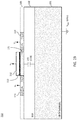
- FIG. 5A shows an embodiment of the present disclosure referred to as Through BOX Contact, TBC, where a resistive coupling through the buried oxide (BOX) layer is formed by a through box contact that resistively couples a region of a circuit subjected to a high voltage to a surface region of the high resistivity silicon proximate the region of the circuit.
- the TBC contact according to the present disclosure holds a potential at said surface region of the high resistivity silicon substrate to a level substantially equal to the potential of said region of the circuit, thereby mitigating back gate effects affecting both the high voltage circuit and the low voltage circuit.
- FIG. 5B shows space charges formed around an interface region between the TBC contacts of FIG. 5A and the high resistivity substrate.
- FIG. 5C shows an exemplary embodiment of the TBC contact of the present disclosure where several such contacts are used to protect different regions of a circuit from back gate induced effects.
- FIG. 6A shows an embodiment of the present disclosure, where a TBC is used to resistively couple a region of a circuit subjected to a high voltage to an N-type implant formed in a region of a substrate, not necessarily a high-resistivity substrate, proximate the region of the circuit.
- the N-type implant creates a PN-junction and allows a difference in potential between the N-type implant and the (P-type) substrate that can be high, therefore isolating the region of the substrate proximate the region of the circuit from a potential of the substrate.
- the N-type implant holds a uniform potential at a level substantially equal to the potential of said region of the circuit, thereby mitigating back gate effects affecting both the high voltage circuit and the low voltage circuit.
- FIG. 6A shows two such implants, each formed under a different circuit, subjected to a different high voltage.
- FIG. 6B shows an embodiment of the present disclosure, similar to the embodiment depicted in FIG. 6A , where more than one TBC is used to resistively couple regions of a circuit subjected to high voltages to the N-type implant.
- FIG. 6C shows an embodiment of the present disclosure, similar to the embodiment depicted in FIG. 6A and FIG. 6B , where more than one N-type implant is formed in regions of the substrate proximate a same circuit, where TBC contacts are used to resistively couple different regions of the circuit to the more than one N-type implant.
- Such high voltages can be controlled directly or can be reduced to lower voltages for control by standard ICs.
- the high voltage coming from a battery or solar panel must be reduced from 10-100 V, to 1-3 V to be used by consumer electronics ICs.
- FIG. 1 shows cross sectional views of typical SOI MOSFET transistors fabricated on SOI, including a P-type MOSFET ( 110 ) and an N-type MOSFET ( 120 ).
- the P-type MOSFET ( 110 ) comprises a gate polysilicon region ( 112 ) which defines a gate channel ( 115 ), an insulating gate silicon oxide layer ( 113 ) which insulates region ( 112 ) from the gate channel ( 115 ), a source region ( 114 ) and a drain region ( 116 ).
- the N-type MOSFET ( 120 ) comprises similar regions ( 122 , 125 , 123 , 124 , 126 ) with the difference that the N and P type doping regions are reversed.
- the SOI MOSFETs comprise a layered structure, formed atop a substrate ( 101 ), and comprising a buried insulator layer ( 102 ), and a thin silicon layer ( 105 ) in which the active regions ( 114 , 115 , 116 ) and ( 124 , 125 , 126 ) are formed.
- the substrate ( 101 ) is a relatively high conductivity silicon (Si) substrate with a resistivity substantially lower than 1000 ⁇ cm, such as, for example, 10 ⁇ cm or lower
- Si conductivity silicon
- the buried insulator layer ( 102 ) also known as the buried oxide layer (BOX) is designed to provide electrical insulation between the active regions ( 114 , 115 , 116 , 124 , 125 , 126 ) formed in the thin silicon layer ( 105 ) and the substrate ( 101 ).
- BOX buried oxide layer
- a gate voltage, V G is applied to a gate electrode (connected to the gate polysilicon region ( 112 , 122 ) of a transistor ( 110 , 120 ), inducing an electric field in the gate oxide layer ( 113 , 123 ), thereby turning ON or OFF the transistor by inverting or accumulating the surface of the Si (gate) channel ( 115 , 125 ).
- the N-type SOI MOSFET ( 120 ) operates on positive voltages (e.g. positive V G causes the transistor to turn ON), and the P-type SOI MOSFET ( 110 ) operates on negative voltages (e.g. negative voltage V G causes the transistor to turn ON).
- transistors operating at such low V D S voltages are defined as “grounded transistors” since the lowest V D S voltage is approximately 0 V, or ground, GND.
- Such grounded transistors can, however, float up to much higher voltages as long as their V D S is maintained below their designed operating limit.
- the N-type MOSFET ( 120 ) shown in FIG. 1 can operate with its source, S ( 124 ), held at 70 V and its drain, D ( 126 ), held at 73 V.
- a gate voltage V G of between 70 and 73 V can be used.
- the P-type MOSFET ( 110 ) shown in FIG. 1 can also operate at 70 V, but in this case, the lowest voltage is applied to the drain, D ( 116 ), at 70 V, and the source, S ( 114 ), is at 73 V.
- a gate voltage V G of 73 V can turn OFF the P-type MOSFET ( 110 ) while a gate voltage V G of 70 V can turn it ON.
- transistors controlled by such high voltages comprising a high DC voltage offset, either positive or negative with respect to a reference voltage
- floating transistors In many cases, it can be desirable that both grounded transistors and floating transistors operate normally in a same IC on a same SOI substrate. It follows that according to the various embodiments of the present disclosure, methods and devices for operating grounded transistors and floating transistors in a same IC on a same SOI substrate are presented.
- the transistors work just as they do without high voltage offset, i.e., they can be used in digital or analog circuit.
- the high voltage offset has several side effects that must be considered and dealt with. The largest such side effect, and the one of primary concern for the present invention, is that the high voltages induce electric fields in the buried oxide layer, BOX ( 102 ), of FIG. 1 , and thereby couple (e.g. capacitively) to the substrate ( 101 ).
- the substrate ( 101 ) can effectively operate like a parasitic gate electrode, commonly called a “back gate”, which can affect the overall performance of the MOSFET.
- effects of such back gate may include, for example, impact on a leakage current of the MOSFET, shift of a threshold voltage of the MOSFET, and/or turning ON or OFF the so-called “back channel” of a thin film MOSFET transistor (e.g. transistors ( 110 , 120 ) of FIG. 1 , thin film being reference to the relatively thin Si layer ( 105 )), the back-channel being a region (e.g. 280 of FIG. 2A , later described) of the thin film transistor gate channel (e.g. ( 115 , 125 ) of FIGS. 1 and 2A ) proximate the buried oxide layer (e.g. 102 of FIG. 1 ).
- a thin film MOSFET transistor e.g. transistors ( 110 , 120 ) of FIG. 1 , thin film being reference to the relatively thin Si layer
- FIG. 2A shows the back gate effect.
- the substrate is held at a voltage V SUB equal to ground, GND, (for example, by being grounded in a package, and having a relatively conductive substrate ( 101 ) material) while the transistors are at a DC offset voltage of 15 V.
- V SUB ground
- GND relatively conductive substrate
- the grounded substrate ( 101 ) is at a voltage V SUB which is 18 V negative with respect to the source, S ( 114 ), of the PMOS transistor ( 110 ), which voltage can therefore induce changes to the conductivity of the back channel and therefore induce changes in the current seen between S ( 114 ) and the D ( 116 ) that may not be controllable by the G ( 112 ).
- V SUB voltage negative with respect to the source, S ( 114 ), of the PMOS transistor ( 110 ), which voltage can therefore induce changes to the conductivity of the back channel and therefore induce changes in the current seen between S ( 114 ) and the D ( 116 ) that may not be controllable by the G ( 112 ).
- the turning ON of the back channel responsive to the voltage V SUB may further be a function of the BOX layer ( 102 ) thickness and a back channel doping concentration of the PMOS transistor ( 110 ).
- the back channel PMOSFET controlled by the substrate ( 101 ) voltage VSUB, can either exhibit back gate induced leakage currents or outright turn ON.
- every PMOSFET (formed on the same layered structure as the PMOSFET ( 110 )) operating at a high positive offset voltage can exhibit a similar leakage current.
- the source region, S ( 114 ), and the drain region, D ( 116 ) are the same for both the top transistors controlled by their gate voltages (e.g. VG) and the backside transistors controlled by their back gate voltages (e.g. VSUB), the back channel leakage current ISDB flows into a topside circuit comprising the topside transistors, causing numerous issues.
- Such topside circuit is typically designed based on an OFF PMOSFET having OFF IDS currents of typically less than nanoamps of leakage current.
- back gate effect can induce back channel IDS currents (e.g. ISDB) that are both uncontrolled by the topside circuit and possibly unpredictable.
- back channel IDS currents in the back channel transistors can be orders of magnitude more current than the anticipated sub nanoamps of normal leakage current.
- the back channel IDS currents are effectively parasitic currents that can upset operation or disable the designed topside circuit.
- an NMOSFET transistor e.g. ( 110 ) of FIG. 1
- a source e.g. ( 124 ) of FIG. 1
- This can occur, for example, if the NMSOFET (circuit) is floated to ⁇ 15 V, thereby making the substrate 15 V positive with respect to the source of the floating NMOSFET.
- back channel leakage can also occur, for example, if positive floating (high) voltages from the top side (floating) NMOSFET transistors (circuit) are coupled to the substrate ( 101 ) and then spread under grounded (low voltage) NMOSFETs formed in a same layered structure as the floating NMOSFET transistors, as discussed below.
- low resistivity silicon, Si, substrate is defined as a silicon substrate with a resistivity substantially lower than 1000 ⁇ cm, such as, for example, 10 ⁇ cm or lower.
- MOSFETs e.g. circuit using MOSFETs
- FIG. 2B shows a relatively high resistivity silicon substrate as shown in FIG. 2B .
- high resistivity silicon, HR-Si, substrate is defined as a silicon substrate with a resistivity substantially higher than 10 ⁇ cm, such as, for example, approximately 1000 ⁇ cm or larger. Usage of such HR-Si substrate in a layered SOI structure can further influence coupling of floating voltages to floating and grounded transistors formed in the layered SOI structure, which can further complicate the back channel effects.
- a person skilled in the art would know how to choose substrate ( 101 ) resistivity according to a specific application requirement (e.g., high voltage level). The higher the resistivity, the higher the breakdown voltage (e.g., according to a square root relationship) and therefore the higher voltage that can be applied to a circuit formed above.
- the capacitor ( 215 ) represents a capacitive coupling between the PMOSFET transistor ( 110 ) and the substrate ( 101 ).
- the top plate, bottom plate and corresponding in-between region of the insulating layer ( 102 ) forming the capacitor ( 215 ).
- larger structures of the PMOSFET ( 110 ) can create a larger capacitor ( 215 ) as such larger structure can have larger surfaces (areas) and therefore can create a larger top plate.
- the surface (area) of the bottom plate follows the surface of the top plate.
- the capacitor e.g., equivalent capacitance
- the capacitor can be a function of a surface of the silicon used in a top device, it follows that a plurality of neighboring PMOSFET transistors, similar to the PMOS transistor ( 110 ), formed on the same layered SOI structure depicted in, for example, FIG. 1 , can form a larger top plate and therefore a larger capacitor ( 215 ).
- silicon used in a top circuit can contribute to a size of the capacitor ( 215 ).
- a similar capacitor can be associated to the NMOSFET ( 120 ) of FIG. 1 , formed in a similar fashion as capacitor ( 215 ) associated to the PMOSFET ( 110 ), whose capacitance can also be a function of a total surface of a top circuit formed in the silicon layer ( 105 ).
- the SOI PMOSFET ( 210 ) comprises a layered structure, formed atop a HR-Si substrate ( 201 ), and comprising a buried insulator (BOX) layer ( 102 ), and a thin silicon layer ( 105 ) in which the active source, gate, drain regions ( 114 , 115 , 116 ) are formed.
- BOX buried insulator
- the buried insulator layer ( 102 ) is designed to provide electrical insulation between the active regions ( 114 , 115 , 116 ) formed in the thin silicon layer ( 105 ) and the HR-Si substrate ( 201 ).
- the HR-Si substrate ( 201 ) may have a substrate conductivity at a substrate region proximate the BOX layer ( 102 ) (e.g. top surface of the substrate ( 201 ) as shown in FIG. 2B ) which is different from a substrate conductivity at a backside of the substrate ( 201 ) (e.g.
- the top surface of the HR-Si substrate ( 201 ) can therefore float to a potential substantially different from a potential of the back of the HR-Si substrate ( 201 ), the potential at the top surface of the HR-Si effectively being the back gate potential of the back channel FET.
- FIG. 2C shows a cross sectional view of an SOI PMOSFET transistor ( 210 c ) comprising a layered structure similar to one described above with relation to FIG. 2B , with an added trap rich (TR) layer ( 203 ).
- TR trap rich
- a person skilled in the art would know of the added benefits that such TR layer ( 203 ) may provide in SOI devices used in RF applications and may therefore decide to optionally form such layer atop the HR Si substrate ( 201 ) given various methods and techniques known in the art.
- the various embodiments according to the present disclosure may equally apply to SOI MOSFETs formed on layered structures with or without a trap rich layer ( 203 ).
- HR-Si substrates not only can the back channel gate voltage float to uncontrolled levels, it can also float to different levels across an area of any given IC. This means there may be multiple regions of various and different back channel gate voltages, further complicating use of HR-Si substrates for high voltage circuit on SOI.
- FIG. 3 shows a cross sectional view of a floating PMOSFET transistor ( 210 ) and a grounded NMOSFET transistor ( 220 ) fabricated in a layered SOI structure atop a HR-Si substrate ( 201 ) as discussed above with reference to FIG. 2B .
- Resistive couplings between top regions ( 365 , 375 ) of the HR-Si substrate ( 201 ) proximate the transistors ( 210 , 220 ) which define corresponding back gate voltages and the bottom region of the HR-Si (at VSUB potential) are shown as equivalent resistance RSUB 1 ( 340 ) and equivalent distributed resistance RSUB 2 ( 345 ), whereas coupling of potentials at the top regions ( 365 , 375 ) to the transistors ( 210 , 220 ) by way of capacitive coupling through the insulating BOX layer ( 102 ) is shown as capacitors ( 315 , 325 ). As shown in FIG.
- the equivalent distributed resistance RSUB 2 can be formed by a distribution of a number of elemental resistive paths in parallel, each elemental resistive path being defined by the resistivity of the substrate and a length of the path along the substrate ( 201 ).
- the cross sectional view depicted in FIG. 3 is not to scale, as transistors ( 210 ) and ( 220 ) may be at a relative distance of, for example, several 10's to 100 micrometers, so several orders of magnitude larger when compared to sizes of the structures of the transistors ( 210 , 220 ) as shown in the FIG. 3 .
- the capacitor ( 315 ) represents a capacitive coupling between the PMOSFET transistor ( 210 ) and the HR-Si substrate ( 201 ) through the insulating layer ( 102 ).
- the top plate, bottom plate and corresponding in-between region of the insulating layer form the capacitor ( 315 ).
- larger structures of the PMOSFET ( 210 ) can create a larger capacitor ( 315 ) as such larger structure can have larger surfaces (areas) and therefore can create a larger top plate.
- the surface (area) of the bottom plate follows the surface of the top plate.
- the capacitor can be a function of a surface of the silicon used in a top device, it follows that a plurality of neighboring PMOSFET transistors, similar to the PMOS transistor ( 210 ), formed on the same layered SOI structure depicted in FIG. 3 , can form a larger top plate and therefore a larger capacitor ( 315 ).
- Capacitor ( 325 ) associated to the NMOSFET ( 220 ) is formed in a similar fashion and can also be a function of a total surface of a top circuit formed in the silicon layer ( 105 ).
- a value of the equivalent resistance R SUB1 can be in the order of about 30 M ⁇ , and a value of the equivalent distributed resistance R SUB2 can be in the order of about 250 KO.
- a relative distance between the two top regions ( 365 , 375 ) can be of a same order of magnitude as a thickness of the HR-Si substrate ( 201 )
- the value of the equivalent distributed resistance R SUB2 is substantially lower than the value of the equivalent resistance R SUB1 due to mainly a current spreading provided by a larger conduction cross section between a top region (e.g. 375 ) and the bottom region of the substrate ( 201 ) as compared to a current spreading provided by a conduction cross section between the top region ( 365 ) and the top region ( 375 ).
- a larger conduction cross section between two regions of the substrate ( 201 ) is equivalent to a larger number of elemental resistive paths in parallel, thereby reducing the equivalent resistance value, each elemental resistive path being defined by the resistivity of the substrate and a distance between the two regions.
- the PMOSFET ( 210 ) of FIG. 3 which is near the grounded NMOSFET ( 220 ), floats to 15 V
- the PMOSFET ( 210 ) (which can be part of a circuit) couples its 15 V floating voltage to the HR-Si substrate ( 201 ), thereby raising a potential at the region ( 365 ) up toward 15 V.
- this higher substrate potential can spread (resistively) along the surface of the HR-Si substrate ( 201 ) from the region ( 365 ) to the region ( 375 ) under the NMOSFET ( 220 ), thereby creating a positive back gate voltage under the NMOSFET ( 220 ), which in turn creates back channel leakage currents in the NMOSFET ( 220 ) as discussed above.
- a person skilled in the art would realize that the positive back gate voltage created in the region ( 375 ) under the NMOSFET ( 220 ) can be dependent on a relative distance of the two transistor devices ( 210 , 220 ).
- the resistive spreading of the potential at the region ( 365 ) to the region ( 375 ) can cause a reduction of the back gate voltage of the NMOSFET ( 220 ) formed in the region ( 375 ), and thereby causing a reduction in a corresponding parasitic back channel leakage of the NMOSFET transistor ( 220 ).
- floating circuit e.g. positive high voltages
- back channel effect related leakage in both the PMOSFET transistors and in the NMOSFET transistors of the circuit.
- back channel effects can be localized and dependent on layout geometries.
- FIG. 3 serves as a basis for describing issues related to floating circuits and therefore should not be considered as limiting the scope of the present disclosure.
- a NMOSFET transistor floating to a high voltage can induce a positive back gate voltage on a neighbor floating and/or grounded NMOSFET transistor.
- a large area of floating transistors can induce a higher voltage than a smaller area due to the well-understood nature of capacitive coupling, as the larger area can create a larger capacitor (e.g. 315 ) than a smaller area.
- the various embodiments according to the present disclosure attempt to reduce the above described back channel effects by controlling HR-Si substrate potentials under floating and/or grounded devices (e.g. at regions ( 365 , 375 ) of FIG. 3 ) formed in a layered SOI structure (e.g. FIG. 2B and FIG. 3 ).
- Each embodiment according to the present disclosure comprises structures that control the substrate potentials below high and low voltage regions (e.g. regions below floating and grounded devices, such as regions ( 365 , 375 ) of FIG. 3 ) of an SOI IC.
- the region can be a region associated to one device (NMOSFET, PMOSFET) or to a plurality of devices combined to form a functional circuit.
- NMOSFET NMOSFET
- PMOSFET PMOSFET
- Several such functional circuits may be formed in different regions of an SOI IC and operate at different voltages, such as, for example, one circuit operating at a high voltage and another circuit operating at a low voltage.
- back gate induced parasitic leakage currents may or may not pose operation issues of the circuit and/or device. Accordingly, the various embodiments of the present disclosure may be used to control surface potentials of the substrate under sub-regions of a circuit where corresponding devices need to be protected against back gate related effects.
- FIG. 4A shows a simplified cross sectional view of a high voltage (HV) circuit ( 410 ) and a low voltage (LV) circuit formed in a layered SOI structure using a HR-Si substrate ( 201 ).
- the HV circuit ( 410 ) can be formed by a plurality of floating devices, such as the device ( 210 ) of FIG. 3 , interconnected with passive components (e.g. capacitors, resistors) to provide a desired functionality of the HV circuit.
- the LV circuit ( 420 ) can be formed by a plurality of grounded devices, such as the device ( 220 ) of FIG. 3 , interconnected with passive components (e.g. capacitors, resistors) to provide a desired functionality of the LV circuit.
- top plates of each of the capacitors ( 315 ) and ( 325 ) can be formed by a combined surface of silicon structures in the silicon layer ( 105 ) that form each of the HV and LV circuits.
- the HV circuit ( 410 ) can operate from a high DC voltage, but can also operate from a switching high voltage, as described in the above referenced U.S. application Ser. No. 14/661,848 entitled “Level Shifter”, which is herein incorporated by reference in its entirety. It follows that the various embodiments according to the present disclosure reduce the above described back channel effects in consideration of both time dependent and DC, i.e., equilibrium steady state potentials at the surface regions ( 465 , 475 ) of the HR-Si substrate ( 201 ) under the HV ( 410 ) and LV ( 420 ) circuits.
- an optional trap rich, TR, layer ( 203 ) (as shown in FIG. 4C ) can provide a higher isolation between the surface regions ( 465 ) and ( 475 ).
- substrate ( 201 ) potentials at regions ( 465 ) and ( 475 ) will approximately track the potentials of the HV ( 410 ) circuit and LV ( 420 ) circuit respectively.
- Capacitive Coupling through BOX herein referred to as Capacitive Coupling through BOX, “CCB”, the back gate effect is controlled, during a transition time of a high voltage from its low level to its high level, by designing capacitive coupling ( 315 ) from a first region ( 410 ) of the upper Si film ( 105 ) being subjected to a first voltage (e.g. a switching high voltage, transitions between a low level and a high level) to the substrate ( 201 ) and from a second region ( 420 ) of the upper Si film ( 105 ) being subjected to a second voltage (e.g.
- a first voltage e.g. a switching high voltage, transitions between a low level and a high level
- the substrate ( 201 ) such that the substrate region ( 465 ) formed in the Si film ( 105 ) under the first region ( 410 ), and the substrate region ( 475 ) formed in the Si film ( 105 ) under the second region ( 420 ) of the Si film ( 105 ), are substantially equal to the respective voltages of the film regions ( 410 , 420 ).
- This mechanism is further depicted in FIG. 4B , where the capacitive coupling ( 315 ) of FIG. 4A is modified by adding a region ( 410 b ), comprising silicon, metal or a combination thereof, to the region ( 410 ), to provide the desired voltages in the regions ( 465 b ) and ( 475 ).
- the CCB method controls voltages, during a transition time of the first voltage (e.g., from a low level to a high level), at surface regions ( 465 , 475 ) of the substrate ( 101 ) under the Si film regions ( 410 , 420 ) by designing the capacitive couplings ( 315 , 325 ). Furthermore, the voltage at the surface regions ( 465 , 475 ) may be maintained even past the transition time if a period of the switching voltage is smaller than an RC time constant associated with the voltage at surface regions.
- each of the regions ( 410 ) and ( 420 ) can be comprised of a single PMOSFET or NMOSFET transistor, or circuit comprising such transistors interconnected through passive components which can also be formed in the Si film ( 105 ).
- a high voltage to which the region ( 410 ) can be subjected to can be either a DC voltage or a switching voltage.
- the CCB can provide a capacitive voltage divider between the HV circuit ( 410 / 410 b ) and the LV circuit ( 420 ) by way of corresponding capacitances ( 315 / 315 b , 325 ) and substrate resistances R SUB1 and R SUB2 .
- the HV circuit ( 410 ) of FIG. 4A is subjected to 15 V and the LV circuit ( 420 ) of FIG. 4A is subjected to 0V, then the size of the capacitors ( 315 , 325 ) of FIG.
- FIG. 4A under the HV/LV circuits ( 410 , 420 ) of FIG. 4A divide the voltages (15V, 0V) such that the substrate surface regions ( 465 , 475 ) are at potentials that can induce parasitic leakages in one or both of the HV and LV circuits ( 410 , 420 ).
- values of one or more of the capacitors ( 315 , 325 ) are modified such that the capacitive voltage divider between the HV and LV circuits ( 410 , 420 ) provides potentials at the substrate surface regions ( 465 , 475 ) that reduce, minimize or eliminate said induced parasitic leakages in both of the HV and LV circuits ( 410 , 420 ), as shown in the exemplary embodiment depicted in FIG. 4B .
- the area of the top plate of the capacitor ( 315 b ) is increased with respect to the area of the top plate of the capacitor ( 315 ) of FIG. 4A by the addition of the region ( 410 b ) adjacent to the region ( 410 ) that forms the HV circuit.
- This changes the capacitive voltage division described above to obtain the desired potentials at the surface regions ( 465 b , 475 ).
- the size of the capacitor (e.g. 465 ) can be adjusted, for example, by addition of silicon plates formed in the Si layer ( 105 ), or by addition of metal plates in areas adjacent to the BOX layer ( 102 ) created by first removing the Si layer ( 105 ).
- the region ( 410 b ) can comprise metal plates, silicon plates, a combination of metal and silicon plates and any other type of regions that can expand the top plate of capacitor.
- either one or both of the capacitances ( 315 , 325 ) of FIG. 4A can be adjusted based on the same concept so as to control the potentials at the regions ( 465 , 475 ) to mitigate the effects of the back gate.
- the HV CCB capacitor ( 315 ) has a value of 2 ⁇ and the LV CCB capacitor ( 325 ) has a value of 1 ⁇ , and that the high voltage is 15 V and the low voltage is 0 V.
- HV high voltage
- the regions comprising the bottom plates of capacitors ( 315 b , 325 ) initially assume the same potential as the respective top plates of capacitors ( 315 b , 325 ).
- the potential in the region ( 465 ) of the substrate underneath the HV circuit ( 410 ) may be higher than 10 V, and even approaching 15 V depending on a value of the resistance ( 340 ).
- both bottom plate regions will assume a same potential and eventually discharge to the potential the substrate is held at through V SUB (ground).
- the capacitive coupling mechanism can be effective as the potential of the substrate proximate the HV circuit can track the potential of the HV circuit, It should be noted that the same potential (equipotential) assumed by both bottom plate regions can be determined by the ratio of capacitors ( 315 b ) and ( 325 ). Since the HV CCB capacitor ( 315 b ) has 2 ⁇ the value of LV CCB capacitor ( 325 ), it has twice the influence on the equipotential value.
- the final equipotential value in this example is 10 volts, resulting in the potential difference across LV CCB capacitor ( 325 ) being 2 ⁇ the potential difference across the HV CCB capacitor ( 315 b ).
- Choice of substrate potentials is understood by a person skilled in the art to be determined by threshold voltages of transistors of the HV and LV circuits ( 410 , 420 ) and their sensitivity to back channel leakage. This non-limiting exemplary case simply shows how the substrate potential can be controlled by proper design of the current invention.
- the HV and LV circuits ( 410 , 420 ) can be designed to provide desired values of the capacitors ( 315 , 325 ), either effective capacitance values or ratios of the capacitances.
- a person skilled in the art would know of many methods and techniques suitable for determining values of the capacitors ( 315 , 325 ) so as to control voltages at the substrate surface regions ( 465 , 475 ) to mitigate the effects of the back gate.
- circuit regions (sub-circuits) or transistors of the circuits ( 410 , 420 ) to which the high voltage or low voltage are applied may form a contiguous region of the silicon layer ( 105 ) isolated from other regions of the silicon layer ( 105 ), similar to a silicon island.
- the CCB of the present disclosure can be used to control voltages at surface regions ( 465 , 475 ) of the substrate ( 201 ) under one or more silicon islands ( 410 , 420 ) held at different island voltages based on capacitive division of the island voltages, by adjusting the areas of the one or more islands which determine capacitance values used in the capacitive division of the island voltages.
- desired potentials at the substrate surface regions ( 465 , 475 ) can be maintained assuming that a period of the switching voltage is smaller than an RC time constant associated with a voltage at the substrate surface region ( 465 ). If said period is large enough or if the high voltage is a DC voltage, then the desired potential at the substrate surface region ( 465 ) may not be maintained as a corresponding voltage at the substrate surface region ( 465 ) discharges through the resistances ( 340 , 345 ).
- the CCB embodiment of the present disclosure may be characterized as transient control of the potentials of the substrate surface regions ( 465 , 475 ) with respect to the applied high and low voltages (to circuits ( 410 , 420 ) formed in the silicon layer ( 105 )).
- a static control of the potentials of the substrate surface regions ( 465 , 475 ) with respect to the applied high and low voltages is provided.
- Such static control according to the embodiment of the present disclosure is referred to as a Through BOX Contact, TBC, as shown in FIG. 5A , which uses through BOX contacts as known to person skilled in the art and described, for example, in the above referenced U.S. application Ser. No. 14/964,412 entitled “S-Contact for SOT”, which is herein incorporated by reference in its entirety.
- a through box contact, TBC ( 515 ) holds the potential at a surface of the substrate ( 565 ) under a region of the HV circuit ( 410 ) to a level substantially equal to the potential of the HV circuit ( 410 ) (that corresponds to the high voltage applied to the HV circuit).
- the TBC contact ( 515 ) is constructed in such a manner as to control a surface potential at the region ( 565 ) surrounding the TBC contact ( 515 ), while ensuring that any space charge region resulting from such contact is localized, thereby ensuring that the surface potential at the region ( 565 ) has a minimal effect on nearby regions (formed in the silicon layer ( 105 )) of the HV circuit ( 410 ).
- the region ( 565 ) does not cover the entire region under the HV circuit ( 410 ), but rather a localized region surrounding the TBC contact ( 515 ).
- TBC contacts can be used to maintain the substrate ( 201 ) in a spatially variable state with the potential difference between a transistor and local substrate maintained within acceptable limits, the transistor being a transistor sensitive to the back gate induced effects and the one or more TBC contacts being formed in close proximity of the transistor. Accordingly, TBC contacts can be selectively used for discrete transistors of the circuits ( 410 , 420 ), or regions of the circuits ( 410 , 420 ), that need protection against back gate induced effects.
- the TBC contact ( 515 , 525 ) biases the substrate ( 201 ) to near the potential applied to the TBC contact (at the circuit level) and when placed near a transistor, it can help keep a region of the substrate ( 201 ) under the transistor near the potential applied to the TBC contact ( 515 , 525 ).
- This effect can be seen in FIG. 5 , in which the center of the space charge where the TBC ( 515 , 525 ) makes contact is shown to be of lower density than those regions farther away from the center.
- the TBC contact ( 515 , 525 ) forms a critical DC current path which can source or sink charge and thereby reduce the space charge density near its contact point.
- the TBC contact ( 515 , 525 ) completes this current path along with substrate resistances (R SUB1 , R SUB2 ) as shown in FIG. 5B .
- substrate resistances R SUB1 , R SUB2
- FIG. 5B A person skilled in the art would understand that the resistance values are exemplary and can be designed to be substantially different to achieve different results. According to some exemplary embodiments of the present disclosure, such different results can be achieved by adding more or less TBC contacts to change an effective resistance.
- a non-ohmic contact e.g. ( 516 , 526 ) between the TBC ( 515 , 525 ) and the substrate ( 201 ) as described below.
- the TBC contact ( 515 , 525 ) is most effective close to its substrate contact ( 516 , 526 ), but at distances farther away, the space charge region is stronger and thereby susceptible to inducing back gate leakage to corresponding regions of the circuits ( 410 , 420 ).
- additional TBC contacts ( 515 , 525 ) can be designed to provide sufficient spatial screening to ensure all critical regions (circuits/transistors) in the HV circuit ( 410 ) are protected.
- TBC contacts can be used to resistively connect an island formed in the silicon layer ( 105 ) coupled to a high/low voltage to the substrate ( 201 ), through the insulating BOX layer ( 102 ).
- One or more such TBCs can be used for any given such island, and different islands formed in different (separate) regions of the silicon layer ( 105 ) can be fitted with one or more such TBCs.
- TBC biased negatively to the substrate potential injects electrons, creating a forward biased condition.
- injected electrons may diffuse substantial distances and thereby reduce the effective resistance of nearby reverse biased TBCs.
- Injected electrons can travel hundreds of micrometers in typical substrates and lower the potential at the substrate interface, even in regions with more positively biased TBC's, including a ring or array of TBCs.
- the TBC embodiment according to the present disclosure discussed above, with reference to FIGS. 5A-5C require a relatively high resistivity substrate ( 201 ) to create separate localized surface regions ( 565 , 575 ) of uniform and different potentials.
- a desired spatial screening can be achieved by usage of additional TBC contact such as, for example, to maintain larger localized surface regions.
- an N-type implant can be formed in the substrate to extend to surface regions of the substrate proximate circuitries to be protected, as shown in FIG. 6A .
- FIG. 6A shows an embodiment of the present disclosure, where a TBC ( 515 , 525 ) is used to resistively couple a region of a circuit ( 410 , 420 ) subjected to a high voltage to an N-type implant ( 665 , 675 ) formed in a region of a substrate ( 301 ), not necessarily a high-resistivity substrate, proximate the region of the circuit ( 410 , 420 ).
- the N-type implant ( 665 , 675 ) creates a PN-junction and allows a difference in potential between the N-type implant ( 665 , 675 ) and the (P-type) substrate ( 301 ) that can be high (e.g.
- FIG. 6A shows two such implants ( 665 ) and ( 675 ), each formed under a different circuit, ( 410 ) and ( 420 ) respectively, subjected to a different high voltage. Contrary to the TBC based embodiments of the present disclosure depicted in FIGS.
- the present TBC based embodiment does not require a high resistivity substrate, as the substrate ( 301 ) of FIG. 6A can be either a low resistivity or a high resistivity substrate (each with or without a TR layer).
- the substrate ( 301 ) of FIG. 6A can be either a low resistivity or a high resistivity substrate (each with or without a TR layer).
- several TBC contacts ( 515 , 525 ) can be used to resistively couple different regions of a same circuit ( 410 , 420 ) to a same N-type implant ( 665 , 675 ).
- a person skilled in the art would find other implementations examples, such as, for example, depicted in FIG. 6C , and therefore the exemplary embodiments presented herein should not be considered as limiting the scope of what the applicant considers to be the invention.
- MOSFET technically refers to metal-oxide-semiconductors; another synonym for MOSFET is “MISFET”, for metal-insulator-semiconductor FET.
- MOSFET has become a common label for most types of insulated-gate FETs (“IGFETs”).
- IGFETs insulated-gate FETs
- Voltage levels may be adjusted or voltage and/or logic signal polarities reversed depending on a particular specification and/or implementing technology (e.g., NMOS, PMOS, or CMOS, and enhancement mode or depletion mode transistor devices).
- Component voltage, current, and power handling capabilities may be adapted as needed, for example, by adjusting device sizes, serially “stacking” components (particularly FETs) to withstand greater voltages, and/or using multiple components in parallel to handle greater currents.
- Additional circuit components may be added to enhance the capabilities of the disclosed circuits and/or to provide additional functional without significantly altering the functionality of the disclosed circuits.
Landscapes
- Thin Film Transistor (AREA)
- Physics & Mathematics (AREA)
- Geometry (AREA)
- Semiconductor Integrated Circuits (AREA)
- Metal-Oxide And Bipolar Metal-Oxide Semiconductor Integrated Circuits (AREA)
- Emergency Protection Circuit Devices (AREA)
Abstract
Description
Claims (15)
Priority Applications (1)
| Application Number | Priority Date | Filing Date | Title |
|---|---|---|---|
| US16/422,648 US10770480B2 (en) | 2016-12-20 | 2019-05-24 | Systems, methods, and apparatus for enabling high voltage circuits |
Applications Claiming Priority (3)
| Application Number | Priority Date | Filing Date | Title |
|---|---|---|---|
| US15/385,618 US9847348B1 (en) | 2016-12-20 | 2016-12-20 | Systems, methods and apparatus for enabling high voltage circuits |
| PCT/US2017/059106 WO2018118224A1 (en) | 2016-12-20 | 2017-10-30 | Systems, methods and apparatus for enabling high voltage circuits |
| US16/422,648 US10770480B2 (en) | 2016-12-20 | 2019-05-24 | Systems, methods, and apparatus for enabling high voltage circuits |
Related Parent Applications (1)
| Application Number | Title | Priority Date | Filing Date |
|---|---|---|---|
| PCT/US2017/059106 Continuation WO2018118224A1 (en) | 2016-12-20 | 2017-10-30 | Systems, methods and apparatus for enabling high voltage circuits |
Publications (2)
| Publication Number | Publication Date |
|---|---|
| US20190280011A1 US20190280011A1 (en) | 2019-09-12 |
| US10770480B2 true US10770480B2 (en) | 2020-09-08 |
Family
ID=60629264
Family Applications (3)
| Application Number | Title | Priority Date | Filing Date |
|---|---|---|---|
| US15/385,618 Active US9847348B1 (en) | 2016-12-20 | 2016-12-20 | Systems, methods and apparatus for enabling high voltage circuits |
| US15/799,983 Active US10147740B2 (en) | 2016-12-20 | 2017-10-31 | Methods and structures for reducing back gate effect in a semiconductor device |
| US16/422,648 Active US10770480B2 (en) | 2016-12-20 | 2019-05-24 | Systems, methods, and apparatus for enabling high voltage circuits |
Family Applications Before (2)
| Application Number | Title | Priority Date | Filing Date |
|---|---|---|---|
| US15/385,618 Active US9847348B1 (en) | 2016-12-20 | 2016-12-20 | Systems, methods and apparatus for enabling high voltage circuits |
| US15/799,983 Active US10147740B2 (en) | 2016-12-20 | 2017-10-31 | Methods and structures for reducing back gate effect in a semiconductor device |
Country Status (4)
| Country | Link |
|---|---|
| US (3) | US9847348B1 (en) |
| CN (2) | CN116387323A (en) |
| TW (2) | TWI733939B (en) |
| WO (1) | WO2018118224A1 (en) |
Families Citing this family (10)
| Publication number | Priority date | Publication date | Assignee | Title |
|---|---|---|---|---|
| US9912327B2 (en) | 2015-03-18 | 2018-03-06 | Peregrine Semiconductor Corporation | Dead time control circuit for a level shifter |
| US9837412B2 (en) | 2015-12-09 | 2017-12-05 | Peregrine Semiconductor Corporation | S-contact for SOI |
| DE102016218207A1 (en) * | 2016-09-22 | 2018-03-22 | Robert Bosch Gmbh | Electronic assembly, in particular an electronic power module for hybrid vehicles or electric vehicles |
| US9847348B1 (en) | 2016-12-20 | 2017-12-19 | Peregrine Semiconductor Corporation | Systems, methods and apparatus for enabling high voltage circuits |
| US10276371B2 (en) | 2017-05-19 | 2019-04-30 | Psemi Corporation | Managed substrate effects for stabilized SOI FETs |
| US10672726B2 (en) | 2017-05-19 | 2020-06-02 | Psemi Corporation | Transient stabilized SOI FETs |
| US10658386B2 (en) | 2018-07-19 | 2020-05-19 | Psemi Corporation | Thermal extraction of single layer transfer integrated circuits |
| CN113224010B (en) * | 2020-01-21 | 2025-06-03 | 世界先进积体电路股份有限公司 | Semiconductor structure |
| CN112259526B (en) * | 2020-10-19 | 2022-08-02 | 海光信息技术股份有限公司 | Integrated circuit and electronic device |
| CN116266557B (en) * | 2021-12-17 | 2026-01-30 | 联华电子股份有限公司 | Semiconductor Components and Their Fabrication Methods |
Citations (41)
| Publication number | Priority date | Publication date | Assignee | Title |
|---|---|---|---|---|
| US5416043A (en) | 1993-07-12 | 1995-05-16 | Peregrine Semiconductor Corporation | Minimum charge FET fabricated on an ultrathin silicon on sapphire wafer |
| US6130458A (en) | 1996-03-28 | 2000-10-10 | Kabushiki Kaisha Toshiba | Power IC having SOI structure |
| US20020125921A1 (en) | 2000-11-02 | 2002-09-12 | Van Wershoven Loesje Maria Jacoba | Integrated circuit with output drivers |
| US20040129977A1 (en) | 2002-12-20 | 2004-07-08 | Nec Electronics Corporation | SOI substrate and semiconductor integrated circuit device |
| US20050156631A1 (en) | 2004-01-15 | 2005-07-21 | Via Technologies, Inc. | Level shifter |
| US20060087470A1 (en) | 2004-10-19 | 2006-04-27 | Edgar Abdoulin | High voltage level shifting by capacitive coupling |
| US7199617B1 (en) | 2004-11-12 | 2007-04-03 | Intel Corporation | Level shifter |
| US20070159150A1 (en) | 2004-01-28 | 2007-07-12 | Kyoichi Hosokawa | Switching power supply device and a semiconductor integrated circuit |
| US7414289B2 (en) | 2006-07-17 | 2008-08-19 | Advanced Micro Devices, Inc. | SOI Device with charging protection and methods of making same |
| US20080224755A1 (en) | 2007-03-12 | 2008-09-18 | Seiko Epson Corporation | Level-shift circuit, electro-optical device, and level shift method |
| US20090206817A1 (en) | 2008-02-15 | 2009-08-20 | Avago Technologies Ecbu (Singapore) Ple. Ltd. | High Voltage Drive Circuit Employing Capacitive Signal Coupling and Associated Devices and Methods |
| WO2009108391A1 (en) | 2008-02-28 | 2009-09-03 | Peregrine Semiconductor Corporation | Method and apparatus for use in digitally tuning a capacitor in an integrated circuit device |
| US20090283854A1 (en) | 2008-05-19 | 2009-11-19 | Levy Max G | Design Structure and Method for Buried Inductors for Ultra-High Resistivity Wafers for SOI/RF SIGE Applications |
| US20100244934A1 (en) | 2009-03-26 | 2010-09-30 | International Business Machines Corporation | Soi radio frequency switch with enhanced electrical isolation |
| US8049532B1 (en) | 2010-06-25 | 2011-11-01 | Altera Corporation | Level shifter circuit with a thin gate oxide transistor |
| US8048753B2 (en) | 2009-06-12 | 2011-11-01 | Globalfoundries Inc. | Charging protection device |
| US20110278581A1 (en) * | 2010-05-17 | 2011-11-17 | Renesas Electronics Corporation | Semiconductor device and manufacturing method thereof |
| US8169108B2 (en) | 2004-06-03 | 2012-05-01 | Silicon Laboratories Inc. | Capacitive isolator |
| US20120313173A1 (en) | 2011-06-07 | 2012-12-13 | Rf Micro Devices, Inc. | Method for isolating rf functional blocks on silicon-on-insulator (soi) substrates |
| US8593128B2 (en) | 2009-12-23 | 2013-11-26 | R2 Semiconductor, Inc. | Stacked NMOS DC-to-DC power conversion |
| US20130314065A1 (en) | 2012-05-22 | 2013-11-28 | Integrated Solutions Technology Inc. | Load-adaptive power generator |
| EP2731269A1 (en) | 2012-11-07 | 2014-05-14 | SEMIKRON Elektronik GmbH & Co. KG | Actuation switch with transmission circuit and method for operating |
| US20140169038A1 (en) | 2012-12-13 | 2014-06-19 | Texas Instruments Incorporated | Digital isolator |
| US20140191322A1 (en) | 2013-01-10 | 2014-07-10 | International Business Machines Corporation | Silicon-on-insulator heat sink |
| EP2787642A2 (en) | 2013-04-03 | 2014-10-08 | Nxp B.V. | Capacitive level shifter devices, methods and systems |
| US20140333365A1 (en) | 2013-05-10 | 2014-11-13 | Semiconductor Energy Laboratory Co., Ltd. | Semiconductor device |
| US20150206964A1 (en) | 2014-01-22 | 2015-07-23 | Taiwan Semiconductor Manufacturing Co., Ltd. | Semiconductor device structure with metal ring on silicon-on-insulator (soi) substrate |
| US20150229307A1 (en) | 2014-02-13 | 2015-08-13 | Sayeed Ahmed Badrudduza | Level Shifter With Improved Operation |
| US20160035899A1 (en) | 2014-07-30 | 2016-02-04 | Qualcomm Incorporated | Biasing a silicon-on-insulator (soi) substrate to enhance a depletion region |
| US20160141228A1 (en) * | 2014-11-14 | 2016-05-19 | International Business Machines Corporation | Device connection through a buried oxide layer in a silicon on insulator wafer |
| US20160164413A1 (en) | 2013-08-01 | 2016-06-09 | Hitachi, Ltd. | Semiconductor device and power conversion device |
| US20160190231A1 (en) | 2014-12-27 | 2016-06-30 | Kabushiki Kaisha Toshiba | Semiconductor switch |
| US20160277012A1 (en) | 2015-03-18 | 2016-09-22 | Peregrine Semiconductor Corporation | Dead Time Control |
| US20160277008A1 (en) | 2015-03-18 | 2016-09-22 | Peregrine Semiconductor Corporation | Level Shifter |
| US9472512B1 (en) | 2015-10-14 | 2016-10-18 | Globalfoundries Singapore Pte. Ltd. | Integrated circuits with contacts through a buried oxide layer and methods of producing the same |
| US20160336344A1 (en) | 2015-05-12 | 2016-11-17 | Skyworks Solutions, Inc. | Silicon-on-insulator devices having contact layer |
| US20170170177A1 (en) | 2015-12-09 | 2017-06-15 | Peregrine Semiconductor Corporation | S-Contact for SOI |
| WO2017123269A1 (en) | 2016-01-11 | 2017-07-20 | Peregrine Semiconductor Corporation | Dead time control |
| US9847348B1 (en) | 2016-12-20 | 2017-12-19 | Peregrine Semiconductor Corporation | Systems, methods and apparatus for enabling high voltage circuits |
| US20180337043A1 (en) | 2017-05-19 | 2018-11-22 | Psemi Corporation | Managed Substrate Effects for Stabilized SOI FETs |
| US10672726B2 (en) | 2017-05-19 | 2020-06-02 | Psemi Corporation | Transient stabilized SOI FETs |
Family Cites Families (5)
| Publication number | Priority date | Publication date | Assignee | Title |
|---|---|---|---|---|
| JP4282388B2 (en) * | 2003-06-30 | 2009-06-17 | 株式会社東芝 | Semiconductor memory device |
| US6960802B1 (en) * | 2003-09-16 | 2005-11-01 | Advanced Micro Devices, Inc. | Performing passive voltage contrast on a silicon on insulator semiconductor device |
| JP4675813B2 (en) * | 2006-03-31 | 2011-04-27 | Okiセミコンダクタ株式会社 | Semiconductor memory device and manufacturing method thereof |
| US9105577B2 (en) * | 2012-02-16 | 2015-08-11 | International Business Machines Corporation | MOSFET with work function adjusted metal backgate |
| US20150228714A1 (en) * | 2014-02-13 | 2015-08-13 | Rfaxis, Inc. | Isolation methods for leakage, loss and non-linearity mitigation in radio-frequency integrated circuits on high-resistivity silicon-on-insulator substrates |
-
2016
- 2016-12-20 US US15/385,618 patent/US9847348B1/en active Active
-
2017
- 2017-10-30 WO PCT/US2017/059106 patent/WO2018118224A1/en not_active Ceased
- 2017-10-30 CN CN202310379311.2A patent/CN116387323A/en active Pending
- 2017-10-30 CN CN201780078779.0A patent/CN110088892B/en active Active
- 2017-10-31 US US15/799,983 patent/US10147740B2/en active Active
- 2017-11-06 TW TW106138296A patent/TWI733939B/en active
- 2017-11-06 TW TW110123663A patent/TWI819325B/en active
-
2019
- 2019-05-24 US US16/422,648 patent/US10770480B2/en active Active
Patent Citations (54)
| Publication number | Priority date | Publication date | Assignee | Title |
|---|---|---|---|---|
| US5600169A (en) | 1993-07-12 | 1997-02-04 | Peregrine Semiconductor Corporation | Minimum charge FET fabricated on an ultrathin silicon on sapphire wafer |
| US5416043A (en) | 1993-07-12 | 1995-05-16 | Peregrine Semiconductor Corporation | Minimum charge FET fabricated on an ultrathin silicon on sapphire wafer |
| US6130458A (en) | 1996-03-28 | 2000-10-10 | Kabushiki Kaisha Toshiba | Power IC having SOI structure |
| US20020125921A1 (en) | 2000-11-02 | 2002-09-12 | Van Wershoven Loesje Maria Jacoba | Integrated circuit with output drivers |
| US20040129977A1 (en) | 2002-12-20 | 2004-07-08 | Nec Electronics Corporation | SOI substrate and semiconductor integrated circuit device |
| US20050156631A1 (en) | 2004-01-15 | 2005-07-21 | Via Technologies, Inc. | Level shifter |
| US20070159150A1 (en) | 2004-01-28 | 2007-07-12 | Kyoichi Hosokawa | Switching power supply device and a semiconductor integrated circuit |
| US8169108B2 (en) | 2004-06-03 | 2012-05-01 | Silicon Laboratories Inc. | Capacitive isolator |
| US20060087470A1 (en) | 2004-10-19 | 2006-04-27 | Edgar Abdoulin | High voltage level shifting by capacitive coupling |
| US7199617B1 (en) | 2004-11-12 | 2007-04-03 | Intel Corporation | Level shifter |
| US7414289B2 (en) | 2006-07-17 | 2008-08-19 | Advanced Micro Devices, Inc. | SOI Device with charging protection and methods of making same |
| US20080224755A1 (en) | 2007-03-12 | 2008-09-18 | Seiko Epson Corporation | Level-shift circuit, electro-optical device, and level shift method |
| US20090206817A1 (en) | 2008-02-15 | 2009-08-20 | Avago Technologies Ecbu (Singapore) Ple. Ltd. | High Voltage Drive Circuit Employing Capacitive Signal Coupling and Associated Devices and Methods |
| WO2009108391A1 (en) | 2008-02-28 | 2009-09-03 | Peregrine Semiconductor Corporation | Method and apparatus for use in digitally tuning a capacitor in an integrated circuit device |
| US9197194B2 (en) | 2008-02-28 | 2015-11-24 | Peregrine Semiconductor Corporation | Methods and apparatuses for use in tuning reactance in a circuit device |
| US20090283854A1 (en) | 2008-05-19 | 2009-11-19 | Levy Max G | Design Structure and Method for Buried Inductors for Ultra-High Resistivity Wafers for SOI/RF SIGE Applications |
| US20100244934A1 (en) | 2009-03-26 | 2010-09-30 | International Business Machines Corporation | Soi radio frequency switch with enhanced electrical isolation |
| US8048753B2 (en) | 2009-06-12 | 2011-11-01 | Globalfoundries Inc. | Charging protection device |
| US8593128B2 (en) | 2009-12-23 | 2013-11-26 | R2 Semiconductor, Inc. | Stacked NMOS DC-to-DC power conversion |
| US20110278581A1 (en) * | 2010-05-17 | 2011-11-17 | Renesas Electronics Corporation | Semiconductor device and manufacturing method thereof |
| US8049532B1 (en) | 2010-06-25 | 2011-11-01 | Altera Corporation | Level shifter circuit with a thin gate oxide transistor |
| US20120313173A1 (en) | 2011-06-07 | 2012-12-13 | Rf Micro Devices, Inc. | Method for isolating rf functional blocks on silicon-on-insulator (soi) substrates |
| US20130314065A1 (en) | 2012-05-22 | 2013-11-28 | Integrated Solutions Technology Inc. | Load-adaptive power generator |
| EP2731269A1 (en) | 2012-11-07 | 2014-05-14 | SEMIKRON Elektronik GmbH & Co. KG | Actuation switch with transmission circuit and method for operating |
| US20140169038A1 (en) | 2012-12-13 | 2014-06-19 | Texas Instruments Incorporated | Digital isolator |
| US20140191322A1 (en) | 2013-01-10 | 2014-07-10 | International Business Machines Corporation | Silicon-on-insulator heat sink |
| EP2787642A2 (en) | 2013-04-03 | 2014-10-08 | Nxp B.V. | Capacitive level shifter devices, methods and systems |
| US20140333365A1 (en) | 2013-05-10 | 2014-11-13 | Semiconductor Energy Laboratory Co., Ltd. | Semiconductor device |
| US20160164413A1 (en) | 2013-08-01 | 2016-06-09 | Hitachi, Ltd. | Semiconductor device and power conversion device |
| US20150206964A1 (en) | 2014-01-22 | 2015-07-23 | Taiwan Semiconductor Manufacturing Co., Ltd. | Semiconductor device structure with metal ring on silicon-on-insulator (soi) substrate |
| US20150229307A1 (en) | 2014-02-13 | 2015-08-13 | Sayeed Ahmed Badrudduza | Level Shifter With Improved Operation |
| US20160035899A1 (en) | 2014-07-30 | 2016-02-04 | Qualcomm Incorporated | Biasing a silicon-on-insulator (soi) substrate to enhance a depletion region |
| US20160141228A1 (en) * | 2014-11-14 | 2016-05-19 | International Business Machines Corporation | Device connection through a buried oxide layer in a silicon on insulator wafer |
| US20160190231A1 (en) | 2014-12-27 | 2016-06-30 | Kabushiki Kaisha Toshiba | Semiconductor switch |
| US20180175841A1 (en) | 2015-03-18 | 2018-06-21 | Psemi Corporation | Dead Time Control Circuit for a Level Shifter |
| US20160277008A1 (en) | 2015-03-18 | 2016-09-22 | Peregrine Semiconductor Corporation | Level Shifter |
| US9484897B2 (en) | 2015-03-18 | 2016-11-01 | Peregrine Semiconductor Corporation | Level shifter |
| US20170117883A1 (en) | 2015-03-18 | 2017-04-27 | Peregrine Semiconductor Corporation | Level Shifter |
| US20160277012A1 (en) | 2015-03-18 | 2016-09-22 | Peregrine Semiconductor Corporation | Dead Time Control |
| US20160336344A1 (en) | 2015-05-12 | 2016-11-17 | Skyworks Solutions, Inc. | Silicon-on-insulator devices having contact layer |
| US9472512B1 (en) | 2015-10-14 | 2016-10-18 | Globalfoundries Singapore Pte. Ltd. | Integrated circuits with contacts through a buried oxide layer and methods of producing the same |
| US9837412B2 (en) | 2015-12-09 | 2017-12-05 | Peregrine Semiconductor Corporation | S-contact for SOI |
| WO2017099871A1 (en) | 2015-12-09 | 2017-06-15 | Peregrine Semiconductor Corporation | S-contact for soi |
| US20180158822A1 (en) | 2015-12-09 | 2018-06-07 | Peregrine Semiconductor Corporation | S-Contact for SOI |
| US20170170177A1 (en) | 2015-12-09 | 2017-06-15 | Peregrine Semiconductor Corporation | S-Contact for SOI |
| WO2017123269A1 (en) | 2016-01-11 | 2017-07-20 | Peregrine Semiconductor Corporation | Dead time control |
| US9847348B1 (en) | 2016-12-20 | 2017-12-19 | Peregrine Semiconductor Corporation | Systems, methods and apparatus for enabling high voltage circuits |
| WO2018118224A1 (en) | 2016-12-20 | 2018-06-28 | Peregrine Semiconductor Corporation | Systems, methods and apparatus for enabling high voltage circuits |
| US20180211972A1 (en) | 2016-12-20 | 2018-07-26 | Psemi Corporation | Systems, Methods and Apparatus for Enabling High Voltage Circuits |
| US10147740B2 (en) | 2016-12-20 | 2018-12-04 | Psemi Corporation | Methods and structures for reducing back gate effect in a semiconductor device |
| US20180337043A1 (en) | 2017-05-19 | 2018-11-22 | Psemi Corporation | Managed Substrate Effects for Stabilized SOI FETs |
| US10546747B2 (en) | 2017-05-19 | 2020-01-28 | Psemi Corporation | Managed substrate effects for stabilized SOI FETs |
| US10672726B2 (en) | 2017-05-19 | 2020-06-02 | Psemi Corporation | Transient stabilized SOI FETs |
| US20200176252A1 (en) | 2017-05-19 | 2020-06-04 | Psemi Corporation | Managed Substrate Effects for Stabilized SOI FETs |
Non-Patent Citations (72)
| Title |
|---|
| Abesingha, et al., Amendment After Allowance Purusant to 37 CFR 1.312 tiled in the USPTO dated Oct. 16, 2017 for U.S. Appl. No. 15/385,618, 10 pgs. |
| Abesingha, et al., Response tiled in the USPTO dated Jul. 31, 2017 for U.S. Appl. No. 15/385,618, 9 pgs. |
| Analog Devices, "Quad-Channel, Digital Isolators, Enhanced System-Level ESD Reliability", Data Sheet ADuM3400/ADuM3401/ADuM3402, Revision C, 2006-2014, 24 pgs. |
| Austin, Catherine, "IXYS Announces the CPC5001, Dual, One-Channel Each Direction Digital Optical Isolator-Operational from 2.7 to 5.5 volts with logic-level inputs and open-drain outputs", Press Release, Sep. 26, 2013, 2 pgs. |
| Austin, Catherine, "IXYS Announces the CPC5001, Dual, One-Channel Each Direction Digital Optical Isolator—Operational from 2.7 to 5.5 volts with logic-level inputs and open-drain outputs", Press Release, Sep. 26, 2013, 2 pgs. |
| Avago Technologies, "2.5A Output Current SiC/GaN MOSFET and IGBT Gate Drive Optocoupler" ACPL-P349-000E, Jan. 2015, 3 pgs. |
| Avago Technologies, "25 Amp Gate Drive Optocoupler with Integrated Flyback Controller for Isolated DC-DC converter, IGBT DESAT Detection, Active Miller Clamping, FAULT and UVLO Status Feedback", ACPL-203J, Data Sheet, Apr. 28, 2015, 18 pgs. |
| Avago Technologies, "25 Amp Output Current SiC/GaN MOSFET and IGBT Gate Drive Optocoupler in Stretched S06", ACPL-P349 and ACPL-W349, Data Sheet, Jan. 8, 2015, 16 pgs. |
| Avent Memec, "Maxim Integrated Fast Digital Isolator Interfacing 1.8V Devices", 2015, 2 pgs. |
| Botula, et al., "A Thin-film SOI 180nm CMOS RF Switch Technology", IBM Microelectronics, IEEE 2009, 9 pgs. |
| Camps, Ester, International Search Report received from the EPO dated Apr. 19, 2016 for appin. No. PCT/US2016/015691, 17 pgs. |
| Duperron, Nathalie, Notification of Transmittal of the International Search Report and Written Opinion of the International Searching Authority, or the Declaration received from the EPO dated Oct. 19, 2016 for appln. No. PCT/US2016/024023. |
| Emam, Mostafa, "RF SOI: from Material to ICs-an Innnovative Characterization Approach", FD-SOI and RF-SOI Forum, Friday, Feb. 27, 2015, 35 pgs. |
| Emam, Mostafa, "RF SOI: from Material to ICs—an Innnovative Characterization Approach", FD-SOI and RF-SOI Forum, Friday, Feb. 27, 2015, 35 pgs. |
| Fandrich, Cory Lynn, "An On-Chip Transformer-Based Digital Isolator System", University of Tennessee, Knoxville, Trace: Tennessee Research and Creative Exchange, Masters Theses, Dec. 2013, 68 pgs. |
| Green, et al., "Lever Shifter", Application tiled in the USPTO on Oct. 5, 2016, U.S. Appl. No. 15/286,097, 71 pgs. |
| Green, et al., Preliminary Amendment filed in the USPTO dated Feb. 9, 2017 for U.S. Appl. No. 15/286,097, 13 pgs. |
| Greenwell, et al., "SOI-Based Integrated Circuits for High-Temperature Power Electronics Applications", Department of Electrical Engineering and Computer Science, The University of Tennessee, IEEE, 2011, pp. 836-843. |
| Herzer, R., "Integrated Gate Driver Circuit Solution", CIPS 2010, Mar. 16-18, 2010, Nuremberg, Germany, Paper 1.2, 10 pgs. |
| Hoffmann, Niels, International Preliminary Report on Patentability received from the EPO dated Mar. 29, 2018 for appln. No. PCT/US2016/054982, 20 pgs. |
| Hoffmann, Niels, Written Opinion received from the EPO dated Nov. 27, 2018 for appln. No. PCT/US2016/054982, 9 pgs. |
| Huque, et al., "A High-Temperature, High-Voltage SOI Gate Driver IC with High Output Current and On-Chip Low-Power Temperature Sensor", 2009 International Symposium on Microelectronics, pp. 000220-000227. |
| Huque, et al., "An SOI-based High-Voltage, High-Temperatures Gate-Driver for SiC FET", Department of Electrical Engineering and Computer Science, The University of Tennessee, IEEE 2007, pp. 1491-1495. |
| Huque, et al., "Silicon-on-Insulator-Based High-Voltage, High-Temperature Integrated Circuit Gate Driver for Silicon Carbide-Based Power Field Effects Transistors", IET Power Electronics, received on Sep. 10, 2018, revised on Feb. 3, 2009, vol. 3, Issue 6, pp. 1001-1009. |
| Inoussa, Mouloucoulay, Final Office Action received from the USPTO dated Jul. 18, 2017 for U.S. Appl. No. 14/964,412, 16 pgs. |
| Inoussa, Mouloucoulay, Notice of Allowance received from the USPTO dated Oct. 12, 2017 for U.S. Appl. No. 14/964,412, 12 pgs. |
| Inoussa, Mouloucoulay, Office Action received from the USPTO dated Aug. 30, 2018 for U.S. Appl. No. 15/824,990, 21 pgs. |
| Inoussa, Mouloucoulay, Office Action received from the USPTO dated Mar. 26, 2018 for U.S. Appl. No. 15/488,367, 21 pgs. |
| Inoussa, Mouloucoulay, Office Action received from the USPTO dated Sep. 15, 2016 for U.S. Appl. No. 14/964,412, 12 pgs. |
| Inoussa, Mouloucoulay, Office Action received from the USPTO dated Sep. 22, 2016 for U.S. Appl. No. 14/964,412, 7 pgs. |
| Iperione, Analia, International Search Report and Written Opinion received from the EPO dated Dec. 14, 2016 for appln. No. PCT/US2016/054982, 16 pgs. |
| Kerr, et al., "Identification of RF Harmonic Distortion on Si Substrates and its Reduction using a Trap-Rich Layer", IEEE 2008, pp. 151-154. |
| Le, Dung Anh, Notice of Allowance received from the USPTO dated Sep. 26, 2018 for U.S. Appl. No. 15/799,983, 14 pgs. |
| Le, Dung Anh, Notice of Allowance received from the USPTO dated Sep. 5, 2017 for U.S. Appl. No. 15/385,618, 31 pgs. |
| Le, Dung Anh, Office Action received from the USPTO dated Jun. 22, 2018 for U.S. Appl. No. 15/799,983, 15 pgs. |
| Le, Dung Anh, Office Action received from the USPTO dated Jun. 30, 2017 for U.S. Appl. No. 15/385,618, 9 pgs. |
| Le, Dung Anh, Response to Rule 312 Communication received from the USPTO dated Nov. 7, 2017 for U.S. Appl. No. 15/385,618, 2 pgs. |
| Luu, Chuong A., Office Action received from the USPTO dated Feb. 9, 2018 for U.S. Appl. No. 15/600,588, 15 pgs. |
| Luu, Chuong A., Office Action received from the USPTO dated Jun. 13, 2019 for U.S. Appl. No. 16/167,424, 12 pgs. |
| Martinez, Martinez, Written Opinion of the International Preliminary Examining Authority received from the EPO dated Feb. 15, 2017 for appin No. PCT/US2016/015691, 12 pgs. |
| Maxim Integrated, "Six-Channel Digital Isolator", MAX14850, 19/6161, Rev. 2, Nov. 2014, 17 pgs. |
| Mehari, Yemane, Notice of Allowance received from the USPTO dated Jul. 27, 2016 for U.S. Appl. No. 14/661,848, 20 pgs. |
| Mehari, Yemane, Notice of Allowance received from the USPTO dated Oct. 23, 2017 for U.S. Appl. No. 14/992,989, 17 pgs. |
| Mehari, Yemane, Office Action received from the USPTO dated Jul. 14, 2017 for U.S. Appl. No. 15/286,097, 34 pgs. |
| Mehari, Yemane, Office Action received fromf the USPTO dated Jul. 28, 2017 for U.S. Appl. No. 14/992,989, 47 pgs. |
| Moghe, et al., "Monolithic 2.5kV Rms, 1.8V-3.3V Dual-Channel 640Mbps Digital Isolator in 0.5um SOS", IEEE 2012, 2 pgs. |
| Morena, Enrico, International Search Report and Written Opinion received from the EPO dated Mar. 20, 2018 for appln. No. PCT/US2017/059106, 10 pgs. |
| Mouloucoulay, Inoussa, Office Action received from the USPTO dated May 29, 2018 for U.S. Appl. No. 15/824,990, 7 pgs. |
| Neve et al., "RF and Linear Performance of Commercial 200 mm Trap-Rich HR-SOI Wafers for SoC Applications", SiRF 2013, IEEE 2013, pp. 15-17. |
| Peregrine Semiconductor Corporation, Demand and Amendment filed in the EPO dated Aug. 25, 2017 for appln. No. PCT/2016/024023, 22 pgs. |
| Peregrine Semiconductor Corporation, Demand and Amendment filed in the EPO dated Jun. 28, 2017 for appln. No. PCT/2016/054982, 24 pgs. |
| Peregrine Semiconductor Corporation, Response filed in the EPO dated Apr. 14, 2017 for appln. No. PCT/US2016/015691, 26 pgs. |
| Peregrine Semiconductor Corporation, Response filed in the EPO dated Dec. 29, 2017 for appln. No. PCT/US2016/054982, 17 pgs. |
| Perergrine Semiconductor Corporation, Request for Substantive Examination and Voluntary Amendment filed in the Chinese Patent Office dated Apr. 26, 2017, 7 pgs. |
| Perergrine Semiconductor Corporation, Response and English translation filed in the Taiwanese Patent Dffice dated Apr. 25, 2017, 17 pgs. |
| PSEMI Corporation, Reponse filed in the USPTO dated Jul. 20, 2018 for U.S. Appl. No. 151824,990, 6 pgs. |
| PSEMI Corporation, Response filed in the USPTO dated Aug. 2, 2018 for U.S. Appl. No. 15/799,983, 5 pgs. |
| PSEMI Corporation, Response filed in the USPTO dated May 3, 2018 for U.S. Appl. No. 15/488,367, 16 pgs. |
| Retebo, Metasebia T., Notice of Allowance received from the USPTO dated Jan. 27, 2020 for U.S. Appl. No. 15/600,579, 12 pgs. |
| Retebo, Metasebia T., Office Action received from the USPTO dated Oct. 18, 2018 for U.S. Appl. No. 15/600,579, 6 pgs. |
| Sekar, et al., "Comparison of Substrate Effects in Sapphire, Trap-Rich and High Resistivity Silicon Substrates for RF-SOI Applications", IEEE 2015, pp. 37-39. |
| Silabs, "Isolator vs. Optocoupler Technology", 2015, 4 pgs. |
| Silicon Labs, "CMOS Digital Isolators Supersede Optocouplers in Industrial Applications", Rev. 0.2, Nov. 2010, 18 pgs. |
| Silicon Labs, "Si88xx Isolators", 2015, 4 pgs. |
| Singerich, et al., "The ISO72x Family of High-Speed Digital Isolators", Texas Instruments, Application Report, SLLA198-Jan. 2006, 12 pgs. |
| Singerich, et al., "The ISO72x Family of High-Speed Digital Isolators", Texas Instruments, Application Report, SLLA198—Jan. 2006, 12 pgs. |
| Tasbas, et al., "S-Contact for SOI", patent application filed in the USPTO on Dec. 9, 2015, U.S. Appl. No. 14/964,412, 52 pgs. |
| Tasbas, et al., Response filed in the USPTO dated Apr. 13, 2017 for U.S. Appl. No. 14/964,412, 10 pgs. |
| Tasbas, et al., Response filed in the USPTO dated Sep. 15, 2017 for appln. No. 14/964,412, 12 pgs. |
| Tasbas, et al., Response filed in the USPTO dated Sep. 15, 2017 for U.S. Appl. No. 14/964,412, 12 pgs. |
| Texas Instruments, "ISO721D 3.3/5V High-Speed Digital Isolators", Digi-Key Electronics, 1995-2015, 2 pgs. |
| Yu, et al., "A 60-V, > 225 C Half-Bridge Driver for Piezoelectric Acoustic Transducer, on SOI CMOS", IEEE Transactions on Circuits and Systems . . . II: Express Briefs, Vo. 59, No. 11, Nov. 2012, pgs. 771-775. |
Also Published As
| Publication number | Publication date |
|---|---|
| CN116387323A (en) | 2023-07-04 |
| TWI733939B (en) | 2021-07-21 |
| TW201838098A (en) | 2018-10-16 |
| TWI819325B (en) | 2023-10-21 |
| US20180211972A1 (en) | 2018-07-26 |
| US9847348B1 (en) | 2017-12-19 |
| US20190280011A1 (en) | 2019-09-12 |
| TW202205544A (en) | 2022-02-01 |
| CN110088892B (en) | 2023-05-02 |
| US10147740B2 (en) | 2018-12-04 |
| CN110088892A (en) | 2019-08-02 |
| WO2018118224A1 (en) | 2018-06-28 |
Similar Documents
| Publication | Publication Date | Title |
|---|---|---|
| US10770480B2 (en) | Systems, methods, and apparatus for enabling high voltage circuits | |
| US20230065101A1 (en) | S-Contact for SOI | |
| US10453928B2 (en) | Radio frequency isolation for SOI transistors | |
| US8164872B2 (en) | Power supply clamp circuit | |
| US9190535B2 (en) | Bootstrap MOS for high voltage applications | |
| US20190131296A1 (en) | Bootstrap metal-oxide-semiconductor (mos) device integrated with a high voltage mos (hvmos) device and a high voltage junction termination (hvjt) device | |
| EP0596565B1 (en) | Novel device configuration with multiple HV-LDMOS transistors and a floating well circuit | |
| US20180006163A1 (en) | Mos capacitor, semiconductor fabrication method and mos capacitor circuit | |
| US10263420B2 (en) | Bi-directional snapback ESD protection circuit | |
| KR101232589B1 (en) | High voltage operating field effect transistor, and bias circuit therefor and high voltage circuit thereof | |
| CN219832660U (en) | Electrostatic discharge protection device | |
| CN110085583B (en) | Semiconductor device and operating method | |
| US7655978B2 (en) | Semiconductor structure | |
| US12501717B2 (en) | Semiconductor structure with a gate and a shielding structure | |
| US20160055909A1 (en) | Integrated Circuit Comprising an Input Transistor Including a Charge Storage Structure | |
| US20180269230A1 (en) | Thin Polysilicon For Lower Off-Capacitance Of A Radio Frequency (RF) Silicon-On-Insulator (SOI) Switch Field Effect Transistor (FET) | |
| KR20080100050A (en) | Storage capacitors in semiconductor devices |
Legal Events
| Date | Code | Title | Description |
|---|---|---|---|
| FEPP | Fee payment procedure |
Free format text: ENTITY STATUS SET TO UNDISCOUNTED (ORIGINAL EVENT CODE: BIG.); ENTITY STATUS OF PATENT OWNER: LARGE ENTITY |
|
| STPP | Information on status: patent application and granting procedure in general |
Free format text: DOCKETED NEW CASE - READY FOR EXAMINATION |
|
| STPP | Information on status: patent application and granting procedure in general |
Free format text: NON FINAL ACTION MAILED |
|
| STPP | Information on status: patent application and granting procedure in general |
Free format text: RESPONSE TO NON-FINAL OFFICE ACTION ENTERED AND FORWARDED TO EXAMINER |
|
| STPP | Information on status: patent application and granting procedure in general |
Free format text: NOTICE OF ALLOWANCE MAILED -- APPLICATION RECEIVED IN OFFICE OF PUBLICATIONS |
|
| STPP | Information on status: patent application and granting procedure in general |
Free format text: PUBLICATIONS -- ISSUE FEE PAYMENT RECEIVED |
|
| STCF | Information on status: patent grant |
Free format text: PATENTED CASE |
|
| AS | Assignment |
Owner name: MURATA MANUFACTURING CO., LTD., JAPAN Free format text: ASSIGNMENT OF ASSIGNORS INTEREST;ASSIGNOR:PSEMI CORPORATION;REEL/FRAME:066597/0427 Effective date: 20240213 |
|
| MAFP | Maintenance fee payment |
Free format text: PAYMENT OF MAINTENANCE FEE, 4TH YEAR, LARGE ENTITY (ORIGINAL EVENT CODE: M1551); ENTITY STATUS OF PATENT OWNER: LARGE ENTITY Year of fee payment: 4 |
|
| AS | Assignment |
Owner name: PEREGRINE SEMICONDUCTOR CORPORATION, CALIFORNIA Free format text: ASSIGNMENT OF ASSIGNORS INTEREST;ASSIGNORS:ABESINGHA, BUDDHIKA;WILLARD, SIMON EDWARD;DUVALLET, ALAIN;AND OTHERS;SIGNING DATES FROM 20170110 TO 20170208;REEL/FRAME:070198/0843 |
|
| AS | Assignment |
Owner name: PSEMI CORPORATION, CALIFORNIA Free format text: CHANGE OF NAME;ASSIGNOR:PEREGRINE SEMICONDUCTOR CORPORATION;REEL/FRAME:070419/0064 Effective date: 20171227 |