US10769762B2 - Motor vehicle camera device with histogram spreading - Google Patents
Motor vehicle camera device with histogram spreading Download PDFInfo
- Publication number
- US10769762B2 US10769762B2 US15/515,801 US201515515801A US10769762B2 US 10769762 B2 US10769762 B2 US 10769762B2 US 201515515801 A US201515515801 A US 201515515801A US 10769762 B2 US10769762 B2 US 10769762B2
- Authority
- US
- United States
- Prior art keywords
- value
- image
- pixel
- histogram
- camera device
- Prior art date
- Legal status (The legal status is an assumption and is not a legal conclusion. Google has not performed a legal analysis and makes no representation as to the accuracy of the status listed.)
- Active, expires
Links
Images


Classifications
-
- H—ELECTRICITY
- H04—ELECTRIC COMMUNICATION TECHNIQUE
- H04N—PICTORIAL COMMUNICATION, e.g. TELEVISION
- H04N23/00—Cameras or camera modules comprising electronic image sensors; Control thereof
- H04N23/70—Circuitry for compensating brightness variation in the scene
-
- G06T5/009—
-
- G—PHYSICS
- G06—COMPUTING OR CALCULATING; COUNTING
- G06T—IMAGE DATA PROCESSING OR GENERATION, IN GENERAL
- G06T5/00—Image enhancement or restoration
- G06T5/90—Dynamic range modification of images or parts thereof
- G06T5/92—Dynamic range modification of images or parts thereof based on global image properties
-
- B—PERFORMING OPERATIONS; TRANSPORTING
- B60—VEHICLES IN GENERAL
- B60R—VEHICLES, VEHICLE FITTINGS, OR VEHICLE PARTS, NOT OTHERWISE PROVIDED FOR
- B60R1/00—Optical viewing arrangements; Real-time viewing arrangements for drivers or passengers using optical image capturing systems, e.g. cameras or video systems specially adapted for use in or on vehicles
-
- G—PHYSICS
- G06—COMPUTING OR CALCULATING; COUNTING
- G06T—IMAGE DATA PROCESSING OR GENERATION, IN GENERAL
- G06T5/00—Image enhancement or restoration
- G06T5/40—Image enhancement or restoration using histogram techniques
-
- H—ELECTRICITY
- H04—ELECTRIC COMMUNICATION TECHNIQUE
- H04N—PICTORIAL COMMUNICATION, e.g. TELEVISION
- H04N23/00—Cameras or camera modules comprising electronic image sensors; Control thereof
- H04N23/10—Cameras or camera modules comprising electronic image sensors; Control thereof for generating image signals from different wavelengths
-
- H—ELECTRICITY
- H04—ELECTRIC COMMUNICATION TECHNIQUE
- H04N—PICTORIAL COMMUNICATION, e.g. TELEVISION
- H04N23/00—Cameras or camera modules comprising electronic image sensors; Control thereof
- H04N23/57—Mechanical or electrical details of cameras or camera modules specially adapted for being embedded in other devices
-
- H—ELECTRICITY
- H04—ELECTRIC COMMUNICATION TECHNIQUE
- H04N—PICTORIAL COMMUNICATION, e.g. TELEVISION
- H04N23/00—Cameras or camera modules comprising electronic image sensors; Control thereof
- H04N23/70—Circuitry for compensating brightness variation in the scene
- H04N23/71—Circuitry for evaluating the brightness variation
-
- H—ELECTRICITY
- H04—ELECTRIC COMMUNICATION TECHNIQUE
- H04N—PICTORIAL COMMUNICATION, e.g. TELEVISION
- H04N23/00—Cameras or camera modules comprising electronic image sensors; Control thereof
- H04N23/70—Circuitry for compensating brightness variation in the scene
- H04N23/73—Circuitry for compensating brightness variation in the scene by influencing the exposure time
-
- H—ELECTRICITY
- H04—ELECTRIC COMMUNICATION TECHNIQUE
- H04N—PICTORIAL COMMUNICATION, e.g. TELEVISION
- H04N23/00—Cameras or camera modules comprising electronic image sensors; Control thereof
- H04N23/70—Circuitry for compensating brightness variation in the scene
- H04N23/75—Circuitry for compensating brightness variation in the scene by influencing optical camera components
-
- H—ELECTRICITY
- H04—ELECTRIC COMMUNICATION TECHNIQUE
- H04N—PICTORIAL COMMUNICATION, e.g. TELEVISION
- H04N23/00—Cameras or camera modules comprising electronic image sensors; Control thereof
- H04N23/70—Circuitry for compensating brightness variation in the scene
- H04N23/76—Circuitry for compensating brightness variation in the scene by influencing the image signals
-
- H—ELECTRICITY
- H04—ELECTRIC COMMUNICATION TECHNIQUE
- H04N—PICTORIAL COMMUNICATION, e.g. TELEVISION
- H04N23/00—Cameras or camera modules comprising electronic image sensors; Control thereof
- H04N23/80—Camera processing pipelines; Components thereof
- H04N23/84—Camera processing pipelines; Components thereof for processing colour signals
- H04N23/88—Camera processing pipelines; Components thereof for processing colour signals for colour balance, e.g. white-balance circuits or colour temperature control
-
- H04N5/235—
-
- H04N5/2351—
-
- H04N5/2353—
-
- H04N5/238—
-
- H04N5/243—
-
- H04N9/04—
-
- H04N9/735—
Definitions
- the invention relates to a method for operating a camera device for a motor vehicle.
- a raw image of an environment of the camera device is provided by an image sensor of the camera device.
- an image processing device an output image is generated from the raw image based on histogram spreading.
- a camera device for performing the method as well as a motor vehicle with the camera device are also associated with the invention.
- this raw image can have an undesirably low dynamic range.
- the raw image for example has pixels, the pixel values of which are each represented by 8 bits per color value or 8 bits for the luminance value or brightness value, thus, each pixel for each color or for the brightness can virtually have 256 different values in total, for example pixel values from 0 to 255.
- a darkest pixel the pixel value of which is smallest
- a brightest pixel the pixel value of which is greatest.
- the value interval limited by the darkest pixel and the brightest pixel represents the dynamic range of the raw image.
- the raw image has a dynamic from 30 to 120. This is lower than the maximally possible dynamic range extending from 0 to 255 (with 8-bit pixel values).
- the histogram spreading determines from a respective input pixel value of each pixel of the raw image each one output pixel value of a corresponding pixel of an output image by means of a spreading function. Then, the output image can be further used instead of the raw image.
- the spreading function such that the darkest pixel, in the example the value 30, is mapped to the value 0.
- the brightest pixel, in the example the value 120 is mapped to the maximally possible pixel value, thus for example 255.
- the spreading function for example by a linear interpolation or by a so-called S-curve.
- the image contrast is not crucial in all situations.
- the invention is based on the object to adapt the histogram spreading in a camera device to the capturing situation.
- a method for operating a camera device for a motor vehicle is provided.
- an image sensor of the camera device for example a black/white image sensor or a color image sensor or an infrared image sensor
- a raw image of the environment of the camera device is provided.
- the raw image can for example represent an environmental region external to vehicle or inside the vehicle.
- the image sensor can also be a video image sensor, which generates a sequence of raw images.
- the method can be individually performed for each raw image.
- the raw image can for example have a size of X ⁇ Y pixels, wherein X and Y each can for example be in a range from 40 to 600.
- An output image is generated from the raw image by an image processing device.
- the image processing device can for example be a controller or a circuit integrated in a camera housing.
- the image processing device can for example have a DSP (digital signal processor) or a microcontroller.
- the image processing device determines from a respective input pixel value of each pixel of the raw image each one output pixel value of a corresponding pixel of the output image.
- corresponding means that the pixel can have the same image coordinates or pixel coordinates.
- the image processing device uses a stretching function or spreading function of a histogram stretching or histogram spreading.
- the spreading function can for example be a linear or straight spreading function or an S-curve function.
- At least one parameter value of the camera device depending on a brightness of the environment is acquired.
- the at least one parameter value thus correlates with a brightness of the environment.
- at least one limit value for the output pixel values is set in the spreading function.
- a maximum value and/or a minimum value can for example be set.
- the output image has pixels, in which the darkest pixel and/or the brightest pixel is respectively limited by a limit value to the bottom in case of the darkest pixel or to the top in case of the brightest pixel by the respective limit value.
- a camera device for a motor vehicle is also associated with the invention, which is adapted for performing an embodiment of the method according to the invention.
- the camera device has an image sensor for providing a raw image, which represents or images an environment of the camera device.
- the camera device has an image processing device for generating an output image from the raw image, wherein the output image is generated based on a histogram spreading.
- the camera device performs an embodiment of the method according to the invention.
- the advantage arises that based on the at least one parameter value depending on the brightness of the environment, it is signaled if the capturing situation, in which the raw image has been generated, is low or high in light.
- the histogram spreading can be adapted by means of the limit value such that the following situations arise. If a brightness value of the brightness of the environment is less than a predetermined minimum value, thus, by a limit value greater than zero, it is in particular prevented that image regions, which are already very dark in the raw image, appear even darker in the output image. Similarly, by a corresponding limit value less than the maximum value, it can be prevented that bright image regions of the raw image appear even brighter and thereby overexposed in the output image and hereby details are difficultly recognizable.
- the limit value of the spreading function is set such that a histogram of the pixel values of the output image has a dynamic range, which is smaller than the maximally possible dynamic range of the pixel values.
- the limit value is set independently of a histogram of the input pixel values of the raw image.
- the dynamic range of the raw image does not have any influence on the limit value.
- a brightness value and/or a color value of the pixel of the raw image are respectively imaged to an output pixel value of the corresponding pixel of the output image.
- the application of the spreading function to brightness values that is the luminance of the pixel, has the advantage that color distortions can be avoided even with curved spreading function.
- the use of a spreading function for color values has the advantage that the pixel values of the pixels of the raw image, which indicate the color values red, green, blue (RGB), do not have to be expensively converted.
- a minimum value for the output pixel values is determined by the limit value.
- a minimum brightness for all of the pixels of the output image is set.
- the minimum value is preferably set the greater, the darker the environment is.
- a first brightness value of the brightness of the environment which is less than a second brightness value of the brightness of the environment.
- a first minimum value is set to the first brightness value, which is greater than a second minimum value, which is set for the second brightness value.
- the limit value can be continuously set depending on the at least one parameter value.
- the limit value is stepwise switched.
- the advantage arises that the histogram spreading does not change its imaging behavior between the switching steps. This favors the convergence behavior of downstream image processing algorithms.
- a first switching step is in a range from 0.3 lux to 0.8 lux of the brightness of the environment.
- a second switching step is preferably in a range from 1.5 lux to 2.5 lux of the brightness of the environment.
- a third switching step can be in a range from 8 lux to 12 lux.
- the limit value is set to a minimum value or a maximum value according to whether the limit value is a minimum brightness or a maximum brightness.
- the minimum value is 0, that is the histogram spreading is performed with the last switching step at higher brightness values such that the histogram of the pixel values of the output image has the maximum dynamic range.
- the at least one parameter value, which signals the brightness includes a sensor value of a brightness sensor.
- the brightness of the environment is directly measured by means of the brightness sensor.
- the acquisition range of the brightness sensor is directed into the environment.
- the at least one parameter value includes an exposure period adjusted in generating the raw image. Another designation for exposure period is also closure time or shutter speed. A unit for exposure is for example 1/100 s or 1/80 s.
- the at least one parameter value includes an image sensor gain adjusted in generating the raw image.
- image sensor gain is also gain or ISO value. Examples for ISO values are 100 ISO, 200 ISO, 3.400 ISO.
- the at least one parameter value includes a shutter value adjusted in generating the raw image.
- Another designation for shutter value is also aperture value. Examples for aperture values are F 5 and F 11 .
- the three mentioned parameter values of the capturing parameters of exposure period, gain and aperture value have the advantage that they are already determined in generating the raw image for example by an exposure control.
- Such an exposure control can be the device present in a conventional camera device, which provides for automatic exposure adjustment. Therefore, the three mentioned parameters are usually already present in usual camera types and do not have to be separately determined for setting the limit value.
- a further advantage arises if a temperature of the image sensor is acquired and the limit value is set depending on the acquired temperature. Hereby, sensor noise of the image sensor in the output image can be masked or reduced.
- a motor vehicle is also associated with the invention.
- the motor vehicle according to the invention has at least one embodiment of the camera device according to the invention.
- the motor vehicle according to the invention can for example be configured as a passenger car or truck or passenger bus.
- the camera device can for example be configured as a parking assistance or as a night vision assistance or also be provided in the motor vehicle interior for observing passengers on a rear seat of the motor vehicle.
- FIG. 1 a diagram for illustrating a histogram spreading according to the prior art
- FIG. 2 a schematic illustration of an embodiment of the motor vehicle according to the invention
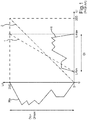
- FIG. 3 a diagram for illustrating a histogram spreading according to the method according to the invention
- FIG. 4 a diagram for illustrating the method, wherein a limit value other than in FIG. 3 is set
- FIG. 5 a diagram with an exemplary histogram for a raw image.
- FIG. 1 a histogram spreading is illustrated, as it is known from the prior art.
- An input histogram Hi is illustrated, that is a histogram, which can be formed of pixel values of pixels of a raw image of a camera sensor.
- each pixel can have a pixel value, which can be in a range from 0 to 255, that is an 8-bit pixel value.
- the pixel value can for example be a luminance value Li or hue value of the pixel.
- the smallest brightness value is denoted by Lmin.
- the greatest brightness value is denoted by Lmax.
- the dynamic range Di of the raw image is defined by the brightness values Lmin and Lmax.
- the input histogram Hi can be formed in the manner illustrated in FIG. 5 .
- FIG. 5 it is presented how for the input luminance values Li of the raw image, for each possible luminance value between 0 and 255, a number C (count) of those pixels is determined, which have the corresponding luminance value Li.
- the input histogram Hi results.
- FIG. 1 it is exemplified, how input luminance values Li can be mapped to output luminance values Lo by a spreading function 1 to generate from the raw image by pixel-wise transformation of the respective pixel value of each pixel of the raw image a pixel value for a corresponding pixel of the output image.
- a spreading function 1 to generate from the raw image by pixel-wise transformation of the respective pixel value of each pixel of the raw image a pixel value for a corresponding pixel of the output image.
- This output image has an output histogram Ho depending on the spreading function 1 .
- the spreading function 1 is selected such that the smallest brightness value Lmin of the raw image is mapped to the minimum luminance value 0.
- the greatest brightness value Lmax of the raw image is mapped to the maximally possible luminance value, here 255.
- the identity function 2 is also registered in the diagram.
- the output histogram Ho has luminance values having the full dynamic range Dmax.
- the maximum dynamic range Dmax includes the value 0 and the value 255.
- a motor vehicle 3 is illustrated, which can for example be a passenger car.
- the motor vehicle 3 can have a camera device 4 , which can include a camera sensor 5 and an image processing device 6 .
- a capturing range 7 of the camera sensor 5 can for example be oriented into an environment 8 of the motor vehicle 3 , for example into a front area of the motor vehicle 3 (as illustrated) or (not illustrated) into a rear area of the motor vehicle 3 or into a vehicle interior of the motor vehicle 3 .
- the image sensor 5 can be adapted to generate an image sequence of individual raw images R.
- the exposure period S sinutter speed
- an aperture A aperture
- an image sensor gain or gain G can be set, which then represent capturing parameters for the raw image R.
- a road 9 located in front of the motor vehicle 3 a house 10 and a tree 11 are imaged.
- the raw image R is relatively dark.
- a brightness in the environment 8 can be relatively low as it can for example occur in night drive or in a drive in a tunnel.
- an input histogram Hi for the raw image R results as it is also exemplarily illustrated in FIG. 2 .
- the luminance values Li do not reach the maximally possible luminance value, which can here be assumed as 255.
- a histogram spreading 12 can be provided by the image processing device 6 .
- the histogram spreading 12 can for example be realized by a program module of a processor of the image processing device 6 .
- the processor 6 can for example be a digital signal processing processor (DSP).
- DSP digital signal processing processor
- the histogram spreading can include a parameterizable spreading function 13 , which can have a limit value L (limit) as a parameter.
- L limit
- an output image I can be generated from the raw image R.
- the output image I can have an overall brightness, which is greater than the overall brightness of the raw image R.
- An output histogram Ho is exemplarily also illustrated in FIG. 2 for the output luminance values Lo of the output image I.
- the limit value L of the spreading function 13 constitutes a minimum value for the histogram values of the output histogram Ho.
- the output image I is transmitted to a further vehicle component 14 .
- the vehicle component 14 can for example be a display device such as for example a screen. A driver of the motor vehicle 3 can then view the output image I on the display device and hereby see the environment 8 .
- the vehicle component 14 can for example also be a driver assistance system, which can assist a driver in driving the motor vehicle 3 .
- the vehicle component 14 can then include an image recognition device, by which the road 8 and/or the house 10 and/or the tree 11 can be recognized, i.e. generally objects, in the output image I.
- FIG. 3 and FIG. 4 the operation of the histogram spreading 12 is explained for two capturing situations.
- an input histogram Hi of the raw image R and an output histogram Ho of the output image I after histogram spreading 12 are shown.
- the histogram spreading 12 is performed by means of the spreading function 13 , which can have the limit value Las a curve parameter.
- the limit value L is the minimum value for the output luminance values Lo of the pixels of the output image I.
- an ordinate setting or ordinate displacement 15 of a lower limit U of the spreading function 13 can be determined.
- an abscissa position 16 of the lower limit U and an abscissa position 17 of an upper limit O of the spreading function 13 can be set such that the lower limit U as the abscissa value corresponds to the minimum value Lmin of the input histogram Hi and the abscissa value 17 of the upper limit O corresponds to the maximum value Lmax of the input histogram Hi.
- the limit value L can be set depending on a brightness of the environment 8 or depending on a parameter value correlated with the brightness, for example the exposure period S and/or the gain G.
- the exposure period S or the gain G can for example be transmitted from the image sensor 5 to the image processing device 6 , as it is illustrated in FIG. 2 .
- values for the closure period S and/or the gain G have arisen, by which the limit value L has been set to a value L 1 by the image processing device 6 .
- an output histogram Ho results which extends from the lower limit L 1 to the maximum value, here 255, and hereby has a dynamic range Do, which is smaller than the maximum dynamic range Dmax.
- FIG. 4 a capturing situation is shown, in which a brightness value B 2 of the capturing situation is less than the brightness value B 1 of the capturing situation illustrated in FIG. 3 .
- the limit value was correspondingly switched from the value L 1 to the value L 2 , which is greater than the value L 1 , for example by a switching operation 18 .
- the dynamic range Do of the output histogram Ho decreases.
- limits are applied to the histogram stretching that adjust for the light levels of the environment that the imager sees.
- the light levels of the scene can be determined by monitoring the exposure and gain controls of the image, based on these readings we can adjust the histogram stretching limits of the image to give a brighter image at very low light and less bright and higher contrast at slightly higher light levels.
- Histogram stretching increases the contrast of the image. Histogram stretching can be either enabled or disabled on the system. Enabling applies a histogram stretching to the image across the max to min grayscale. Limits can be applied to the scale of the histogram.
- the image processing device applies limits on the histogram that can be dynamically updated based on the exposure gain of the imager (in other words based on the light level of the scene that the imager sees). By limiting the lower level of the histogram we can make the image brighter at very low light levels (reducing contrast). The side effect of this is as the light level increases the images at light level 10 lux.
- This invention will provide a limit at the lower level of the histogram at very low light (brightening the image) but dynamically updates the limit as the scene gets brighter, therefore keeping the contrast of the scene.
- the desired effect of the invention is to have limit L 2 at very low lightlevels (approx. 0.5 lux), and reading the exposure and gain controls of the imager dynamically update the histogram to limit 1 at a light level of 2 lux. Then once the exposure gain of the image is a value corresponding to a light level ⁇ 10 lux or above (when brightening the image is no longer required for example) switch to an unlimited histogram stretching image (increasing contrast to the max possible).
- histogram B (Limit L 1 ): At 2 lux, unlimited histogram stretching provides an image with a high contrast but still a little dark. We would like to apply histogram B with limit 1 that brightens the image slightly while a high contrast level is kept up.
- the invention can adjust the limit in response to the imager temperature to mitigate the influence of noise into the limit calculation.
Landscapes
- Engineering & Computer Science (AREA)
- Multimedia (AREA)
- Signal Processing (AREA)
- Physics & Mathematics (AREA)
- General Physics & Mathematics (AREA)
- Theoretical Computer Science (AREA)
- Studio Devices (AREA)
- Image Processing (AREA)
- Facsimile Image Signal Circuits (AREA)
- Mechanical Engineering (AREA)
Abstract
Description
- imager exposure=e
- imager gain=g
-
Limit 1 exposure/gain Threshold=E1 or G1 - Limit 2 exposure/gain Threshold=E2 or E2
- Unlimited=E3 or G3
- Histogram Stretching Limit=L
| If e > E1 or g > G1 | ||
| { | ||
| L = limit_1 | ||
| } | ||
| else if e > E2 or g > G2 | ||
| { | ||
| L = limit_2 | ||
| } | ||
| else if e > E3 or g > G3 | ||
| { | ||
| L = no limit = 0 | ||
| } | ||
Claims (12)
Applications Claiming Priority (4)
| Application Number | Priority Date | Filing Date | Title |
|---|---|---|---|
| DE102014114328 | 2014-10-02 | ||
| DE102014114328.0A DE102014114328A1 (en) | 2014-10-02 | 2014-10-02 | Motor vehicle camera device with histogram spread |
| DE102014114328.0 | 2014-10-02 | ||
| PCT/EP2015/072786 WO2016050954A1 (en) | 2014-10-02 | 2015-10-02 | Motor vehicle camera device with histogram spreading |
Publications (2)
| Publication Number | Publication Date |
|---|---|
| US20170243337A1 US20170243337A1 (en) | 2017-08-24 |
| US10769762B2 true US10769762B2 (en) | 2020-09-08 |
Family
ID=54288771
Family Applications (1)
| Application Number | Title | Priority Date | Filing Date |
|---|---|---|---|
| US15/515,801 Active 2036-03-05 US10769762B2 (en) | 2014-10-02 | 2015-10-02 | Motor vehicle camera device with histogram spreading |
Country Status (7)
| Country | Link |
|---|---|
| US (1) | US10769762B2 (en) |
| EP (1) | EP3202134A1 (en) |
| JP (1) | JP6411644B2 (en) |
| KR (1) | KR101822344B1 (en) |
| CN (1) | CN107079108B (en) |
| DE (1) | DE102014114328A1 (en) |
| WO (1) | WO2016050954A1 (en) |
Families Citing this family (3)
| Publication number | Priority date | Publication date | Assignee | Title |
|---|---|---|---|---|
| FR3068314B1 (en) * | 2017-06-30 | 2019-08-09 | Valeo Vision | LIGHT SYSTEM FOR MOTOR VEHICLE |
| FR3094299B1 (en) * | 2019-03-26 | 2022-04-01 | Valeo Systemes Dessuyage | PROTECTION ASSEMBLY FOR AN OPTICAL SENSOR OF A DRIVER ASSISTANCE SYSTEM FOR MOTOR VEHICLES |
| US11115602B2 (en) | 2019-06-11 | 2021-09-07 | Watchguard Video, Inc. | Emulating light sensitivity of a target |
Citations (7)
| Publication number | Priority date | Publication date | Assignee | Title |
|---|---|---|---|---|
| US20060274161A1 (en) * | 2005-06-03 | 2006-12-07 | Intel Corporation | Method and apparatus to determine ambient light using a camera |
| US20070146296A1 (en) * | 2005-12-28 | 2007-06-28 | Lg.Philips Lcd Co., Ltd. | Liquid crystal display device and fabricating and driving method thereof |
| JP2009058377A (en) | 2007-08-31 | 2009-03-19 | Hitachi Kokusai Electric Inc | Inspection apparatus |
| US20090251563A1 (en) * | 2007-12-26 | 2009-10-08 | Denso Corporation | Exposure control apparatus and exposure control program for vehicle-mounted electronic camera |
| US20130050516A1 (en) * | 2011-08-31 | 2013-02-28 | Daisuke HOJO | Imaging device, imaging method and hand-held terminal device |
| US20130076974A1 (en) * | 2011-09-26 | 2013-03-28 | Dolby Laboratories Licensing Corporation | Image Formats and Related Methods and Apparatuses |
| WO2014116715A1 (en) | 2013-01-25 | 2014-07-31 | Dolby Laboratories Licensing Corporation | Global display management based light modulation |
Family Cites Families (3)
| Publication number | Priority date | Publication date | Assignee | Title |
|---|---|---|---|---|
| US8285041B2 (en) * | 2004-09-14 | 2012-10-09 | Olympus Corporation | Image processing apparatus, image recording apparatus, and image processing method |
| JP4894907B2 (en) * | 2009-11-17 | 2012-03-14 | カシオ計算機株式会社 | Imaging apparatus, imaging processing method, and program |
| EP2552099B1 (en) * | 2011-07-27 | 2013-08-28 | Axis AB | Method and camera for providing an estimation of a mean signal to noise ratio value for an image |
-
2014
- 2014-10-02 DE DE102014114328.0A patent/DE102014114328A1/en active Pending
-
2015
- 2015-10-02 US US15/515,801 patent/US10769762B2/en active Active
- 2015-10-02 CN CN201580060876.8A patent/CN107079108B/en active Active
- 2015-10-02 WO PCT/EP2015/072786 patent/WO2016050954A1/en not_active Ceased
- 2015-10-02 EP EP15777911.7A patent/EP3202134A1/en not_active Withdrawn
- 2015-10-02 KR KR1020177008921A patent/KR101822344B1/en active Active
- 2015-10-02 JP JP2017517762A patent/JP6411644B2/en active Active
Patent Citations (7)
| Publication number | Priority date | Publication date | Assignee | Title |
|---|---|---|---|---|
| US20060274161A1 (en) * | 2005-06-03 | 2006-12-07 | Intel Corporation | Method and apparatus to determine ambient light using a camera |
| US20070146296A1 (en) * | 2005-12-28 | 2007-06-28 | Lg.Philips Lcd Co., Ltd. | Liquid crystal display device and fabricating and driving method thereof |
| JP2009058377A (en) | 2007-08-31 | 2009-03-19 | Hitachi Kokusai Electric Inc | Inspection apparatus |
| US20090251563A1 (en) * | 2007-12-26 | 2009-10-08 | Denso Corporation | Exposure control apparatus and exposure control program for vehicle-mounted electronic camera |
| US20130050516A1 (en) * | 2011-08-31 | 2013-02-28 | Daisuke HOJO | Imaging device, imaging method and hand-held terminal device |
| US20130076974A1 (en) * | 2011-09-26 | 2013-03-28 | Dolby Laboratories Licensing Corporation | Image Formats and Related Methods and Apparatuses |
| WO2014116715A1 (en) | 2013-01-25 | 2014-07-31 | Dolby Laboratories Licensing Corporation | Global display management based light modulation |
Non-Patent Citations (2)
| Title |
|---|
| International Search Report issued in corresponding application No. PCT/EP2015/072786 dated Jan. 20, 2016 (3 pages). |
| Written Opinion of the International Searching Authority issued in corresponding application No. PCT/EP2015/072786 dated Jan. 20, 2016 (5 pages). |
Also Published As
| Publication number | Publication date |
|---|---|
| US20170243337A1 (en) | 2017-08-24 |
| JP2017533505A (en) | 2017-11-09 |
| KR101822344B1 (en) | 2018-01-25 |
| KR20170047384A (en) | 2017-05-04 |
| EP3202134A1 (en) | 2017-08-09 |
| CN107079108A (en) | 2017-08-18 |
| CN107079108B (en) | 2021-03-09 |
| DE102014114328A1 (en) | 2016-04-07 |
| WO2016050954A1 (en) | 2016-04-07 |
| JP6411644B2 (en) | 2018-10-24 |
Similar Documents
| Publication | Publication Date | Title |
|---|---|---|
| EP2471691B1 (en) | Obstacle detection device, obstacle detection system provided therewith, and obstacle detection method | |
| US9604581B2 (en) | Vehicle vision system with color correction | |
| KR101629825B1 (en) | Display apparatus and method using high dynamic range for vehicle | |
| US20190092239A1 (en) | Image-pickup apparatus, image-pickup display method, and image-pickup display program | |
| CN106127693B (en) | Defogging system and defogging method | |
| US9214034B2 (en) | System, device and method for displaying a harmonized combined image | |
| US10531057B2 (en) | Vehicle-mounted display device | |
| US10769762B2 (en) | Motor vehicle camera device with histogram spreading | |
| US11758283B2 (en) | Image capture device and image adjusting method | |
| WO2011000392A1 (en) | Method and camera system for improving the contrast of a camera image | |
| US20170347008A1 (en) | Method for adapting a brightness of a high-contrast image and camera system | |
| EP2843937B1 (en) | Method for adapting a gamma curve of a camera system of a motor vehicle, camera system and motor vehicle | |
| JP2013162339A (en) | Imaging device | |
| US11790823B2 (en) | Image display device | |
| KR102333707B1 (en) | A low-light imaging system | |
| US10525902B2 (en) | Convertible roof opening detection for mirror camera | |
| CN109788211B (en) | Captured image display system, electronic mirror system, and captured image display method | |
| GB2527091A (en) | Anti-glare mirror | |
| JP7614893B2 (en) | Image processing device, image processing method, and program | |
| JP6407768B2 (en) | Imaging apparatus, image processing method, and program | |
| GB2617392A (en) | Apparatus and method for controlling a display | |
| CN119137626A (en) | Vehicle occupant monitoring system including an image acquisition device having a rolling shutter image sensor | |
| JP2016122878A (en) | Car camera |
Legal Events
| Date | Code | Title | Description |
|---|---|---|---|
| AS | Assignment |
Owner name: CONNAUGHT ELECTRONICS LTD., IRELAND Free format text: ASSIGNMENT OF ASSIGNORS INTEREST;ASSIGNOR:GRIFFIN, MARK PATRICK;REEL/FRAME:045285/0696 Effective date: 20180220 |
|
| STPP | Information on status: patent application and granting procedure in general |
Free format text: FINAL REJECTION MAILED |
|
| STPP | Information on status: patent application and granting procedure in general |
Free format text: RESPONSE AFTER FINAL ACTION FORWARDED TO EXAMINER |
|
| STPP | Information on status: patent application and granting procedure in general |
Free format text: ADVISORY ACTION MAILED |
|
| STPP | Information on status: patent application and granting procedure in general |
Free format text: DOCKETED NEW CASE - READY FOR EXAMINATION |
|
| STPP | Information on status: patent application and granting procedure in general |
Free format text: NON FINAL ACTION MAILED |
|
| STPP | Information on status: patent application and granting procedure in general |
Free format text: RESPONSE TO NON-FINAL OFFICE ACTION ENTERED AND FORWARDED TO EXAMINER |
|
| STPP | Information on status: patent application and granting procedure in general |
Free format text: NOTICE OF ALLOWANCE MAILED -- APPLICATION RECEIVED IN OFFICE OF PUBLICATIONS |
|
| STPP | Information on status: patent application and granting procedure in general |
Free format text: AWAITING TC RESP., ISSUE FEE NOT PAID |
|
| STCF | Information on status: patent grant |
Free format text: PATENTED CASE |
|
| MAFP | Maintenance fee payment |
Free format text: PAYMENT OF MAINTENANCE FEE, 4TH YEAR, LARGE ENTITY (ORIGINAL EVENT CODE: M1551); ENTITY STATUS OF PATENT OWNER: LARGE ENTITY Year of fee payment: 4 |