US10767799B2 - Vapor coupler - Google Patents
Vapor coupler Download PDFInfo
- Publication number
- US10767799B2 US10767799B2 US15/866,918 US201815866918A US10767799B2 US 10767799 B2 US10767799 B2 US 10767799B2 US 201815866918 A US201815866918 A US 201815866918A US 10767799 B2 US10767799 B2 US 10767799B2
- Authority
- US
- United States
- Prior art keywords
- coupler
- handle
- adaptor
- seal assembly
- coupler body
- Prior art date
- Legal status (The legal status is an assumption and is not a legal conclusion. Google has not performed a legal analysis and makes no representation as to the accuracy of the status listed.)
- Active, expires
Links
Images


Classifications
-
- F—MECHANICAL ENGINEERING; LIGHTING; HEATING; WEAPONS; BLASTING
- F16—ENGINEERING ELEMENTS AND UNITS; GENERAL MEASURES FOR PRODUCING AND MAINTAINING EFFECTIVE FUNCTIONING OF MACHINES OR INSTALLATIONS; THERMAL INSULATION IN GENERAL
- F16L—PIPES; JOINTS OR FITTINGS FOR PIPES; SUPPORTS FOR PIPES, CABLES OR PROTECTIVE TUBING; MEANS FOR THERMAL INSULATION IN GENERAL
- F16L37/00—Couplings of the quick-acting type
- F16L37/08—Couplings of the quick-acting type in which the connection between abutting or axially overlapping ends is maintained by locking members
- F16L37/12—Couplings of the quick-acting type in which the connection between abutting or axially overlapping ends is maintained by locking members using hooks, pawls, or other movable or insertable locking members
- F16L37/18—Joints tightened by eccentrics or rotatable cams
-
- F—MECHANICAL ENGINEERING; LIGHTING; HEATING; WEAPONS; BLASTING
- F16—ENGINEERING ELEMENTS AND UNITS; GENERAL MEASURES FOR PRODUCING AND MAINTAINING EFFECTIVE FUNCTIONING OF MACHINES OR INSTALLATIONS; THERMAL INSULATION IN GENERAL
- F16L—PIPES; JOINTS OR FITTINGS FOR PIPES; SUPPORTS FOR PIPES, CABLES OR PROTECTIVE TUBING; MEANS FOR THERMAL INSULATION IN GENERAL
- F16L37/00—Couplings of the quick-acting type
- F16L37/02—Couplings of the quick-acting type in which the connection is maintained only by friction of the parts being joined
- F16L37/04—Couplings of the quick-acting type in which the connection is maintained only by friction of the parts being joined with an elastic outer part pressing against an inner part by reason of its elasticity
- F16L37/05—Couplings of the quick-acting type in which the connection is maintained only by friction of the parts being joined with an elastic outer part pressing against an inner part by reason of its elasticity tightened by the pressure of a mechanical organ
-
- F—MECHANICAL ENGINEERING; LIGHTING; HEATING; WEAPONS; BLASTING
- F16—ENGINEERING ELEMENTS AND UNITS; GENERAL MEASURES FOR PRODUCING AND MAINTAINING EFFECTIVE FUNCTIONING OF MACHINES OR INSTALLATIONS; THERMAL INSULATION IN GENERAL
- F16L—PIPES; JOINTS OR FITTINGS FOR PIPES; SUPPORTS FOR PIPES, CABLES OR PROTECTIVE TUBING; MEANS FOR THERMAL INSULATION IN GENERAL
- F16L37/00—Couplings of the quick-acting type
- F16L37/28—Couplings of the quick-acting type with fluid cut-off means
- F16L37/38—Couplings of the quick-acting type with fluid cut-off means with fluid cut-off means in only one of two pipe-end fittings
- F16L37/44—Couplings of the quick-acting type with fluid cut-off means with fluid cut-off means in only one of two pipe-end fittings with one lift valve being actuated to initiate the flow through the coupling after the two coupling parts are locked against withdrawal
-
- B—PERFORMING OPERATIONS; TRANSPORTING
- B01—PHYSICAL OR CHEMICAL PROCESSES OR APPARATUS IN GENERAL
- B01L—CHEMICAL OR PHYSICAL LABORATORY APPARATUS FOR GENERAL USE
- B01L3/00—Containers or dishes for laboratory use, e.g. laboratory glassware; Droppers
- B01L3/56—Labware specially adapted for transferring fluids
- B01L3/563—Joints or fittings; Separable fluid transfer means to transfer fluids between at least two containers, e.g. connectors
Definitions
- Exemplary embodiments of the present disclosure relate to fluid system components. More particularly, exemplary embodiments of the present disclosure relate to vapor coupler devices for use in fluid systems.
- a common source of fluid or vapor leaks are the connections between various components of the fluid systems.
- a fuel transport vehicle is delivering liquid through a conduit such as a hose into a fuel tank
- the hose is attached to the vehicle at one end and to a fuel tank at the other end.
- the hose may be attached to the fuel tank via a coupler and an adaptor, each of which includes a valve.
- a coupler and an adaptor are connected and disconnected properly, and their associated valves function properly, current couplers, adaptors, and their associated valves often still allow for fluids or vapors to leak, spill, or otherwise be exposed to the environment.
- a fluid system coupler includes a coupler body at least partially defining a fluid passageway therethrough.
- the coupler body has an open end configured to selectively receive an adaptor therein.
- a seal assembly is movably disposed within the coupler body.
- One or more lever cams are pivotally connected to the coupler body.
- a handle is movably connected to the coupler body and is operatively associated with the seal assembly and the one or more lever cams such that movement of the handle moves the seal assembly and enables the one or more lever cams pivot relative to the coupler body.
- a fluid system coupler in another embodiment, includes a coupler body having an open end for receiving an adaptor therein.
- a seal assembly is movably disposed within the coupler body for selective sealing engagement with the adaptor.
- Lever cams pivot into or out of slots in the coupler body between locked and unlocked positions to fasten or unfasten the adaptor to the coupler.
- a handle is movably connected to the coupler body. Movement of the handle moves the seal assembly within the coupler body into or out of engagement with the adaptor. Movement of the handle also results in movement of the lever cams between the locked and unlocked positions.
- a poppet assembly is mounted to the seal assembly. The poppet assembly can selectively open or close a fluid passageway through the coupler.
- a fluid system coupler in one embodiment, includes a coupler body at least partially defining a fluid passageway therethrough.
- the coupler body has an open end configured to selectively receive an adaptor therein.
- One or more slots extend through the coupler body adjacent to the open end.
- a seal assembly is disposed within the coupler body and is movable between a first position and a second position to engage or disengage the adaptor.
- the seal assembly has one or more central openings to allow fluid or vapor to flow through the seal assembly.
- the seal assembly includes one or more seals that interface with an inner surface of the coupler body to prevent the flow of fluid or vapor between the seal assembly and the coupler body.
- the seal assembly also has one or more wings that extend through the one or more slots in the coupler body. Further, the seal assembly includes a guide.
- One or more lever cams are pivotally connected to the coupler body.
- the one or more lever cams are movable between a locked position and an unlocked position.
- a portion of the one or more lever cams extends through the one or more slots in the coupler body to engage the adaptor when the one or more lever cams are in the locked position.
- the one or more lever cams are at least partially withdrawn from the one or more slots to disengage the adaptor when the one or more lever cams are in the unlocked position.
- a handle is movable connected to the coupler body.
- the handle is movable between a first position and a second position. Movement of the handle from the first position to the second position moves the seal assembly from the first position to the second position to disengage the adaptor and enables the one or more lever cams to move to the unlocked position to disengage the adaptor. In contrast, movement of the handle from the second position to the first position moves the seal assembly from the second position to the first position and moves the one or more lever cams to locked position.
- a poppet assembly is movably mounted to the guide of the seal assembly.
- the poppet assembly comprises a shaft slidably disposed at least partially within the guide and a seal plate connected to the shaft.
- the poppet assembly is movable between an open configuration and a closed configuration.
- the seal plate closes off the one or more central openings in the seal assembly when the poppet assembly is in the closed configuration.
- the seal plate is spaced apart from the seal assembly to enable fluid or vapor to flow through the one or more central openings when the poppet assembly is in the open configuration.
- a fluid system coupler in still another embodiment, includes a coupler body at least partially defining a fluid passageway therethrough and having an open end configured to selectively receive an adaptor therein.
- a seal assembly is movably disposed within the coupler body.
- a poppet assembly is movably mounted to the seal assembly and includes a seal plate that is movable between an open configuration and a closed configuration.
- a handle is movably connected to the coupler body and is operatively associated with the seal assembly such that movement of the handle moves the seal assembly relative to the coupler body.
- FIG. 1 is a perspective view of the coupling device according to one embodiment of the present disclosure showing the adaptor and coupler separated from one another.
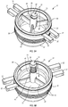
- FIG. 2 is an end perspective view of the coupler of the coupling device of FIG. 1 .
- FIGS. 3A and 3B are top views of the coupler of FIG. 2 .
- FIGS. 4A and 4B are side views of the coupler of FIG. 2 .
- FIG. 5A-5D are perspective view of a seal assembly and poppet assembly of the coupler of FIG. 2-4B .
- FIGS. 6A and 6B are perspective views of a portion of the coupler of FIGS. 2-4B .
- FIGS. 7A and 7B are cross-sectional views of the coupling device of FIG. 1 .
- FIG. 8 is a partial cross-section view of an adaptor seal of the sealing assembly of FIGS. 5A-5D .
- Coupling 10 includes a coupler 12 and an adaptor 14 that are selectively securable together about a common axis by fastening features provided on such members.
- the coupler 12 and adaptor 14 can be readily fastened together irrespective of their angular positions about such axis.
- the coupler 12 includes a seal assembly for sealing the connection with the adaptor 14 .
- the coupler 12 includes a poppet assembly for preventing the flow of fluid or vapor through the coupler 12 when the coupler 12 is disconnected from the adaptor 14 .
- the adaptor 14 can also include a seal assembly and/or a poppet assembly to help seal the connection with the coupler 12 and/or for preventing the flow of fluid or vapor therethrough when the adaptor 14 is disconnected from the coupler 12 .
- the poppet assemblies can thus provide a dry-break, such that a very limited amount of fluid or vapor, if any, escapes or is lost from the coupling device 10 when the coupler 12 and adaptor 14 are taken apart.
- the coupler 12 is a female member and the adaptor 14 is a male member.
- the coupler 12 includes an open end or bore configured to receive a terminal end portion of the adaptor 14 therein.
- Fastening features are provided on the coupler 12 and adaptor 14 for fastening and unfastening the coupler 12 and adaptor 14 .
- the fastening features include an annular grove 16 and one or more lever cams 18 . More specifically, the annular groove 16 is formed in an outer surface of the adaptor 14 near the terminal end that is received into the coupler 12 .
- the lever cams 18 can pivot so that portions of the lever cams 18 are positioned within the groove 16 to fasten the coupler 12 and the adaptor 14 together.
- the lever cams 18 can also pivot away from the adaptor 14 so that the lever cams 18 are removed from the groove 16 to unfasten the coupler 12 and the adaptor 14 from one another.
- the coupler 12 includes a seal assembly 20 and a poppet assembly 22 .
- the seal assembly 20 cooperates with the terminal end of the adaptor 14 to create a seal between the coupler 12 and the adaptor 14 to limit or prevent fluid and vapors from escaping the coupling 10 .
- the poppet assembly 22 is configured to seal off the flow of fluid or vapors through the coupler 12 when the coupler 12 is disconnected from the adaptor 14 .
- the coupler 12 also includes various handles 24 , 26 , 28 , which can be used to move or manipulate coupler 12 . Additionally, some of the handles can be used to actuate other components of the coupler 12 .
- the handle 28 can pivot or otherwise move. Pivoting or movement of the handle 28 can facilitate the movement of the lever cams 18 into or out of engagement with the groove 16 in the adaptor 14 . The pivoting or movement of the handle 28 can also move the seal assembly 20 and/or the poppet assembly 22 .
- movement of the seal assembly 20 can create or break a seal formed between the coupler 12 and the adaptor 14 and movement of the poppet assembly 22 (or portions thereof) can open or close a flow path for fluid or vapors through the coupler 12 and/or coupling 10 .
- FIGS. 3A-3B illustrate top views of coupler 12 and the FIGS. 4A-4B illustrate side views thereof.
- handle 28 is pivotally or movably mounted in one or more channels, recesses, or holes 30 to enable handle 28 to move or pivot between a first position as shown in FIGS. 3A and 4A and a second position shown in FIGS. 3B and 4B .
- handle 28 when handle 28 is in the first position, handle 28 is positioned further away from handle 26 and closer to the open end of coupler 12 that receives adaptor 14 than when handle 28 is in the second position.
- handle 28 is positioned closer to handle 26 and further away from the open end of coupler 12 than when handle 28 is in the first position.
- Handle 28 is linked to seal assembly 20 such that movement of handle 28 between the first and second positions causes the seal assembly 20 to also move between first and second positions. More specifically, as can be seen in the Figures, seal assembly 20 includes wings 32 that extend through slots 34 in the body of coupler 12 . Connected between wings 32 and handle 28 are sliders 36 . In the illustrated embodiment, sliders 36 are mounted to wings 32 via a pin 35 . In some embodiments, sliders 36 can rotate about pins 35 . Sliders 36 also include an aperture 37 through which handle 28 extends. In some embodiments, sliders 36 can rotate about handle 28 . Additionally, in some embodiments, handle 28 can slide through apertures 37 as handle 28 moves between the first and second positions.
- connection between handle 28 and wings 32 by sliders 36 links the movement of handle 28 and seal assembly 20 .
- movement of handle 28 between the first position and the second position results in the movement of seal assembly 20 between the first position and the second position (as can be seen by the different positions of wings 32 ).
- sliders 36 In addition to linking together handle 28 and seal assembly 20 , sliders 36 also interact with the lever cams 18 . More specifically, sliders 36 are disposed against outer surfaces of lever cams 18 . When handle 28 is moved to the first position shown in FIGS. 3A and 4A , sliders 36 press against lever cams 18 to move lever cams 18 to a closed or locked position. In the closed or locked position, at least a portion of lever cams 18 extend through slots 34 so as to be positionable within groove 16 of adaptor 14 to secure coupler 12 and adaptor 14 together. When handle 28 is moved to the second position shown in FIGS. 3B and 4B , sliders 36 allow lever cams 18 to move to an open or unlocked position. In the open or unlocked position, lever cams 18 are at least partially withdrawn from slots 34 so as to be removed from groove 16 , thereby disconnecting coupler 12 from adaptor 14 .
- FIGS. 5A-5D illustrate seal assembly 20 and poppet assembly 22 apart from the rest of coupler 12 . More specifically, FIGS. 5A-5D illustrate top and bottom perspective views with poppet assembly 22 in an open configuration ( FIGS. 5A and 5C ) and a closed configuration ( FIGS. 5B and 5D ).
- FIGS. 5A-5D illustrate top and bottom perspective views with poppet assembly 22 in an open configuration ( FIGS. 5A and 5C ) and a closed configuration ( FIGS. 5B and 5D ).
- poppet assembly 22 When poppet assembly 22 is in the open configuration, fluid and/or vapors can flow though coupler 12 .
- poppet assembly 22 is in the closed configuration, fluid and/or vapors are prevented from flowing through or out of coupler 12 .
- seal assembly 20 includes a collar 38 having an outer surface that generally corresponds in size and shape to an inner surface of the bore or open end of coupler 12 .
- Wings 32 extend outward from the outer surface of collar 38 .
- the outer surface of collar 38 also includes annular grooves 40 in which seals 42 are disposed. Seals 42 can interact with the inner surface of the coupler body to limit or prevent fluid and/or vapors from passing between the coupler body and collar 38 .
- Collar 38 also includes an annular groove 40 in a lower surface thereof with a seal 42 disposed therein, as shown in FIG. 5C .
- the seal 42 in the lower surface of collar 38 interacts with poppet assembly 22 to seal off the flow of fluid or vapors through coupler 12 .
- Collar 38 also has a central opening 44 therethrough through which fluid and/or vapors can pass when the poppet assembly 22 is in an open configuration.
- Mounted within the central opening 44 is a guide 46 .
- the guide 46 is connected to collar 38 by supports 48 .
- Guide 46 includes a central bore in which poppet assembly 22 is mounted.
- Poppet assembly 22 includes a shaft 50 with a seal plate 52 mounted thereon. Shaft 50 is slidably disposed within guide 46 to enable poppet assembly 22 to move between the open and closed configurations.
- seal plate 52 blocks or closes off the central opening 44 . Seal plate 52 can interact with the seal 42 in the lower surface of collar 38 to prevent fluid or vapors from passing therebetween.
- seal plate 52 is spaced apart from collar 38 , thereby allowing fluid and vapors to flow around seal plate 52 and through central opening 44 in collar 38 .
- poppet assembly 22 is biased to the closed configuration.
- the illustrated embodiment includes a biasing member 54 (e.g., coil spring) disposed around shaft 50 to urge poppet assembly 22 towards the closed configuration.
- biasing member 54 is disposed between a head 56 of shaft 50 and a shoulder on or within guide 46 .
- Biasing member 54 urges head 56 away from the shoulder on or within guide 46 , which urges seal plate 52 towards the lower surface of collar 38 .
- an element of adaptor 14 may interact with head 56 to overcome the biasing force of biasing member 54 and move poppet assembly 22 towards the open configuration.
- FIGS. 6A and 6B show close up views of the interaction between handle 28 , lever cams 18 , and seal assembly 20 .
- handle 28 is in the first position, seal assembly 20 is also in the first position (e.g., closer to the open end of coupler 12 ), and lever cams 18 are pushed to the closed or locked position.
- FIG. 6B handle 28 is in the second position, seal assembly 20 is also in the second position (e.g., further from the open end of coupler 12 ), and lever cams 18 are pivoted or moved to the open or unlocked position.
- seal assembly 20 is biased towards the first position by biasing members 58 (e.g., coil springs).
- biasing members 58 are disposed between wings 32 and shoulders 60 formed on the coupler body. Biasing members 58 apply a biasing force to wings 32 (and thus seal assembly 20 ) in the direction of the first position. Due to the connection between seal assembly 20 and handle 28 via sliders 36 , the biasing force from biasing members 58 is transferred to handle 28 , thereby biasing and moving handle 28 to the first position.
- lever cams 18 are pivotally mounted to the coupler body by way of pivot pins 62 . As such, lever cams 18 can pivot between the closed or locked position shown in FIG. 6A and the open or unlocked position shown in FIG. 6B .
- a biasing member 64 e.g., spring
- slider 36 forces lever cam 18 to move to the closed or locked position. More specifically, when seal assembly 20 and handle 28 move to the first position, slider 36 engages a shoulder 66 (see FIGS. 6B-7B ) on lever cam 18 in a manner that urges lever cam 18 towards the closed or locked position.
- biasing force of biasing members 58 may be larger than the biasing force of biasing members 64 .
- the biasing force of biasing members 58 may urge seal assembly 20 towards the first position with sufficient force to overcome the biasing force of biasing members 64 .
- lever cams 18 are biased towards the closed or locked position.
- coupler 12 may include one or more stops to limit the range of movement of various components thereof.
- one or more stops may be provided on the coupler body or on the lever cams 18 to limit the movement of seal assembly 20 and/or handle 28 .
- each of lever cams 18 includes a stop 68 that limits the movement of seal assembly 20 and handle 28 towards the open end of coupler 12 .
- stop 68 limits the movement of seal assembly 20 and handle 28 towards the open end of coupler 12 .
- channels, recesses, or holes 30 may also include one or more stops to limit the pivoting or other movement of handle 28 .
- the stops 68 of the lever cams 18 can also provide a visional indication as to whether the lever cams 18 are in the closed or locked position or in the open or unlocked position.
- a surface 69 on one or both of the lever cams 18 can include a visual indicator (e.g., color, letters, words, symbol).
- the slider 36 may include a tab 71 that may selectively cover or reveal the surface 69 .
- the tab 71 covers the surface 69 when the lever cams 18 are in the closed or locked position.
- FIG. 6A the tab 71 covers the surface 69 when the lever cams 18 are in the closed or locked position.
- the tab 71 is withdrawn from over the surface 69 when the lever cams 18 are in the open or unlocked position such that an operator can see surface 71 .
- Being able to see the visual indicator on surface 69 e.g., when tab 71 is withdrawn from over surface 69
- the visual indicator on surface 69 can indicate to an operator that the lever cams 18 are in the open or unlocked position.
- not being able to see the visual indicator on surface 69 e.g., when tab 71 is withdrawn from over surface 69
- FIGS. 7A and 7B illustrate cross-section views of coupling 10 in an uncoupled configuration and a coupled configuration, respectively.
- handle 28 has been moved to the second position.
- biasing members 58 have been compressed and sliders 36 and sealing assembly 20 have been moved away from the open end of coupler 12 in connection with the movement of handle 28 .
- sliders 36 are disengaged from shoulders 66 on lever cams 18 when handle 28 is moved to the second position. Because sliders 36 are disengaged from shoulders 66 , biasing members 64 can urge lever cams 18 outward as shown. With lever cams 18 pivoted outward as shown, coupler 12 is in a configuration to receive the end of adaptor 14 therein.
- poppet assembly 22 is in a closed configuration.
- biasing member 54 is urging shaft 50 and connected seal plate 52 to the closed configuration in which seal plate 52 is positioned against collar 38 to close or seal off the central opening 44 through collar 38 .
- FIG. 7B the end of adaptor 14 has been inserted into the open end of coupler 12 and handle 28 has been released so that it has moved to the first position.
- biasing members 58 urge seal assembly 20 and handle 28 to the first position.
- an adaptor seal 70 mounted on collar 38 engages the terminal end of adaptor 14 to create a fluid and vapor tight seal between coupler 12 and adaptor 14 .
- the biasing force from biasing members 58 also urges sliders 36 into engagement with shoulders 66 on lever cams 18 . As shown in FIG. 7B , such engagement forces lever cams 18 to pivot inward towards adaptor 14 .
- the biasing force from biasing members 58 can be sufficiently large to overcome the biasing force of biasing members 64 , thereby causing lever cams 18 to pivot inward.
- lever cams 18 are pivoted inward, a portion of lever cams 18 extends into groove 16 , which locks adaptor 14 to coupler 12 and prevents adaptor 14 from being removed until handle 28 is moved to the second position.
- adaptor 14 includes an engagement feature 72 that can engage poppet assembly 22 .
- engagement feature 72 is positioned within adaptor 14 such that insertion of adaptor 14 into coupler 12 causes engagement feature 72 to engage head 56 of poppet assembly 22 .
- engagement feature 72 applies a force on head 56 sufficient to overcome the biasing force of biasing member 54 .
- shaft 50 moves through guide 46 in a direction away from the open end of coupler 12 . Such movement causes seal plate 52 to disengage collar 38 to allow for fluid or vapor to pass therebetween and through collar 38 and coupling 10 .
- handle 28 is moved from the first position to the second position. Such movement causes sliders 36 to disengage shoulders 66 , thereby allowing lever cams 18 to pivot outward under the influence of biasing members 64 . The outward movement of lever cams 18 withdraws lever cams 18 from groove 16 , thereby allowing adaptor 14 to be withdrawn from coupler 12 .
- seal assembly 20 moves to the second position.
- Such movement causes collar 38 to move towards seal plate 52 and away from adaptor 14 .
- Such movement breaks the seal formed between coupled 12 and adaptor 14 by adaptor seal 70 and also creates a seal between collar 38 and the seal plate 52 .
- the biasing force of biasing member 54 urges seal plate 52 towards collar 38 and the seal 40 thereof.
- FIG. 8 illustrates a partial cross-sectional view of adaptor seal 70 .
- Adaptor seal 70 is generally in the form of a circular ring.
- adaptor seal 70 includes a first portion 72 that has a substantially circular cross-section shape.
- First portion 72 can be received within an annular groove in collar 38 .
- Adaptor seal 70 also includes a second portion 74 that has a substantially rectangular cross-sectional shape that is oriented substantially tangential to first portion 72 .
- second portion 74 is oriented so that a major surface thereof is generally parallel to an end surface of adaptor 14 that will engage adaptor seal 70 .
- the length of second portion 74 (in the radial direction) is larger than the diameter of first portion.
- Adaptor seal 70 also includes a third portion 76 extending from second portion 74 .
- third portion 76 has a generally rectangular cross-sectional shape.
- Third portion 76 extends from an end of section portion 74 at an angle and generally towards the center of adaptor seal 70 (e.g., radially inward) and towards adaptor 14 (e.g., away from first portion 72 ).
- second and third portions 74 , 76 form an acute angle and the length of third portion 76 is shorter than the length of second portion 74 .
- third portion 76 may be longer or the same length as second portion 74 .
- third portion 76 may extend from an opposite end of second portion and may extend generally away from the center of adaptor seal 70 (e.g., radially outward) and towards adaptor 14 (e.g., away from first portion 72 ).
- adaptor seal 70 When adaptor 14 is connected to coupler 12 , the end of adaptor 14 engages adaptor seal 70 . In some embodiments, the end of adaptor 14 engages third portion 76 and compresses third portion 76 between second portion 74 and the end of adaptor 14 . In other embodiments, third portion 76 extends around the outer (or inner) surface of adaptor 14 and the end of adaptor 14 engages second portion 74 . In any event, adaptor seal 70 can create a fluid and/or vapor tight seal between coupler 12 and adaptor 14 .
Landscapes
- Engineering & Computer Science (AREA)
- General Engineering & Computer Science (AREA)
- Mechanical Engineering (AREA)
- Quick-Acting Or Multi-Walled Pipe Joints (AREA)
Abstract
Description
Claims (23)
Priority Applications (2)
| Application Number | Priority Date | Filing Date | Title |
|---|---|---|---|
| US15/866,918 US10767799B2 (en) | 2017-01-17 | 2018-01-10 | Vapor coupler |
| CA2992225A CA2992225A1 (en) | 2017-01-17 | 2018-01-17 | Vapor coupler |
Applications Claiming Priority (2)
| Application Number | Priority Date | Filing Date | Title |
|---|---|---|---|
| US201762447423P | 2017-01-17 | 2017-01-17 | |
| US15/866,918 US10767799B2 (en) | 2017-01-17 | 2018-01-10 | Vapor coupler |
Publications (2)
| Publication Number | Publication Date |
|---|---|
| US20180202593A1 US20180202593A1 (en) | 2018-07-19 |
| US10767799B2 true US10767799B2 (en) | 2020-09-08 |
Family
ID=62841067
Family Applications (1)
| Application Number | Title | Priority Date | Filing Date |
|---|---|---|---|
| US15/866,918 Active 2038-12-29 US10767799B2 (en) | 2017-01-17 | 2018-01-10 | Vapor coupler |
Country Status (2)
| Country | Link |
|---|---|
| US (1) | US10767799B2 (en) |
| CA (1) | CA2992225A1 (en) |
Cited By (3)
| Publication number | Priority date | Publication date | Assignee | Title |
|---|---|---|---|---|
| US20210078509A1 (en) * | 2018-05-01 | 2021-03-18 | Thetford Bv | Discharge device for vehicle wastewater management system |
| US20250153996A1 (en) * | 2023-11-13 | 2025-05-15 | Knappco Llc | Vapor line coupler |
| US12617667B2 (en) * | 2024-11-12 | 2026-05-05 | Knappco Llc | Vapor line coupler |
Families Citing this family (6)
| Publication number | Priority date | Publication date | Assignee | Title |
|---|---|---|---|---|
| US11196206B2 (en) * | 2018-07-19 | 2021-12-07 | Hirel Connectors, Inc. | Electrical connector with field serviceable shell assembly |
| CN109743947A (en) * | 2019-03-13 | 2019-05-14 | 安徽万户农业科技有限公司 | A kind of pole type spray appliance |
| SE543523C2 (en) | 2019-06-27 | 2021-03-16 | Mann Teknik Ab | A coupler comprising a handle and a handle therefor |
| GB2592649A (en) * | 2020-03-05 | 2021-09-08 | Trelleborg Westbury Ltd | Fluid conduit interlock |
| IT202300002577A1 (en) * | 2023-02-15 | 2024-08-15 | Acs Dobfar Spa | DEVICE FOR CONNECTING PIPES IN ASEPTIC ENVIRONMENT |
| CN117658051B (en) * | 2023-12-20 | 2026-01-30 | 阳新弘盛铜业有限公司 | A device for preventing the sulfuric acid loading arm from falling off the acid transport pipe. |
Citations (11)
| Publication number | Priority date | Publication date | Assignee | Title |
|---|---|---|---|---|
| US2896971A (en) * | 1954-08-31 | 1959-07-28 | Joseph F Kolar | Valve actuator for fluid connector |
| US4030524A (en) * | 1975-05-19 | 1977-06-21 | Dover Corporation | Coupler |
| US4135551A (en) * | 1977-05-31 | 1979-01-23 | Fmc Corporation | Modified dry-break coupler |
| US4234161A (en) * | 1978-12-06 | 1980-11-18 | Dover Corporation | Linkage assembly for a coupler |
| US5535984A (en) * | 1994-06-07 | 1996-07-16 | Dover Corporation | Safety coupler locking means |
| US6009901A (en) * | 1998-01-16 | 2000-01-04 | Emco Wheaton Dtm, Inc. | Dry disconnect coupling |
| US20150377397A1 (en) * | 2013-02-12 | 2015-12-31 | Boccard | Manual connection for connecting two fluid ducts |
| US20160312939A1 (en) * | 2015-04-27 | 2016-10-27 | Engineered Controls International, Llc | Rapid-connect coupler with vent stop |
| US20170334640A1 (en) * | 2016-05-20 | 2017-11-23 | Opw-Engineered Systems, Inc. | Coupler with quick release handle and valve assemblies |
| US20190077652A1 (en) * | 2016-03-11 | 2019-03-14 | Fort Vale Engineering Limited | Valve for vapour recovery system |
| US10386017B2 (en) * | 2015-12-03 | 2019-08-20 | Engineered Controls International, Llc | Low emission nozzles and receptacles |
-
2018
- 2018-01-10 US US15/866,918 patent/US10767799B2/en active Active
- 2018-01-17 CA CA2992225A patent/CA2992225A1/en not_active Abandoned
Patent Citations (11)
| Publication number | Priority date | Publication date | Assignee | Title |
|---|---|---|---|---|
| US2896971A (en) * | 1954-08-31 | 1959-07-28 | Joseph F Kolar | Valve actuator for fluid connector |
| US4030524A (en) * | 1975-05-19 | 1977-06-21 | Dover Corporation | Coupler |
| US4135551A (en) * | 1977-05-31 | 1979-01-23 | Fmc Corporation | Modified dry-break coupler |
| US4234161A (en) * | 1978-12-06 | 1980-11-18 | Dover Corporation | Linkage assembly for a coupler |
| US5535984A (en) * | 1994-06-07 | 1996-07-16 | Dover Corporation | Safety coupler locking means |
| US6009901A (en) * | 1998-01-16 | 2000-01-04 | Emco Wheaton Dtm, Inc. | Dry disconnect coupling |
| US20150377397A1 (en) * | 2013-02-12 | 2015-12-31 | Boccard | Manual connection for connecting two fluid ducts |
| US20160312939A1 (en) * | 2015-04-27 | 2016-10-27 | Engineered Controls International, Llc | Rapid-connect coupler with vent stop |
| US10386017B2 (en) * | 2015-12-03 | 2019-08-20 | Engineered Controls International, Llc | Low emission nozzles and receptacles |
| US20190077652A1 (en) * | 2016-03-11 | 2019-03-14 | Fort Vale Engineering Limited | Valve for vapour recovery system |
| US20170334640A1 (en) * | 2016-05-20 | 2017-11-23 | Opw-Engineered Systems, Inc. | Coupler with quick release handle and valve assemblies |
Cited By (4)
| Publication number | Priority date | Publication date | Assignee | Title |
|---|---|---|---|---|
| US20210078509A1 (en) * | 2018-05-01 | 2021-03-18 | Thetford Bv | Discharge device for vehicle wastewater management system |
| US11912213B2 (en) * | 2018-05-01 | 2024-02-27 | Thetford Bv | Discharge device for vehicle wastewater management system |
| US20250153996A1 (en) * | 2023-11-13 | 2025-05-15 | Knappco Llc | Vapor line coupler |
| US12617667B2 (en) * | 2024-11-12 | 2026-05-05 | Knappco Llc | Vapor line coupler |
Also Published As
| Publication number | Publication date |
|---|---|
| CA2992225A1 (en) | 2018-07-17 |
| US20180202593A1 (en) | 2018-07-19 |
Similar Documents
| Publication | Publication Date | Title |
|---|---|---|
| US10767799B2 (en) | Vapor coupler | |
| US9909703B2 (en) | Fluid coupling and method | |
| US4271865A (en) | Dry break coupling valve | |
| US8360103B2 (en) | Split valve | |
| US5884648A (en) | Coupling valve apparatus and method | |
| US20150167882A1 (en) | Coupling for connecting fluid-conducting lines | |
| US9562639B1 (en) | Method for cam lock fitting | |
| US6412827B1 (en) | Lockable quick connect/disconnect coupling | |
| US7147004B1 (en) | Check valve for cam lock fitting | |
| US5413309A (en) | Push-to-connect coupler with interlocking three-way valve | |
| US9732894B1 (en) | Double cam levers and safety lock for cam lock fitting | |
| US9851017B2 (en) | Locking mechanism for unisex ball valve coupling | |
| US10550983B2 (en) | Double cam levers and safety lock for cam lock fitting | |
| US10330206B2 (en) | Movable shutter for a fluid conduit | |
| US10962161B2 (en) | Rotating female portion and safety lock for cam lock fitting | |
| US10563773B2 (en) | Fluid system coupling with internal valves | |
| US2905486A (en) | Coupling device | |
| US10703388B2 (en) | Refueling adapter | |
| CA2931359C (en) | Combination spill prevention valve actuator device | |
| US11293574B2 (en) | Coupling | |
| US20190011070A1 (en) | Divisible valve connector | |
| US8042571B2 (en) | Rigid mount anti-leak fluid coupler | |
| EP2103860A2 (en) | Rigid mount anti-leak fluid coupler |
Legal Events
| Date | Code | Title | Description |
|---|---|---|---|
| FEPP | Fee payment procedure |
Free format text: ENTITY STATUS SET TO UNDISCOUNTED (ORIGINAL EVENT CODE: BIG.); ENTITY STATUS OF PATENT OWNER: LARGE ENTITY |
|
| STPP | Information on status: patent application and granting procedure in general |
Free format text: DOCKETED NEW CASE - READY FOR EXAMINATION |
|
| AS | Assignment |
Owner name: OPW-ENGINEERED SYSTEMS, INC., OHIO Free format text: ASSIGNMENT OF ASSIGNORS INTEREST;ASSIGNORS:HUDSON, STEPHEN;TAING, SHIANG;MORROW, DAVID;SIGNING DATES FROM 20180115 TO 20180202;REEL/FRAME:045861/0842 |
|
| STPP | Information on status: patent application and granting procedure in general |
Free format text: NON FINAL ACTION MAILED |
|
| STPP | Information on status: patent application and granting procedure in general |
Free format text: RESPONSE TO NON-FINAL OFFICE ACTION ENTERED AND FORWARDED TO EXAMINER |
|
| STPP | Information on status: patent application and granting procedure in general |
Free format text: NOTICE OF ALLOWANCE MAILED -- APPLICATION RECEIVED IN OFFICE OF PUBLICATIONS |
|
| STCF | Information on status: patent grant |
Free format text: PATENTED CASE |
|
| AS | Assignment |
Owner name: KNAPPCO, LLC, OHIO Free format text: ASSIGNMENT OF ASSIGNORS INTEREST;ASSIGNOR:OPW-ENGINEERED SYSTEMS, INC.;REEL/FRAME:056686/0906 Effective date: 20210625 |
|
| MAFP | Maintenance fee payment |
Free format text: PAYMENT OF MAINTENANCE FEE, 4TH YEAR, LARGE ENTITY (ORIGINAL EVENT CODE: M1551); ENTITY STATUS OF PATENT OWNER: LARGE ENTITY Year of fee payment: 4 |